using good ventilation principals -...
TRANSCRIPT

World Technical School 2005
ROBERT BARNWELL1877 Hwy 11 East P.O. Box 855
Pittsburg, Texas 75686PHONE 903 856-6189 FAX 903 856-0903Cell Phone 479 957-2425 or 903 573-1776
E-MAIL [email protected]
World Technical Training School 2005Using Good Ventilation Principals
For Better Environmental Control, Bird Health, Performance, Lower Utility Costs, and
Production Efficiencies

World Technical School 2005
IN THIS PRESENTATION MANY OF THE FORMULAS CANNOT BE COMPLETELY CONVERTED INTO METRIC NUMBERSIN MANY CASES IF THE NUMBERS WERE CONVERTED, THE
RESULTS WOULD NOT BE THE SAME, SO THEY MUST REMAIN IN STANDARD NUMBERS AND/OR DISTANCES
Negative Pressure ConversionsINCHES OF WATER PASCALS M.BAR
.01 2.5 .025
.02 5.0 .050
.03 7.5 .075
.04 10.0 .100
.05 12.5 .125
.06 15.0 .150
.10 24.9 .249
.20 49.8 .498

World Technical School 2005
General Comments• I didn’t have to do this in the past to get good results.• As the genetics of the birds improve the environmental requirements
must improve to lower the possibilities of ascites and achieve good performance.
• Consider your priorities when making improvements. (NEVER LEAVE OUT MINIMUM VENTILATION)
• Critical periods in a birds life to satisfy cardiovascular, respiratory, and immune system development needs.
• Actual (Dry Bulb) and Effective Temperature. Why they are important.
• Understanding and controlling relative humidity.• All the pressure drops we must understand and work with.• Two air speeds we must deal with in all chicken houses.• Preventive maintenance on all equipment.

World Technical School 2005
The Mystery of Ventilation
• 4 things we have to deal with all day and every day:– 1. OXYGEN– 2. AIR SPEED AND VOLUME– 3. TEMPERATURE– 4. RELATIVE HUMIDITY
• They all have one thing in common: – What is it?
WE CANNOT SEE THEM!Therefore we need to measure them.

World Technical School 2005
FACTORS ALL GROWERS, FARM MANAGERS, SERVICEMEN, AND
SALESMEN SHOULD KNOW
• 1. Total cubic volume of air to be handled inside house to be handled by the ventilation system. (length X width X average height = cubic volume)
• 2. Total available rated fan capacity at actual working pressure.• 3. Cooling pad area should always match rated fan capacity.• 4. All summer fans in operation before pumps run.• 5. CFM/Watt energy factor on summer fans.
• Pressures to use for rating fans• Tunnel ventilated houses with foggers use .05 pressure • Evaporative cooled houses with 6 inch pads use .10 pressure • Blackout rearing houses with light traps use .150 pressure
World Technical School 2005
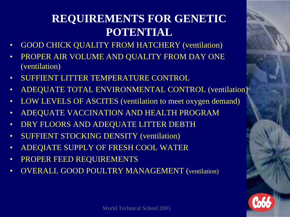
REQUIREMENTS FOR GENETIC POTENTIAL
• GOOD CHICK QUALITY FROM HATCHERY (ventilation)• PROPER AIR VOLUME AND QUALITY FROM DAY ONE
(ventilation)• SUFFIENT LITTER TEMPERATURE CONTROL• ADEQUATE TOTAL ENVIRONMENTAL CONTROL (ventilation)• LOW LEVELS OF ASCITES (ventilation to meet oxygen demand)• ADEQUATE VACCINATION AND HEALTH PROGRAM• DRY FLOORS AND ADEQUATE LITTER DEBTH• SUFFIENT STOCKING DENSITY (ventilation)• ADEQIATE SUPPLY OF FRESH COOL WATER• PROPER FEED REQUIREMENTS• OVERALL GOOD POULTRY MANAGEMENT (ventilation)

World Technical School 2005
Critical Periods In High Yielding Birds Life
• 12 days of incubation to hatch in hatchery.• 1 to 10 days in brood house.• Transport ride from hatchery to brood house.• 11 to 28 days in production house.• Prevention of heat prostration from 16 to 21 weeks of age during
rearing of replacement breeders.• 7 day weight gain.• 28 day weight gain.• ** The performance is determined for the most part the first 28
days for meat or egg production.• Uniformity and sexual maturity before light stimulation for breeders.

World Technical School 2005
TO FIGURE CUBIC VOLUME OF AIR IN ANY HOUSE
• FIRST TAKE THE SIDEWALL HEIGHT AND THE PEAK HEIGHT. ADD THEM TOGETHER THEN DIVIDE BY TWO TO GET AVERAGE HEIGHT
• SECOND MULTIPLY THE LENGTH X WIDTH X HEIGHT AND YOU WILL HAVE THE ACTUAL CUBIC VOLUME OF AIR IN THE HOUSE
• THE CROSS SECTION OF THE HOUSE WILL BE THE WIDTH • X HEIGHT
• EXAMPLE• Length 400 Feet Width 40 Feet Sidewall 8 Feet Peak 12 Feet • 8 + 12 = 20 divided by 2 = 10 feet average high• 400 X 40 X 10 = 160,000 cubic feet of air• The cross section will be 400 square feet

World Technical School 2005
Understanding Relative Humidity
• I. Definition of Relative Humidity is the moisture (water vapor) holding capacity of the air, relative to the dry bulb temperature.
• II. Anytime the temperature in the house and the relative humidity gets too close together and the dew point is reached condensation will form. Floors will get wet and moisture will form on all the equipment in the house.
• III. When a given amount of air is heated it expands, and its capacity to hold moisture is increased. Thus, when air temperatures increase, relative humidity decrease. The opposite occurs when air temperatures are reduced.

World Technical School 2005
Relative Humidity ContinuedThe warmer the air becomes the more moisture (water vapor) itcan contain before it becomes saturated. When the air holds as much moisture as possible at a giventemperature and pressure, the air is saturated or is at dew point. At saturation the dry bulb temperature and dew point are thesame. At ground level an increase in temperature of 20°F (10°C) doublesthe moisture holding capacity of the air.Relative humidity effects both health and comfort of the birds.Too low humidity is also bad for bird health as well.
On the following slide if you were to lay a ruler across 70°F (21°C), line B,and 75% relative humidity, line C, and find the intersecting point online A. Hold the point line A and move the other end of the ruler upto 100°F (37.7°C) you can see the relative humidity would be be reducedto 30% on line C.

World Technical School 2005
Ability of Air to Hold Water VaporPercentRelativeHumidity
Temperature 20
°C °F
30
45 40 110
40100 50
35 90
Ǿ• 25 6070
15 70 50 80
10 90 40
100A B C
RELATIVE HUMIDITY CHANGESWITH TEMPERATURE

World Technical School 2005
Temperature and Humidity Daily OccurrenceThis graft covers from midnight to midnight on a daily basis in most areas of the world.Twice each day in most seasons and most countries the dew point (DP) is reached.
Late AfternoonMid Morning
DPDP
AB
Line A (red) is temperature and there is a gradual increase to a point then it begins togo back down. Line B (blue) is relative humidity increases to dew point early morning and again in thelate afternoon.From mid morning back to midnight the dry bulb temperature is not high enough tocreate a problem. From mid morning until late afternoon there is enough spreadbetween dry bulb and humidity not to create a problem. Once the temperature beginsto go down and the humidity begins to increase is normally when the problem occursand mortality goes up.
World Technical School 2005
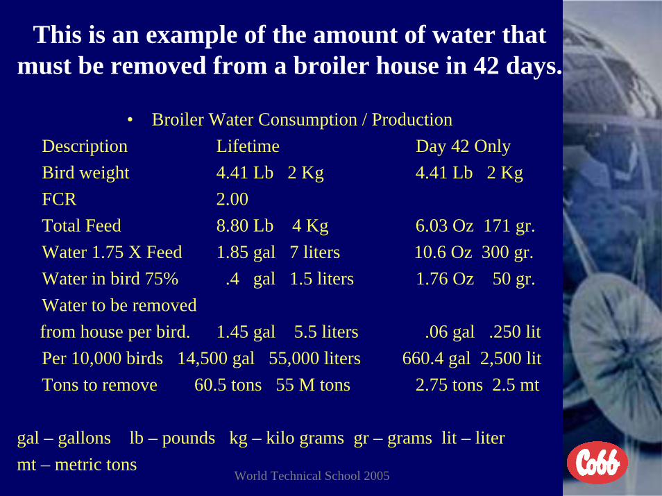
This is an example of the amount of water that must be removed from a broiler house in 42 days.
• Broiler Water Consumption / ProductionDescription Lifetime Day 42 OnlyBird weight 4.41 Lb 2 Kg 4.41 Lb 2 KgFCR 2.00Total Feed 8.80 Lb 4 Kg 6.03 Oz 171 gr.Water 1.75 X Feed 1.85 gal 7 liters 10.6 Oz 300 gr.Water in bird 75% .4 gal 1.5 liters 1.76 Oz 50 gr.Water to be removed from house per bird. 1.45 gal 5.5 liters .06 gal .250 litPer 10,000 birds 14,500 gal 55,000 liters 660.4 gal 2,500 litTons to remove 60.5 tons 55 M tons 2.75 tons 2.5 mt
gal – gallons lb – pounds kg – kilo grams gr – grams lit – litermt – metric tons

World Technical School 2005
Variable Speed Fans VS Fixed Volume Fans
• 1. The only time we ever recommend the use of variable speed fans in chicken houses is when the cubic volume of the house is too large for one fixed volume small fan or too small for one fixed volumelarger fan.
• 2. Because of the efficiency ratings of the newer fans we never use fans smaller than 36 inches or larger than 52 inches any longer.
• 3. In the small houses we can use one 36 inch fan for both minimum and maximum volumes much more effective than we can use two smaller fixed volume fans.

World Technical School 2005
Fan Curve For Variable Speed Fans Compared To Solid State Control
1. The speed of a variable speed fan is determined totally by the voltage supplied to the fan by the control being used. The fan is always more efficient at 100% of speed.
2. The set speed of the fan stated in percentage is only a guide tofollow. It does not signal the actual speed of the fan or the actual volume of the fan being used. The Multifan smart fan will provide this but the cost is much higher than a conventional variable speed fan.
3. The speed of any variable speed fan will vary based on the compatibility of the control to the fan being used.
4. With most variable speed fans 80% of the volume is normally obtained in the last 20% of the fan speed because of the relationship between the pitch of the blade and the speed the prop turns.

World Technical School 2005
Understanding Solid State Ventilation Controls.• 1. House temperature.• Reads actual house temperature.• 2. House Set Point• Desired house temperature.• 3. Minimum set speed.• Minimum set speed of any variable speed fan.• 4. Band width.• Temperature rise to increase fan speed from • minimum set speed to maximum speed.• 5. Temperature offset.• Degrees above of below set point that heaters or cooling • systems come on or off unless they are adjustable. If they • adjustable they come on at set point and go off at a 2 • degree offset.• 6. Humidity shut off point.
– This is the highest level you ever want the relative humidity to be for summer ventilation and the pumps will be shut off.

World Technical School 2005
Requirements Of Solid State Controls
1. Should be as user friendly as possible. The menu should be a one face plate layout without menus and submenus to have to page through to make changes or monitor conditions.
2. Should have the capability to manage the entire environment based on inside temperature, house pressure (inlet air speed), air quality (adjustable cycle timer), and air exchange.
3. Should have the capability to operate the inlets based on staticpressure and not % of fan capacity or % of inlet openings.
4. Should have the capability to monitor the relative humidity and operate the pumps on the cooling system based on a combination of both temperature and relative humidity.
5. Should have the capability to operate a variable speed fan with a settable band width.
6. Should have the capability to automatically switch from minimum ventilation to transition and/or tunnel ventilation when required.

World Technical School 2005

World Technical School 2005

World Technical School 2005

World Technical School 2005

World Technical School 2005

World Technical School 2005
Ventilation Control
• What is the best controller on the market?
–“The Grower”

World Technical School 2005

World Technical School 2005
Environmental Chambers
osu
World Technical School 2005
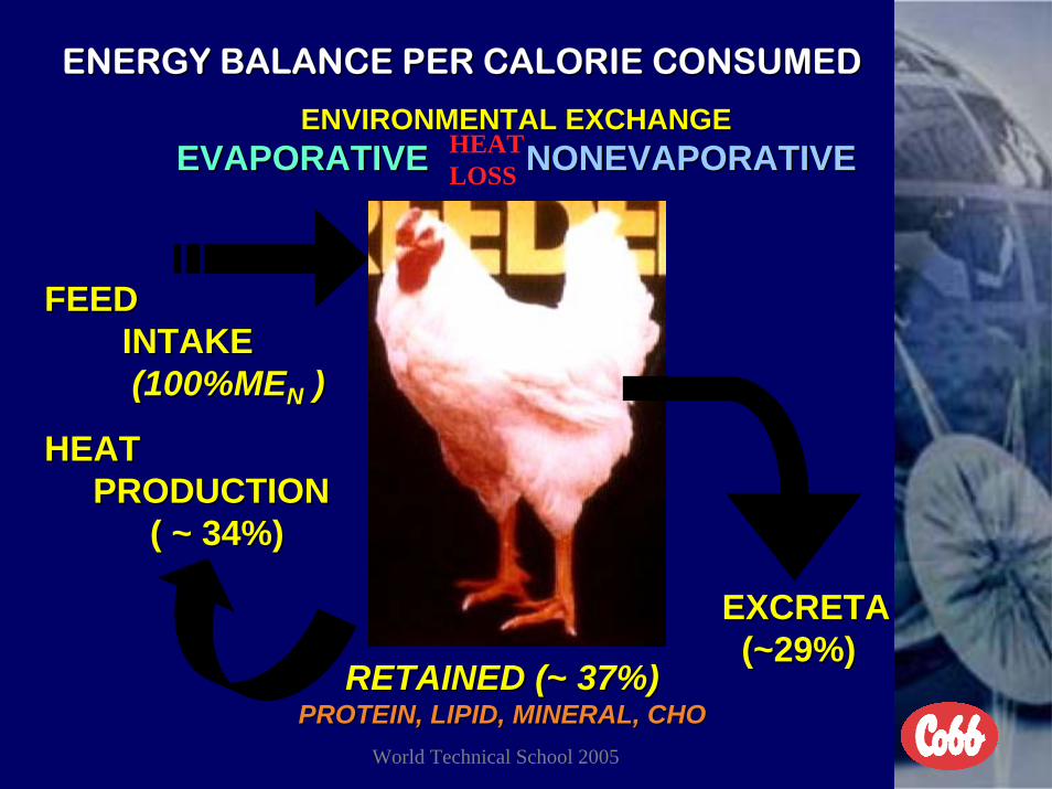
ENERGY BALANCE PER CALORIE CONSUMEDENERGY BALANCE PER CALORIE CONSUMED
ENVIRONMENTAL EXCHANGEENVIRONMENTAL EXCHANGEEVAPORATIVEEVAPORATIVE NONEVAPORATIVENONEVAPORATIVE
FEEDFEEDINTAKEINTAKE(100%ME(100%MENN ) )
HEAT HEAT PRODUCTIONPRODUCTION
( ~ 34%)( ~ 34%)
RETAINED (RETAINED (~~ 37%)37%)PROTEIN, LIPID, MINERAL, CHOPROTEIN, LIPID, MINERAL, CHO
EXCRETAEXCRETA(~29%)(~29%)
HEATLOSS

World Technical School 2005
Definition of Good Air Quality
•Oxygen >19.6%•Carbon dioxide < 0.3%/3000 ppm•Carbon monoxide <10 ppm•Ammonia <10 ppm•Inspirable Dust <3.4mg/m3•*Minimum ventilation must be increased if these parameters are not being met. •Relative humidity >< 45 –65 %•Air speed across birds after 28 days >< 350- 500 FPM
•**Air velocities over 500 FPM is not economically feasible and results are unproven for performance advantages.

World Technical School 2005
Why Use Total House Volume And Not Metabolic Demand To Ventilate Chicken Houses
• Oxygen, carbon dioxide, carbon monoxide, and ammonia are all measured in % or ppm by volume in the air. When these parametersare higher than desired it affects the total volume of air inside the house. To correct the problem the air exchange must be based on the total volume of air affected. We cannot have micro climates inside the house just where the chickens are grown.
• If we grew chickens in a small box then we could use the metabolic demand and still meet the volume requirements of the entire space. The larger the house volume is, the more important it becomes toincrease the air volume needed in the entire house to control the air quality to meet the birds demand.
• Metabolic demands are accurate, but we must get the necessary volume of air to the bird on the floor to meet that demand. This air comes from the total volume of air in the house, requiring us tomanage all the air with air exchange.

World Technical School 2005
EFFECTS OF AIR QUALITY WHEN MINIMUM VENTILATION FANS GO OFF
This is the effect of air quality once minimum ventilation fans go off.Oxygen levels should be >19.6 % at all times. The minimum run timeon the cycle timer to accomplish this is >20% of the time, with thetotal cycle not to exceed 10 minutes.
• During this test oxygen was not measured on a routine basis.• AIR QUALITY
• Fan on 5 minutes 10 minutes 15 minutes• Ammonia 15 PPM 35 PPM 50 PPM 80 PPM• Carbon Dioxide 800 PPM 1500 PPM 2600 PPM 3500 PPM• Humidity 68 % 78 % 86 % 97 %• Temperature 68°-20° 75°-24° 82°-28° 88°-31°
The longer the fans are allowed not to run the worse the air quality and the more the chickens respiratory and immune system will be impaired from optimum development.
World Technical School 2005
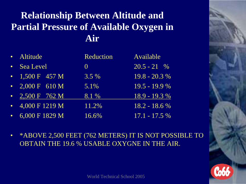
Relationship Between Altitude and Partial Pressure of Available Oxygen in
Air
• Altitude Reduction Available• Sea Level 0 20.5 - 21 %• 1,500 F 457 M 3.5 % 19.8 - 20.3 %• 2,000 F 610 M 5.1% 19.5 - 19.9 %• 2,500 F 762 M 8.1 % 18.9 - 19.3 %• 4,000 F 1219 M 11.2% 18.2 - 18.6 %• 6,000 F 1829 M 16.6% 17.1 - 17.5 %
• *ABOVE 2,500 FEET (762 METERS) IT IS NOT POSSIBLE TO OBTAIN THE 19.6 % USABLE OXYGNE IN THE AIR.

World Technical School 2005
Temperature effects on oxygen demand
• The oxygen demand is at its lowest anytime the house environmentallows the chickens to be in their thermal neutral zone. Ideal effective temperature.
• When the temperature goes down the oxygen demand goes up because the energy of the feed is going to heat production and the birds metabolic demand is greater. This is why we can never sacrifice air volume to accomplish temperature control.
• When the temperature goes up to the point that the birds must pant to try and dispel energy from the body, the oxygen demand goes up.

World Technical School 2005
Chickens Thermal Neutral Zone st ated e a eut a o e
55
60
65
70
75
8085
90
95
0.13
0.25
0.43
0.65
0.92
1.23
1.59
1.99
2.43
2.89
3.36
3.84
4.33
4.83
5.34
5.86
6.39
6.91
7.44
Weight (pounds)
Tem
pera
ture
(oF) 35
32
29.4
26.6
23.8
21.118.3
15.512.7
7 14 21 28 35 42 49 56DAYS
C°

World Technical School 2005
ASCITESONE OF THE HIGHIEST COST TO OUR
INDUSTRY TODAY WORLDWIDE• COLD (FLOOR) BROODING TEMPERATURES• HIGH ALTITUDE HATCHERIES LOW PARTIAL PRESSURE OF
OXYGEN IN THE AIR• INADEQUATE VENTILATION IN HATCHERY LOW OXYGEN
LEVELS BECAUSE OF LOW AIR VOLUME OR PRESSURE• INADEQUATE VENTILATION IN BROOD HOUSE FIRST 10
DAYS AIR VOLUME, AIR DISTIBUTION, AND DRAFTY HOUSES
• DRAFTY HOUSES WITH COOL AIR DRAFTS ON FLOOR• INADEQUATE VENTILATION IN CHICK DELIVERY TRUCK
AIR VOLUME, CONTROL OF RELATIVE HUMISITY AND TEMPERATURE
• RAPID GROWTH RATE GENETICS OF HIGH YEILDING BIRDS
• HIGH ENERGY FEED RATIONS• HIGH LIGHT INTENSITY AND EXTENDED HOURS

World Technical School 2005
RECOMMENDED TEMPERATURES
• BROODING TO SLAUGHTER (DEATH) FOR COBB 500
• 1 DAY TO 7 DAYS 85 - 90°F (29.4 - 32.2°C) Still Air• Directly Under The Brooder 105°F (40.5° C) Still Air• 7 DAYS TO 14 DAYS 85°F (29.4° C) Still Air• 15 DAYS TO 21 DAYS 80°F (26.7° C) Effective Temperature• 22 DAYS TO 28 DAYS 75°F (23.9°C) Effective Temperature• 29 DAYS TO 35 DAYS 70°F (21.1°C) Effective Temperature• 36 DAYS TO DEATH 65°F (18.3°C) Effective Temperature
• Still Air Temperature Is With No Air Velocity Across The Birds To Create A Wind Chill Effect
• You Should Always Consider Effective Temperature After 14 Days• Effective Temperature Includes Temperature, Relative Humidity, and Wind Chill

World Technical School 2005
Thermo Neutral Zone
PEOPLE GET THE IDEA THAT WHEN THE CLIMATE IS HOT THEY DON’T NEED MINIMUM VENTILATION
WRONG!• Birds too cold - eats more feed
- more heat- energy needed from feed- more oxygen needed- higher FCR
• Birds too warm- birds pant- energy needed from feed- more oxygen needed- higher FCR

World Technical School 2005
100°/105°F38°/40.5°C
90°F/32.2°C
Supplemental Water

World Technical School 2005
How to Obtain An Acceptable Body Weight at 7 days of Age
• Air Quality and Ventilation• Feed Management• Temperature Management• Relative Humidity Management• Water Management

World Technical School 2005
Effects Of Brooding Temperatures Effects Of Brooding Temperatures & Proper Ventilation& Proper Ventilation
On Cobb Broiler Performance to 42 DaysOn Cobb Broiler Performance to 42 Days
Brood temp Wt. (g) FCRMortality
(%)
84.9-89.9F29.4-32.2C
2267(5 lbs)
1.71 2.08
75.0-80.0F23.9-26.7C
2219(4.89)
1.77 4.17
70.0-75.0F21.1-23.9C
2149(4.74)
1.82 7.08

World Technical School 2005
EXAMPLE OF COBB 500 BROILER PERFORMANCE
AS HATCHED
AGE GRAMS POUNDS ADG FCR
7 168 .37 24.00 .9014 452 1.00 32.29 1.1121 838 1.85 39.90 1.3228 1,319 2.91 47.11 1.5935 1,659 3.65 47.40 1.6942 2,370 5.22 56.43 1.8549 2,860 6.30 58.36 1.9956 3,253 7.16 58.09 2.05

World Technical School 2005
We Must Restrict The Use Of Tunnel Ventilation Before 28 Days Of Age.
The birds are never fully feathered until 28 days of age.
1. The first 14 days the air speed across the birds should be as low as possible < 40 fpm/.20 mps. Should consider still air temperature.
2. From 15 days of age to 21 days of age the air speed should be limited to no more than 100 fpm/.51 mps. Use of transition ventilation system. Should consider effective temperature.
3. From 22 days of age to 28 days of age the air speed should be limited to no more than 200 fpm/1.02 mps. Use of transition ventilation system. Should consider effective temperature.
4. After 29 days of age the air speed does not have to be restricted and it is now acceptable to use evaporative cooling. Should consider effective temperature and relative humidity.
5. You should always consider effective temperature (after 14 days of age) and not the actual temperature for the best performance of the birds. You can never ventilate chicken houses for people.

World Technical School 2005
Air Speed Across The Birds Compared To Fan Volume And The Cross Section Of The House
House Size 450 feet long X 40 feet wide X 9.5 feet average high = 171,000cubic feet of air to be handled by ventilation system. 36 inch fan 10,500 cfms & 50-52 inch fan 24,500 cfms @ .10 pressure dropAE Air exchange in minutes: (Examples Only)Fan Capacity Cross Section Air Speed
Across Transition Tunnel AE21,000 cfms (2) 4,275 sq. ft. 4.9 fpm 8.131,500 cfms (3) 4,275 sq. ft. 7.4 fpm 5.424,500 cfms (1) 380 sq. ft. (5.7)fpm 16.12 fpm 64.5 fpm 7.049,500 cfms (2) 380 sq. ft. (11.6)fpm 32.57 fpm 130.3 fpm 3.573,500 cfms (3) 380 sq. ft. 48.36 fpm 193.4 fpm 2.398,000 cfms (4) 380 sq. ft. 64.47 fpm 257.9 fpm 1.7
122,500 cfms (5) 380 sq. ft. 322.4 fpm 1.4147,000 cfms (6) 380 sq. ft. 386.8 fpm 1.2171,500 cfms (7) 380 sq. ft. 451.3 fpm 1.0196,000 cfms (8) 380 sq. ft. (45.8)fpm 515.8 fpm .872 36-inch fans or 1 50/52-inch fan to run on cycle timer and temperature override196,000 cfms divided by 400 = 490 square feet of 6 inch pads needed

World Technical School 2005
Metric Air Speed Across Birds Compared To Fan Volume And The Cross Section Of The House
House Size 450 feet long X 40 feet wide X 9.5 feet average high = 171,000cubic feet of air to be handled by ventilation system. 36 inch fan 10,500 cfms & 50-52 inch fan 24,500 cfms @ .10 pressure dropAE Air exchange in minutes: (Examples Only)Fan Capacity Cross Section Air Speed
Across Transition Tunnel AE21,000 cfms (2) 4,275 sq. ft. 025 mps 8.131,500 cfms (3) 4,275 sq. ft. .037 mps 5.424,500 cfms (1) 380 sq. ft. (.029)mps .082 mps .328 mps 7.049,500 cfms (2) 380 sq. ft. (.059)mps .165 mps .662 mps 3.573,500 cfms (3) 380 sq. ft. .246 mps .982 mps 2.398,000 cfms (4) 380 sq. ft. .327 mps 1.31 mps 1.7
122,500 cfms (5) 380 sq. ft. 1.64 mps 1.4147,000 cfms (6) 380 sq. ft. 1.96 mps 1.2171,500 cfms (7) 380 sq. ft. 2.29 mps 1.0196,000 cfms (8) 380 sq. ft. (.233)mps 2.62 mps .872 36-inch fans or 1 50/52-inch fan to run on cycle timer and temperature override196,000 cfms divided by 400 = 490 square feet of 6 inch pads needed

World Technical School 2005
Air Speed Too Fast For Young Chicks8 Days Old Air Speed 450 fpm/2.3 mps

World Technical School 2005
Functions Of Any Ventilation System
1. Create an air exchange in the house based on cubic volume.2. Provide Oxygen (air volume) to meet the demand for the birds.3. Allow for control of relative humidity.4. Insure good air quality at all times.5. Keep floors dry.6. Remove negative gasses from the environment.7. Obtain necessary pressure drop across inlets in the house.8. Accomplish an acceptable effective temperature.9. Manage the environment for best results.10. Improve overall production efficiencies.

World Technical School 2005
Ammonia Levels
• Always evaluate at bird level.• Ammonia Levels:
– Target <10 ppm– Humans Detect 5 ppm– Eye Damage 102 ppm (in as little as 12 hrs)
• starve outs/ dehydration– Wt Loss/ FC 25-51 ppm – Cilia stop moving 20 ppm (3 minutes)
• respiratory tract damage• vaccine reactions• airsac

World Technical School 2005
Effect of Ammonia
• Increased Ascites• Foot pad burns• Eye burns• Breast blisters/Skin irritations• Decreased weights• Poor uniformity• Disease susceptibility• Employee Discomfort

World Technical School 2005
Early House Design Open Top ChimneyNo Air Velocity Across Birds On Floor
CHIMNEY
HEATFRESH AIR
FRESH AIR &
OXYGEN
NOTHING AT BIRD LEVEL
World Technical School 2005
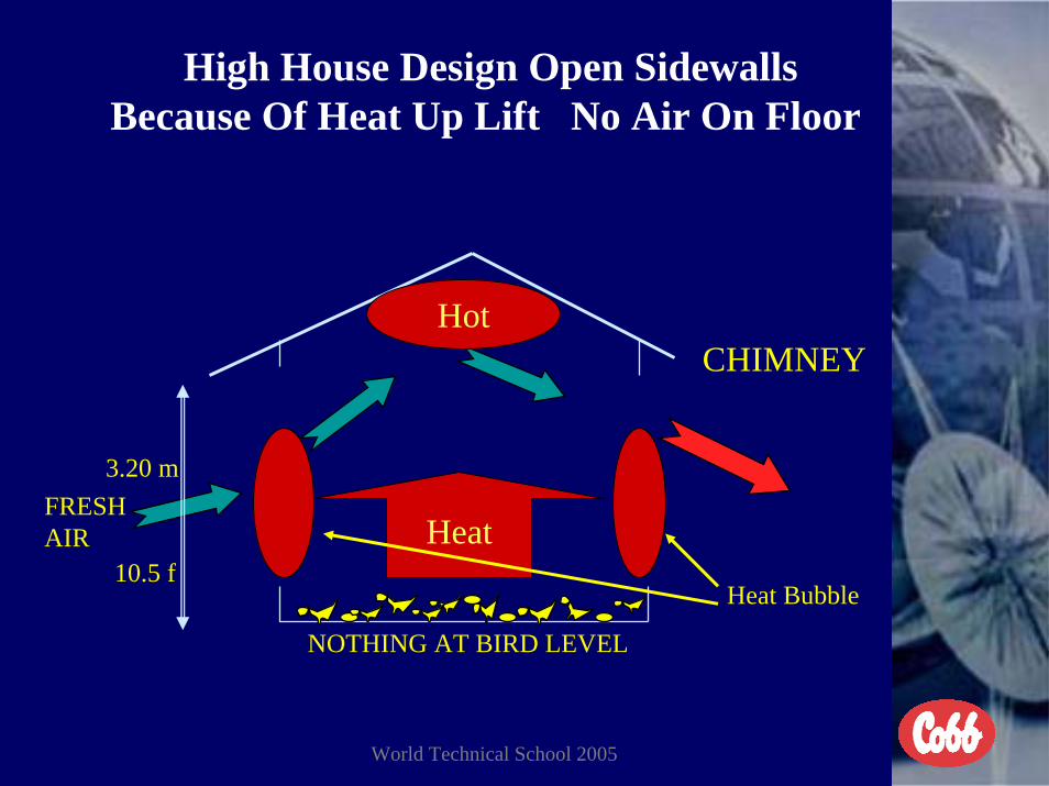
High House Design Open SidewallsBecause Of Heat Up Lift No Air On Floor
CHIMNEY
3.20 m
10.5 fHeat
Hot
FRESHAIR
NOTHING AT BIRD LEVEL
Heat Bubble

World Technical School 2005
Improved House Design Drop Sidewalls At Top Of Opening Fair Air Velocity Across Birds At
Floor Level
2.40 m
Heat as InsulatorPositive Negative
1.5 m5.0 F 7.9 F
FAIRLY GOOD AT BIRD LEVEL

World Technical School 2005
Four Sources Of Heat In A Chicken House.I. Radiant heat on the house created by the sun. II. BTU’s Generated From The Energy Of The Birds
1 day old - 1 BTU28 days-16 weeks old 6 BTU’s per pound of body weight16 weeks-65 weeks old 8 BTU’s per pound of body weight
III. Radiant BroodersShould be used for brooding only to obtain desired floor(litter) temperature during early age. A radiant brooder willonly increase the house temperature by convection. They are specifically designed to heat a solid surface byradiation. When radiant heaters are used to obtain house temperatureor to try and dry litter the relative humidity will actuallyincrease. This will only partially work if the minimumventilation fans were running all the time.
IV. Space Heaters (Supplemental Heat)Should be used at all times to accomplish desired house (air)temperature. Can also be used to control relative humidity.

World Technical School 2005
All Four Seasons There Are Four Sources Of Heat In Chicken Houses
CHICKENS, RADIATION FROM SUN, SPACE HEATERS, AND RADIANT BROODERS
Heat
SUN
SPACEHEATER
BROODER
CHICKENS
SUMMER FALLSPRINGWINTER

World Technical School 2005
Poultry House Ventilation Systems
1. NATURAL VENTILAITON There is no air exchange in the house unless the wind is blowing and the curtains are properly adjusted. To be used only when total mechanical ventilation is not available, however it should include minimumventilation fans and inlets for early age.
2. MINIMUM VENTILATION SYSTEM This system should be across the house for best results. To be used for cool weather and during brooding. Low air velocity (< 40 fpm/.20 mps) over the birds and long air exchange rate. This system is for air quality and a slight amount of temperature control. Sidewall inlets must direct the incoming into the peak of the house.(Highest return on investment of any of the systems.)
3. TRANSITION VENTILATION SYSTEM To be used to allow for a much better air exchange rate inside the house, without high air velocity across the birds, until the birds are more than 28 days of age. Sidewall inlets must direct the incoming air into the peak of the house.
4. SUMMER VENTILATION SYSTEM To be used for temperature control and create a high air speed (velocity) across the birds based on bird age and temperature. To lower the effective temperature and reduce heat prostration. Proper inlet pressure should still be used.

World Technical School 2005
Order of Best Ventilation Efficiencies of Chicken Houses
1-2Tunnel ventilation with foggers and minimum ventilation.
2-1 Tunnel ventilation with evaporative cooling and minimum ventilation.
Open wall house with positive pressure fans in sidewall at 60 degree angle.
All houses have minimum ventilation going across the house.
3
Open wall house with stir fans down the center of the house in one row.4

World Technical School 2005
Ventilation efficiencies continue.
Stir fans staggered down center of the house in two rows.5
Open wall house.
6 Open wall house and hope the wind blows.
3
4In hotclimates
In mildclimates Closed cross ventilated houses with foggers.

World Technical School 2005
Natural Ventilation System
• This system should always include sidewall fans and inlets for minimum ventilation at least for the first 14 days.
• This system should only be used when the outside environment is ideal and/or there is no mechanical ventilation system available.
• When this system is used the sidewall curtains should be properly managed to prevent the prevailing wind from seeking the path of least resistance.
• This system will only be successful for good performance when the climate dictates no need for good temperature control, relative humidity control, or wind chill effect.

World Technical School 2005
Minimum Ventilation Fan With Natural Ventilated HouseCurtain Open
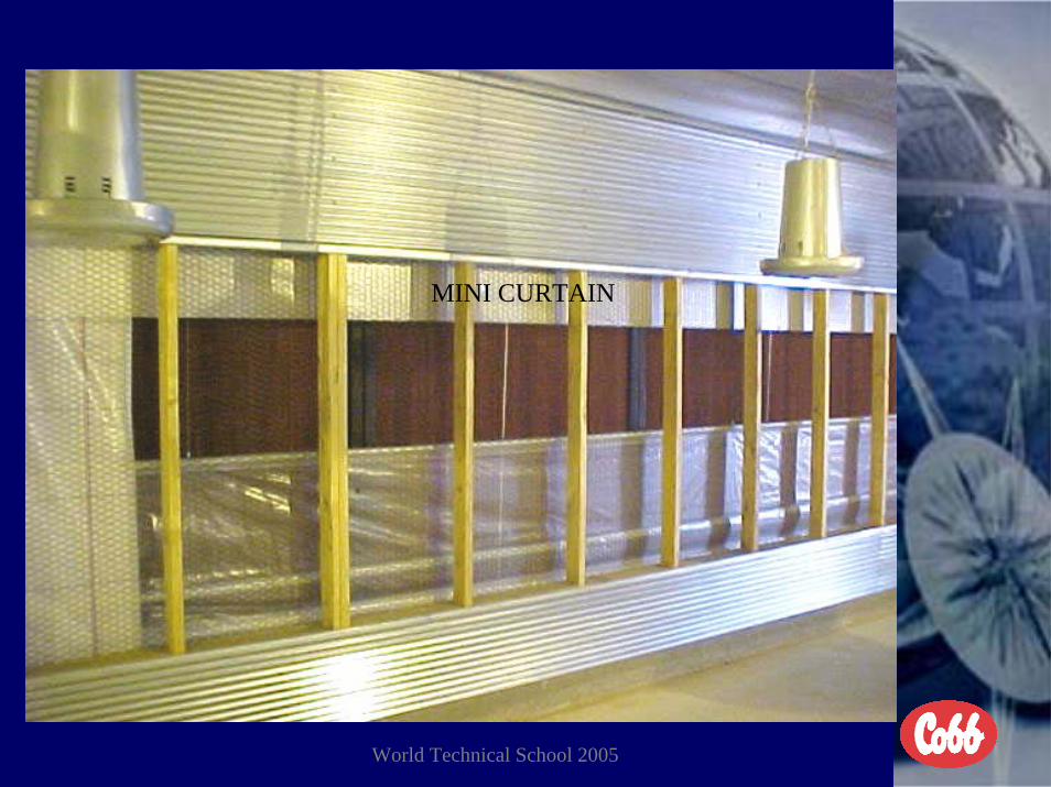
Mini Curtain

World Technical School 2005
Minimum Ventilation Fan With House Closed

World Technical School 2005
How To Manage Sidewall Curtains In Naturally Ventilated Chicken Houses For Better
Performance
• To improve air exchange in the house and speed the air velocity up entering the house you need to adjust the windward curtain higher than on the off side of the house. The inlet ratio should be 1 to 4 opening area.
• To lower the air exchange in the house and slow the air velocity down entering the house you need to adjust the windward curtain lower than on the off side of the house. The inlet ratio should be 1 to 4 opening area.
• To obtain the same air speed entering the house as the prevailing wind each curtain should be adjusted the same. If the sidewall opening is too high the fresh air will get into the thermal up draft and prevent the air from moving across the birds on the floor. This is done when you want to obtain as much wind chill on the birds as possible when the opening is not too high from the ground.
• The reason these factors are obtained is the fact that wind blows with gravity or terrain level.

World Technical School 2005
Improved House Design With Drop Curtain Sidewalls At Top Of Opening For Natural
Ventilation
Heat as Insulator NegativePositive
To increase air exchange in the housewithout high air velocity across birds.
Higher curtain onwindward side ofthe house.

World Technical School 2005
Improved House Design With Drop Curtain Sidewalls At Top Of Opening For Natural
Ventilation
Heat as Insulator NeutralPositive
To decrease air exchange in the housewithout high air velocity across birds.
Lower curtain on windward side ofthe house.

World Technical School 2005
Improved House Design With Drop Curtain Sidewalls At Top Of Opening For Natural
Ventilation
Heat as InsulatorPositive
Curtains even on bothsides of the house.
To increase air exchange in the houseand higher air velocity across birds.

World Technical School 2005
MINIMUM VENTILATION PRIORITIES
1. STOP AIR LEAKS (HOUSE AIR TIGHT AS POSSIBLE )2. AIR EXCHANGE RATE BASED ON CUBIC VOLUME OF THE
HOUSE (AIR VOLUME)3. PRESSURE DROP ACROSS THE INLETS
(AIR SPEED ENTERING HOUSE)4. DIRECTION OF AIR ACROSS INLETS ENTERING THE HOUSE
(INTO PEAK OF HOUSE)5. SETTINGS ON CYCLE TIMER(MINIMUM RUN TIME TO MEET
OXYGEN DEMAND OF >19.6%)6. CONTROL OF RELATIVE HUMIDITY (45 TO 65 %)7. TYPE OF HEATING (SPACE AND RADIANT)8. TEMPERATURE CONTROL (BASED ON AGE OF BIRDS)9. SEQUENCE OF CONTROL OPERATION
(SETTINGS OF CONTROLS)

World Technical School 2005
Factors For Minimum Ventilation To Work Properly And Keep Floors Dry
• I The house must be air tight enough to achieve the necessary negative pressure with the minimum number of fans.
• II. Fans must have the capability to work against the necessarynegative pressure and achieve the required air exchange rate.
• III. Inlets must have the capability to react to the fan volume and control the house pressure (pressure drop across the inlets) consistently based on the width of the house being ventilated. (Properly weighted or suspension kept adjusted.)
• IV. Inlets must direct the air into the peak of the house to prevent drafts on the floor and utilize the energy accumulated up in the peak.
• V. Temperature must be adequate to allow for expansion of the outside air (> 55°F/13°C) to increase the moisture holding capacity of the air and reduce the relative humidity.
• VI. The cycle timer must be adjustable and run time increased as air quality begins to deteriorate or birds get older.

World Technical School 2005
Factors For Minimum Ventilation To Work Properly Continues
• VII. There must be a temperature override to either speed up a variable speed fan or override the cycle timer on fixed volume fans.
• VIII.The shutters on the summer fans must be air tight or all but two covered during severe cold weather.
• IX. When the house is more than 250 feet/76 meters long the minimum ventilation should be across the house. If mechanical operated (baffle) inlets are used, when sidewall fans are being used only the inlets on the opposite side of the house should be used.
• X. Minimum ventilation fans should always be used on the windy side of the house (North or East) in cold weather to allow for propercontrol of the house pressure. (No minimum inlet have the capability to work against wind speed on the outside of the house without excellent wind protection.)

World Technical School 2005
Minimum Ventilation System
• Air exchange must equal fan volume that ranges from 1 air exchange every 8 minutes to one air exchange every 5 minutes for total house cubic volume. The air velocity across the birds should be very low.
• First stage (minimum) must be fan volume equal to 1 air exchangeevery 8 minutes and run a minimum of 20 % of the time. This stage should operate on a cycle timer and temperature override. Inlets should direct air into peak of house.
• Second stage (maximum) must be fan volume equal to 1 air exchange every 5 minutes and run 100 % of the time.
• All stages must have the ability to get the necessary pressure drop across the inlets of the house based on width of the house.

World Technical School 2005
Cross-flow for Cold Weather Ventilation
MINIMUM VENTILATION INLETS EVENLY SPACED

World Technical School 2005
Formula For Figuring Minimum Ventilation Inlets Using Air Cannons and VF 48 or TJP2100
Inlets1. First take length of house and divided it by 10 and add 8 for number of
air cannons needed. Air cannons should be installed at the same angle as the pitch of the roof. The air cannons should not be more than 30 inches (76 cm) long. Air cannons are for air distribution and direction and not volume.
Example(450 feet divided 10 (1 every 10 feet opposite fans) + 8 (2 in each corner
of the house) = 53 2.5 inch air cannons needed)2. Second take the total minimum ventilation fan volume at .010 pressure
drop subtract estimated house leaks and air cannon air volume then divide by 2,000 cfms = number of VF 48 inlets needed. VF 48 are for air volume and control of house pressure drop across inlets.
Example3 36-inch fans at 10,200 cfms = 30.600 cfms – 6,000 cfms for leaks –
2,400 cfms for air cannons = 22,200 cfms divided by 2,500 cfms per VF 48 = 9 VF 48’s needed weighted to .055 pressure drop.

World Technical School 2005
MINI CURTAIN
VF 48 INLET AIR CANNON

World Technical School 2005
TJP2100 OR TJP2600
VF48
World Technical School 2005
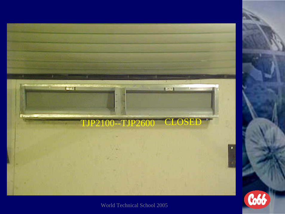
TJP2100--TJP2600 CLOSED

World Technical School 2005
OPEN BY HOUSE PRESSURE

World Technical School 2005
MECHANICALLY OPERATED INLET
World Technical School 2005
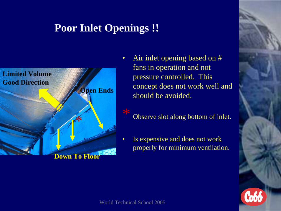
Poor Inlet Openings !!
• Air inlet opening based on # fans in operation and not pressure controlled. This concept does not work well and should be avoided.
* Observe slot along bottom of inlet.
• Is expensive and does not work properly for minimum ventilation.
*
Down To Floor
Limited VolumeGood Direction
Open Ends
World Technical School 2005
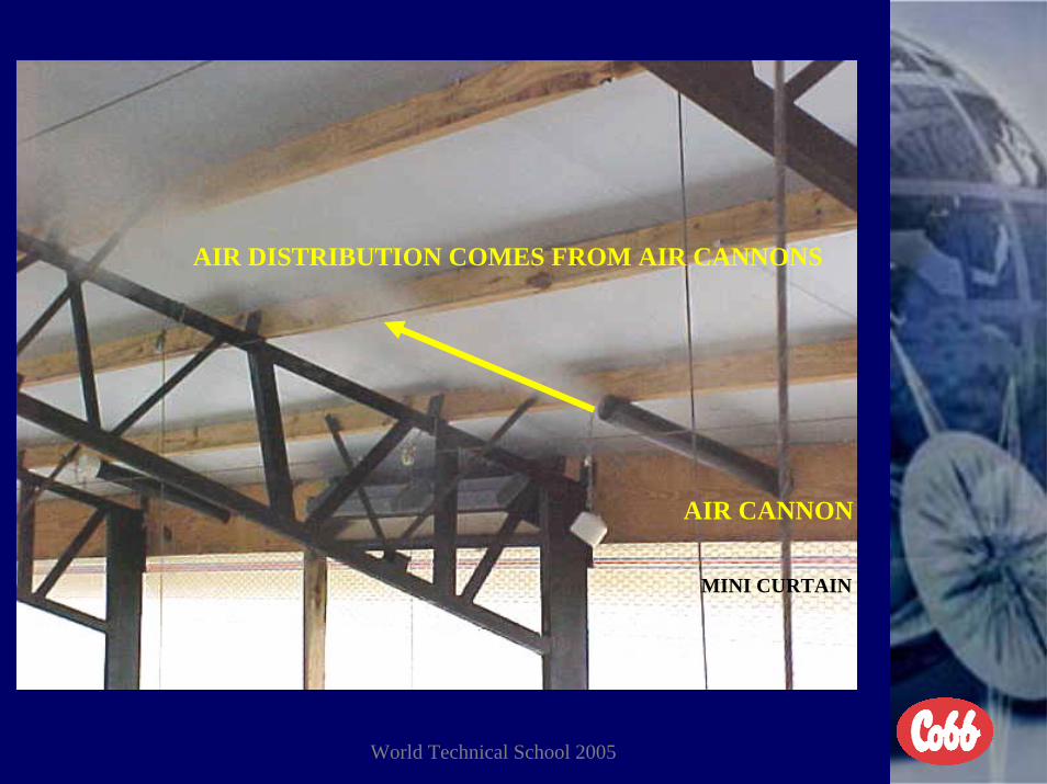
AIR DISTRIBUTION COMES FROM AIR CANNONS
AIR CANNON
MINI CURTAIN

World Technical School 2005
VOLUME COMES FROM VF48, TJP2100, OR MECHANICAL INLETS
VF 48
MINI CURTAIN

World Technical School 2005

World Technical School 2005
CHECK PRESSURE DROP ACROSS INLETS TO SET CONTROLS

World Technical School 2005
CHECK AIR SPEED ENTERING HOUSE TO SET PRESSURE ON CONTROLS

World Technical School 2005
CORRECT PRESSURE DROP ACROSS INLETS
World Technical School 2005
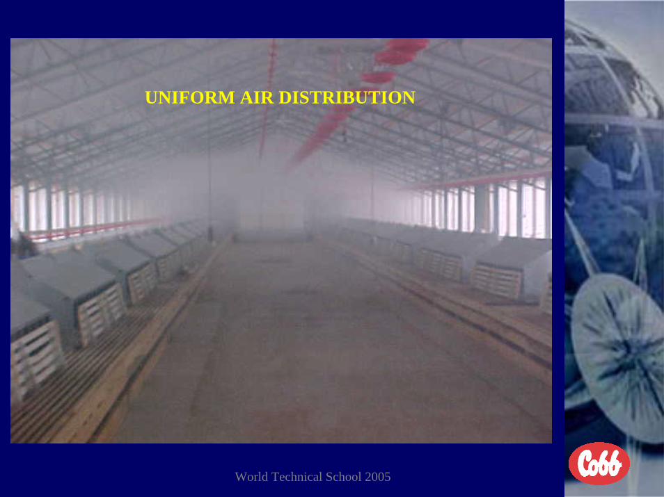
UNIFORM AIR DISTRIBUTION

World Technical School 2005
Understanding Minimum Ventilation InletsI. Air Cannons.
Intended only for air distribution to introduce cold outside air into the peak of the house. Never intended for air volume. Air cannons should never exceed 30 inches long.
II. VF48 inlets.Intended for air volume and to control the pressure drop across the inlets. Must be properly weighted to accomplish proper air speed through air cannons and control house pressure based on house width. Will react completely to fan volume.
III. TJP2155 -2655 inlets.Same as VF48 but comes from factory counter weighted to desired house width.
IV. Mechanically operated sidewall inlets.Must have drive motor, suspension system, additional control module, high maintenance. Must either open before fans begin torun or remain open after fans go off thus loosing far too much energy creating high utility costs.

World Technical School 2005
Pressure Drops (Negative Pressure)
• I Actual Negative Pressure (pressure drop) from inside the house to atmosphere.
• *This is created only by the fan volume compared to the inlet area openings, including unwanted leaks.
• II. Pressure drop across inlets (air speed) entering the house. This is the important one to the chicken business for air distribution.
• *This is created by the negative pressure with the resistance of the inlets taken into consideration. The more the resistance the higher the negative pressure will be above the pressure drop across the inlets.
• In a normal curtain wall chicken house the difference in the actual negative pressure and pressure drop across the inlet is approximately .02 inches of water. The more the house leaks the more difference there will be in the two pressures.

World Technical School 2005
FORMULA FOR FIGURING INLET AREA BASED ON HOUSE
PRESSURE AND/OR WIDTH OF THE HOUSE
• THE HOUSE WIDTH SHOULD DETERMINE THE PRESSURE DROP YOU USE FOR BEST RESULTS AND TO FIGURE INLET SPACE FOR BEST DISTRIBUTION OF AIR THOUGH THE HOUSE
• EXAMPLES OF PRESSURE DROPS USED • PRESSURE -INLET SPACE -WIDTH OF HOUSE--AIR SPEED• .03 1 SQ.IN. 4.0 CFMS 10.4 M 34 F 700 FPM• .04 1 SQ.IN. 4.5 CFMS 10.9 M 36 F 800 FPM• .05 1 SQ.IN. 5.0 CFMS 12.2 M 40 F 900 FPM• .06 1 SQ.IN. 5.5 CFMS 13.7 M 45 F 1000 FPM• .07 1 SQ.IN. 6.0 CFMS 15.2 M 50 F 1100 FPM• .08 1 SQ.IN. 6.5 CFMS 18.3 M 60 F 1200 FPM• ** 144 square inches in one square foot
World Technical School 2005
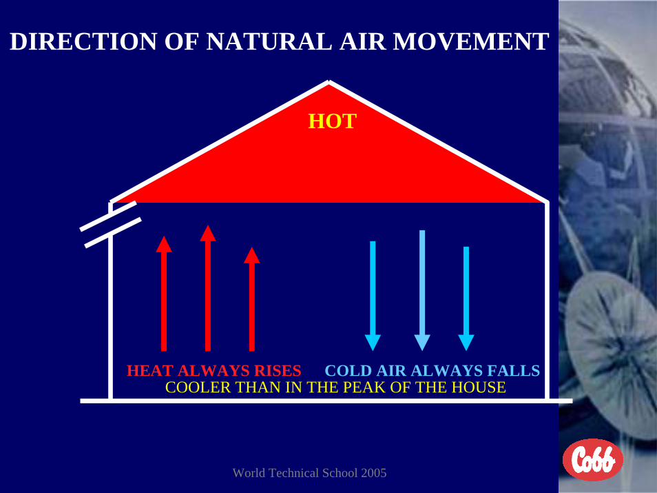
DIRECTION OF NATURAL AIR MOVEMENT
HOT
HEAT ALWAYS RISES COLD AIR ALWAYS FALLSCOOLER THAN IN THE PEAK OF THE HOUSE

World Technical School 2005
Cross-Flow For Minimum Ventilation
HOT
COOL
WARM, DRY, EVEN DISTRIBUTION OF AIR
HEAT

World Technical School 2005
Cross-Flow Ventilation With Continuous Slot For Second Stage Air Volume
HOT
COOLOUTSIDEAIR
COMFORTABLE ANIMALS, WARM DRY FLOORS, EVEN DISTRIBUTION OF AIR, LOW ENERGY COST
TEMPERATURE WILL ALWAYS INCREASE
BADAIR

World Technical School 2005
Cross-Flow Ventilation With Counter Balanced Inlet For Second Stage Air Volume
HOT
COOLOUTSIDEAIR
COMFORTABLE ANIMALS, WARM DRY FLOORS, EVEN DISTRIBUTION OF AIR, AND LOW UTILITY COSTS
TEMPERATURE WILL ALWAYS INCREASE
BADAIR

World Technical School 2005
Wrong Position Directional Flap
Air flow of cold air goingtowards litter and chicks
Air flow directed towardhighest part of roof

World Technical School 2005
Poor Inlet Openings !!
• Air inlet opening based on # fans in operation and not pressure controlled. This concept does not work well and should be avoided.
• * Observe slot along bottom of inlet
• Is expensive and does not work properly for minimum ventilation.
*
Down To Floor
Limited VolumeGood Direction Open Ends

World Technical School 2005
Cross-flow VentilationWith very low pressure drop across inlets
HOT
COOLAIR
COLD WET FLOORS, WINDCHILL STRESS ON CHICKS, NO USE OF EXISTING EN\ERGY, HIGH UTILITY COSTS
FANON
CoolAir

World Technical School 2005
WHEN TOP OF HOUSE & UNDER THE SIDEWALLCURTAINS LEAK
CHIMNEY
HEAT
FRESH AIR &
OXYGEN
HEAT,
WIND CHILLWIND CHILL
EFFECT
MONEY
COLD WET FLOORS, STRESS CHICKS,AMMONIA, HIGH UTILITY COST, ASCITESAND BAD OVERALL PERFORMANCE

World Technical School 2005
Solutions When Inlet Pressure Is Too Low
• Seal as many house leaks as possible permanently.• Make sure belts are tight on belt drive fans.• Make sure all shutters are kept clean.• Make sure all summer fan shutters are in good state of repair and
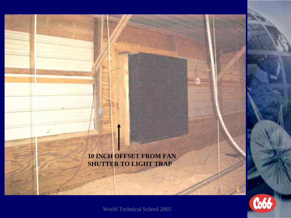
will seal when fan is off.• Increase fan capacity until the proper pressure is obtained.• In blackout houses make sure the light traps are larger enough
for the fan capacity and the distance between the fan and shutter is adequate.
• Make sure fan being used is capable of working against the necessary pressure.
• With VF48 inlets insure the weights are on the air inlet louversand they are correct weight.

World Technical School 2005
Cross-flow VentilationVery high negative pressure across inlets
HOT
COOLAIR
COOL FLOORS, HIGH AMMONIA, HIGH UTILITY COSTS,LACK OR OXYGEN AT FLOOR LEVEL
FANON
HOTAIR
NO FRESH AIR NEVER GETS TO THE FLOOR

World Technical School 2005
Solutions When Inlet Pressure Is Too High
• Increase inlet capacity in the house.• Decrease the fan capacity as long as the minimum
volume is being met.• Decrease inlet pressure setting on solid state control.• Make sure temperature override has not turned on too
much fan capacity for minimum inlets.• Check to see that birds hasn’t built nests in inlets.• See that light traps are not stopped up with dirt.

World Technical School 2005
Improved House Design With Drop Ceiling (Tent) Using Jet Air - Positive Pressure Tube For Minimum
Ventilation
HOT AIR
This will provide and air exchange in the house as well as evenly distribute heat entire across floor.
JETAIRTUBE
2 o’clock10 o’clock
Fan capacity tobe determinedby total cubic volume of air needed for oxygendemand.
Size and number ofholes to be determinedby total fan capacity+ length of tube.

World Technical School 2005
TRANSITION VENTILATION SYSTEM
1. This system must have enough (minimum) sidewall inlets equally placed on both sides of the house from end to end to meet the volume capacity of at least 3 of the tunnel ventilation fans and are controlled by counter weights or negative pressure. *With fans on one end of the house and inlets evenly placed on each side of the house from end to end the air velocity across the birds will be ¼ of what it is with inlets on the opposite end of the house.
2. The inlets must still direct the air into the peak of the house to prevent wind chills on the floor.
3. Once the summer (tunnel) ventilation system begins to operate the (minimum) sidewall inlets should close and the summer inlets begin to open and maintain the proper inlet pressure for good air distribution down through the house.

World Technical School 2005
Transition Ventilation For A Better Air Exchange Without High Air Velocity
EVEN AIR DISTRIBUTION

World Technical School 2005
FORMULA FOR FIGURING INLETS FOR MINIMUM/TRANSITION VENTILATION
1. CHOOSE THE INLETS YOU ARE GOING TO USE FOR THIS APPLICATION
2. DETERMINE THE AIR VOLUME OF EACH INLET BASED ON THE ACTUAL PRESSURE YOU ARE GOING TO BE USING
3. INSTALL ENOUGH INLETS EQUALLY SPACED ON EACH SIDE OF THE HOUSE TO MATCH THE CAPACITY OF THE NUMBER OF FANS TO BE USED AT THE ACTUAL WORKING PRESSURE
4. THE INLETS SHOULD BE STAGGERED FROM SIDE TO SIDE DOWN THROUGH THE HOUSE
5. INSTALL A STATIC PRESSURE INLET CONTROL ON EACH SIDE OF THE HOUSE IF THEY ARE BEING OPERATED MECHANICALLY
6. WHEN IN MINIMUM VENTILATION ACROSS THE HOUSE, ONLY ONE SIDE OF THE INLETS SHOULD BE OPEN OPPOSITE THE FANS.
7. ALL THE SIDEWALL INLETS SHOULD BE CLOSED WHEN IN FULL TUNNEL VENTILATION

World Technical School 2005
TRANSITION INLETS ON BOTHSIDES OF THE HOUSE

World Technical School 2005
When Cycle Timer Is Used With Transition Ventilation
• Make sure fresh air entering the house passes the next inlet as it moved down through the house to insure fresh air is introduced from one end of the house to the other.
• The minimum run time on the timer still must be at least 20% of the time on a 5 or 10 minute timer.
• The inlet pressure is just as important as when going across thehouse for minimum ventilation.
• Inlets must always direct air into the peak of the house.
• Insure wind chill is not too high for chicks when fans are in operation based on age and size.
World Technical School 2005
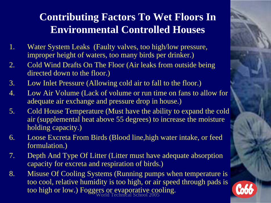
Contributing Factors To Wet Floors In Environmental Controlled Houses
1. Water System Leaks (Faulty valves, too high/low pressure, improper height of waters, too many birds per drinker.)
2. Cold Wind Drafts On The Floor (Air leaks from outside being directed down to the floor.)
3. Low Inlet Pressure (Allowing cold air to fall to the floor.)4. Low Air Volume (Lack of volume or run time on fans to allow for
adequate air exchange and pressure drop in house.)5. Cold House Temperature (Must have the ability to expand the cold
air (supplemental heat above 55 degrees) to increase the moisture holding capacity.)
6. Loose Excreta From Birds (Blood line,high water intake, or feed formulation.)
7. Depth And Type Of Litter (Litter must have adequate absorption capacity for excreta and respiration of birds.)
8. Misuse Of Cooling Systems (Running pumps when temperature is too cool, relative humidity is too high, or air speed through pads is too high or low.) Foggers or evaporative cooling.

World Technical School 2005
Doing the Right Things...Doing the Right Things...FOR MINIMUM VENTILATION
Minimum ventilation mostly for air quality
FAN
AIR CANNONS
SECOND STAGE INLETS
Ventilation Design, Installation, and Management

World Technical School 2005
PRIORITIES FOR SUMMER VENTILATION
1. AIR SPEED ACROSS THE BIRDS (300 TO 500 FPM)2. AIR EXCHANGE IN THE HOUSE (LESS THAN 1.2 MINUTES)3. CONTROL OF RELATIVE HUMIDITY (BETWEEN 45 TO 65%)4. PRESSURE DROP ACROSS INLETS (AIR SPEED ENTERING THE
HOUSE BASED ON WIDTH OF THE HOUSE)5. TEMPERATURE CONTROL (USE EFFECTIVE
TEMPERATURE NOT DRY BULB ALONE)6. RUN ALL FANS BEFORE PUMPS (LAST FANS RUN 78°F/25.5°C)7. RUN PUMPS ONLY WHEN NEEDED (NEVER BEFORE 82°F/27.8°C OR
IF RELATIVE HUMIDITY IS ABOVE 70%)8. YOU CANNOT CONTINUE TO TRY AND DROP DRY BULB
TEMPERATURE AND INCREASE THE RELATIVE HUMIDITY TOO HIGH

World Technical School 2005
We Must Restrict The Use Of Tunnel Ventilation Before 28 Days Of Age.
The birds are never fully feathered until 28 days of age.
1. The first 14 days the air speed across the birds should be as low as possible < 40 fpm/.20 mps. Should consider still air temperature.
2. From 15 days of age to 21 days of age the air speed should be limited to no more than 100 fpm/.51 mps. Use of transition ventilation system. Should consider effective temperature.
3. From 22 days of age to 28 days of age the air speed should be limited to no more than 200 fpm/1.02 mps. Use of transition ventilation system. Should consider effective temperature.
4. After 29 days of age the air speed does not have to be restricted and it is now acceptable to use evaporative cooling. Should consider effective temperature and relative humidity.
5. You should always consider effective temperature (after 14 days of age) and not the actual temperature for the best performance of the birds. You can never ventilate chicken houses for people.

World Technical School 2005
FORMULA TO FIGURE SUMMER FANS FOR TUNNEL VENTILATION
EXAMPLE HOUSE 40 FEET X 400 FEET X 10 FEET = 160,000 CUBIC FEET OF AIR TO BE HANDLED
TAKE CROSS SECTION OF HOUSE X DESIRED AIR SPEED = TOTAL CFMS OF FAN CAPACITY NEEDED THEN DIVIDED TOTAL CFMS NEEDED BY RATING OF FAN TO BE USED AT PROPER PRESSURE DROP
EXAMPLE(400 SQUARE FEET CROSS SECTION X 450 FEET PER MINUTE =
180,000 CFMS DIVIDED BY 21,500 CFMS PER FAN) = 8 FANS WHEN THIS METHOD IS USED YOU MUST NOW CHECK THE
AIR EXCHANGE BY DIVIDING THE CUBIC VOLUME OF THE HOUSE BY THE ACTUAL FAN VOLUME = AE
EXAMPLE(8 FANS X 21,500 CFMS PER FAN = 172,000 TOTAL CFMS160,000 CUBIC FEET DIVIDED BY 172,000 CUBIC FEET = .93 OF A
MINUTE AIR EXCHANGE)

World Technical School 2005
SLANTWALL CONE FANS
World Technical School 2005

World Technical School 2005

World Technical School 2005

World Technical School 2005
SUMMERFANS
ENTER HOUSE
FAN VESTIBULEFAN VESTIBULE

World Technical School 2005

World Technical School 2005

World Technical School 2005

World Technical School 2005

World Technical School 2005

World Technical School 2005

World Technical School 2005

World Technical School 2005

World Technical School 2005
56 INCH X 56 INCHTRAP / 36-INCH FAN

World Technical School 2005

World Technical School 2005
SUMMER FANS LIGHT TRAPS
VESTIBULE

World Technical School 2005
SLANT WALL FANS
FAN VESTIBULE

World Technical School 2005
World Technical School 2005
10 INCH OFFSET FROM FAN SHUTTER TO LIGHT TRAP

World Technical School 2005
Minimum and Summer Fans

World Technical School 2005
INSIDE HOUSEVESTIBULE

World Technical School 2005
C2000 CEILING INLET WITH W500 OPEN

World Technical School 2005
Tunnel for Hot Weather VentilationPROPER PRESSURE
EVEN AIR DISTRIBUTION
PROPER PRESSURE

World Technical School 2005
Tunnel Ventilation With Low Inlet Air Speed
No Air
No Air
No Air
LOW PRESSURE
UNEVEN AIR DISTRIBUTIONHIGH AIR SPEED
HOT
HOT
With low airspeed at air inlet (<500 fpm) dead spots will appear in the house and air velocity in center will be very high
LOW PRESSURE

World Technical School 2005
TUNNEL VENTILATION WITH INLETS ON END OF HOUSE
AIRFLOW GOESBACKWARDS
POOR AIR DISTRIBUTION
Based on air speed entering house , at some point the airwill drop and move along the floor in the opposite direction. Causing bird migration

World Technical School 2005
EVAPORATIVE COOLINGPADS MINIMUM VENT
FANS
SUMMERFANS
GENERATOR
ABOVE GROUND WATER REOVERY
SOLIDWALL BLACKOUT REARING HOUSE

World Technical School 2005
Summer Ventilation Problems• When air speed though the house is too slow you either must check
all leaks, check all belts on fans, make sure inlet opening is not restricted too much (high pressure), check all shutters on fans,check the size and location of light traps, insure evaporative pads are not dirty and stopped up,install baffles, or install more fans.
• If air speed up toward fans house is leaking from end to end.• If air slows down toward fans inlet capacity is more than the
ability of the fans to deliver the inlet volume of air.• When baffles are installed too low the pressure drop will reduce
the volume of all the fans and actually slow the air speed through the house down.
• When inlet pressure (air speed) is too low close the inlet opening until proper pressure is obtained. Set pressure on solid state control properly. Control static pressure setting will be from .015 to .02 higher than actual inlet pressure.
• With VF48 inlets and they stay open make sure the weights are onthe louvers and are correctly sized.

World Technical School 2005
Proper Use Of Evaporative Cooling Or Foggers.• REMEMBER YOU GET NO COOLING FROM WATER BUT THE
EVAPORATION OF THE WATER• When evaporative cooling is used the cooling pad surface area should match
the fan volume for highest evaporation rate. Divide total fan capacity at .10 pressure drop by 400 for 6 inch pads, 250 for 4 inch pads, and 150 for 2 inch fogger pads to determine surface area.
• Pumps should never run below 82°F/28°C or if the humidity is higher than 70%.
• Anytime free flowing water can be seen running down the surface area of the pads the pumps should not be in running. (Poor evaporation)
• When foggers are used the mist should dissipate by 5 feet/1.5 meters from the floor.
• Nozzles should never be concentrated in a small area of the house.• The mist from one fogger line or nozzle should never pass the next line or
nozzle down the house.• The mist should never be allowed to go all the way down to bird level. (When
this is allowed to happen you will stratify all the heat and humidity down at bird level creating high heat index numbers on floor.)

World Technical School 2005
MISUNDERSTANDING AND MISUSE OF EVAPORATIVE COOLING SYSTEMS
• 1. PADS INSTALLED IN WRONG DIRECTION, DAMAGED, AND DIRTY
• 2. OVERRUNNING PUMPS ON PADS WHEN HUMIDITY IN INCOMING AIR IS TOO HIGH
• 3. PURGE SYSTEMS REGULARLY TO DELUTE % OF SOLIDS IN WATER RECOVERY SYSTEM
• 4. PROPER TYPE AND ARRANGEMENT OF PADS IN COOLING UNITS
• 5. PAD SPACE TO MATCH FAN CAPACITY AT THE PROPER PRESSURE DROP
• 6. WATER TEMPERATURE ON PADS AND THE EFFECTS ON EVAPORATION

World Technical School 2005
FORMULA FOR FIGURING 6 INCH COOLING PADS FOR TUNNEL
VENTILATION HOUSES• TAKE TOTAL FAN CAPACITY DIVIDED BY **400 FEET PER
MINUTE PER SQUARE FOOT = TOTAL SQUARE FEET OF PADS NEEDED DIVIDED BY THE HEIGHT OF THE PADS = TOTAL LENGTH
• (8 FANS X 21,500 CFMS EACH = 172,000 CFMS DIVIDED BY 400 = 430 SQUARE FEET DIVIDED BY 5 FOOT HIGH = 86 FEET LONG)
• YOU THEN PLACE ½ ON EACH SIDE OF THE HOUSE ON OPPOSITE END OF HOUSE FROM FANS
• ** 6 INCH PADS DIVIDE BY 400 **4 INCH PADS DIVIDE BY 250 **2 INCH PADS DIVIDE BY 150

World Technical School 2005
FORMULA FOR FIGURING CURTAIN INLET OPENING FOR HOUSE WITH 6 INCH
COOLING PADS FOR TUNNEL VENTILATION HOUSES
• TAKE TOTAL FAN CAPACITY AT ACTUAL WORKING PRESSURE DIVIDED BY 5 DIVIDED BY 144 DIVIDED BY TOTAL LENGTH OF PADS = WIDTH OF OPENING FOR 40 FOOT WIDE HOUSE (See Negative Pressure Scale)
• EXAMPLE• (172,000 TOTAL CFMS DIVIDED BY 5 DIVIDED BY 144
DIVIDED BY 86 FEET LONG = 2.8 FEET)
• As long as the cross section of the inlet opening equals the cross section of the house based on air speed across the inlet and air speed though the house it will not effect air speed through the house.

World Technical School 2005
400 fpm400 fpm
900 fpm900 fpm
Doghouse Design Installation Cooling Pads
36 INCHES
Automatic Inlet Machine
EVAPORATIVECOOLING PADS
Triple Hemmed InletCurtain

World Technical School 2005
SUMMER INLET CURTAIN
MAXIMUM INLET OPENING
World Technical School 2005
MINI CURTAIN

World Technical School 2005
Top hem behind mini curtain.
Second hem down 1 foot from top hem.
Third hem down 1.5 feet from second hem.

World Technical School 2005
Automatic Inlet Machine

World Technical School 2005
EVAPORATIVE COOLING MAINTENANCE
1. INSURE PADS ARE INSTALLED IN THE RIGHT DIRECTION.2. SEAL ALL AIR LEAKS AROUND EVAPORATIVE PADS.3. USE ONLY ABOVE GROUND WATER RECOVERY SYSTEM.4. PROTECT STANDING WATER IN PUMP TANK FROM DIRECT
SUNLIGHT. (Retards algae growth)5. PROTECT CLEAR FILTER UNITS ON SYSTEM FROM DIRECT
SUNLIGHT. (Retards algae growth)6. CLEAN SYSTEM AT LEAST YEARLY WITH SURFACTANT.7. WASH SYSTEM GOOD WITH LOW PRESSURE WATER HOSE
IN THE DIRECTION OF THE FLUTES.8. INSURE THERE IS A GOOD PURGE SYSTEM ON ALL
EVAPORATIVE COOLING SYSTEMS ON OPPOSITE END FROM PUMP UNIT. THE PURGE SYSTEM SHOULD BE DRAINED AT LEAST WEEKLY.

World Technical School 2005
PURGE LINE
FAUCET
VESTIBULE

World Technical School 2005
No Purge Lines in Cooling pad System
• With no purge line on opposite site of pump, mineral deposits will accumulate on the pads and render them useless when they become mineralized.

World Technical School 2005
Temperature reduction that may be accomplished with evaporative cooling when dry-bulb temperature and relative humidity are known. * With a good fogging system you can expect about 55% of this.
Dry Bulb Relative HumidityF° C°70 21.1 86 77 68 59 51 44 36 29 22 15 9 3 072 22.2 86 77 69 61 53 45 38 31 24 18 12 6 074 23.3 86 78 69 61 54 47 39 33 26 20 14 8 376 24.4 87 78 70 62 55 48 41 34 28 22 16 11 578 25.6 87 79 71 63 56 49 43 36 30 24 18 13 880 26.7 87 79 72 64 57 50 44 38 32 26 20 15 1082 27.8 88 80 72 65 58 51 45 39 33 28 22 17 1284 28.9 88 80 73 66 59 52 46 40 35 29 24 19 1486 30.0 88 81 73 66 60 53 47 42 36 31 26 21 1688 31.1 88 81 74 67 61 54 48 43 37 32 27 22 1890 32.2 89 81 74 68 61 55 49 44 39 34 29 24 1992 33.3 89 82 75 68 62 56 50 45 40 35 30 25 2194 34.4 89 82 75 69 63 57 51 46 41 36 31 27 2296 35.6 89 82 76 69 63 58 52 47 42 37 32 28 2498 36.7 89 83 76 70 64 58 53 48 43 38 34 29 25100 37.8 89 83 77 70 65 59 54 49 44 39 35 30 26102 38.9 90 85 78 72 67 62 56 51 46 42 36 32 28104 40.0 90 85 78 72 67 62 56 52 47 43 38 33 29106 41.1 90 85 78 73 67 62 57 52 47 43 39 34 30
Potential cooling for a given temperature and relative humidityDrop in º F 3 5 7 9 11 13 15 17 19 21 23 25 27Drop in º C 1.7 2.8 3.9 5.0 6.1 7.2 8.3 9.4 10.6 11.7 12.8 13.9 15.0

World Technical School 2005
FORMULA FOR FIGURING CURTAIN INLET OPENING FOR TUNNEL
VENTILATED HOUSES WITH FOGGERS• TAKE TOTAL FAN CAPACITY AT ACTUAL WORKING
PERSSURE DIVIDED BY 5 DIVIDED BY 144 DIVIDED BY 2.5 FEET MAXIMUM OPENING = LENGTH OF OPENING FOR 40 FOOT WIDE HOUSE
• EXAMPLE• (172,000 TOTAL CFMS DIVIDED BY 5 DIVIDED BY 144
DIVIDED BY 2.5 FEET = 95 FEET LONG)
• AS FANS STAGE ON AND OFF THE INLET OPENING SHOULD CHANGE TO MAINTAIN THE SAME PRESSURE DROP ACROSS THE INLET AT ALL TIMES.
• **To figure inlet opening based on number of fans in operation now take the actual fan capacity divided by 5 divided by 144 divided by length of opening = width of opening needed.

World Technical School 2005
900 fpm900 fpm
Tunnel Inlet Control Using Foggers
Automatic Inlet Machine
Triple Hemmed Curtain

World Technical School 2005
Evaporative Cooling Problems When Floors Get Wet Or Humidity Goes Too
High
• Air speed through pads too fast. Not enough pad space for fan capacity or pads are dirty and/or stopped up.
• Air speed through pads too slow. Running the pumps with less than all the fans in operation or pad space to little for fan capacity.
• Running pumps when temperature is too low.• Running pumps when relative humidity is too high.• Pads in the system backwards. Steepest angle of flutes must be
toward the ground toward the outside of the house. • Too much run time on the pump and pads become completely
saturated.• Summer inlet curtain all the way to the floor and inlet air speed
too slow.

World Technical School 2005
Formula For Figuring Fogger Nozzles• In houses that are less than 45 feet wide there should be two rows of
nozzles through out the house with each line being 1/3 the distance from each sidewall. In houses wider than 45 feet wide there should be 3 lines evenly spaced.
• There should be 2GPH nozzles installed pointing straight down on 10 foot centers on each line and staggered from side to side through the house.
• The fogging lines should be installed in a complete loop through the house.
• There should be a automatic drain valve installed on each line to evacuate the water outside the house when the pump goes off.
• On tunnel ventilated houses there should be a line Teed off the two lines to install a line in front of the tunnel inlet 4 feet out from the inlet opening with 2 GPH nozzles on 5 foot centers.
• There should be a ¾ inch supply water line from the pump to the main fogger line.
• The pump should be run based on temperature and humidity combination and never temperature only.
World Technical School 2005
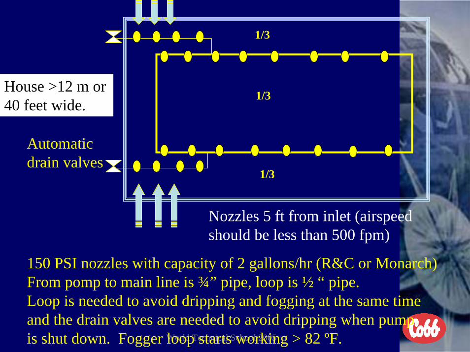
Automaticdrain valves
House >12 m or 40 feet wide.
1/3
1/3
1/3
Nozzles 5 ft from inlet (airspeed should be less than 500 fpm)
150 PSI nozzles with capacity of 2 gallons/hr (R&C or Monarch)From pomp to main line is ¾” pipe, loop is ½ “ pipe.Loop is needed to avoid dripping and fogging at the same time and the drain valves are needed to avoid dripping when pumpis shut down. Fogger loop starts working > 82 ºF.

World Technical School 2005
Automaticdrain valves
House >15 m or 49 feet wide.
by thermostat and opens > 85 ºFSolenoid valve controlled
Nozzles 5 ft from inlet (airspeed should be less than 500 fpm)
150 PSI nozzles with capacity of 2 gallons/hr (R&C or Monarch)From pomp to main line is ¾” pipe, loop is ½ “ pipe.Loop is needed to avoid dripping and fogging at the same time and the drain valves are needed to avoid dripping when pumpis shut down. Fogger loop starts working > 82 ºF.

World Technical School 2005
FORMULA FOR FIGURING INLET AREA BASED ON HOUSE
PRESSURE AND/OR WIDTH OF THE HOUSE
• THE HOUSE WIDTH SHOULD DETERMINE THE PRESSURE DROP YOU USE FOR BEST RESULTS AND TO FIGURE INLET SPACE FOR BEST DISTRIBUTION OF AIR THOUGH THE HOUSE
• EXAMPLES OF PRESSURE DROPS USED • PRESSURE -INLET SPACE -WIDTH OF HOUSE--AIR SPEED• .03 1 SQ.IN. 4.0 CFMS 10.4 M 34 F 700 FPM• .04 1 SQ.IN. 4.5 CFMS 10.9 M 36 F 800 FPM• .05 1 SQ.IN. 5.0 CFMS 12.2 M 40 F 900 FPM• .06 1 SQ.IN. 5.5 CFMS 13.7 M 45 F 1000 FPM• .07 1 SQ.IN. 6.0 CFMS 15.2 M 50 F 1100 FPM• .08 1 SQ.IN. 6.5 CFMS 18.3 M 60 F 1200 FPM• ** 144 square inches in one square foot
World Technical School 2005
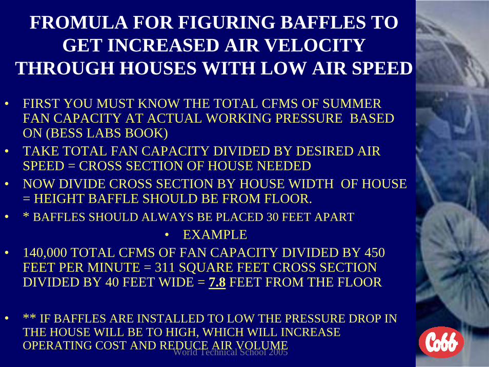
FROMULA FOR FIGURING BAFFLES TO GET INCREASED AIR VELOCITY
THROUGH HOUSES WITH LOW AIR SPEED
• FIRST YOU MUST KNOW THE TOTAL CFMS OF SUMMER FAN CAPACITY AT ACTUAL WORKING PRESSURE BASED ON (BESS LABS BOOK)
• TAKE TOTAL FAN CAPACITY DIVIDED BY DESIRED AIR SPEED = CROSS SECTION OF HOUSE NEEDED
• NOW DIVIDE CROSS SECTION BY HOUSE WIDTH OF HOUSE = HEIGHT BAFFLE SHOULD BE FROM FLOOR.
• * BAFFLES SHOULD ALWAYS BE PLACED 30 FEET APART• EXAMPLE
• 140,000 TOTAL CFMS OF FAN CAPACITY DIVIDED BY 450 FEET PER MINUTE = 311 SQUARE FEET CROSS SECTION DIVIDED BY 40 FEET WIDE = 7.8 FEET FROM THE FLOOR
• ** IF BAFFLES ARE INSTALLED TO LOW THE PRESSURE DROP IN THE HOUSE WILL BE TO HIGH, WHICH WILL INCREASE OPERATING COST AND REDUCE AIR VOLUME

World Technical School 2005
BAFFLESEVERY 30 F-9 M DOWN THROUGH THE HOUSE
STRICT CALCULATED DISTANCE

World Technical School 2005
Formula For Figuring Light Traps For Blackout Rearing Houses
• AT FAN AREA OF THE HOUSE TAKE THE TOTAL FAN CAPACITY AT 0.15 PRESSURE DROP DIVIDED BY 4 = SQUARE INCHES OF LIGHT TRAPS NEEDED -- NOW DIVIDE BY THE SIZE OF THE LIGHT TRAP TO BE USED = TOTAL NUMBER OF LIGHT TRAPS NEEDED (When possible place light traps on solid wall 3 feet from fans)
• AT THE INLET AREA OF THE HOUSE TAKE THE TOTAL FAN CAPACITY AT 0.15 PRESSURE DROP DIVIDED BY 5 = SQUARE INCHES OF LIGHT TRAPS NEEDED – NOW DIVIDE BY THE SIZE OF THE LIGHT TRAP TO BE USED= TOTAL NUMBER OF LIGHT TRAPS NEEDED
• * WITH THE EXCEPTION OF MINIMUM VENTILATION FANS NEVER INSTALL A LIGHT TRAP OVER A FAN IF POSSIBLE
• ** LIGHT TRAPS SHOULD ALWAYS BE INSTALLED A MINIMUM OF ¼ THE DIAMETER OF THE FAN AWAY FROM THE FANS

World Technical School 2005
EXAMPLE FOR FIGURING LIGHT TRAPS FOR BLACKOUT REARING HOUSES
• FAN AREA OF THE HOUSE HOUSE• 3 Fans X 21,500 cfms each = 64,500 total cfms divided by 4 =16,125
square inches of traps needed divided by 4,096 (64 X 64 inch trap) = 3.96 traps (4 traps needed)
• INLET AREA OF THE HOUSE• 3 Fans X 21,500 cfms each = 64,500 total cfms divided by 5 = 12,900
square inches of traps needed divided by 4,096 (64 X 64 inch trap) = 3.15 traps (3 traps needed)
• *When placing light trap over evaporative cooling pads since the length is fixed the height of the pads only has to be what is necessary to get the total square inches needed.

World Technical School 2005
400 fpm400 fpm
900 fpm900 fpm
Dog House Design Installation Cooling Pads and Light Traps
36 INCHES
Automatic Inlet Machine
Triple Hemmed Curtain
Inlet Light Trap
Evaporative CoolingPads

World Technical School 2005
900 fpm900 fpm
Inlet Light Trap Installation No Pads
Automatic Inlet Machine
Triple Hemmed Curtain
Inlet Light Trap

World Technical School 2005
Criteria For Selecting Fans1. Cfm ratings at actual operating pressure drop2. Energy factor CFM/WATT3. Shutter should always be behind fan (pull open)4. All negative pressure fans should have slant wall housing5. All negative pressure fans should have discharge cones6. All fans above 36 inch should be belt drive7. Unless a specific need, all fans should be fixed volume8. Quality control of fan from fan supplier9. All belt drive fans above 36 inch should have automatic belt
tightness adjusters10. Purchase price of fan to be used
** Based on BESS LABS FAN MANUAL

World Technical School 2005
EXAMPLE OF A POOR 36 INCH(91 cm) FAN
• STATIC PRESSURE SPEED AIRFLOW EFFICIENCY• IN. WATER RPM CFM CFM/WATT
• 0.00 863 9,780 21.0• 0.05 859 9,090 18.7• 0.10 855 8,400 16.2• 0.15 848 7,590 13.9• 0.20 844 6,680 11.7• 0.25 836 5,640 9.3• 0.30 828 4,420 7.0

World Technical School 2005
EXAMPLE OF A GOOD 36 INCH (91cm) FAN
• STATIC PRESSURE SPEED AIRFLOW EFFICIENCY• IN. WATER RPM CFM CFM/WATT
• 0.00 740 12,570 19.6• 0.05 784 11,680 17.4• 0.10 772 10,630 15.1• 0.15 762 9,510 13.2• 0.20 754 7,990 10.7• 0.25 757 6,520 8.9• 0.30 764 4,260 6.0

World Technical School 2005
EXAMPLE OF A GOOD 48 INCH (122cm) FAN
• STATIC PRESSURE SPEED AIRFLOW EFFICIENCY• IN. WATER RPM CFM CFM/WATT
• 0.00 473 23,800 22.5• 0.05 472 22,700 20.6• 0.10 471 21,600 19.0• 0.15 470 20,300 17.2• 0.20 470 18,600 15.4• 0.25 469 16,700 13.6• 0.30 468 14,100 11.0

World Technical School 2005
EXAMPLE OF A POOR 48 INCH (122cm) FAN
• STATIC PRESSURE SPEED AIRFLOW EFFICIENCY• IN. WATER RPM CFM CFM/WATT
• 0.00 530 19,000 19.8• 0.05 530 17,800 18.1• 0.10 528 16,500 16.2• 0.15 528 14,900 14.3• 0.20 525 12,500 12.0• 0.25 525 9,500 8.5• 0.30 523 6,100 4.9

World Technical School 2005
EXAMPLE OF A GOOD 50 INCH(127 cm) FAN
• STATIC PRESSURE SPEED AIRFLOW EFFICIENCY• IN. WATER RPM CFM CFM/WATT• 0.00 587 28,500 24.4• 0.05 585 26,800 21.7• 0.10 583 24,600 19.0• 0.15 582 22,300 16.7• 0.20 582 17,800 13.2• 0.25 584 15,800 12.6• 0.30 587 10,900 10.6

World Technical School 2005
EXAMPLE OF A GOOD 52 INCH (132 cm) FAN
• STATIC PRESSURE SPEED AIRFLOW EFFICIENCY• IN. WATER RPM CFM CFM/WATT• 0.00 650 29,600 26.3• 0.05 649 27,900 23.2• 0.10 648 26,400 20.7• 0.15 646 24,700 18.5• 0.20 645 22,800 16.3• 0.25 643 20,500 14.2• 0.30 642 18,000 12.0

World Technical School 2005
Example of good smaller fans at .10 inches of water pressure drop.
– Static pressure Speed Airflow Efficiency– In. water RPM CFM cfm/watts
• 36 inch .10 633 11,200 17.1• 24 inch .10 1086 6,500 12.0• 18 inch .10 1412 2,060 11.3• 16 inch .10 1605 2,330 10.9• 14 inch .10 1566 1,500 10.2• 12 inch .10 1661 1,150 9.6• 10 inch .10 3422 1,130 5.8
• All these numbers are based on the fans running at 100% capacity on full voltage.

World Technical School 2005
All Panel Fans Rated @ 20,000cfm at Zero Pressure
PANEL FAN ONLY PANEL FAN WITH SHUTTER ON FRONT
Head Pressure + Negative Pressure
Operating cost increasesby 15%.

World Technical School 2005
All Panel Fans Rated @ 20,000cfm at Zero Pressure
PANEL FAN WITH SHUTTERBEHIND FAN
SLANTWALL FAN SHUTTERBEHIND FAN
Air still has to change directions.
Fan installed at same angle that shutter opens.
Cost to operate goes back down 10%
Cost to operate goes down 5%.

World Technical School 2005
All Panel Fans Rated @ 20,000cfm at Zero Pressure
STRAIGHT WALL CONE FAN SLANT WALL CONE FAN
Cone relieves pressure drop.
Air still has tochange directions.
Cone relievesPressure drop.
Fan installed at same angle as shutter opens.
25% reductionin cost to operate.
33% reduction incost to operate.

World Technical School 2005
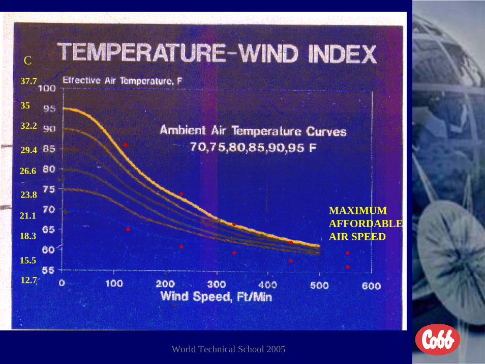
EFFECTIVE TEMPERATURE
• DRY BULB TEMPERATURE WITH RELATIVE HUMIDITY AND AIR SPEED (WIND CHILL INDEX ) ACROSS THE BIRDS FACTORED INTO THE EQUATION

World Technical School 2005
EFFECTIVE TEMPERATURES CHART• ACTUAL TEMPERATURE RELATIVE HUMIDITY AIR VELOCITY FEET PER
MINUTE• F° C° 50% 70% 0 100 200 300 400 500• 95 * 95+ 90 80 76 74 72• 35 * 35 32.2 26.6 24.4 23.3 22.2• 95 * 101 96 87 84 79 76• 35 * 38.3 35.5 30.5 28.8 26.1 24.4• 90 * 90+ 85 78 75 73 70• 32.2 * 32.2 29.4 25.5 23.8 22.7 21.1• 90 * 96 91 84 81 78 74• 32.2 * 35.5 32.7 28.8 27.2 25.5 23.3• 85 * 85+ 80 76 73 70 68• 29.4 * 29.4 26.6 24.4 22.8 21.1 20.0• 85 * 89 86 81 78 76 74• 29.4 * 31.6 30 27.2 25.5 24.4 23.3• 80 * 80+ 76 72 70 66 65• 26.6 * 26.6 24.4 22.2 21.1 18.9 18.3• 80 * 83+ 79 76 74 69 67• 26.6 * 28.3 26.1 24.4 23.3 20.5 19.4• 75 * 75+ 73 70 68 64 62• 23.9 * 23.9 22.8 21.1 20 17.7 16.6• 75 * 78 76 74 72 68 66• 23.9 * 25.5 24.4 23.3 22.2 20 18.8• 70 * 70+ 66 65 64 62 61• 21.1 * 21.1 18.9 18.3 17.7 16.6 16.1• 70 * 74 69 67 66 65 63• 21.1 * 23.3 20.5 19.4 18.8 18.3 17.2

World Technical School 2005
EFFECTIVE TEMPERATURES 85-95°F (29.4-35°C)
• ACTUAL TEMPERATURE RELATIVE HUMIDITY AIR VELOCITY FEET PER MINUTE• F C 30% 50% 70% 80% 0 100 200 300 400 500
95 * 95 89 79 75 73 7235 * 35 31.6 26.1 23.8 22.7 22.2
• 95 * 95+ 90 80 76 74 72• 35 * 35+ 32.2 26.6 24.4 23.3 22.2• 95 * 101 96 87 84 79 76• 35 * 38.3 35.5 30.5 28.8 26.1 24.4• 95 * 104 99 89 86 81 78• 35 * 40 37.2 31.6 30 27.2 25.5• 90 * 90 84 77 73 71 68• 35 * 37.2 35 30 27.7 27.2 26.1• 90 * 90+ 85 78 75 73 70• 32.2 * 32.2 29.4 25.5 23.8 22.7 21.1• 90 * 96 91 84 81 78 74• 32.2 * 35.5 32.7 28.8 27.2 25.5 23.3• 90 * 99 95 86 82 81 79• 32.2 * 37.2 35 30 27.7 27.2 26.1• 85 * 85 79 75 72 69 67• 29.4 * 29.4 26.1 23.8 22.2 20.5 19.4• 85 * 85+ 80 76 73 70 68• 29.4 * 29.4 26.6 24.4 22.8 21.1 20.0• 85 * 89 86 81 78 76 74• 29.4 * 31.6 30 27.2 25.5 24.4 23.3• 85 * 92 89 84 80 77 75• 29.4 * 33.3 31.6 28.8 26.6 25 23.8

World Technical School 2005
EFFECTIVE TEMPERATURES 70- 80° (21.1-26.6°C)
• ACTUAL TEMPERATURE RELATIVE HUMIDITY AIR VELOCITY FEET PER MINUTE• F C 30% 50% 70% 80% 0 100 200 300 400 500• 80 * 80 75 71 69 64 64
26.6 * 26.6 23.8 21.6 20.5 17.7 17.780 * 80+ 76 72 70 66 65
• 26.6 * 26.6 24.4 22.2 21.1 18.9 18.3• 80 * 83+ 79 76 74 69 67• 26.6 * 28.3 26.1 24.4 23.3 20.5 19.4• 80 * 85 81 78 75 70 69• 26.6 * 29.4 27.2 25.5 23.8 21.1 20.5• 75 * 75 72 69 67 62 62 • 23.9 * 23.8 22.2 20.5 19.4 16.6 16.6• 75 * 75+ 73 70 68 64 62• 23.9 * 23.9 22.8 21.1 20 17.7 16.6• 75 * 78 76 74 72 68 66• 23.9 * 25.5 24.4 23.3 22.2 20 18.8• 75 * 79 77 75 73 69 68• 23.9 * 26.1 25 23.8 22.7 20.5 20• 70 * 70 66 64 63 62 60• 21.1 * 21.1 18.9 17.7 17.2 16.6 15.5• 70 * 70+ 66 65 64 62 61• 21.1 * 21.1 18.9 18.3 17.7 16.6 16.1• 70 * 74 69 67 66 65 63• 21.1 * 23.3 20.5 19.4 18.8 18.3 17.2 • 70 * 76 71 68 66 66 65• 21.1 * 24.4 21.6 20 18.8 18.8 18.8

World Technical School 2005
EFFECTIVE TEMPERATURE
A. TEMP. RH AIR SPEED E. TEMP.
80F 50% 0 82F80F 70% 0 86F80F 50% 400 66F80F 70% 400 69F

World Technical School 2005
EFFECTIVE TEMPERATURE
CONTINUES
A. TEMP. RH AIR SPEED E. TEMP.
95F 50% 0 97F95F 70% 0 101F95F 50% 400 74F95F 70% 400 79F

World Technical School 2005
IDEAL EFFECTIVE TEMPERATURES FOR BEST RESULTS
• BROILER BREEDER 65°F (18.3°C) 50% RH• Equivalent 82° F (27.8°C) DB 400 FPM air 50% RH• Air exchange must be less than 1.2 minutes.
• BROILERS 65° TO 70° F (18.3°-21.1°C) 50% RH• Equivalent 85° F (29.4°C) DB 500 FPM air 50% RH• Air exchange must be less than 1.2 minutes.
• BLACKOUT REARING 75° F (23.9° C) 50% RH• Equivalent 85° F (29.4°C) DB 350 FPM air 50% RH• Air exchange must be less than 1.3 minutes.
• ** DB – Dry Bulb temperature

World Technical School 2005
IDEAL EFFECTIVE TEMPERATURES
• LAST SUMMER FANS SHOULD BE RUNNING BY 78° F (25.5°C)
• PUMPS ON COOLING SYSTEM SHOULD NOT RUN BELOW 80° F (26.7° C) (82° F (27.8°C) is recommended)
• THERE SHOULD BE 4°F (2°C) BETWEEN LAST FANS AND PUMPS RUNNING
• PUMPS ON COOLING SYSTEMS SHOULD RUN BASED ON A COMBINATION OF TEMPERATURE AND RELATIVE HUMIDITY
World Technical School 2005
MAXIMUMAFFORDABLEAIR SPEED
37.7
35
C
32.2
29.4
26.6
23.8
21.1
18.3
15.5
12.7
.
.
.
..
.
.
...

World Technical School 2005
HEAT STRESS NUMBERES
• ADD DRY BULB TMPERATURE IN FAHRENHEIT AND RELATIVE HUMIDITY TOGETHER TO GET STRESS INDEX NUMBER TO WORK WITH.
• WHEN THE SUM OF THE TOTAL IS• 150 OR LESS NO PROBLEM• 155 ON BORDERLINE OF PROBLEMS• 160 OFF FEED, INCREASE WATER INTAKE, PRODUCTION
LOSS. • 165 SAME AS 160 WITH FIRST MORTALITY• 170 SAME AS 160 WITH HIGH MORTALITY

World Technical School 2005
Temperature And Humidity As It Relates To Heat Stress Index Numbers
• There should be a spread of 25° F between relative humidity and dry bulb temperature for chickens to remain within their thermal neutral zone for comfort and performance anytime the temperature reaches90°F.
DP 170TEMPERATURE 165
160155
RH 150As the relative humidity continues to increase and the levelbegins to get closer to the dry bulb temperature level the heatstress index number becomes higher. The higher the indexnumber the more the birds will suffer and the more performancewill be loss and eventually there will be heat prostration mortality.

World Technical School 2005
Chickens Thermal Neutral Zone st ated e a eut a o e
55
60
65
70
75
8085
90
95
0.13
0.25
0.43
0.65
0.92
1.23
1.59
1.99
2.43
2.89
3.36
3.84
4.33
4.83
5.34
5.86
6.39
6.91
7.44
Weight (pounds)
Tem
pera
ture
(oF) 35
32
29.4
26.6
23.8
21.118.3
15.512.7
7 14 21 28 35 42 49 56DAYS
C°

World Technical School 2005
Heat Stress Numbers
90 85 80 75 70 65 60 55 50 45 40 35 3090/32.2
92
9496/35.5
98100
102/38.9104
100
110
120
130
140
150
160
170
180
190
200
Heat stress no.
RH (%)
Dry bulb temp. (deg.F)
190-200
180-190
170-180
160-170
150-160
140-150
130-140
120-130
110-120
100-110
9090°° + 75% = 165+ 75% = 1659595°° + 60% = 155+ 60% = 155*90*90°° + 80% = 170+ 80% = 170*80*80°° + 90% = 170+ 90% = 170
Temp.Temp.°° F + RH%F + RH%170 170 -- High mortalityHigh mortality165 165 -- First mortalityFirst mortality160 160 -- Loss efficiencyLoss efficiency155 155 -- BorderlineBorderline150 150 -- AcceptableAcceptable
*Temperature and Humidity Switch - Results The Same

World Technical School 2005
Temperature and Humidity Daily OccurrenceThis graft covers from midnight to midnight on a daily basis in most areas of the world.Twice each day in most seasons and most countries the dew point (DP) is reached.
Late AfternoonMid Morning
DPDP
A 85%Of All
B Heat ProstrationMortality Occurs
Line A (red) is temperature and there is a gradual increase to a point then it begins togo back down. Line B (blue) is relative humidity increases to dew point early morning and again in thelate afternoon.From mid morning back to midnight the dry bulb temperature is not high enough tocreate a problem. From mid morning until late afternoon there is enough spreadbetween dry bulb and humidity not to create a problem. Once the temperature beginsto go down and the humidity begins to increase is normally when the problem occursand mortality goes up.

World Technical School 2005
Heat Stress Index Numbers Too High
• You can never overrun pumps on cooling system trying to lower the dry bulb temperature at the expense of elevating the relative humidity too high.
• Insulation in the top of the house inadequate.• Hot air leaking through ridge cap, over the top of the curtains, or
under the curtains.• Bird density too high for capability of ventilation system.• Wind speed through the house across the birds too low.• Pad surface area does not match capacity of fans at actual
working pressure.• Pads need clean and/or replacing.• Leaks between and around evaporative cooling pads.

World Technical School 2005
Recommended Ventilation System Broiler Breeders
1. Tunnel ventilation with evaporative cooling pads and minimumventilation cool to moderate climates. In hot climates minimum ventilation may not be necessary.
2. Tunnel ventilation with foggers and minimum ventilation.
• All minimum ventilation should be across the house unless the house is lessthan 250 feet (76 meters) long.
• All pumps on cooling systems should run based on temperature andhumidity combination. (THO)

World Technical School 2005
Recommended Ventilation SystemsBlackout--Rearing
• Tunnel ventilation with foggers and minimum ventilation. Minimum ventilation inlets should be air cannons and VF48 -TJP2600 second stage inlets with light traps. Fan area of the house must have 1 square inch of light trap for every 4 cfms of fan capacity. Inlet area of the house must have 1 square inch of light trap for every 5 cfms of fan capacity. Foggers should be uniformly distributed through out the house and operated with a (THO) control.
• Cooling pads are optional but hard to justify for parent stock birds.
• All minimum ventilation should be across the house unless the house is lessthan 250 feet (76 meters) long.

World Technical School 2005
Recommended Ventilation SystemsBroilers
1. Tunnel ventilation with foggers and minimum/transition ventilation.2. Tunnel ventilation with evaporative cooling and minimum/transition
ventilation. 3. Open wall houses with fans in sidewall at a 60 degree angle with
foggers and minimum ventilation.4. Tunnel ventilation with fogger pads and minimum/transition
ventilation. Only if pad space is adequate (total fan volume atworking pressure ÷ 150) and the pumps are run based on temperature and humidity combination. (THO)
• All minimum ventilation should be across the house unless the house is less than 250 feet (76 meters) long. All fogger pumps should run based on temperature and humidity. (THO)

World Technical School 2005
TROUBLE SHOOTING CONDITIONS
• PREVENTIVE MAINTENANCE• LOCATION AND ACCURACY OF TEMPERATURE/HUMIDITY
PROBES (Relative humidity probe should be located on the inlet end of the house in the first 25% of the house (4 feet off the floor). The temperature should be averaged evenly through the house or at the fan end of the house (probes should be located at bird level).)
• SET UP AND CALIBRATION OF ENVIRONMENTAL CONTROLS MUST BE ACCURATE
• RELATIVE SET POINTS FOR CONDITIONS, AGE, AND SIZE OF BIRDS
• ACCURACY OF INLET PRESSURE BASED ON WIDTH OF THE HOUSE
• OBSERVE COMFORT AND REACTION OF THE BIRDS• ADEQUATE AVALIABILITY OF FEED AND WATER SPACE• CONDITION OF LITTER

World Technical School 2005
Doing the Right Things...Doing the Right Things...FOR SUMMER VENTILATION
Maximum ventilation - to control heat load, e.g. tunnel system
Ventilation Design, Installation, and Management

World Technical School 2005
Doing the Right Things...Doing the Right Things...
Ventilation Design, Installation, and Management
For Housing
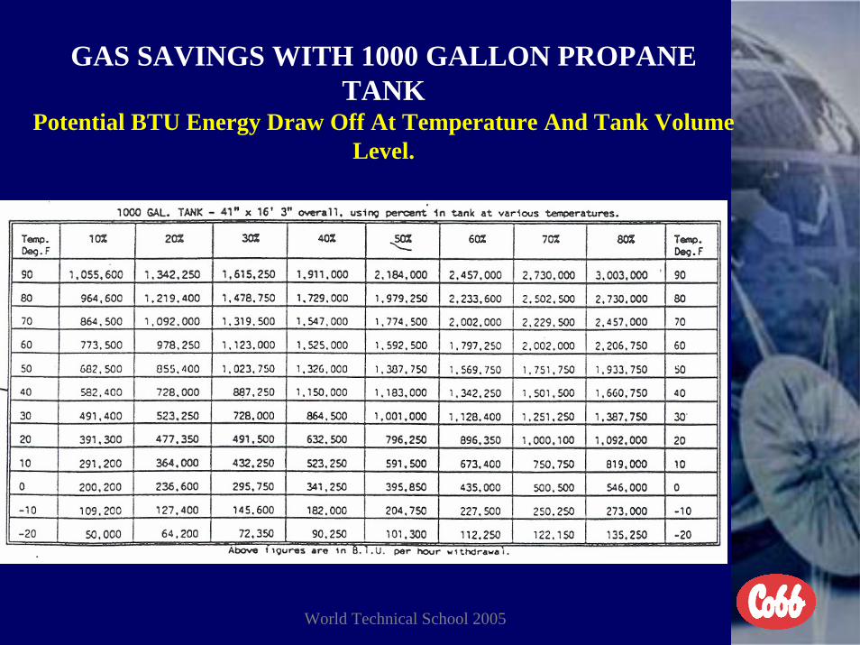
World Technical School 2005
GAS SAVINGS WITH 1000 GALLON PROPANE TANK
Potential BTU Energy Draw Off At Temperature And Tank Volume Level.
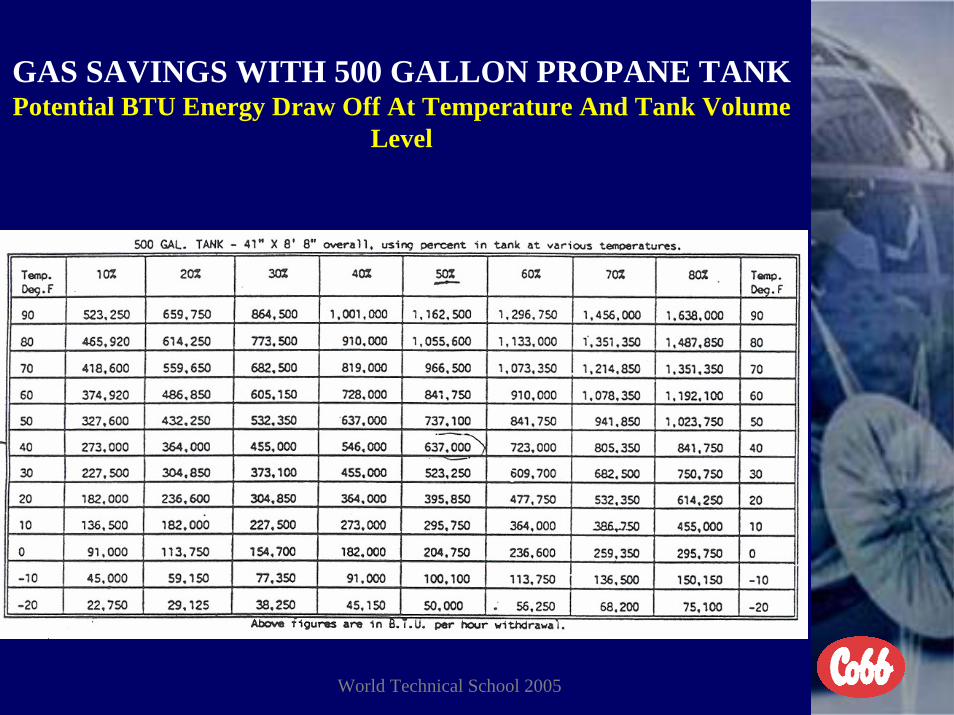
World Technical School 2005
GAS SAVINGS WITH 500 GALLON PROPANE TANKPotential BTU Energy Draw Off At Temperature And Tank Volume
Level

World Technical School 2005
COMFORTABLECOBB 500 CHICKENS

World Technical School 2005
THE ENDTHANKS FOR ALLOWING COBB-VANTRESS THE OPPORTUNITY TO TAKE PART IN THIS MEETING.
PLEASE COME BACK AND VISIT AGAINTHANKS FOR THE BUSINESS