using meta-modeling in design and implementation of...
TRANSCRIPT
Using meta-modeling in design and implementation of component-based
systems: the SOFA case-study
Petr Hnětynka1 and František Plášil
1,2
1Department of Software Engineering
2Institute of Computer Science
Charles University Academy of Sciences of the CzechRepublic
Malostranské náměstí 25 Pod Vodárenskou věž
Prague 1, 11800, Czech Republic Prague 8, 18000, CzechRepublic
{hnetynka, plasil}@dsrg.mff.cuni.cz [email protected]
Abstract:
To allow efficient and user-friendly development of a component-based application, component
systems have to provide a rather complex development infrastructure, including a tool for
component composition, component repository, and a runtime infrastructure. In this paper, we
present and evaluate benefits of using meta-modeling during the process of defining a component
system and also during creation of the development and runtime infrastructures. Most of the
presented arguments are based on a broad practical experience with designing the component
systems SOFA and SOFA 2; the former designed in a classical ad hoc “manual” way, while the
latter with the help of meta-modeling. Keywords: Software architectures, software components, model-driven development, meta-
models, model transformation, ADL
1 Introduction
Component-based development (CBD) has become a well-understood and widely used
technique for developing not only large enterprise software systems, but a whole spectrum of
other applications, since it offers a faster and more flexible development process than the
classical techniques. Recently, this spectrum includes also embedded applications and even real-
time embedded systems (e.g. the CORDET project [1] – Component Oriented Development
Techniques – funded by ESA, which aims at providing a generic component architecture for
satellite on-board software applications). Another advantage of CBD, especially important for the
embedded applications, is the support of Software Product Lines (SPL) [2], as software
components allow separating development of a component-based architecture and the actual
component implementations [3]. A closely related technique to CBD is service-oriented
development and architecture (SOA). The general goal of CBD and SOA is similar – to build
software from reusable blocks; however SOA focuses on services’ interfaces and composition
based on independently deployed components, with less emphasis on their actual implementation.
Using CBD, applications are built by composing software components, both the ones
designed in an ad-hoc manner to fulfill a very specific task, and the generic ones intended for
reuse. Every component system (i.e., a system and/or framework for developing, composing,
deploying, and running components) applies a different view as to what a software component is;
nevertheless the generally agreed consensus is that the term “component” means a black-box or
glass box entity with well-defined interfaces and, assuming it runs in an environment of specific
properties, exhibiting pre-defined behavior. The interfaces of a component comprise the services
it provides and also the services it requires from its environment (container, cooperating
components). A component system is based on its component model, which specifies all the involved entities with their semantics, i.e. the set of abstractions and their relationships which
form a component, the rules for component composition, deployment, run-time containers, etc.

Therefore, the term “component” has to be always interpreted in the scope of a particular
component model.
In order to allow a truly efficient and user-friendly development of component-based
applications, component systems should provide a rather comprehensive development
infrastructure (platform integrating related software tools). Such a platform usually comprises (at
least) a tool for component development and composition and a repository for storing and
retrieving the already available components. Moreover, if a component system supports the
whole application lifecycle from design to deployment and execution, a run time infrastructure
(chiefly containers and middleware) has to be built as well.
However, creating such an infrastructure is rather tedious and time- and resource-consuming
task. This is probably why the early component systems, mostly academia-based, provided no, or
very limited support for development of components at a large scale [4, 5, 6], in spite of being
based on sophisticated component models with plenty of advanced features. The component
models of these early (“classical”) component systems were defined with the help of the concrete
syntax of an ADL (Architecture Definition Language). Typically, a number of in principal
syntactical constraints and also associations among particular abstractions were specified in
natural language which made it very hard to develop both the design and run-time infrastructures
in an automated way; therefore they were typically created ad hoc, mostly from scratch,
potentially with partial reuse of an existing middleware.
Moreover, since component models frequently share similar core, a natural desire is to
achieve interoperability between the models to make component reuse easier and allow for
development and management of heterogeneous applications. Obviously, with an ad-hoc
developed infrastructure, achieving interoperability was quite difficult (as we experienced when
converting SOFA components to Fractal components in the CoCoME application [7, 8]).
In order to overcome these problems, in the current component systems, such as [9],[10], and
[11], modeling and meta-modeling methods were employed that allow automated generation of
many tools in the desired infrastructures.
1.1 Goal and structure of the paper
The goal of this paper is to describe an approach of using meta-models and model-driven
development in designing component systems and to present pros and cons of this method. The
supporting arguments are based on our experience with designing and developing the component
systems SOFA [12] and SOFA 2 [11], and on an analysis of other component systems, such as
Fractal [13], Palladio[10] and ProCom [14]. We argue that the model-driven approach fosters an
easy and efficient creation of a component system. To justify our claims, we evaluate and
compare the model-driven approach with the traditional one by comparing the design of
component models SOFA (traditional) and SOFA 2 (based on meta-model). Moreover, stemming
from these SOFA case studies, the paper aims at a comparison between traditional development
of an infrastructure (a repository, modeler, runtime infrastructure) and (semi) automated
generation of it by formalizing an ADL as a meta-model and adopting a generic modeling
platform EMF [15]. This paper is a substantial extension of the paper [16] with strong emphasis
on the experience gained during design and development of both SOFA and SOFA 2; it also
provides a comprehensive quantitative information on all the meta-models involved in this
process.
To achieve the goal, the paper is structured as follows. Section 2 presents an overview of
meta-modeling principles and component models and their development tools and infrastructure.
In Section 3, we articulate the benefits of using meta-models for component system specification
and implementation of the supporting infrastructures. Section 4 compares the SOFA and SOFA 2
design process and, based on the comparison, analyzes the benefits of meta-modeling in this
context. Section 5 concludes the paper.
2 Background
2.1 Models and meta-models
Model and meta-model are the main concepts of model-driven development (MDD) [17],
currently a popular development paradigm. In MDD, an application is developed via a chain of
models. A typical approach starts with modeling the application at a platform independent level
to capture only the business logic, leaving out implementation details. In a series of
transformations, this platform independent model is then refined into a platform specific model,
reflecting the details specific for the platform chosen for implementation (such as Java and .NET).
The abstractions featuring in a model (its elements) are described by a meta-model, i.e. a
model of the model. Often, the meta-model is referred to as a “domain specific language” (DSL),
since it defines the means for modeling applications in a specific domain. Strictly speaking, DSL
is a particular realization of the meta-model, or, in other words, as a concrete syntax of the meta-
model (the meta-model determines “abstract syntax”).
For meta-models, OMG published the Meta-Object Facilities (MOF) standard [18]. It defines
a language and framework for specifying and constructing meta-models and for implementing the
repositories storing instances of the corresponding models. Nevertheless, the current de-facto
standard for creating meta-models is the Eclipse Modeling Framework (EMF) [15]. It can be seen
as an implementation of the MOF standard, even though it does not rigorously comply with this
standard, allowing for a more flexible modeling hierarchy than the strict 4-layer hierarchy in
MOF; the main ideas are the same, though, and, from the user perspective, there is no practical
difference. In the rest of the paper, we use EMF and stick with its terminology.
Being a well supported, maintained, and open source Eclipse plugin, EMF is very popular. In
EMF, a meta-model is typically specified with a subset of the UML class diagrams. The primary
meta-modeling elements are class (defining abstractions) and association1 (defining relationships
among classes). For illustration, Figure 2 shows a tiny subset of the core of the SOFA 2 meta-
model (details are explained in Section 3.1).
Once a meta-model is available, a repository for storing models (instances of the meta-
model) can be generated in an automated way. Such a repository offers a straightforward API
(e.g., for each class of a model, there are get/set methods for all attributes and associations). In its
default variant, the repository stores models in local files complying with XMI format [18] so
that interchange between different repositories is guaranteed. Models can be also stored in a
relational database (which makes the repository accessible remotely) or in a user-defined way.
The interface of the generated repository offers reflection, so that generic clients like browsers
can be used with the repository.
Furthermore, EMF can generate a semi-visual tree-based editor of models. Even though the
editor is very simple, it guarantees creation and linking of the abstraction instances only in a way
1 To be precise, they should be referred to as meta-classes and meta-associations (since they are a part of meta-
model) but for the sake of simplicity, we use only the terms classes and associations in this paper.

compliant with the corresponding meta-model. Figure 3Figure 3 shows a screenshot fragment of
such an editor for SOFA 2.
Based on EMF, the Graphical Modeling Framework [19] (GMF) is available for generating
modelers (visual editors) from the meta-models developed in EMF. Moreover, such visual editors
can further serve as the basis for creating a variety of other tools comprised in an infrastructure.
A simplified process of creating a GMF-based visual editor is depicted on Fig. 1. In addition to
the meta-model, the following information has to be specified to generate an editor (i) the style of
visual representation of each model element (i.e. of classes and associations), (ii) a toolbar
(”palette”) for selecting model elements, (iii) a mapping between meta-model elements, visual
representation, and palette. Technically, the editor can be installed as a part of the Eclipse IDE, or
configured to run as a standalone application built over the core of Eclipse.
Meta-model
Visualrepresentation
Elementpalette
Mapping
visual editor
Figure 1 GMF principle and workflow
A necessary prerequisite for successful use of models and meta-models in design and
development is a support for model transformations, which is in MDD realized by transformation
specification languages. For that purpose, OMG standard [20] defines the language called QVT
(Query-View-Transform). QVT allows performing queries on model elements, and defining
model transformations. Technically, QVT offers a declarative and imperative specification of
transformations (currently only the imperative specifications are supported by EMF). Another
option is ATL (ATLAS Transformation Language) [21]. Compared to QVT, ATL offers more
mature implementation; however, it is not standardized. On the other hand, there is a way to
make these two languages interoperable [22].
2.2 Component models employing meta-modeling
As mentioned in Section 1, to support fast and efficient development of a component-based
application, a component system has to provide a complex development infrastructure, which
should feature at least the functionality for component composition (defining the architecture of
the application) and a repository to store the already available components (both the generic and
specific ones). A more complex situation is in a component system targeting complete
component lifecycle when also a run-time infrastructure has to be provided.
There are a number of older component systems (like Darwin [4], Wright [5], ACME [6],
Koala [23]) that were not defined by an explicit meta-model and all tools and infrastructure were

implemented the traditional way. Furthermore, they usually did not cover the whole development
lifecycle, targeting design stage only. Nevertheless, some of such component systems were later
on re-specified, at least partially, by a meta-model. This category includes the CORBA
Component Model (CCM) [24] and Fractal [13] (both of them also support the whole component
lifecycle).
CCM was defined in the form of plain-English specification and IDL grammar. However,
the run-time infrastructure was later re-defined by the OMG Deployment and Configuration
(D&C) specification [25] via a set of meta-models; D&C determines a deployment environment
and also the role of several managers controlling deployment and execution. Moreover, being
rather generic and platform independent, this specification is not focused narrowly on CCM, even
though it already contains meta-models specific to CCM. Nevertheless, to be applied to another
specific system, the D&C generic meta-model has to be profiled accordingly.
Fractal [13] is a component model aiming at industrial applications. There are several
implementations (Fractal systems in our terminology), including two of them in Java [13, 26] and
one in C [27]. Components are primarily built at run-time using the API calls defined in the
Fractal specification. An ADL also exists as a “shortcut” for creating components and
architectures – an ADL specification is transformed into run-time API calls. The specification of
Fractal does not presume existence of any repository, but there are attempts to do so ([28]).
Originally, the supporting tools for each Fractal system were designed and written fully ad-hoc,
but currently a visual editor (component development tool) called F4E (developed as an Eclipse
plugin), has become available [28]. Large parts of the tool have been generated using EMF and
GMF.
SOFA and, especially, its new version SOFA 2, define a general purpose component system
based on Java. The SOFA system was defined with the help of a textual ADL and the repository
and all other tools were designed and written in a traditional way. On the other hand, SOFA 2 has
been redesigned via a meta-model allowing most of the supporting tools and the repository to be
implemented in an automated way via EMF and GMF. More details and comparison of both
approaches are discussed in Section 3.
The trend to define component systems via meta-models can also be observed in those
systems backed by the industry. For example, AADL [9], a component system for real-time
performance-critical systems, was originally defined by a textual specification. However, later, a
meta-model has been created and added as a part of the specification. Also, SCA [29] was
defined by a textual specification, but later, a meta-model was created in order to employ EMF
and GMF for creating supporting tools (even though the meta-model has not become a part of the
SCA specification though).
To the component systems that were designed via a meta-model from scratch belong
Palladio, PRISMA, and ProCom. Palladio [10] primarily focuses on architectural description-
based prediction of QoS (including simulation). As such, Palladio does not provide any runtime
environment, but there are tools generating EJB skeletons from Palladio components. The
Palladio meta-model is defined via EMF and all the related tools are generated with the help of
GMF. The PRISMA component system [30] describes software architectures by employing
concepts of aspect-oriented programming; an implementation of run-time environment is under
development (no further details are known currently). The meta-model is described in EMF and
development tools are generated. ProCom [14] targets embedded distributed systems. Its meta-
model is specified in EMF; an implementation of supporting tools has been reported, however no
details have been published so far. Even though the list of component systems mentioned above
is definitely not complete (especially of those designed in academia), it illustrates a common
trend to use meta-models in component system definition and to take advantage of automated
generation of supporting tools.
3 Applying meta-models in component model design and system implementation
In this section, we describe the key areas of benefits of meta-modeling in component system
design and development, which we identified during creation of the SOFA 2 component system.
These areas include (i) definition of the component model abstract and concrete syntax, (ii) semi-
automated creation of the development infrastructure, (iii) making component models (at least
partially) interoperable, and (iv) run-time support.
3.1 Defining abstract syntax of a component model
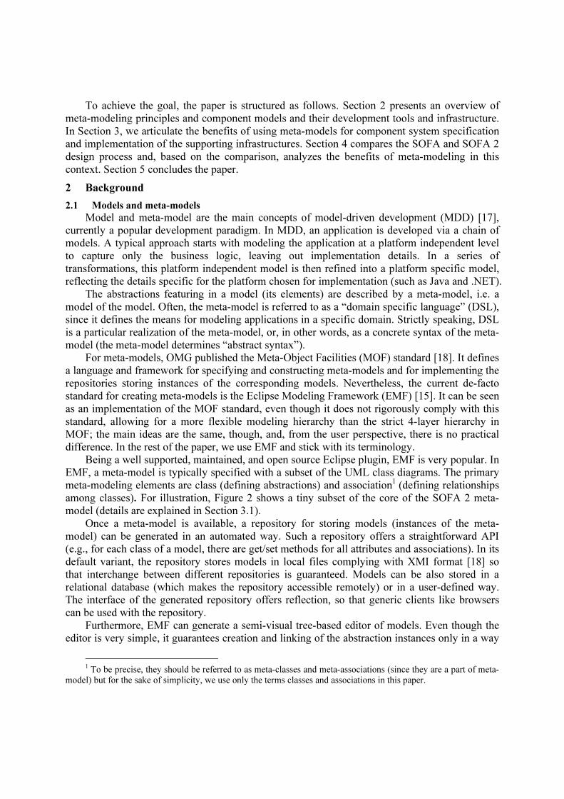
In a component model specification, the meta-model obviously defines the abstractions and
their relationships the component model is based upon.
Frame
Architecture
implements
InterfaceInterfaceType
type
0..*
providedInterface
0..*
requiredInterface
SubcomponentInstance0..*
subcomponent
instantiates
Binding
0..*
binding
Endpoint0..*
endpoint
Figure 2 Key abstractions of the SOFA 2 core meta-model
Figure 2Figure 2 shows a key subset of the core meta-model of the SOFA 2 component
system (a full-fledged part of the core meta-model related to components is in Appendix A). It
defines the key abstractions of SOFA 2: Frame (component type), Architecture (component
implementation), and InterfaceType. A frame provides black-box view of a component instance by
defining its provided and required interfaces, each of a specific interface type. The frame is
implemented by an architecture, which can contain instances of subcomponents (defined again by
frames) and bindings among these subcomponents. If the architecture does not have any
subcomponents, it determines a primitive component implementation which is to be provided in
an underlying programming language. Apart from components, the core meta-model also
describes so called micro-components [31], which define the management of component lifecycle
and extra-functional properties in a modular and declarative way, using principles of aspect-
oriented development (the micro-components related part of the core meta-model is in Appendix
B). At run-time, the instances of components are internally composed of instances of micro-
components.
Via classes and associations, the meta-model determines the abstract syntax of the
component model in an easy-to-comprehend way. A concrete syntax derived from the meta-
model then depends on the development infrastructure (Section 3.2).
The expressiveness of a meta-model can be further increased by adding constraints specified
e.g. in OCL (Object Constraint Language). For example, for Architecture, such a constraint might
be,: self.subcomponent->forAll(s1,s2 | s1.name<>s2.name – the names of subcomponents in the
architecture (determined by self) must be distinct. Satisfaction of these constraints can/should be
verified in each model instance.
The semantics of model elements (i.e. the meaning of the classes and their associations) is
typically defined in plain English, e.g. “Architecture is a component implementation”. On the
other hand, when using standard component terminology, a meta-model can be to a large extent
easily “readable” to those familiar with a semantically similar component model, even without
the need to study a detailed textual definition of the semantics. This is a sign of the fact that a
meta-model can easily express a number of detailed associations among the model’s abstractions
and this is where such component models actually differ.
To summarize, the meta-model and constraints provide a complex, but simple-to-use and
easy-to-understand standard formal means for expressing the abstractions and their relationships
of a component model. The expressive power of the abstract syntax provided by a meta-model is
much higher compared to the textual ADL syntax where a number of – in principal syntactical –
constraints and also associations among particular abstractions are typically to be specified in a
natural language
3.2 Creation of development infrastructure
The second important benefit of the meta-modeling approach is the semi-automated creation
of a development infrastructure. As we already noted, supporting tools are crucial for a successful
adoption of a component system.
As mentioned in Sect. 2.2, once the meta-model of a component system has been defined, it
is very easy to create the following development infrastructure: First, a repository for storing the
already developed components (i.e. the instances of components) can be generated. Furthermore,
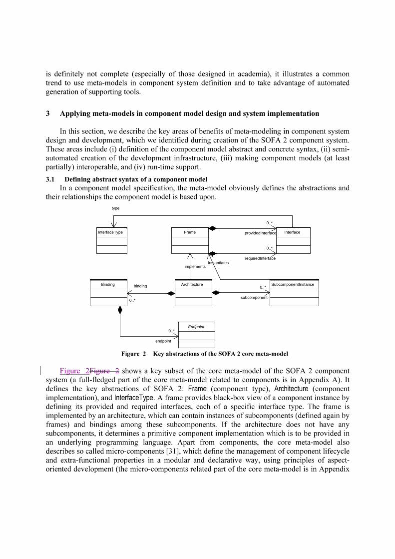
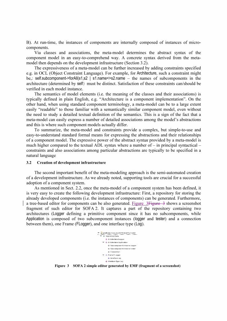
a tree-based editor for components can be also generated. Figure 3Figure 3 shows a screenshot
fragment of such editor for SOFA 2. It captures a part of the repository containing two
architectures (Logger defining a primitive component since it has no subcomponents, while
Application is composed of two subcomponent instances (logger and tester) and a connection
between them), one Frame (FLogger), and one interface type (Log).
Figure 3 SOFA 2 simple editor generated by EMF (fragment of a screenshot)

Moreover, with GMF, a more sophisticated visual editor for component design can be partially
generated. In Figure 4Figure 4, a screen shot of a GMF-based visual editor of SOFA 2 is shown.
Specifically, the core of the editor (i.e. the visual editing of components by “drawing and
connecting boxes”) is generated; nevertheless, there are still important functions of the editor
which cannot be generated. In the case of SOFA 2, these are the repository browser (listing the
components ready to be reused in the left part of the screen shot), the repository manager and
project manager, and also additional functionality (not explicitly visible in Figure 4Figure 4) like
controlling the Java compiler, skeleton code generator, etc.
Figure 4 SOFA 2 visual editor generated by GMF
In reality, however, the situation is slightly more complex. Usually, the core meta-model of
the component model cannot directly serve as GMF input, since GMF does not permit to
associate attributes of more than a single class (plus the classes associated with it via
composition) with a graphical element; for instance if Architecture is to be visualized with its
external interfaces (defined by Frame), the Architecture definition has to be modified. Therefore an adapted meta-model has to be created, to reflect such modification. Since the original and
adapted meta-model use similar abstractions and associations, their instances can be easily
converted using standard model transformation tools like QVT. Naturally, the features not used in
the visual editor do not have to be considered.

CoreMeta-model
ADL Meta-model GUI Meta-model
QVT QVT
Repository ofcomponents, interfaces,...
instances of
instances of instances of
Meta-models level
Models level
specialization specialization
visual editortextual editor Figure 5 SOFA 2 Meta-models for generation of develompment tools
For SOFA 2, this is illustrated on Fig. 5. The repository has been generated from the core meta-model, but for the visual editor generation, a specialized version (GUI meta-model) had to
be created. Here, QVT transformations are employed for converting model instances
(isomorphically) from and back to the format used in the GMF-based visual editor. In addition to
visual development, the SOFA 2 tools also allow specifying components via textual ADL (XML-
based). For this ADL there is another specialized meta-model (SOFA 2 ADL Meta-model) and
QVT transformations are used to convert model instances (again isomorphically) from and back
to the repository. It might seem that there is no need for a textual ADL. However, in reality, there
are two reasons of introducing it. First, during initial stages of SOFA 2 development it was easier
to create simple development infrastructure based just on the textual ADL (it even allowed for an
easy preparation of automated tests of the infrastructure code). Second, for very large models
(hundreds of elements), textual ADL is more convenient and efficient, since a visual editor
usually cannot display too many elements at once (this also proved to be a hurdle during the Q-
ImPrESS project).
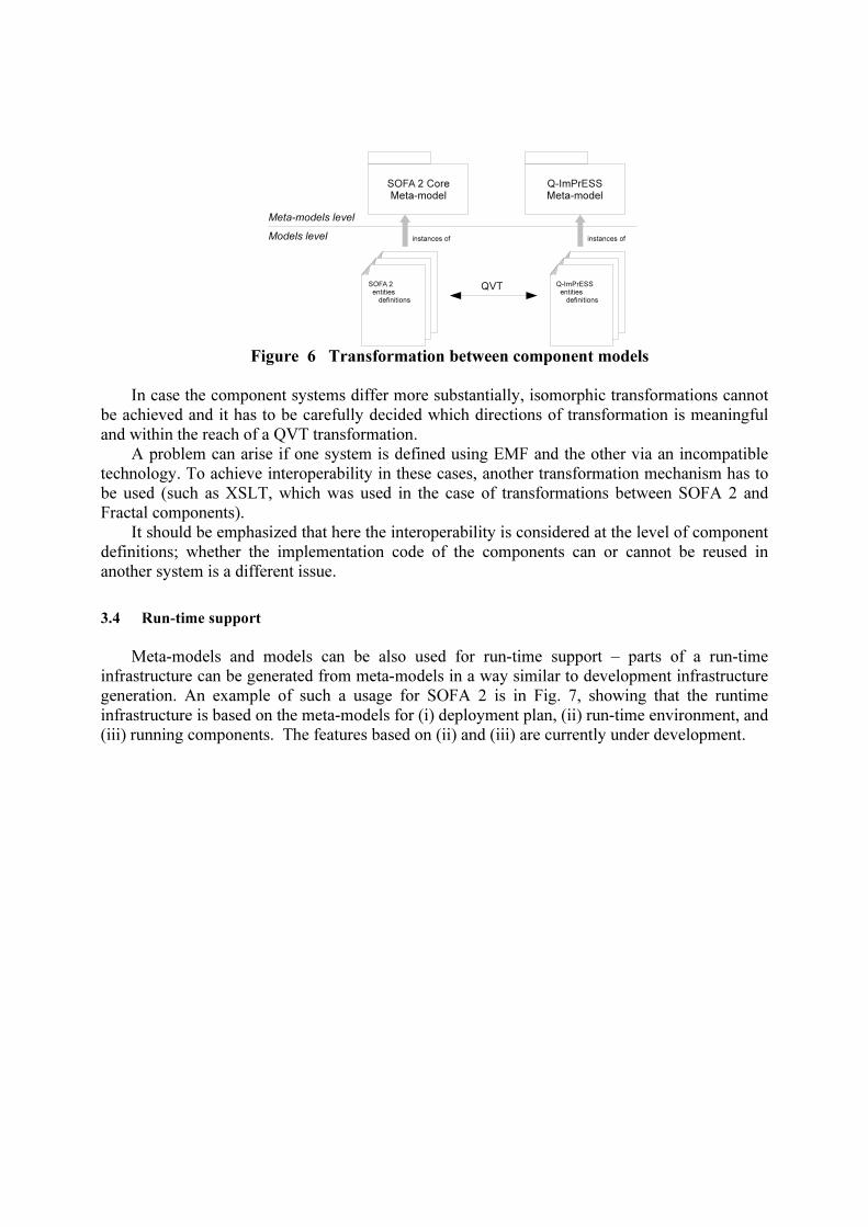
3.3 Transformations among different component models
If two component systems are based on similar abstractions, transformations between them
can be defined via QVT (or a similar transformation language) in order to ensure component
interoperability. An example from the Q-ImPrESS project [32] is shown on Fig. 6 where
instances of the components compliant with the Q-ImPrESS general component model (called
SAM) are converted into SOFA 2 components and vice versa. This way, the tools developed for
SAM components (such as tools for performance prediction) can be applied also to SOFA 2
components.
SOFA 2 Core
Meta-model
Q-ImPrESS
Meta-model
Meta-models level
Models level
SOFA 2
entities
definitions
Q-ImPrESS
entities
definitions
QVT
instances of instances of
Figure 6 Transformation between component models
In case the component systems differ more substantially, isomorphic transformations cannot
be achieved and it has to be carefully decided which directions of transformation is meaningful
and within the reach of a QVT transformation.
A problem can arise if one system is defined using EMF and the other via an incompatible
technology. To achieve interoperability in these cases, another transformation mechanism has to
be used (such as XSLT, which was used in the case of transformations between SOFA 2 and
Fractal components).
It should be emphasized that here the interoperability is considered at the level of component
definitions; whether the implementation code of the components can or cannot be reused in
another system is a different issue.
3.4 Run-time support
Meta-models and models can be also used for run-time support – parts of a run-time
infrastructure can be generated from meta-models in a way similar to development infrastructure
generation. An example of such a usage for SOFA 2 is in Fig. 7, showing that the runtime
infrastructure is based on the meta-models for (i) deployment plan, (ii) run-time environment, and
(iii) running components. The features based on (ii) and (iii) are currently under development.

ADL Meta-model GUI Meta-model
CoreMeta-model
Deployment planMeta-model
Run-timeEnvironmentMeta-model
Run-time related meta-models
Design time related meta-model
prep
aring
depl. p
lan
launching application
report
ing r
esourc
e u
sage
RunningComponentMeta-model
Figure 7 SOFA 2 Meta-models – an overivew
The primary functionality of the deployment plan is to assign instances of components to
particular containers forming a distributed environments (“deployment docks” in SOFA 2),
where they should be executed. From this meta-model, a repository and tree-based editor is
generated by EMF (no visual editor is used, since a tree-based editor is the best option for this
purpose in our experience). Figure 8a shows the key elements of the deployment plan’s meta-
model, while on Figure 8b there is a screen snapshot of the tree-based editor generated from that
metamodel.
a)
DeploymentPlan
InstanceDeploymentDescription
node : String
SubcomponentDeploymentInstance
name : String
PropertyValue
name : Stringvalue : String
1
1
topLevelInstance
1
0..*
subcomponent
1
1instance
1
1propertyValue
b) Figure 8 Deployment plan meta-model and generated tree-based editor

A meta-model of the run time environment formed by distributed deployment docks is easy
to create, since the number of abstractions involved does not exceed ten elements; the meta-
model serves for creating a monitoring tool which provides the current status of the run-time
environment (i.e. of the running deployment docks, number of component instances executed in
each of them, resource consumption, etc.). In fact such a tool, MConsole (Management Console,
Fig. 9), already exists in SOFA 2; currently we are working on replacing its hand-written
implementation by a GMF-based version. The benefit of generating it from the meta-model lies
again in a significant speed up in creating the infrastructure.
Figure 9 MConsole
The meta-model of running components is a little bit more complex. In principle, it covers
running instances of components and their interconnections made of connectors. In particular, it captures the internal building elements of component instances and connectors, i.e. the micro-
components.
With help of this meta-model, a debugger tool is partially created via GMF, i.e., the part of
the tool that visualizes the actual status of component instances via composing the status of their
microcomponents. The debugger reads information from both the model of run-time environment
(to obtain current status of the deployment docks) and the model of running components.
Nevertheless, there still remains an amount of functionality that has to be programmed by hand
(obtaining run-time information about running components, showing the correspondence of
model-level information with the component code, allowing step-by-step execution during
debugging, introspecting and displaying the memory of running components etc.); in any case
even generation of a part of this infrastructure speeds up its development significantly.
4 Evaluation
In essence, in the previous section we have shown that using meta-models makes it possible
to obtain at least part of the design and run-time infrastructures in an automated way. To support
our claims on these benefits of meta-models, we present a comparison of two versions of the
SOFA component system: the original SOFA defined with the help of the concrete syntax of an
ADL, and the newer SOFA 2, defined by a meta-model.

Meta-model Number
of
classes
Number
of
associa-
tions
Develop-
ment time
Tool (partially)
generated
Tool
develop-
ment
time
Hand-written
code/size
Core –
components*
22 25 1 month Repository 1 month Remote access
Core – micro-
components
and control
aspects*
15 22 1 month No visual editor so
far;, currently a
command-line tool
used
Deployment
plan*
11 20 2 weeks Deployment plan
editor – tree-based
generated using EMF
2 week Integration with
other tools,
obtaining status of
run-time
environment
ADL 40** 64** 1 week Command-line based
development tool
3 months Command-line
frontend
GUI 40** 64** 1 week Visual GMF-based
editor
9 months Repository
manager, project
manager, support
for code
compilation,
upload to the
repository
Run-time
env.***
7 10 1 month Runtime viewer and
manager
9 month obtaining status of
running
components
Running
component***
20 25 1 month Debugger 9 months obtaining status of
running
components,
relating model-
level abstractions
shown in the
debugger with
corresponding
code, actual
debugging by step-
by-step execution,
introspecting and
displaying memory
of running
components
Table 1 Basic quantitative characteristics of the SOFA 2 meta-models
As to the original SOFA, its ADL had a CORBA IDL–like structure, enriched by constructs
for describing component types and implementations (architectures). A proprietary concrete
syntax was also used for run-time descriptors (including deployment descriptor). A number of
associations and constraints were specified in a textual, plain English form. The component
* Together used for the repository generation (development time 1 month for adding remote access) ** Mixes elements from all the above meta-models *** Work in progress, estimations only

repository was developed solely in a traditional, non-automated way. As mentioned in [33], the
development of the repository took approximately four person-months and a significant amount
of additional time was spent on debugging. Other approximately two person-months were spent
on developing an ADL compiler. As the SOFA component model evolved, new features were
added (e.g. introduction of software connectors), each of them required a manual modification to
the repository implementation and related tools. Again, each of such modifications took rather
nontrivial amount of time to debug. Stemming from the experience gained during development
and usage of the original SOFA, the design of SOFA 2 was carried out with the help of
EMF/GMF-based meta-modeling. The basic quantitative characteristics of the SOFA 2 meta-
models are in Tab. 1. The gained benefits can be divided to two areas: those related to (1)
generation of both design and run-time infrastructures and (2) component system design itself.
The following subsections discuss both pros and cons of this approach in more detail.
4.1 Pros and cons for infrastructure generation from a meta-model
Here, the gained benefits are threefold:
(a) Component repository. Its development took only one person-month. The repository
interface and implementation was generated in an automated way and just the layer providing
remote access to the repository was written by hand. As mentioned in Section 2.1, by default the
elements of model instances are in the repository stored in files. At the time we started the
development, this was the only option; therefore we developed a thin layer allowing model
storage on an HTTP sever (this layer is not SOFA 2 specific and can be used by any EMF created
repository).
In general, most of the time was spent on designing and tuning the meta-model (Tab. 1),
while the actual repository was generated within few seconds. Since the storage layer is generic,
it was not affected by most of the modification of the meta-model.
On the negative side is the fact that the interface of the generated repository is generic, being,
therefore, less intuitive than a single purpose, ad-hoc written one [33]. On the other hand, the
generic (and thus standardized) interface can be seen as a substantial advantage, since the generic
clients of the repository (e.g. browsers) available elsewhere can be easily reused.
(b) Component development tools. For developing SOFA 2 components, a GMF-based visual
editor proved to be an essential component design tool; also its direct access to generated part of
the component repository is very beneficial. Since the core part of the editor was generated from
the meta-model, its development was five times faster compared to the corresponding tool of the
original SOFA.
As mentioned in Section 3.2, specifying components via ADL is still possible as an auxiliary
option. The ADL definition is also based on a meta-model and there is a QVT transformation
from the ADL format into the format accepted by the repository and vice versa.
On the negative side, there are three issues related to tool generation via EMF/GMF:
(i) The resilience of modifications with respect to the generated tools: In the case the meta-
model is modified, even though the core of the tool can be easily re-generated, its additional
handwritten code has to be updated manually. Naturally, for specific types of meta-model
modification, such as addition of an element, the tool can be used without modification assuming
explicit work with the new element is not essential. For example, in the SOFA 2 context, this was
the case of adding the DeploymentRequirements class (associated with Architecture) via which requirements like the amount of required memory for a particular component can be specified.

After this addition, all the tools still worked as before, given the components’ definitions had no
explicit deployment requirements (some of the tools were enhanced accordingly later on).
(ii) A “heavy-weightiness” of GMF triggering the need of creating a specialized meta-model:
As mentioned in Sect. 3.2, GMF does not permit to associate attributes of more than a single
class (plus its composition classes) with a graphical element. Therefore, a specialized meta-model
for generating a visual editor has to be created and model instances transformed via QVT. In
case of SOFA 2, the transformation is rather simple and the most frequent operation is merging
several entities. Even though the meta-models and QVT transformation (and thus also the GMF-
generated code covering the basic functionality of the visual editor) were prepared relatively
quickly in 1 month, creating a full-fledged, user–friendly version of the editor with all the
functionalities listed in Table 1, took additional 8 months spent on tuning up orchestration of
these functionalities and debugging the corresponding hand written code. Still, the overall time
was significantly shorter then in the case of the original SOFA when just the basic functionality
of the visual editor was considered.
(iii) The need of “views”: Typically, a meta-model is very complex in terms of the number
of elements; for example, many elements are not important for an editor to be generated. As a
remedy, the model has to be simplified via QVT transformations. In case of SOFA 2, such a
solution was used for the concrete syntax ADL (Section 3.2); as an aside, this also reflects the
fact that for such an ADL a number of associations and constraints were to be specified in a
textual, plain English form. In general, nevertheless, EMF-based modeling lacks support for
creating hierarchical abstractions (the only way to partition a meta-model is introduction of
packages). This, however, does not adequately reflect the need for expressing different units of
functionality – they typically involve elements from several packages. Here, introduction of a
concept of view (such as in [34]) would significantly help. Currently, in our experience, such
views have to be introduced manually by dedicated diagrams, which make it hard to maintain
consistency once a change to the meta-model is to be propagated to other depending meta-models
and diagrams.
(c) Models at run-time. The situation is similar as in the case of development tools – the
issues (i) – (iii) have to be addressed. Again, a considerable amount of manual effort has to be
devoted since the models at run-time are dynamic in nature. Even though the visual editor for the
SOFA 2 deployment plan was almost fully generated, the monitoring tool and debugger are
visualization tools in which capturing the dynamicity of models requires a substantial amount of
manual effort (we suppose that necessary time will be again around 9 months for the complete
tool, including 1 month for the meta-models and QVT transformation (Table 1).
4.2 Pros and cons in component system design
The fact that the SOFA 2 component system has been defined via its meta-model has also
several benefits related directly to the component system design – key of them are meta-model
lucidity, steep learning curve, and easy component transformation to other component models.
Below we provide a characterization of these benefits:
(a) Meta-model lucidity. A key advantage is the lucidity of the meta-model itself – it
provides a comprehensive overview of all component system abstractions and their relations.
Also the meta-model efficiently allows seeing the context and judging consequences of a
proposed modification; thereby helping in maintaining the component model consistent when a
modification is needed.
On the contrary, a component system defined with the help of the concrete syntax of an ADL
requires much more to be defined in plain English and thus be more likely ambiguous and error-
prone.
(b) Steep learning curve. The existence of a meta-model significantly reduces the time
required to understand the SOFA 2 component model; usually, to a person familiar with the
commonly used CBD concepts, it was sufficient to only quickly show the meta-model and he/she
immediately understood specific details of SOFA 2. This has proved to be quite important and
beneficial during our participation in the Q-ImPrEES project [32] when sharing details of SOFA
2 with our partners.
(c) Easy component transformation to other component systems. Using QVT-based
transformations, SOFA 2 components were easily converted to comply with another component
system based on similar abstractions (and vice versa). A necessary condition for making this a
reality was that the other component system was also defined via EMF. Such a transformation
has been used in the above mentioned Q-ImPrESS project, where components compliant with the
Q-ImPrESS internal component model were converted into SOFA 2 components – for instance
this has allowed applying the SOFA behavior verification tools to Q-Impress components. We
developed similar transformations - from Fractal to SOFA 2 components - during the CoCoME
contest [8]. However, since Fractal had no EMF meta-model at that time, we had to use XSLT
transformations from Fractal ADL to the SOFA 2 ADL for this purpose.
Overall, compared to the original SOFA defined with the help of concrete syntax of its ADL,
applying the EMF-based meta-model to SOFA 2 has been a big step forward, both in terms of the
clarity of component model specification and implementation easiness of the development and
runtime infrastructures.
Another activity benefiting from the power of meta-model-based component model
definition is the adoption of SOFA 2 into a platform for embedded applications (SOFA HI – High
Integrity [35]), currently under development. Even though it will use a runtime environment
based on the C language, most of the development tools are directly reused, such as the,
repository, SOFA 2 visual editor, and ADL compiler. Roughly speaking, the only parts to be
modified are the tools dealing with the target code generations (e.g. automated provision of
component skeletons).
5 Conclusion
In this paper, we have focused on the issue of how the power of meta-modeling tools can be
employed in an efficient way in the design and implementation of a component system. The
arguments presented here are based on our experience with designing and developing the
component systems SOFA and SOFA 2 and participating in the Q-ImPrESS project.
We have discussed and presented the power of using meta-models in this process. We have
argued that use of meta-models significantly reduces the time necessary to develop a component
repository and the supporting tools in both the design and run-time infrastructures.
Advantageously, since the interfaces of these artifacts generated from meta-models comply with
several standards, it is much easier to provide interoperability among different component
systems and their tools. The issues discussed on the negative side include resilience of
modifications with respect to the generated tools, “heavy-weightiness” of GMF, and lack of
support for “views”. The additional key advantage we have identified (and benefited from) was
related to the design of the component system itself – this is the lucidity of the meta-model and
the steep learning curve allowing to immediately see the context and consequences of any
proposed modification; this very much helps with achieving and maintaining the component
model consistency. This is mostly because the meta-model, in an easy-to-read and
comprehensible manner, defines the associations among the component model abstractions to
such an extent that minimal additional specification in plain English is required in many cases.
Moreover, the expressiveness of the meta-model itself can be further enhanced by applying OCL
constraints.
References 1. CORDET, http://www.pnp-software.com/cordet/ [11 June 2010]
2. Clements P, Northrop L: Software Product Lines: Practices and Patterns, Addison-Wesley Professional,
Aug 2001
3. Crnkovic I, Chaudron M, Larsson S: Component-based Development Process and Component Lifecycle,
Journal of Computing and Information Technology, Vol 13, Num. 4, Nov 2005
4. Magee J, Kramer J: Dynamic Structure in Software Architectures, In proc. of FSE’4, San Francisco, USA,
Oct 1996, DOI: 10.1145/250707.239104
5. Allen R: A Formal Approach to Software Architecture, PhD thesis, School of Computer Science, Carnegie
Mellon University, 1997
6. Garlan D, Monroe RT, Wile D: Acme: Architectural Description of Component-based systems, In
Foundation of Component-based Systems, G. T. Leavens and M. Sitaraman (eds), Cambridge University
Press, 2000
7. Bures T, Decky M, Hnetynka P, Kofron J, Parizek P, Plasil F, Poch T, Sery O, Tuma P: CoCoME in SOFA,
Chapter in The Common Component Modeling Example: Comparing Software Component Models,
Springer-Verlag, LNCS, 2008, DOI: 10.1007/978-3-540-85289-6_15
8. Bulej L, Bures T, Coupaye T, Decky M, Jezek P, Parizek P, Plasil F, Poch T, Rivierre N, Sery O, Tuma P:
CoCoME in Fractal, Chapter in The Common Component Modeling Example: Comparing Software
Component Models, Springer-Verlag, LNCS, Apr 2008, DOI: 10.1007/978-3-540-85289-6_14
9. AADL, http://www.aadl.info/ [11 June 2010]
10. Becker S, Koziolek H, Reussner R: Model-Based Performance Prediction with the Palladio Component
Model, In proc. of WASP 2007, Buenos Aires, Argentina, Feb 2007 DOI: 10.1145/1216993.1217006
11. Bures T, Hnetynka P, Plasil F: SOFA 2.0: Balancing Advanced Features in a Hierarchical Component
Model, In proc. of SERA 2006, Seattle, USA, IEEE CS, Aug 2006, DOI: 10.1109/SERA.2006.62
12. Plasil F, Balek D, Janecek R: SOFA/DCUP: Architecture for Component Trading and Dynamic Updating,
In proc. of ICCDS'98, Annapolis, USA, May 1998, DOI: 10.1109/CDS.1998.675757
13. Brunneton E, Coupaye T, Stefani JB: Recursive and Dynamic Software Composition with Sharing, In proc.
of WCOP’02, Malaga, Spain, Jun 2002
14. Sentilles S, Vulgarakis A, Bures T, Carlson J, Crnkovic I: A Component Model for Control-Intensive
Distributed Embedded Systems, In proc. of CBSE 2008, LNCS 5282, Karlsruhe, Germany, Oct 2008, DOI:
10.1007/978-3-540-87891-9_21
15. Steinberg D, Budinsky F, Paternostro M, Merks E: Eclipse Modeling Framework, 2nd ed., Addison-Wesley
Professional, Dec 2008
16. Hnetynka, P., Plasil, F.: Experience with MOF-Based Meta-modeling of Component-Based Systems, In
Communications in Computer and Information Science (Advances in Software Engineering International
Conference, ASEA 2008, and Its Special Sessions, Sanya, Hainan Island, China, December, 2008. Revised
Selected Papers) , Vol 30, Springer, Nov 2009, DOI: 10.1007/978-3-642-10242-4_4
17. Stahl T, Voelter M: Model-Driven Software Development: Technology, Engineering, Management. Wiley,
May, 2006
18. OMG: MOF 2.0 Core, OMG document formal/06-01-01, Jan 2006
19. Graphical Modeling Framework, http://eclipse.org/gmf [11 June 2010]
20. OMG, MOF QVT, OMG document ptc/07-07-07, Jul 2007
21. Jouault F, Kurtev I: Transforming Models with ATL, In proc. of Satellite Events at the MoDELS 2005
Conference, LNCS 3844, Jan 2006, DOI: 10.1007/11663430_14
22. Jouault F, Kurtev I: On the architectural alignment of ATL and QVT, In proc. of ACM SAC 2006, Dijon,
France, Apr 2006, DOI: 10.1145/1141277.1141561
23. van Ommering R, van der Linden F, Kramer J, Magee J: The Koala Component Model for Consumer
Electronics Software, In IEEE Computer, Vol. 33, No. 3, pp. 78-85, Mar 2000, DOI: 10.1109/2.825699
24. OMG: CORBA Component Model Specification, v 4.0, OMG document formal/06-04-01, Apr 2006
25. OMG: Deployment and Configuration of Component-based Distributed Applications, OMG document
formal/2006-04-02, Apr 2006
26. Seinturier L, Pessemier N, Duchien L, Coupaye T: A Component Model Engineered with Components and
Aspects, In proc. of CBSE'06, Vasteras, Sweden, Jun 2006, DOI: 10.1007/11783565_10
27. Fassino JP, Stefani JB, Lawall J, Muller G: Think: A Software Framework for Component-based Operating
System Kernels, In Proc. of the 2002 USENIX Annual Tech. Conf., Monterey, USA, Jun 2002
28. Fractal website, http://fractal.ow2.org/ [11 June 2010]
29. OSOA: Service Component Architecture – Assembly Model Specification, 2007,
http://www.osoa.org/display/Main/Service+Component+Architecture+Specifications [11 June 2010]
30. Perez J, Ali N, Carsi JA, Ramos I: Designing Software Architectures with an Aspect-Oriented Architecture
Description Language, In proc. of CBSE’06, Vasteras, Sweden, Jun 2006, DOI: 10.1007/11783565_9
31. Mencl V, Bures T: Microcomponent-Based Component Controllers: A Foundation for Component Aspects,
In Proc. APSEC 2005, Taipei, Taiwan, IEEE CS, Dec 2005, DOI: 10.1109/APSEC.2005.78
32. Q-ImPrESS, http://www.q-impress.eu/ [11 June 2010]
33. Hnetynka P, Pise M: Hand-written vs. MOF-based Metadata Repositories: The SOFA Experience, In proc.
of ECBS 2004, Brno, Czech Republic, IEEE CS, May 2004, DOI: 10.1109/ECBS.2004.1316716
34. Atkinson C: Orthographic Software Modelling: A Novel Approach to View-Based Software Engineering, In
proc. of ECMFA 2010, LNCS, Paris, France, Jun 2010, DOI: 10.1007/978-3-642-13595-8_1
35. Prochazka M, Ward R, Tuma P, Hnetynka P, Adamek J: A Component-Oriented Framework for Spacecraft
On-Board Software, In proc. of DASIA 2008, DAta Systems In Aerospace, Palma de Mallorca, European
Space Agency Report Nr. SP-665, May 2008
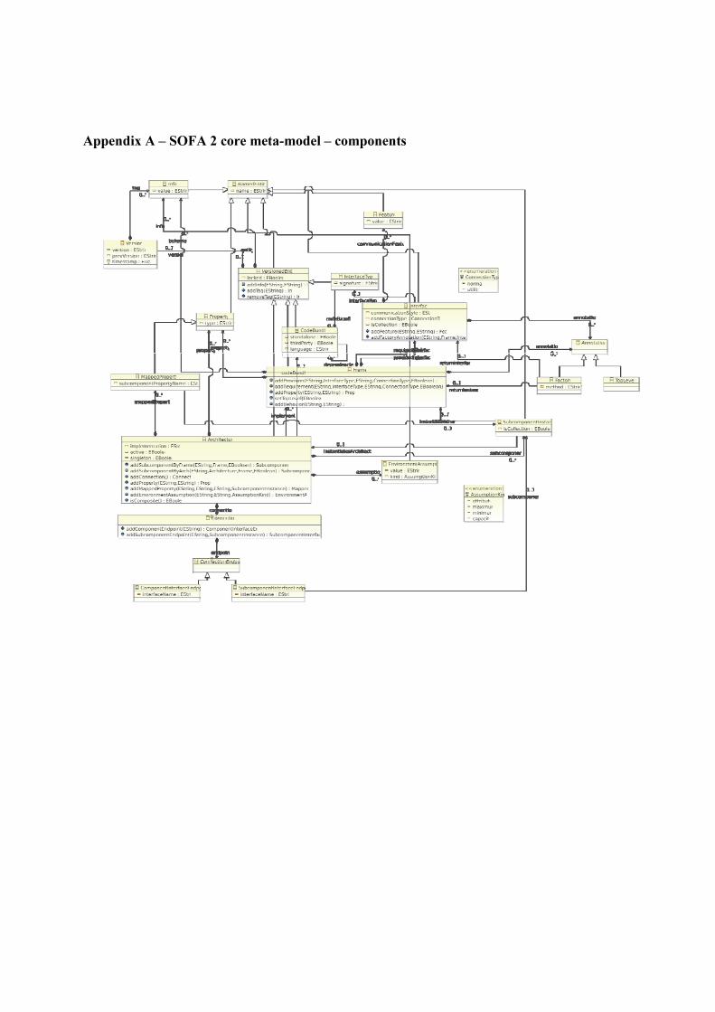
Appendix A – SOFA 2 core meta-model – components

Appendix B – SOFA 2 core meta-model – micro-components