using rapid prototyped parts to quickly create,...
TRANSCRIPT

Inside This Issue
1 Introduction and description of problem 2 Using SolidWorks to design 3D models for rapid prototyping3 3D Printing & Assembling prototyping parts: Prototyped parts used to create silicon mold tool Prototyped parts used to create silicon insert fixture4 Testing viability with surrogate prototyped parts5 Results
Using Rapid Prototyped parts to quickly create, waterproof, pressure capable, over-molded Electrical Connectors

Figure 1
Introduction and description of problemIn this issue, we will explore using FDM (Fused Deposition Modeling) 3D printing to quickly rapid prototype parts that will be used to create permanent, waterproof, pressure capable, over-molded Electrical Connectors.
In this case study, the customer’s desire was to over-mold a 37 pin connector to make the connector water-proof and pressure capable. Due to project time constraints, the connector needed to be over-molded and ready for testing in three days. Due to this rigorous schedule, traditional manufacturing techniques would not suffice and rapid prototyping was the only option.
Due to the limited supply and cost per connector, the customer requested that Coho Designs offer a solution to demonstrate the likelihood that the potting material, used in the over-mold, would penetrate the wire assembly and seal the connector from water ingress-this includes adhering to the wire jacket and

elimination of air-bubbles. Coho Designs suggested 3D printing a surrogate prototype of the connector to practice pouring potting compound and for part dissection-to prove whether or not air bubbles were present.
This issue will demonstrate the techniques employed by Coho Designs to accomplish this task
Using SolidWorks to design 3D models for rapid prototypingUsing SolidWorks, Coho Designs started this project by reverse engineering the electrical connector. Without the OEM drawing for the connector assembly Coho Designs needed to reverse engineer the connector assembly. Having this component, duplicated accurately in 3D, was paramount to the success of the project (reference Figure 2)
Figure 2
Having duplicated the connector in SolidWorks it was necessary to start the design of the silicon mold. Silicon molds are required because the potting compound, encapsulating the connector, would permanently adhere to the ABS plastic FDM parts. Geometry constraints determined that the silicon molds needed to be manufactured from a two part construction, split vertically down the center, to facilitate pouring of the viscous potting compound and bleeding of trapped air (reference Figure 3).

Figure 3
Figure 4
After designing the silicon molds a tool must be designed to manufacture the silicon molds. This silicon mold tool will be rapid prototyped via FDM. To save time and reduce cost the silicon mold tool was designed in such a way that the same parts could be used to make the Left-hand mold and turned “inside out” to make the Right-hand mold. In doing so, only the internal plug needed to be
Potting encapsulate pour slot
Aft vent hole to eliminate trapped air

3D printed as an additional component (left hand & right hand)(reference Figure 5).
Figure 5
Brass, press-fit inserts were installed into the rapid prototyped parts to increase the longevity of the FDM printed tool (reference the Figure 6).
Figure 6
At this point all that was left to design was the silicon insert fixture. This rapid prototyped assembly will rigidly hold the silicon molds stationary relative to each other as well as provide a slope to assist in pouring of the encapsulate material. This part too was designed with brass press fit inserts to increase tool longevity and reuse (reference Figure 7 and 8).
LH Internal Plug
Silicon Mold Tool
Brass, Press-Fit Inserts
RH Internal Plug

Figure 7
Figure 8
3D Printing & Assembling prototyping parts:

After completing the design of the components in SolidWorks each part necessary to build the silicon mold tool and silicon insert fixture were exported and saved as “.stl” files. Most CAD packages today are capable of exporting this format. STL files are necessary for the 3D printing of FDM parts on Dimension printers. Employing the use of Coho Designs in-house 3D printers the above mentioned parts were 3D printed overnight and ready for assembly the next morning (reference Figure 9)
Figure 9

Prototyped parts used to create silicon mold tool
Figure 10
Installation of brass press-fit inserts (reference Figure 11)
Figure 11

Completed Silicon Mold Tool Assembly (reference Figure 12).
Figure 12
Manufacturing silicon molds from FDM silicon mold tool (reference Figure 13).
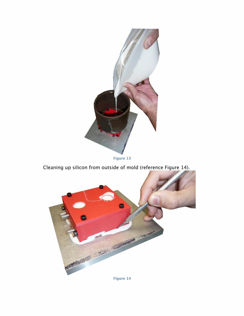
Figure 13
Cleaning up silicon from outside of mold (reference Figure 14).
Figure 14

After removing the silicon mold from silicon mold tool some trimming operations are necessary to make the edges crisp (reference Figure 15).
Figure 15
Prototyped parts used to create silicon insert fixtureSilicon insert fixtures prior to brass, press-insert installation (reference Figure 16).
Perform trimming operations to parting line features

Figure 16
Silicon insert fixture LH & RH assembled with silicon mold inserts installed (reference Figure 17).
Figure 17
Testing viability with surrogate prototyped partsPrior to encapsulating the real connectors surrogate FDM connectors were 3D printed, from the reverse engineered connector (reference Figure 2) and

assembled just like its counterpart metal connector. This surrogate prototype connector, with wires installed, was carefully inserted into the mold and potted just as if it were a real metal connector (Figure 18).
Figure 18
After encapsulating the surrogate connector it was removed from the fixture (reference Figure 19)
Figure 19
and trimmed to final shape (reference Figure 20).

Figure 20
The surrogate FDM connector is ready to be cut in half on a band saw and inspected for air-bubbles (reference Figure 21).
Figure 21

ResultsPrinting surrogate FDM connectors allowed Coho Designs to quickly and cost effectively validate the silicon molds as a viable option to over-mold the electrical connectors without having to discard or waste a real, metal connector. Moreover, employing the use of rapid prototyping allowed Coho Designs to step up to the challenge and meet the customer’s rigid time schedule and exceed their expectations (reference Figure 22)
Figure 22