using stream surfaces for blade design
DESCRIPTION
energyTRANSCRIPT
Using stream surfaces for blade designby Perry L. Miller
IV, James H. Oliver, David P.
Miller, and Daniel L. Tweedt
A new, interactive program offers parameters that are familiar to the designer of turbomachinery blades while it produces a precise and portable NURBS surface model
A wide variety of machines with rotating components incorporate blades for imparting energy to, or extracting it from, various fluid streams. The complex interaction between the fluid mechanics and the blade geometry is of fundamental importance in blade design.
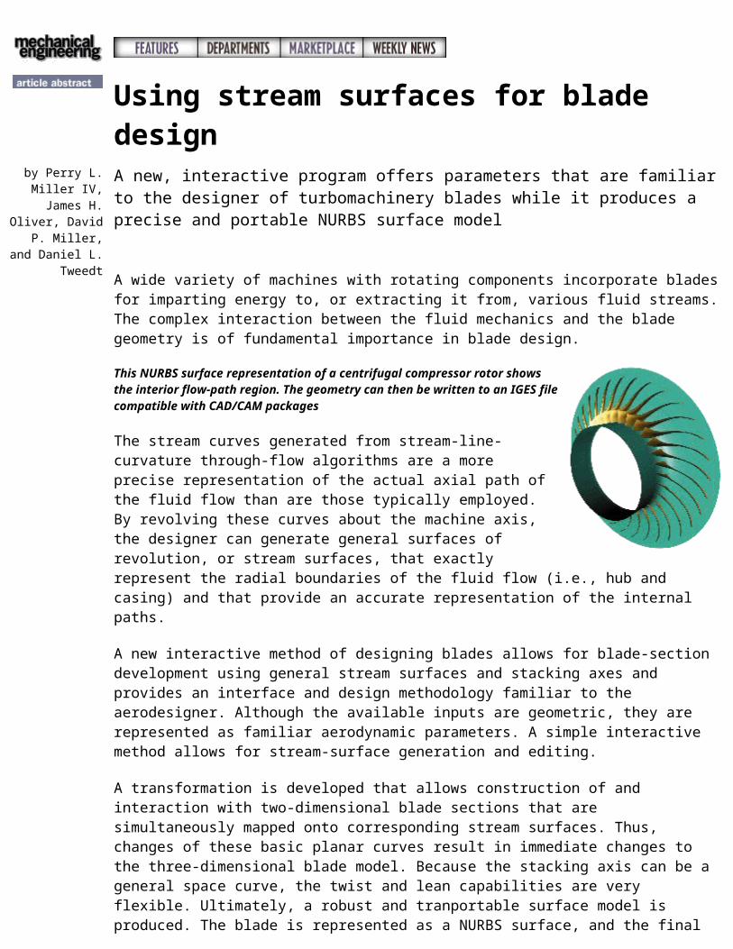
This NURBS surface representation of a centrifugal compressor rotor shows the interior flow-path region. The geometry can then be written to an IGES file compatible with CAD/CAM packages
The stream curves generated from stream-line-curvature through-flow algorithms are a more precise representation of the actual axial path of the fluid flow than are those typically employed. By revolving these curves about the machine axis, the designer can generate general surfaces of revolution, or stream surfaces, that exactly represent the radial boundaries of the fluid flow (i.e., hub and casing) and that provide an accurate representation of the internal paths.
A new interactive method of designing blades allows for blade-section development using general stream surfaces and stacking axes and provides an interface and design methodology familiar to the aerodesigner. Although the available inputs are geometric, they are represented as familiar aerodynamic parameters. A simple interactive method allows for stream-surface generation and editing.
A transformation is developed that allows construction of and interaction with two-dimensional blade sections that are simultaneously mapped onto corresponding stream surfaces. Thus, changes of these basic planar curves result in immediate changes to the three-dimensional blade model. Because the stacking axis can be a general space curve, the twist and lean capabilities are very flexible. Ultimately, a robust and tranportable surface model is produced. The blade is represented as a NURBS surface, and the final output is a standard IGES file. The blade-surface geometry can then be analyzed by existing computational-fluid-dynamics packages.
The new design methodology BladeCAD’s user interface is supported by OSF/Motif, and Silicon Graphics Open Inventor is used for graphic display and interaction. BladeCAD is not limited to axial turbomachinery components. Radial flow turbomachinery components such as impellers are designed with the same procedures. The software is general enough to design all types of turbomachinery blades.
The above was adapted from an article by Perry L. Miller IV, a graduate student at Iowa State University in Ames, James H. Oliver, an associate professor of mechanical engineering at Iowa State University, and David P. Miller and Daniel L. Tweedt, aerospace engineers at the NASA Lewis Research Center in Cleveland. The full text may be found in the March 1997 issue of Mechanical Engineering magazine. © 1997 ASME International.©
© 1997 by The American Society of Mechanical Engineers