using the ac motor control pwm etpu functions...using the ac motor control pwm etpu functions, rev....
TRANSCRIPT
Freescale SemiconductorApplication Note
AN2969Rev. 1, 10/2005
Table of Contents1 Introduction..........................................................12 Function Overview...............................................13 Function Description............................................24 C Level API for Function....................................165 Example Use of Function ..................................266 Summary and Conclusions ...............................28
Using the AC Motor Control PWM eTPU FunctionsCovers the MCF523x, MPC5500, and all eTPU-equipped Devices by: Milan Brejl
System Application Engineer, Roznov Czech System CenterMichal PrincSystem Application Engineer, Roznov Czech System Center
1 IntroductionThe generation of PWM signals for AC motor-control applications with eTPU is provided by two eTPU functions:
• PWM - Master for AC motors (PWMMAC)• PWM - Full range (PWMF)
The PWMMAC and PWMF eTPU functions are located in the AC motor control eTPU function set (set4). This eTPU application note is intended to provide simple C interface routines to the PWMMAC and PWMF eTPU functions. The routines are targeted at the MCF523x and MPC5500 families of devices, but they could be easily used with any device that has an eTPU.
2 Function OverviewThe PWMMAC and PWMF functions enable the eTPU to generate PWM signals for driving a motor. The PWM master (PWMMAC) function synchronizes and updates
© Freescale Semiconductor, Inc., 2005. All rights reserved.
Function Description
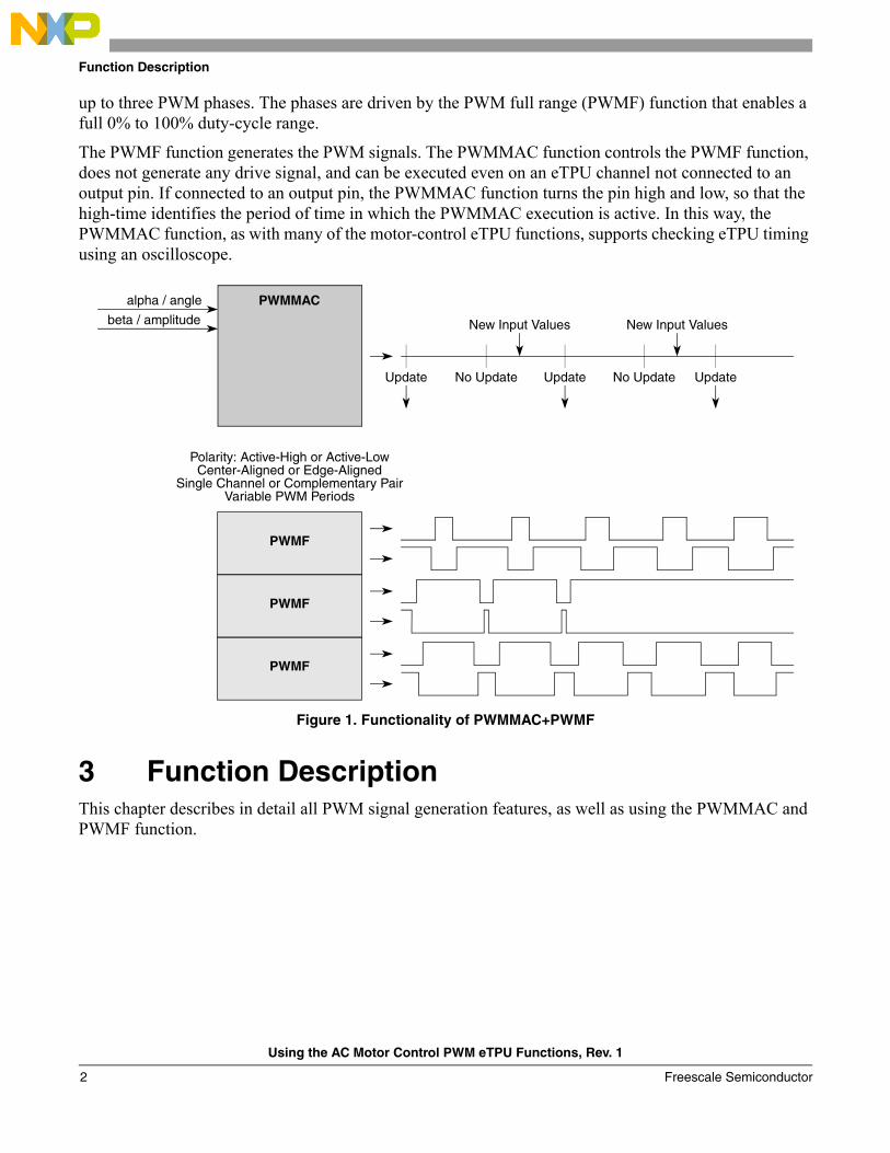
up to three PWM phases. The phases are driven by the PWM full range (PWMF) function that enables a full 0% to 100% duty-cycle range.
The PWMF function generates the PWM signals. The PWMMAC function controls the PWMF function, does not generate any drive signal, and can be executed even on an eTPU channel not connected to an output pin. If connected to an output pin, the PWMMAC function turns the pin high and low, so that the high-time identifies the period of time in which the PWMMAC execution is active. In this way, the PWMMAC function, as with many of the motor-control eTPU functions, supports checking eTPU timing using an oscilloscope.
Figure 1. Functionality of PWMMAC+PWMF
3 Function DescriptionThis chapter describes in detail all PWM signal generation features, as well as using the PWMMAC and PWMF function.
PWMF
PWMF
PWMF
Polarity: Active-High or Active-Low
PWMMAC
Center-Aligned or Edge-AlignedSingle Channel or Complementary Pair
Variable PWM Periods
Update UpdateNo Update No Update Update
New Input Values New Input Valuesbeta / amplitude
alpha / angle
Using the AC Motor Control PWM eTPU Functions, Rev. 1
Freescale Semiconductor2
Function Description
3.1 ModulationsThe PWMMAC function transforms input parameters into phase duty-cycles by modulation. The following modulations are provided by the PWMMAC function:
• Unsigned Voltage (VOLTAGE_UNSIGNED) - The input parameter is an applied motor voltage in the range (0,1). The voltage range (0,1) corresponds to the duty-cycle range (0%, 100%). Zero voltage corresponds to a 0% duty-cycle. All phases are controlled by the same duty-cycle, optionally negated (see Section 3.2.4, “Negate Duty: Transform Duty-cycle Value to its Opposite”).
• Signed Voltage (VOLTAGE_SIGNED) - The input parameter is an applied motor voltage in the range (-1,1). The voltage range (-1,1) corresponds to the duty-cycle range (0%, 100%). Zero voltage corresponds to a 50% duty-cycle. All phases are controlled by the same duty-cycle, optional negated (see Section 3.2.4, “Negate Duty: Transform Duty-cycle Value to its Opposite”).
• No Modulation (NO) - No input parameters are transformed into phase duty-cycles. The phase duty-cycles must be provided.
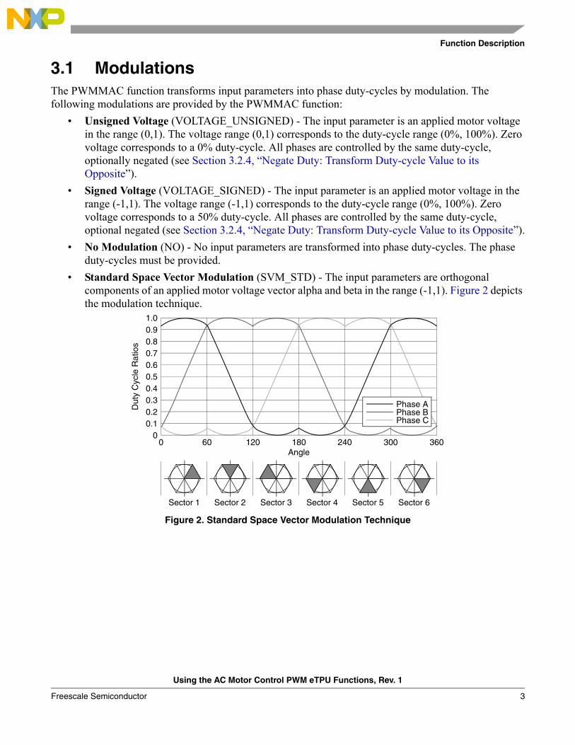
• Standard Space Vector Modulation (SVM_STD) - The input parameters are orthogonal components of an applied motor voltage vector alpha and beta in the range (-1,1). Figure 2 depicts the modulation technique.
Figure 2. Standard Space Vector Modulation Technique
1.00.90.80.70.60.50.40.30.20.1
00 60 120 180 240 300 360
Phase APhase BPhase C
Angle
Sector 1 Sector 2 Sector 3 Sector 4 Sector 5 Sector 6
Dut
y C
ycle
Rat
ios
Using the AC Motor Control PWM eTPU Functions, Rev. 1
Freescale Semiconductor 3
Function Description
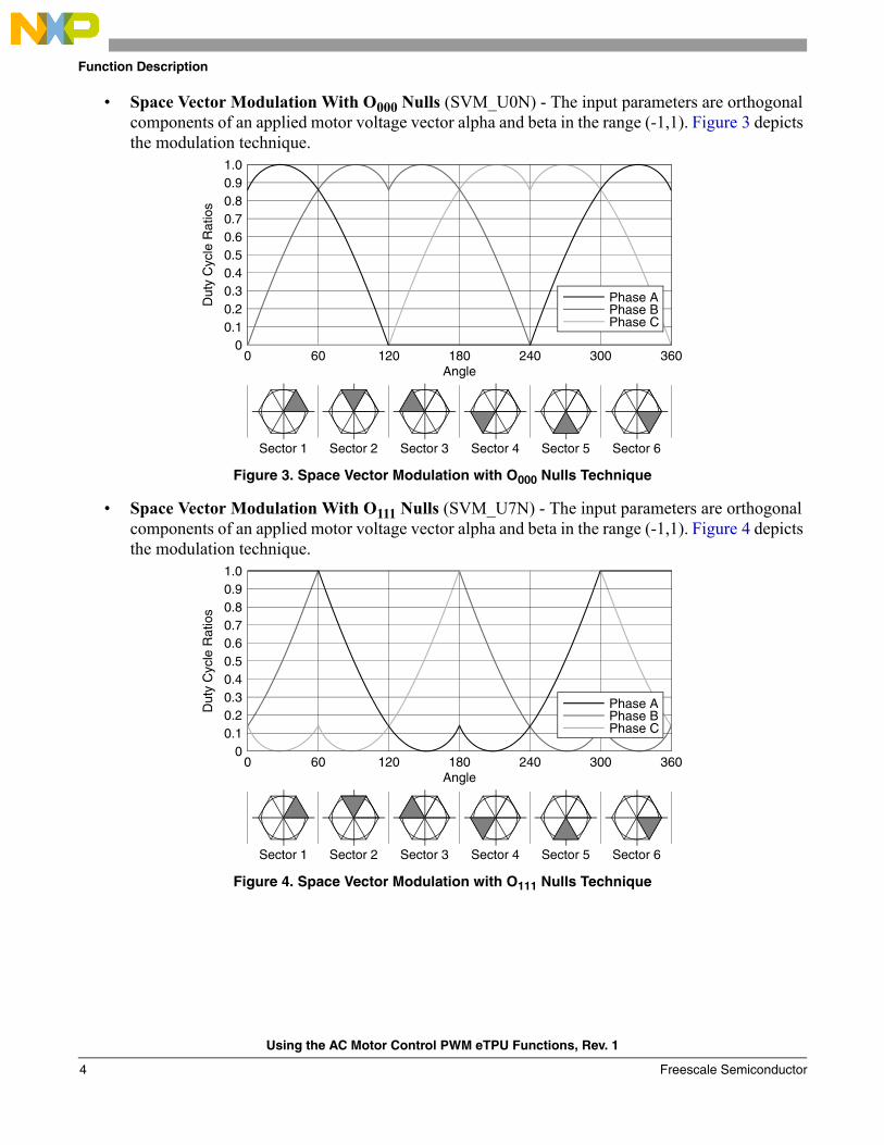
• Space Vector Modulation With O000 Nulls (SVM_U0N) - The input parameters are orthogonal components of an applied motor voltage vector alpha and beta in the range (-1,1). Figure 3 depicts the modulation technique.
Figure 3. Space Vector Modulation with O000 Nulls Technique
• Space Vector Modulation With O111 Nulls (SVM_U7N) - The input parameters are orthogonal components of an applied motor voltage vector alpha and beta in the range (-1,1). Figure 4 depicts the modulation technique.
Figure 4. Space Vector Modulation with O111 Nulls Technique
1.00.90.80.70.60.50.40.30.20.1
00 60 120 180 240 300 360
Angle
Sector 1 Sector 2 Sector 3 Sector 4 Sector 5 Sector 6
Dut
y C
ycle
Rat
ios
Phase APhase BPhase C
1.00.90.80.70.60.50.40.30.20.1
00 60 120 180 240 300 360
Angle
Sector 1 Sector 2 Sector 3 Sector 4 Sector 5 Sector 6
Dut
y C
ycle
Rat
ios
Phase APhase BPhase C
Using the AC Motor Control PWM eTPU Functions, Rev. 1
Freescale Semiconductor4
Function Description
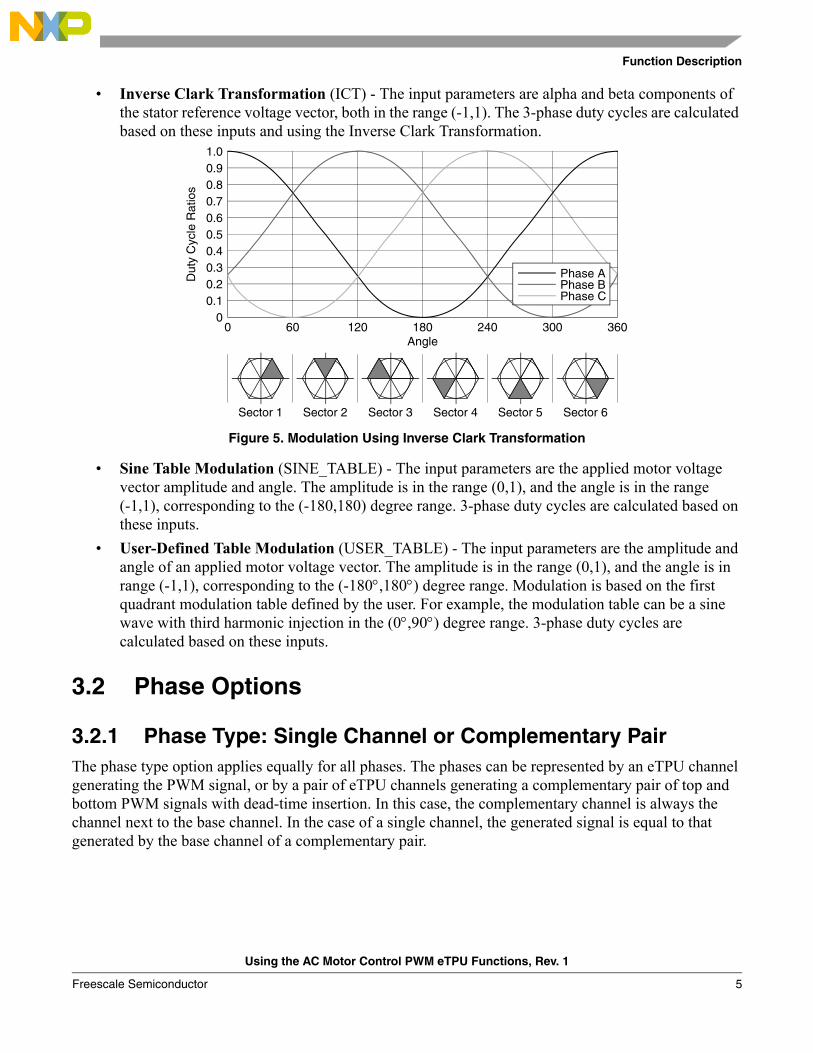
• Inverse Clark Transformation (ICT) - The input parameters are alpha and beta components of the stator reference voltage vector, both in the range (-1,1). The 3-phase duty cycles are calculated based on these inputs and using the Inverse Clark Transformation.
Figure 5. Modulation Using Inverse Clark Transformation
• Sine Table Modulation (SINE_TABLE) - The input parameters are the applied motor voltage vector amplitude and angle. The amplitude is in the range (0,1), and the angle is in the range (-1,1), corresponding to the (-180,180) degree range. 3-phase duty cycles are calculated based on these inputs.
• User-Defined Table Modulation (USER_TABLE) - The input parameters are the amplitude and angle of an applied motor voltage vector. The amplitude is in the range (0,1), and the angle is in range (-1,1), corresponding to the (-180°,180°) degree range. Modulation is based on the first quadrant modulation table defined by the user. For example, the modulation table can be a sine wave with third harmonic injection in the (0°,90°) degree range. 3-phase duty cycles are calculated based on these inputs.
3.2 Phase Options
3.2.1 Phase Type: Single Channel or Complementary PairThe phase type option applies equally for all phases. The phases can be represented by an eTPU channel generating the PWM signal, or by a pair of eTPU channels generating a complementary pair of top and bottom PWM signals with dead-time insertion. In this case, the complementary channel is always the channel next to the base channel. In the case of a single channel, the generated signal is equal to that generated by the base channel of a complementary pair.
1.00.90.80.70.60.50.40.30.20.1
00 60 120 180 240 300 360
Angle
Sector 1 Sector 2 Sector 3 Sector 4 Sector 5 Sector 6
Dut
y C
ycle
Rat
ios
Phase APhase BPhase C
Using the AC Motor Control PWM eTPU Functions, Rev. 1
Freescale Semiconductor 5
Function Description
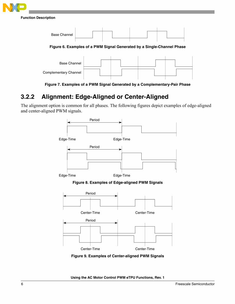
Figure 6. Examples of a PWM Signal Generated by a Single-Channel Phase
Figure 7. Examples of a PWM Signal Generated by a Complementary-Pair Phase
3.2.2 Alignment: Edge-Aligned or Center-AlignedThe alignment option is common for all phases. The following figures depict examples of edge-aligned and center-aligned PWM signals.
Figure 8. Examples of Edge-aligned PWM Signals
Figure 9. Examples of Center-aligned PWM Signals
Base Channel
Base Channel
Complementary Channel
Period
Edge-Time Edge-Time
Period
Edge-Time Edge-Time
Period
Center-Time Center-Time
Period
Center-Time Center-Time
Using the AC Motor Control PWM eTPU Functions, Rev. 1
Freescale Semiconductor6
Function Description
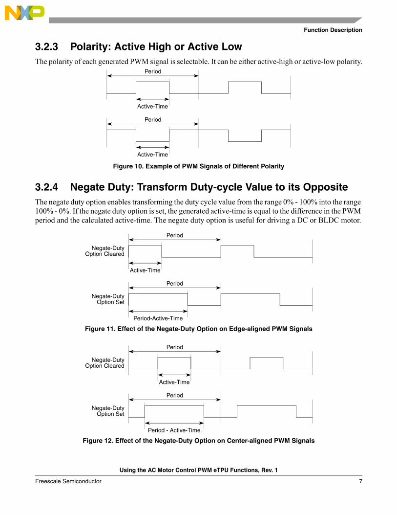
3.2.3 Polarity: Active High or Active LowThe polarity of each generated PWM signal is selectable. It can be either active-high or active-low polarity.
Figure 10. Example of PWM Signals of Different Polarity
3.2.4 Negate Duty: Transform Duty-cycle Value to its OppositeThe negate duty option enables transforming the duty cycle value from the range 0% - 100% into the range 100% - 0%. If the negate duty option is set, the generated active-time is equal to the difference in the PWM period and the calculated active-time. The negate duty option is useful for driving a DC or BLDC motor.
Figure 11. Effect of the Negate-Duty Option on Edge-aligned PWM Signals
Figure 12. Effect of the Negate-Duty Option on Center-aligned PWM Signals
Period
Active-Time
Period
Active-Time
Period
Active-Time
Period
Period-Active-Time
Negate-DutyOption Cleared
Negate-DutyOption Set
Period
Period
Period - Active-Time
Negate-DutyOption Cleared
Negate-DutyOption Set
Active-Time
Using the AC Motor Control PWM eTPU Functions, Rev. 1
Freescale Semiconductor 7
Function Description
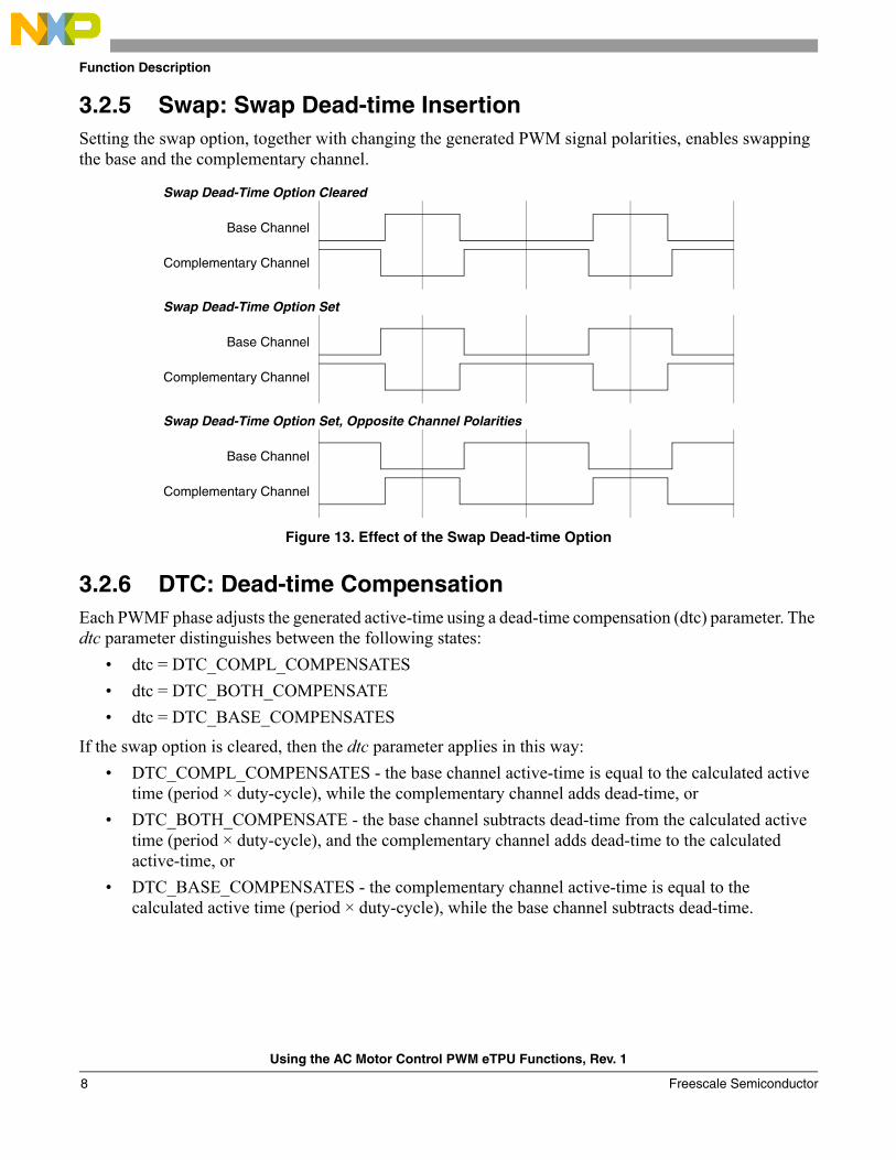
3.2.5 Swap: Swap Dead-time InsertionSetting the swap option, together with changing the generated PWM signal polarities, enables swapping the base and the complementary channel.
Figure 13. Effect of the Swap Dead-time Option
3.2.6 DTC: Dead-time CompensationEach PWMF phase adjusts the generated active-time using a dead-time compensation (dtc) parameter. The dtc parameter distinguishes between the following states:
• dtc = DTC_COMPL_COMPENSATES• dtc = DTC_BOTH_COMPENSATE• dtc = DTC_BASE_COMPENSATES
If the swap option is cleared, then the dtc parameter applies in this way:• DTC_COMPL_COMPENSATES - the base channel active-time is equal to the calculated active
time (period × duty-cycle), while the complementary channel adds dead-time, or• DTC_BOTH_COMPENSATE - the base channel subtracts dead-time from the calculated active
time (period × duty-cycle), and the complementary channel adds dead-time to the calculated active-time, or
• DTC_BASE_COMPENSATES - the complementary channel active-time is equal to the calculated active time (period × duty-cycle), while the base channel subtracts dead-time.
Base Channel
Complementary Channel
Swap Dead-Time Option Cleared
Base Channel
Complementary Channel
Swap Dead-Time Option Set
Base Channel
Complementary Channel
Swap Dead-Time Option Set, Opposite Channel Polarities
Using the AC Motor Control PWM eTPU Functions, Rev. 1
Freescale Semiconductor8
Function Description
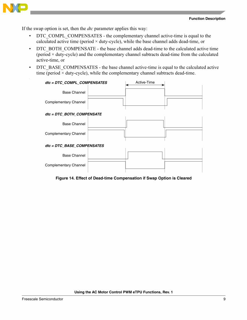
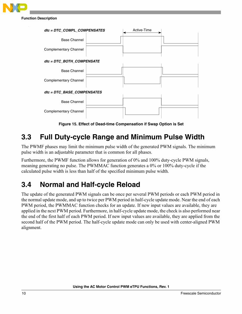
If the swap option is set, then the dtc parameter applies this way:• DTC_COMPL_COMPENSATES - the complementary channel active-time is equal to the
calculated active time (period × duty-cycle), while the base channel adds dead-time, or• DTC_BOTH_COMPENSATE - the base channel adds dead-time to the calculated active time
(period × duty-cycle) and the complementary channel subtracts dead-time from the calculated active-time, or
• DTC_BASE_COMPENSATES - the base channel active-time is equal to the calculated active time (period × duty-cycle), while the complementary channel subtracts dead-time.
•
Figure 14. Effect of Dead-time Compensation if Swap Option is Cleared
Base Channel
Complementary Channel
dtc = DTC_COMPL_COMPENSATES
Base Channel
Complementary Channel
dtc = DTC_BOTH_COMPENSATE
Base Channel
Complementary Channel
dtc = DTC_BASE_COMPENSATES
Active-Time
Using the AC Motor Control PWM eTPU Functions, Rev. 1
Freescale Semiconductor 9
Function Description
•
Figure 15. Effect of Dead-time Compensation if Swap Option is Set
3.3 Full Duty-cycle Range and Minimum Pulse WidthThe PWMF phases may limit the minimum pulse width of the generated PWM signals. The minimum pulse width is an adjustable parameter that is common for all phases.
Furthermore, the PWMF function allows for generation of 0% and 100% duty-cycle PWM signals, meaning generating no pulse. The PWMMAC function generates a 0% or 100% duty-cycle if the calculated pulse width is less than half of the specified minimum pulse width.
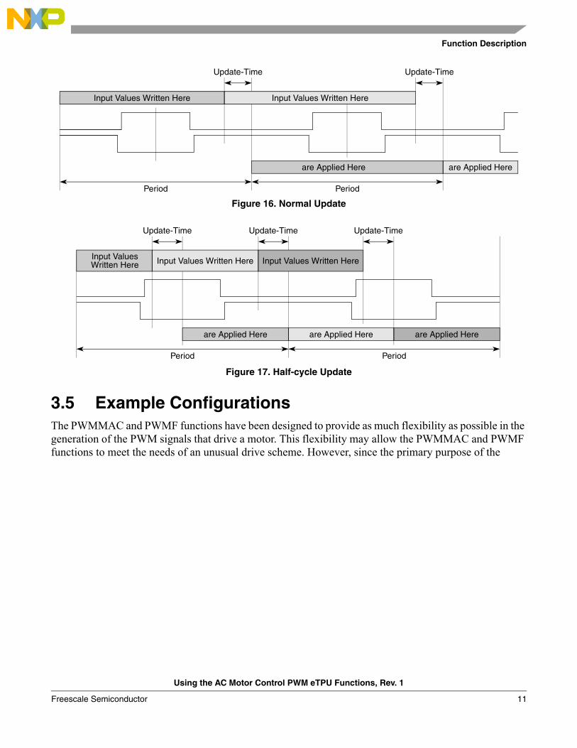
3.4 Normal and Half-cycle ReloadThe update of the generated PWM signals can be once per several PWM periods or each PWM period in the normal update mode, and up to twice per PWM period in half-cycle update mode. Near the end of each PWM period, the PWMMAC function checks for an update. If new input values are available, they are applied in the next PWM period. Furthermore, in half-cycle update mode, the check is also performed near the end of the first half of each PWM period. If new input values are available, they are applied from the second half of the PWM period. The half-cycle update mode can only be used with center-aligned PWM alignment.
Base Channel
Complementary Channel
dtc = DTC_COMPL_COMPENSATES
Base Channel
Complementary Channel
dtc = DTC_BOTH_COMPENSATE
Base Channel
Complementary Channel
dtc = DTC_BASE_COMPENSATES
Active-Time
Using the AC Motor Control PWM eTPU Functions, Rev. 1
Freescale Semiconductor10
Function Description
Figure 16. Normal Update
Figure 17. Half-cycle Update
3.5 Example ConfigurationsThe PWMMAC and PWMF functions have been designed to provide as much flexibility as possible in the generation of the PWM signals that drive a motor. This flexibility may allow the PWMMAC and PWMF functions to meet the needs of an unusual drive scheme. However, since the primary purpose of the
Input Values Written Here Input Values Written Here
Update-Time Update-Time
are Applied Here
Period Period
are Applied Here
Input Values Written Here Input Values Written Here
Update-Time Update-Time
are Applied Here
Period Period
Input ValuesWritten Here
Update-Time
are Applied Hereare Applied Here
Using the AC Motor Control PWM eTPU Functions, Rev. 1
Freescale Semiconductor 11
Function Description
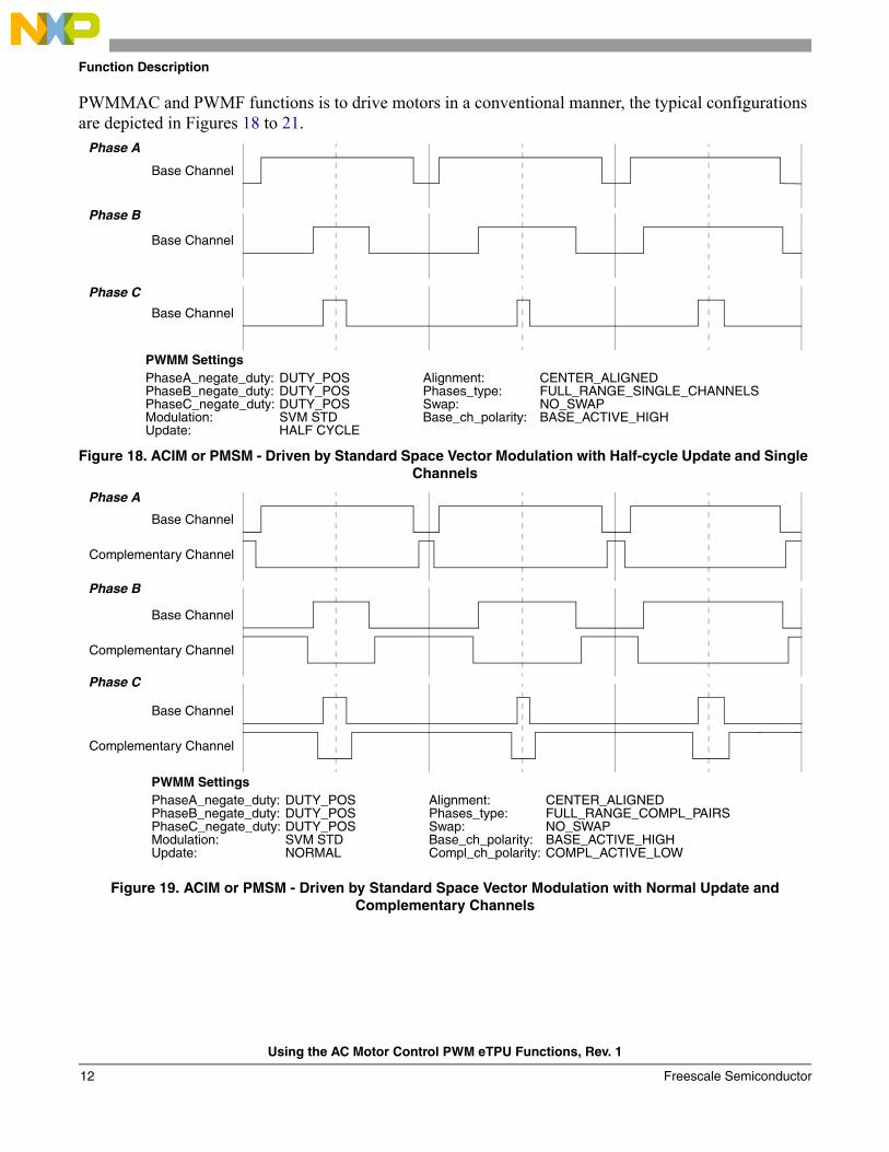
PWMMAC and PWMF functions is to drive motors in a conventional manner, the typical configurations are depicted in Figures 18 to 21.
Figure 18. ACIM or PMSM - Driven by Standard Space Vector Modulation with Half-cycle Update and Single Channels
Figure 19. ACIM or PMSM - Driven by Standard Space Vector Modulation with Normal Update and Complementary Channels
Base Channel
Phase A
Base Channel
Phase B
PhaseA_negate_duty:PhaseB_negate_duty:PhaseC_negate_duty:Modulation:
DUTY_POSDUTY_POSDUTY_POSSVM STD
Alignment:Phases_type:Swap:Base_ch_polarity:
CENTER_ALIGNEDFULL_RANGE_SINGLE_CHANNELSNO_SWAPBASE_ACTIVE_HIGH
PWMM Settings
Base Channel
Phase C
Update: HALF CYCLE
Base Channel
Complementary Channel
Phase A
Base Channel
Complementary Channel
Phase B
PhaseA_negate_duty:PhaseB_negate_duty:PhaseC_negate_duty:Modulation:
DUTY_POSDUTY_POSDUTY_POSSVM STD
Alignment:Phases_type:Swap:Base_ch_polarity:
CENTER_ALIGNEDFULL_RANGE_COMPL_PAIRSNO_SWAPBASE_ACTIVE_HIGH
Compl_ch_polarity: COMPL_ACTIVE_LOW
PWMM Settings
Base Channel
Complementary Channel
Phase C
Update: NORMAL
Using the AC Motor Control PWM eTPU Functions, Rev. 1
Freescale Semiconductor12
Function Description
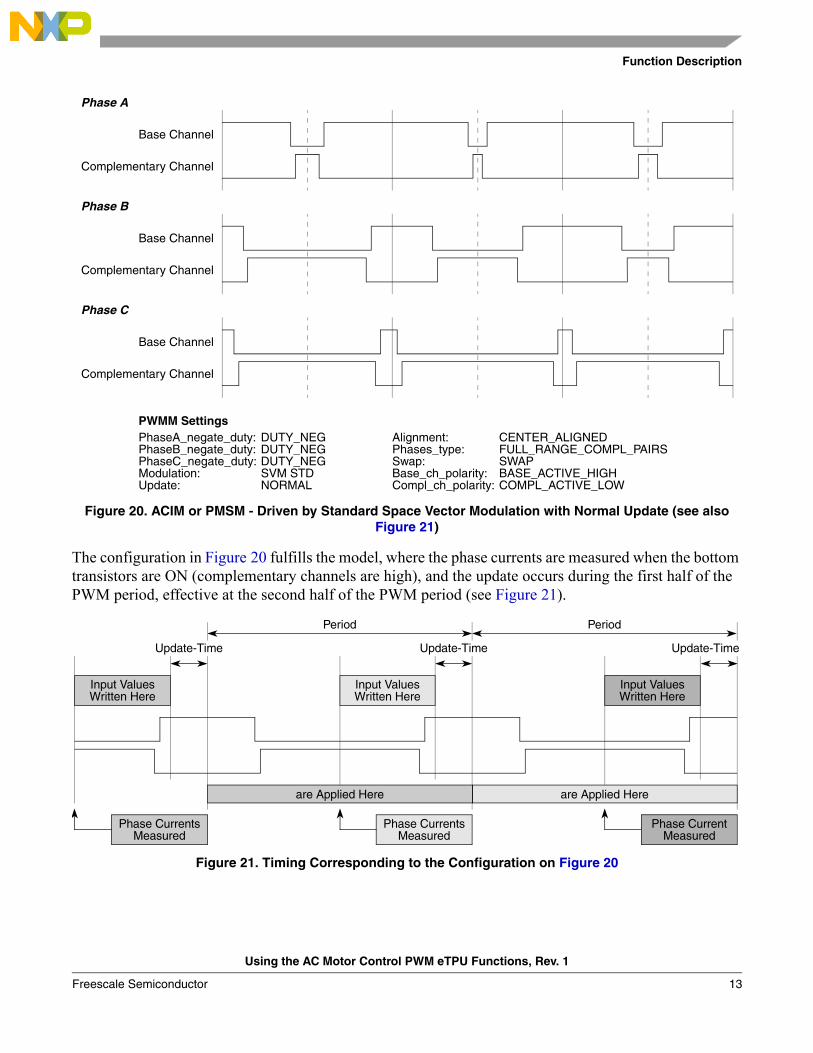
Figure 20. ACIM or PMSM - Driven by Standard Space Vector Modulation with Normal Update (see also Figure 21)
The configuration in Figure 20 fulfills the model, where the phase currents are measured when the bottom transistors are ON (complementary channels are high), and the update occurs during the first half of the PWM period, effective at the second half of the PWM period (see Figure 21).
Figure 21. Timing Corresponding to the Configuration on Figure 20
Base Channel
Complementary Channel
Phase A
Base Channel
Complementary Channel
Phase B
PhaseA_negate_duty:PhaseB_negate_duty:PhaseC_negate_duty:Modulation:
DUTY_NEGDUTY_NEGDUTY_NEGSVM STD
Alignment:Phases_type:Swap:Base_ch_polarity:
CENTER_ALIGNEDFULL_RANGE_COMPL_PAIRSSWAPBASE_ACTIVE_HIGH
Compl_ch_polarity: COMPL_ACTIVE_LOW
PWMM Settings
Base Channel
Complementary Channel
Phase C
Update: NORMAL
are Applied Here
Period
Input ValuesWritten Here
Update-Time
are Applied Here
Update-Time
Input ValuesWritten Here
Input ValuesWritten Here
Update-Time
Period
Phase CurrentsMeasured
Phase CurrentsMeasured
Phase CurrentMeasured
Using the AC Motor Control PWM eTPU Functions, Rev. 1
Freescale Semiconductor 13
Function Description
3.6 InterruptsThe PWMMAC function periodically generates an interrupt service request to the CPU. The generation of interrupt service requests depends on the type of update: one interrupt per PWM period is generated in the normal update mode, two interrupts per PWM period are generated in the half-cycle update mode.
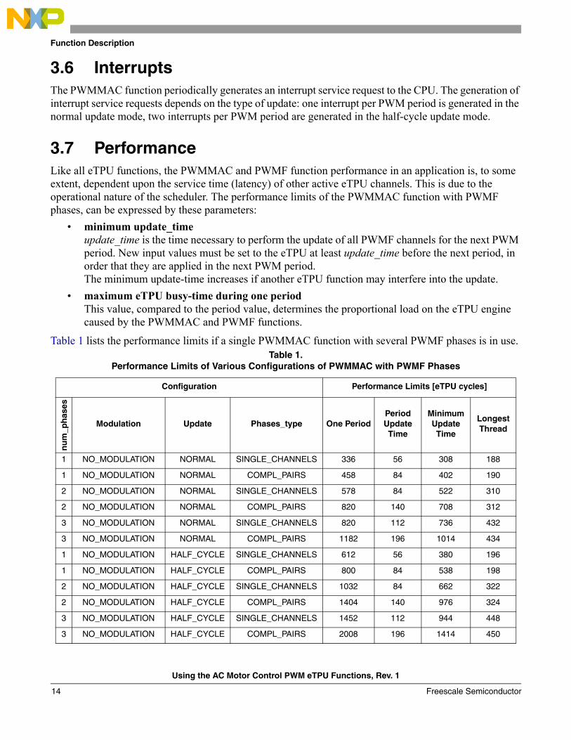
3.7 PerformanceLike all eTPU functions, the PWMMAC and PWMF function performance in an application is, to some extent, dependent upon the service time (latency) of other active eTPU channels. This is due to the operational nature of the scheduler. The performance limits of the PWMMAC function with PWMF phases, can be expressed by these parameters:
• minimum update_timeupdate_time is the time necessary to perform the update of all PWMF channels for the next PWM period. New input values must be set to the eTPU at least update_time before the next period, in order that they are applied in the next PWM period.The minimum update-time increases if another eTPU function may interfere into the update.
• maximum eTPU busy-time during one periodThis value, compared to the period value, determines the proportional load on the eTPU engine caused by the PWMMAC and PWMF functions.
Table 1 lists the performance limits if a single PWMMAC function with several PWMF phases is in use. Table 1.
Performance Limits of Various Configurations of PWMMAC with PWMF Phases
Configuration Performance Limits [eTPU cycles]
nu
m_p
has
es
Modulation Update Phases_type One PeriodPeriod Update Time
Minimum Update Time
Longest Thread
1 NO_MODULATION NORMAL SINGLE_CHANNELS 336 56 308 188
1 NO_MODULATION NORMAL COMPL_PAIRS 458 84 402 190
2 NO_MODULATION NORMAL SINGLE_CHANNELS 578 84 522 310
2 NO_MODULATION NORMAL COMPL_PAIRS 820 140 708 312
3 NO_MODULATION NORMAL SINGLE_CHANNELS 820 112 736 432
3 NO_MODULATION NORMAL COMPL_PAIRS 1182 196 1014 434
1 NO_MODULATION HALF_CYCLE SINGLE_CHANNELS 612 56 380 196
1 NO_MODULATION HALF_CYCLE COMPL_PAIRS 800 84 538 198
2 NO_MODULATION HALF_CYCLE SINGLE_CHANNELS 1032 84 662 322
2 NO_MODULATION HALF_CYCLE COMPL_PAIRS 1404 140 976 324
3 NO_MODULATION HALF_CYCLE SINGLE_CHANNELS 1452 112 944 448
3 NO_MODULATION HALF_CYCLE COMPL_PAIRS 2008 196 1414 450
Using the AC Motor Control PWM eTPU Functions, Rev. 1
Freescale Semiconductor14
Function Description
1 VOLTAGE_SIGNED / VOLTAGE_UNSIGNED
NORMAL SINGLE_CHANNELS 356 76 328 188
1 VOLTAGE_SIGNED / VOLTAGE_UNSIGNED
NORMAL COMPL_PAIRS 478 104 422 190
2 VOLTAGE_SIGNED / VOLTAGE_UNSIGNED
NORMAL SINGLE_CHANNELS 598 104 542 310
2 VOLTAGE_SIGNED / VOLTAGE_UNSIGNED
NORMAL COMPL_PAIRS 840 160 728 312
3 VOLTAGE_SIGNED / VOLTAGE_UNSIGNED
NORMAL SINGLE_CHANNELS 840 132 756 432
3 VOLTAGE_SIGNED / VOLTAGE_UNSIGNED
NORMAL COMPL_PAIRS 1202 216 1034 434
1 VOLTAGE_SIGNED / VOLTAGE_UNSIGNED
HALF_CYCLE SINGLE_CHANNELS 652 76 400 196
1 VOLTAGE_SIGNED / VOLTAGE_UNSIGNED
HALF_CYCLE COMPL_PAIRS 840 104 558 198
2 VOLTAGE_SIGNED / VOLTAGE_UNSIGNED
HALF_CYCLE SINGLE_CHANNELS 1072 104 682 322
2 VOLTAGE_SIGNED / VOLTAGE_UNSIGNED
HALF_CYCLE COMPL_PAIRS 1444 160 996 324
3 VOLTAGE_SIGNED / VOLTAGE_UNSIGNED
HALF_CYCLE SINGLE_CHANNELS 1492 132 964 448
3 VOLTAGE_SIGNED / VOLTAGE_UNSIGNED
HALF_CYCLE COMPL_PAIRS 2048 216 1434 450
3 SVM_STD /SVM_U0N / SVM_U7N
NORMAL SINGLE_CHANNELS 1002 294 918 432
3 SVM_STD /SVM_U0N / SVM_U7N
NORMAL COMPL_PAIRS 1364 378 1196 434
3 SVM_STD /SVM_U0N / SVM_U7N
HALF_CYCLE SINGLE_CHANNELS 1816 294 1126 448
3 SVM_STD /SVM_U0N / SVM_U7N
HALF_CYCLE SINGLE_CHANNELS 2372 378 1596 450
3 SVM_ICT NORMAL SINGLE_CHANNELS 980 272 896 432
3 SVM_ICT NORMAL COMPL_PAIRS 1342 356 1174 434
3 SVM_ICT HALF_CYCLE SINGLE_CHANNELS 1772 272 1104 448
3 SVM_ICT HALF_CYCLE COMPL_PAIRS 2328 356 1574 450
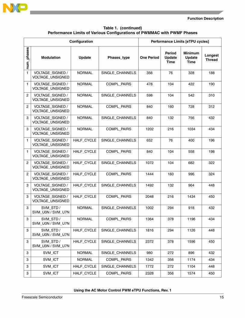
Table 1. (continued)Performance Limits of Various Configurations of PWMMAC with PWMF Phases
Configuration Performance Limits [eTPU cycles]
nu
m_p
has
es
Modulation Update Phases_type One PeriodPeriod Update Time
Minimum Update Time
Longest Thread
Using the AC Motor Control PWM eTPU Functions, Rev. 1
Freescale Semiconductor 15
C Level API for Function
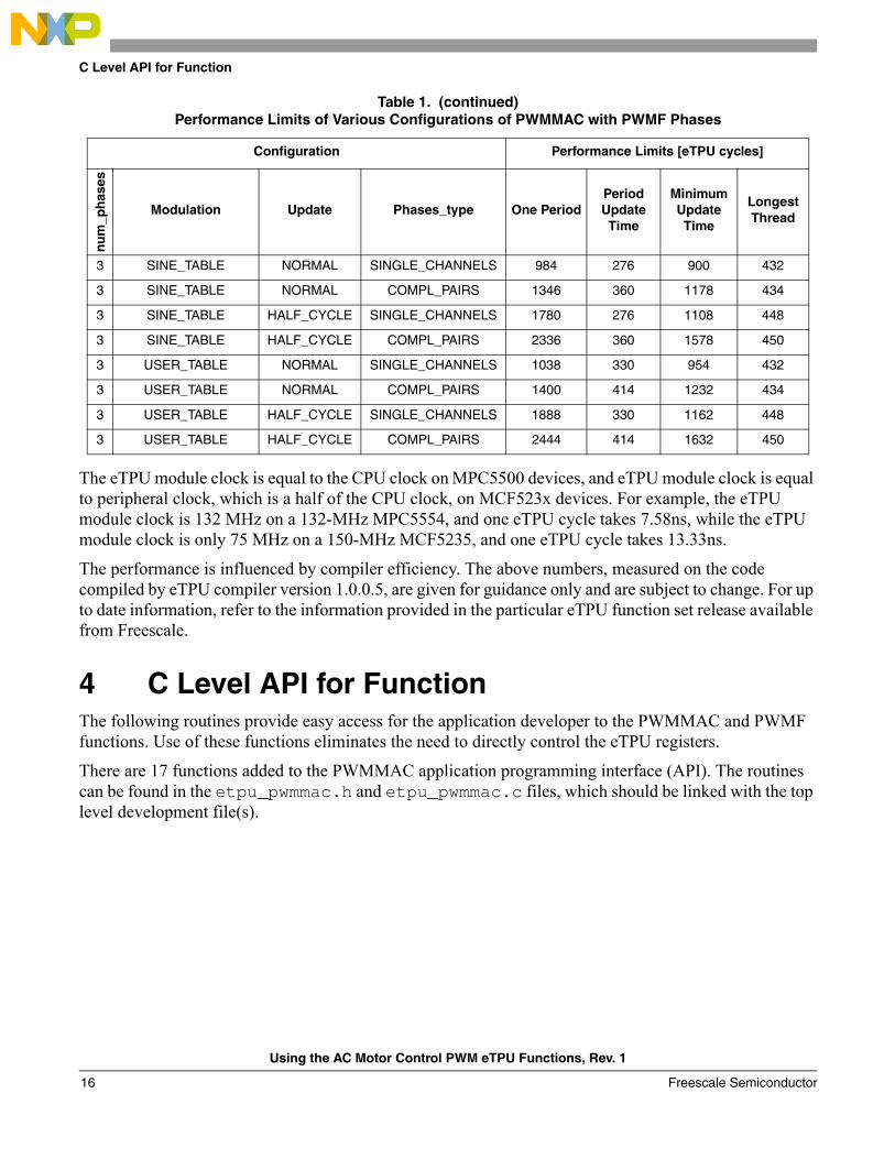
The eTPU module clock is equal to the CPU clock on MPC5500 devices, and eTPU module clock is equal to peripheral clock, which is a half of the CPU clock, on MCF523x devices. For example, the eTPU module clock is 132 MHz on a 132-MHz MPC5554, and one eTPU cycle takes 7.58ns, while the eTPU module clock is only 75 MHz on a 150-MHz MCF5235, and one eTPU cycle takes 13.33ns.
The performance is influenced by compiler efficiency. The above numbers, measured on the code compiled by eTPU compiler version 1.0.0.5, are given for guidance only and are subject to change. For up to date information, refer to the information provided in the particular eTPU function set release available from Freescale.
4 C Level API for FunctionThe following routines provide easy access for the application developer to the PWMMAC and PWMF functions. Use of these functions eliminates the need to directly control the eTPU registers.
There are 17 functions added to the PWMMAC application programming interface (API). The routines can be found in the etpu_pwmmac.h and etpu_pwmmac.c files, which should be linked with the top level development file(s).
3 SINE_TABLE NORMAL SINGLE_CHANNELS 984 276 900 432
3 SINE_TABLE NORMAL COMPL_PAIRS 1346 360 1178 434
3 SINE_TABLE HALF_CYCLE SINGLE_CHANNELS 1780 276 1108 448
3 SINE_TABLE HALF_CYCLE COMPL_PAIRS 2336 360 1578 450
3 USER_TABLE NORMAL SINGLE_CHANNELS 1038 330 954 432
3 USER_TABLE NORMAL COMPL_PAIRS 1400 414 1232 434
3 USER_TABLE HALF_CYCLE SINGLE_CHANNELS 1888 330 1162 448
3 USER_TABLE HALF_CYCLE COMPL_PAIRS 2444 414 1632 450
Table 1. (continued)Performance Limits of Various Configurations of PWMMAC with PWMF Phases
Configuration Performance Limits [eTPU cycles]
nu
m_p
has
es
Modulation Update Phases_type One PeriodPeriod Update Time
Minimum Update Time
Longest Thread
Using the AC Motor Control PWM eTPU Functions, Rev. 1
Freescale Semiconductor16
C Level API for Function
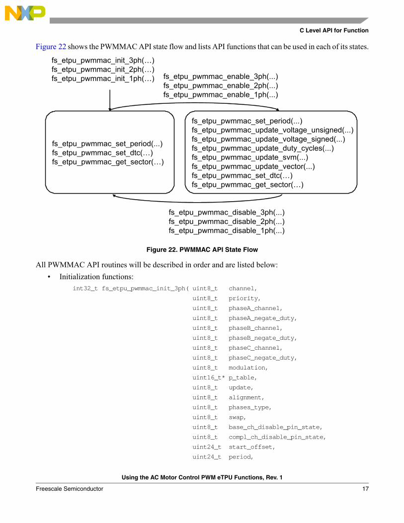
Figure 22 shows the PWMMAC API state flow and lists API functions that can be used in each of its states.
Figure 22. PWMMAC API State Flow
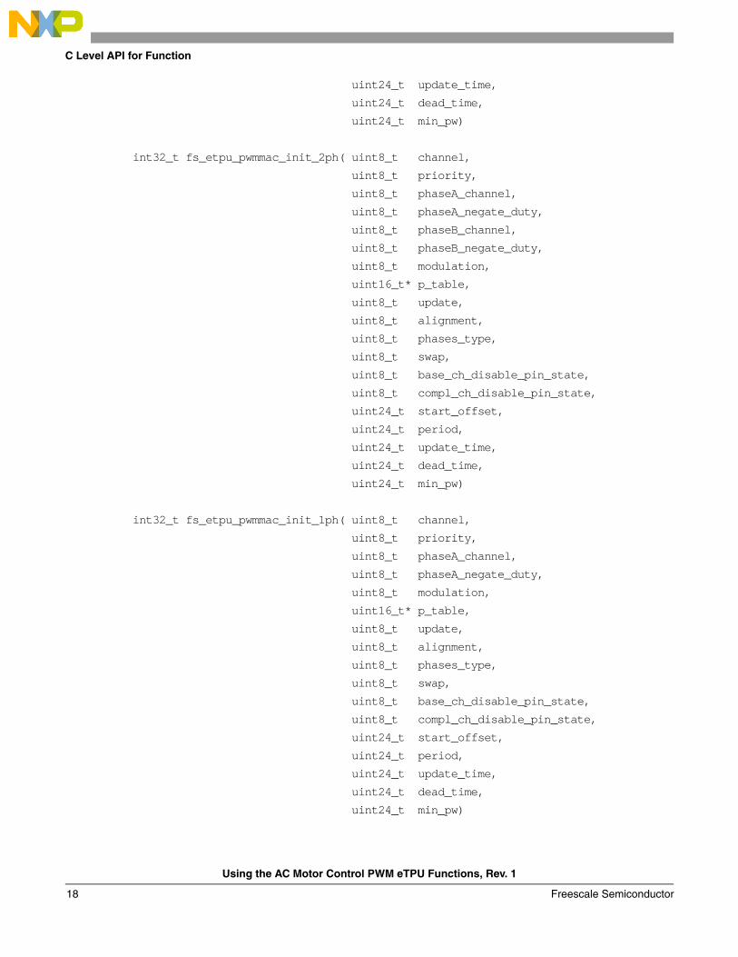
All PWMMAC API routines will be described in order and are listed below:• Initialization functions:
int32_t fs_etpu_pwmmac_init_3ph( uint8_t channel,
uint8_t priority,
uint8_t phaseA_channel,
uint8_t phaseA_negate_duty,
uint8_t phaseB_channel,
uint8_t phaseB_negate_duty,
uint8_t phaseC_channel,
uint8_t phaseC_negate_duty,
uint8_t modulation,
uint16_t* p_table,
uint8_t update,
uint8_t alignment,
uint8_t phases_type,
uint8_t swap,
uint8_t base_ch_disable_pin_state,
uint8_t compl_ch_disable_pin_state,
uint24_t start_offset,
uint24_t period,
fs_etpu_pwmmac_init_3ph(…)fs_etpu_pwmmac_init_2ph(…)fs_etpu_pwmmac_init_1ph(…)
fs_etpu_pwmmac_set_period(...)fs_etpu_pwmmac_set_dtc(…)fs_etpu_pwmmac_get_sector(…)
fs_etpu_pwmmac_disable_3ph(...)fs_etpu_pwmmac_disable_2ph(...)fs_etpu_pwmmac_disable_1ph(...)
fs_etpu_pwmmac_enable_3ph(...)fs_etpu_pwmmac_enable_2ph(...)fs_etpu_pwmmac_enable_1ph(...)
fs_etpu_pwmmac_set_period(...)fs_etpu_pwmmac_update_voltage_unsigned(...)fs_etpu_pwmmac_update_voltage_signed(...)fs_etpu_pwmmac_update_duty_cycles(...)fs_etpu_pwmmac_update_svm(...)fs_etpu_pwmmac_update_vector(...)fs_etpu_pwmmac_set_dtc(…)fs_etpu_pwmmac_get_sector(…)
Using the AC Motor Control PWM eTPU Functions, Rev. 1
Freescale Semiconductor 17
C Level API for Function
uint24_t update_time,
uint24_t dead_time,
uint24_t min_pw)
int32_t fs_etpu_pwmmac_init_2ph( uint8_t channel,
uint8_t priority,
uint8_t phaseA_channel,
uint8_t phaseA_negate_duty,
uint8_t phaseB_channel,
uint8_t phaseB_negate_duty,
uint8_t modulation,
uint16_t* p_table,
uint8_t update,
uint8_t alignment,
uint8_t phases_type,
uint8_t swap,
uint8_t base_ch_disable_pin_state,
uint8_t compl_ch_disable_pin_state,
uint24_t start_offset,
uint24_t period,
uint24_t update_time,
uint24_t dead_time,
uint24_t min_pw)
int32_t fs_etpu_pwmmac_init_1ph( uint8_t channel,
uint8_t priority,
uint8_t phaseA_channel,
uint8_t phaseA_negate_duty,
uint8_t modulation,
uint16_t* p_table,
uint8_t update,
uint8_t alignment,
uint8_t phases_type,
uint8_t swap,
uint8_t base_ch_disable_pin_state,
uint8_t compl_ch_disable_pin_state,
uint24_t start_offset,
uint24_t period,
uint24_t update_time,
uint24_t dead_time,
uint24_t min_pw)
Using the AC Motor Control PWM eTPU Functions, Rev. 1
Freescale Semiconductor18
C Level API for Function
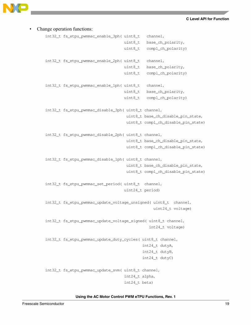
• Change operation functions:int32_t fs_etpu_pwmmac_enable_3ph( uint8_t channel,
uint8_t base_ch_polarity,
uint8_t compl_ch_polarity)
int32_t fs_etpu_pwmmac_enable_2ph( uint8_t channel,
uint8_t base_ch_polarity,
uint8_t compl_ch_polarity)
int32_t fs_etpu_pwmmac_enable_1ph( uint8_t channel,
uint8_t base_ch_polarity,
uint8_t compl_ch_polarity)
int32_t fs_etpu_pwmmac_disable_3ph( uint8_t channel,
uint8_t base_ch_disable_pin_state,
uint8_t compl_ch_disable_pin_state)
int32_t fs_etpu_pwmmac_disable_2ph( uint8_t channel,
uint8_t base_ch_disable_pin_state,
uint8_t compl_ch_disable_pin_state)
int32_t fs_etpu_pwmmac_disable_1ph( uint8_t channel,
uint8_t base_ch_disable_pin_state,
uint8_t compl_ch_disable_pin_state)
int32_t fs_etpu_pwmmac_set_period( uint8_t channel,
uint24_t period)
int32_t fs_etpu_pwmmac_update_voltage_unsigned( uint8_t channel,
uint24_t voltage)
int32_t fs_etpu_pwmmac_update_voltage_signed( uint8_t channel,
int24_t voltage)
int32_t fs_etpu_pwmmac_update_duty_cycles( uint8_t channel,
int24_t dutyA,
int24_t dutyB,
int24_t dutyC)
int32_t fs_etpu_pwmmac_update_svm( uint8_t channel,
int24_t alpha,
int24_t beta)
Using the AC Motor Control PWM eTPU Functions, Rev. 1
Freescale Semiconductor 19
C Level API for Function
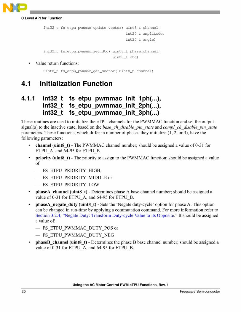
int32_t fs_etpu_pwmmac_update_vector( uint8_t channel,
int24_t amplitude,
int24_t angle)
int32_t fs_etpu_pwmmac_set_dtc( uint8_t phase_channel,
uint8_t dtc)
• Value return functions:uint8_t fs_etpu_pwmmac_get_sector( uint8_t channel)
4.1 Initialization Function
4.1.1 int32_t fs_etpu_pwmmac_init_1ph(...), int32_t fs_etpu_pwmmac_init_2ph(...), int32_t fs_etpu_pwmmac_init_3ph(...)
These routines are used to initialize the eTPU channels for the PWMMAC function and set the output signal(s) to the inactive state, based on the base_ch_disable_pin_state and compl_ch_disable_pin_state parameters. These functions, which differ in number of phases they initialize (1, 2, or 3), have the following parameters:
• channel (uint8_t) - The PWMMAC channel number; should be assigned a value of 0-31 for ETPU_A, and 64-95 for ETPU_B.
• priority (uint8_t) - The priority to assign to the PWMMAC function; should be assigned a value of:— FS_ETPU_PRIORITY_HIGH,— FS_ETPU_PRIORITY_MIDDLE or— FS_ETPU_PRIORITY_LOW
• phaseA_channel (uint8_t) - Determines phase A base channel number; should be assigned a value of 0-31 for ETPU_A, and 64-95 for ETPU_B.
• phaseA_negate_duty (uint8_t) - Sets the ‘Negate duty-cycle’ option for phase A. This option can be changed in run-time by applying a commutation command. For more information refer to Section 3.2.4, “Negate Duty: Transform Duty-cycle Value to its Opposite.” It should be assigned a value of:— FS_ETPU_PWMMAC_DUTY_POS or— FS_ETPU_PWMMAC_DUTY_NEG
• phaseB_channel (uint8_t) - Determines the phase B base channel number; should be assigned a value of 0-31 for ETPU_A, and 64-95 for ETPU_B.
Using the AC Motor Control PWM eTPU Functions, Rev. 1
Freescale Semiconductor20
C Level API for Function
• phaseB_negate_duty (uint8_t) - Sets the ‘Negate duty-cycle’ option for phase B. This option can be changed in run-time by applying a commutation command. For more information refer to Section 3.2.4, “Negate Duty: Transform Duty-cycle Value to its Opposite.” It should be assigned a value of:— FS_ETPU_PWMMAC_DUTY_POS or— FS_ETPU_PWMMAC_DUTY_NEG
• phaseC_channel (uint8_t) - Determines phase C base channel number; should be assigned a value of 0-31 for ETPU_A, and 64-95 for ETPU_B.
• phaseC_negate_duty (uint8_t) - Sets the ‘Negate duty-cycle’ option for phase C. This option can be changed in run-time by applying a commutation command. For more information refer to Section 3.2.4, “Negate Duty: Transform Duty-cycle Value to its Opposite.” It should be assigned a value of:— FS_ETPU_PWMMAC_DUTY_POS or— FS_ETPU_PWMMAC_DUTY_NEG
• modulation (uint8_t) - Determines the type of modulation. For more information refer to Section 3.1, “Modulations.” It should be assigned a value of:— FS_ETPU_PWMMAC_MOD_NO or— FS_ETPU_PWMMAC_MOD_VOLTAGE_UNSIGNED or— FS_ETPU_PWMMAC_MOD_VOLTAGE_SIGNED or— FS_ETPU_PWMMAC_MOD_SVM_STD or— FS_ETPU_PWMMAC_MOD_SVM_U0N or— FS_ETPU_PWMMAC_MOD_SVM_U7N or— FS_ETPU_PWMMAC_MOD_SINE_WAVE or— FS_ETPU_PWMMAC_MOD_SINE_TABLE or— FS_ETPU_PWMMAC_MOD_USER_TABLE
• p_table (uint16_t*) - The pointer to the first quadrant look-up table; applies only if modulation = FS_ETPU_PWMMAC_MOD_USER_TABLE. The table is an array of unsigned 16-bit fract values, and of length of 129. As an example, see the definition of fs_etpu_pwmmac_sin3h_lut in etpu_pwmmac.c. It defines the shape of a sine wave with injection of 3rd harmonics.
• update (uint8_t) - Determines the type of update. For more information refer to Section 3.4, “Normal and Half-cycle Reload.” It should be assigned a value of:— FS_ETPU_PWMMAC_NORMAL or— FS_ETPU_PWMMAC_HALF_CYCLE
• alignment (uint8_t) - Determines the type of PWM alignment. For more information refer to Section 3.2.2, “Alignment: Edge-Aligned or Center-Aligned.” This parameter should be assigned a value of:— FS_ETPU_PWMMAC_EDGE_ALIGNED or— FS_ETPU_PWMMAC_CENTER_ALIGNED
Using the AC Motor Control PWM eTPU Functions, Rev. 1
Freescale Semiconductor 21
C Level API for Function
• phases_type (uint8_t) - Determines the type of all the PWMF or PWMC phases. For more information refer to Section 2, “Function Overview” and Section 3.2.1, “Phase Type: Single Channel or Complementary Pair.” It should be assigned a value of:— FS_ETPU_PWMMAC_FULL_RANGE_SINGLE_CHANNELS or— FS_ETPU_PWMMAC_FULL_RANGE_COMPL_PAIRS
• swap (uint8_t) - TSets the ‘Swap dead-time insertion’ option. For more information refer to Section 3.2.5, “Swap: Swap Dead-time Insertion.” It should be assigned a value of:— FS_ETPU_PWMMAC_NO_SWAP or — FS_ETPU_PWMMAC_SWAP
• base_ch_disable_pin_state (uint8_t) - The required output state of the base channel pin, after initialization; should be assigned a value of:— FS_ETPU_PWMMAC_PIN_LOW or— FS_ETPU_PWMMAC_PIN_HIGH
• compl_ch_disable_pin_state (uint8_t) - The required output state of the complementary channel pin, after initialization; should be assigned a value of:— FS_ETPU_PWMMAC_PIN_LOW or — FS_ETPU_PWMMAC_PIN_HIGH
• start_offset (uint24_t) - Used to synchronize various eTPU functions that generate a signal. The first PWM period starts start_offset TCR1 clocks after initialization.
• period (uint24_t) - Determines the PWM period as a number of TCR1 cycles.• update_time (uint24_t) - Determines the time that is necessary to perform the update of all
PWM phases, as a number of TCR1 cycles.• dead_time (uint24_t) - TDetermines the dead-time as a number of TCR1 cycles.• min_pw (uint24_t) - Determines the minimum pulse width, as a number of TCR1 cycles.
4.2 Change Operation Functions
4.2.1 int32_t fs_etpu_pwmmac_enable_1ph(...), int32_t fs_etpu_pwmmac_enable_2ph(...), int32_t fs_etpu_pwmmac_enable_3ph(...)
These routines are used to enable PWM generation. They differ in number of phases which are enabled (1, 2 or 3). These functions have the following parameters:
• channel (uint8_t) - The PWMMAC channel number; must be assigned the same value as the channel parameter of the initialization function was assigned.
Using the AC Motor Control PWM eTPU Functions, Rev. 1
Freescale Semiconductor22
C Level API for Function
• base_ch_polarity (uint8_t) - Determines the polarity of the base channel; should be assigned a value of:— FS_ETPU_PWMMAC_ACTIVE_HIGH or— FS_ETPU_PWMMAC_ACTIVE_LOW
• compl_ch_polarity (uint8_t) - Determines the polarity of the complementary channel; should be assigned a value of:— FS_ETPU_PWMMAC_ACTIVE_HIGH or— FS_ETPU_PWMMAC_ACTIVE_LOWThis parameter applies only if phase_type is FS_ETPU_PWMMAC_COMPL_PAIRS.
These functions return 0 if the PWM phases were successfully enabled. In case the phase channels have any pending HSRs, the phases are not enabled and these functions should be called again later. In this case, a sum of pending HSR numbers is returned.
4.2.2 int32_t fs_etpu_pwmmac_disable_1ph(...), int32_t fs_etpu_pwmmac_disable_2ph(...), int32_t fs_etpu_pwmmac_disable_3ph(...)
These routines are used to disable generation of the PWM signal(s) and set the output signal(s) to the inactive state, based on the base_ch_disable_pin_state and compl_ch_disable_pin_state parameters. These routines differ in number of phases they disable (1, 2, or 3). These functions have the following parameters:
• channel (uint8_t) - The PWMMAC channel number; must be assigned the same value as the channel parameter of the initialization function was assigned.
• base_ch_disable_pin_state (uint8_t) - The required output state of the base channel pins, after disable of PWM generation; should be assigned a value of:— FS_ETPU_PWMMAC_PIN_LOW or— FS_ETPU_PWMMAC_PIN_HIGH
• compl_ch_disable_pin_state (uint8_t) - The required output state of the complementary channel pins, after disable of PWM generation. It should be assigned a value of:— FS_ETPU_PWMMAC_PIN_LOW or— FS_ETPU_PWMMAC_PIN_HIGHThis parameter applies only if phase_type is FS_ETPU_PWMMAC_COMPL_PAIRS.
These functions return 0 if the PWM phases were successfully disabled. In case the phase channels have any pending HSRs, the phases are not disabled and this function should be called again later. In this case, a sum of pending HSR numbers is returned.
Using the AC Motor Control PWM eTPU Functions, Rev. 1
Freescale Semiconductor 23
C Level API for Function
4.2.3 int32_t fs_etpu_pwmmac_set_period( uint8_t channel, uint24_t period)
This function sets the PWM period. This function has the following parameters:• channel (uint8_t) - The PWMMAC channel number; must be assigned the same value as the
channel parameter of the initialization function was assigned.• period (uint24_t) - Determines the PWM period as a number of TCR1 ticks. If the application
uses PWM frequency in Hz, instead of PWM period in TCR1 ticks, one of the following expressions can be used instead of period:
etpu_a_tcr1_freq/PWM_frequency
etpu_b_tcr1_freq/PWM_frequency
If the new period value is set update_time before the start of the next PWM period, it is applied immediately from the next PWM period.
4.2.4 int32_t fs_etpu_pwmmac_update_voltage_unsigned( uint8_t channel, uint24_t voltage)
This function sets the applied motor voltage in case of voltage-unsigned modulation (the modulation parameter is set to FS_ETPU_PWMMAC_MOD_VOLTAGE_UNSIGNED). This function has the following parameters:
• channel (uint8_t) - The PWMMAC channel number; must be assigned the same value as the channel parameter of the initialization function was assigned.
• voltage (uint24_t) - Determines the applied motor voltage in the range (0, 224-1). The voltage range (0, 224-1) corresponds to the duty-cycle range (0%, 100%).
This function returns 0 if the input voltage was successfully updated. In case the master channel has any pending HSR, the input voltage is not updated and this function should be called again later. In this case, the pending HSR number is returned.
4.2.5 int32_t fs_etpu_pwmmac_update_voltage_signed( uint8_t channel, int24_t voltage)
This function sets the applied motor voltage in case of voltage-signed modulation (the modulation parameter is set to FS_ETPU_PWMMAC_MOD_VOLTAGE_SIGNED). This function has the following parameters:
• channel (uint8_t) - The PWMMAC channel number; must be assigned the same value as the channel parameter of the initialization function was assigned.
• voltage (int24_t) - Determines the applied motor voltage in the range (-223, 223-1). The voltage range (-223, 223-1) corresponds to the duty-cycle range (0%, 100%).
Using the AC Motor Control PWM eTPU Functions, Rev. 1
Freescale Semiconductor24
C Level API for Function
This function returns 0 if the input voltage was successfully updated. In case the master channel has any pending HSR, the input voltage is not updated and this function should be called again later. In this case, the pending HSR number is returned.
4.2.6 int32_t fs_etpu_pwmmac_update_duty_cycles( uint8_t channel, int24_t dutyA, int24_t dutyB, int24_t dutyC)
This function updates phase duty-cycles in case of no modulation (the modulation parameter is set to FS_ETPU_PWMMAC_MOD_NO). This function has the following parameters:
• channel (uint8_t) - The PWMMAC channel number; must be assigned the same value as the channel parameter of the initialization function was assigned.
• dutyA (int24_t) - Determines the phase A duty-cycle in range (-223,223-1). The voltage range (-223, 223-1) corresponds to the duty-cycle range (0%, 100%).
• dutyB (int24_t) - Determines the phase B duty-cycle in range (-223,223-1). The voltage range (-223, 223-1) corresponds to the duty-cycle range (0%, 100%).
• dutyC (int24_t) - Determines the phase C duty-cycle in range (-223,223-1). The voltage range (-223, 223-1) corresponds to the duty-cycle range (0%, 100%).
This function returns 0 if the duty-cycles were successfully updated. In case the master channel has any pending HSR, the duty-cycles are not updated and this function should be called again later. In this case, the pending HSR number is returned.
4.2.7 int32_t fs_etpu_pwmmac_update_svm( uint8_t channel, int24_t alpha, int24_t beta)
This function updates input parameters in case of any SVM modulation (the modulation parameter is set to FS_ETPU_PWMMAC_MOD_SVM_STD, or FS_ETPU_PWMMAC_MOD_SVM_U0N, or FS_ETPU_PWMMAC_MOD_SVM_U7N, or FS_ETPU_PWMMAC_MOD_PWM_ICT). This function has the following parameters:
• channel (uint8_t) - The PWMMAC channel number; must be assigned the same value as the channel parameter of the initialization function was assigned.
• alpha (int24_t) - Determines the alpha component of the applied voltage in the range (-223, 223-1).
• beta (int24_t) - Determines the beta component of the applied voltage in the range (-223, 223-1).
4.2.8 int32_t fs_etpu_pwmmac_update_vector( uint8_t channel, int24_t amplitude, int24_t angle)
This function updates input parameters in case of any table modulation (the modulation parameter is set to FS_ETPU_PWMMAC_MOD_SINE_TABLE, or FS_ETPU_PWMMAC_MOD_USER_TABLE).
Using the AC Motor Control PWM eTPU Functions, Rev. 1
Freescale Semiconductor 25
Example Use of Function
This function has the following parameters:• channel (uint8_t) - The PWMMAC channel number; must be assigned the same value as the
channel parameter of the initialization function was assigned.• amplitude (int24_t) - Determines the applied voltage amplitude in the range (-223, 223-1).• angle (int24_t) - Determines the applied voltage angle in degrees (-223, 223-1).
4.2.9 int32_t fs_etpu_pwmmac_set_dtc( uint8_t phase_channel, uint8_t dtc)
This function sets dead-time correction type (dtc). This function has the following parameters:• phase_channel (uint8_t) - This is the phase A, B or C channel number. This parameter must be
assigned the same value as the phaseA_channel (phaseB_channel, phaseC_channel) parameter of the initialization function was assigned.
• dtc (uint8_t) - Sets dead-time insertion type; should be assigned a value of: — FS_ETPU_PWMMAC_DTC_COMPL_COMPENSATES or— FS_ETPU_PWMMAC_DTC_BOTH_COMPENSATE or— FS_ETPU_PWMMAC_DTC_BASE_COMPENSATES.
4.3 Value Return Function
4.3.1 uint8_t fs_etpu_pwmmac_get_sector( uint8_t channel)This function applies only in case of any SVM modulation and gets current sector value (1-6). The sector value is calculated only in case of any SVM modulation (modulation = FS_ETPU_PWMMAC_MOD_SVM_STD or FS_ETPU_PWMMAC_MOD_SVM_U0N or FS_ETPU_PWMMAC_MOD_SVM_U7N ). This function has the following parameter:
• channel (uint8_t) - This is the PWMMAC channel number. This parameter must be assigned the same value as the channel parameter of the initialization function was assigned.
The sector value is returned as an uint8_t.
5 Example Use of Function
5.1 Demo ApplicationsThe usage of the PWMMAC and PWMF eTPU function is demonstrated in the following application:
• “AC Induction Motor V/Hz Control, driven by eTPU on MCF523x”, AN3000.
For a detailed description of the demo application refer to the mentioned application note.
Following is an example of PWM function initialization, assignment of the PWMMAC, PWMC, and PWMF functions to an eTPU channel, and use of API functions.
Using the AC Motor Control PWM eTPU Functions, Rev. 1
Freescale Semiconductor26
Example Use of Function
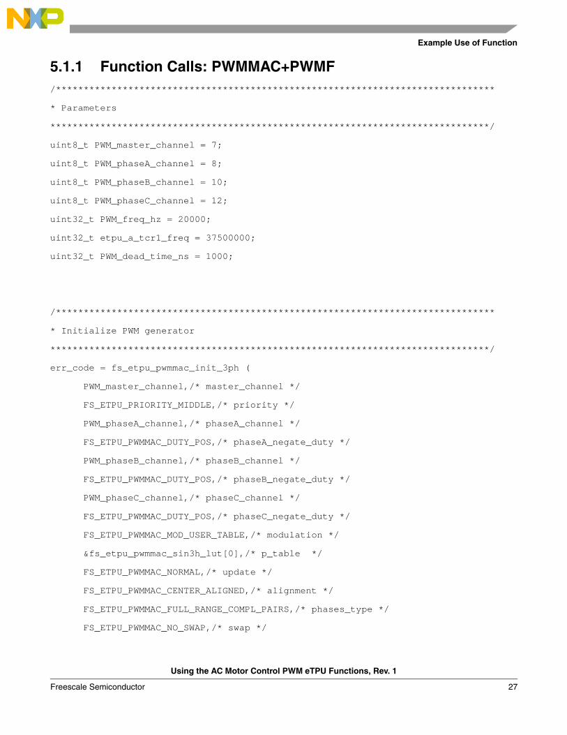
5.1.1 Function Calls: PWMMAC+PWMF/*******************************************************************************
* Parameters
*******************************************************************************/
uint8_t PWM_master_channel = 7;
uint8_t PWM_phaseA_channel = 8;
uint8_t PWM_phaseB_channel = 10;
uint8_t PWM_phaseC_channel = 12;
uint32_t PWM_freq_hz = 20000;
uint32_t etpu_a_tcr1_freq = 37500000;
uint32_t PWM_dead_time_ns = 1000;
/*******************************************************************************
* Initialize PWM generator
*******************************************************************************/
err_code = fs_etpu_pwmmac_init_3ph (
PWM_master_channel,/* master_channel */
FS_ETPU_PRIORITY_MIDDLE,/* priority */
PWM_phaseA_channel,/* phaseA_channel */
FS_ETPU_PWMMAC_DUTY_POS,/* phaseA_negate_duty */
PWM_phaseB_channel,/* phaseB_channel */
FS_ETPU_PWMMAC_DUTY_POS,/* phaseB_negate_duty */
PWM_phaseC_channel,/* phaseC_channel */
FS_ETPU_PWMMAC_DUTY_POS,/* phaseC_negate_duty */
FS_ETPU_PWMMAC_MOD_USER_TABLE,/* modulation */
&fs_etpu_pwmmac_sin3h_lut[0],/* p_table */
FS_ETPU_PWMMAC_NORMAL,/* update */
FS_ETPU_PWMMAC_CENTER_ALIGNED,/* alignment */
FS_ETPU_PWMMAC_FULL_RANGE_COMPL_PAIRS,/* phases_type */
FS_ETPU_PWMMAC_NO_SWAP,/* swap */
Using the AC Motor Control PWM eTPU Functions, Rev. 1
Freescale Semiconductor 27
Summary and Conclusions
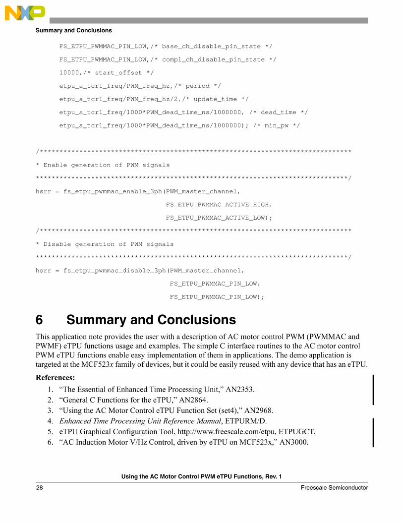
FS_ETPU_PWMMAC_PIN_LOW,/* base_ch_disable_pin_state */
FS_ETPU_PWMMAC_PIN_LOW,/* compl_ch_disable_pin_state */
10000,/* start_offset */
etpu_a_tcr1_freq/PWM_freq_hz,/* period */
etpu_a_tcr1_freq/PWM_freq_hz/2,/* update_time */
etpu_a_tcr1_freq/1000*PWM_dead_time_ns/1000000, /* dead_time */
etpu_a_tcr1_freq/1000*PWM_dead_time_ns/1000000); /* min_pw */
/*******************************************************************************
* Enable generation of PWM signals
*******************************************************************************/
hsrr = fs_etpu_pwmmac_enable_3ph(PWM_master_channel,
FS_ETPU_PWMMAC_ACTIVE_HIGH,
FS_ETPU_PWMMAC_ACTIVE_LOW);
/*******************************************************************************
* Disable generation of PWM signals
*******************************************************************************/
hsrr = fs_etpu_pwmmac_disable_3ph(PWM_master_channel,
FS_ETPU_PWMMAC_PIN_LOW,
FS_ETPU_PWMMAC_PIN_LOW);
6 Summary and ConclusionsThis application note provides the user with a description of AC motor control PWM (PWMMAC and PWMF) eTPU functions usage and examples. The simple C interface routines to the AC motor control PWM eTPU functions enable easy implementation of them in applications. The demo application is targeted at the MCF523x family of devices, but it could be easily reused with any device that has an eTPU.
References:1. “The Essential of Enhanced Time Processing Unit,” AN2353.2. “General C Functions for the eTPU,” AN2864.3. “Using the AC Motor Control eTPU Function Set (set4),” AN2968.4. Enhanced Time Processing Unit Reference Manual, ETPURM/D.5. eTPU Graphical Configuration Tool, http://www.freescale.com/etpu, ETPUGCT.6. “AC Induction Motor V/Hz Control, driven by eTPU on MCF523x,” AN3000.
Using the AC Motor Control PWM eTPU Functions, Rev. 1
Freescale Semiconductor28

THIS PAGE INTENTIONALLY LEFT BLANK
Using the AC Motor Control PWM eTPU Functions, Rev. 1
Freescale Semiconductor 29

THIS PAGE INTENTIONALLY LEFT BLANK
Using the AC Motor Control PWM eTPU Functions, Rev. 1
Freescale Semiconductor30

THIS PAGE INTENTIONALLY LEFT BLANK
Using the AC Motor Control PWM eTPU Functions, Rev. 1
Freescale Semiconductor 31
How to Reach Us:
Home Page:www.freescale.com
E-mail:[email protected]
USA/Europe or Locations Not Listed:Freescale SemiconductorTechnical Information Center, CH3701300 N. Alma School RoadChandler, Arizona 85224+1-800-521-6274 or [email protected]
Europe, Middle East, and Africa:Freescale Halbleiter Deutschland GmbHTechnical Information CenterSchatzbogen 781829 Muenchen, Germany+44 1296 380 456 (English)+46 8 52200080 (English)+49 89 92103 559 (German)+33 1 69 35 48 48 (French)[email protected]
Japan:Freescale Semiconductor Japan Ltd.HeadquartersARCO Tower 15F1-8-1, Shimo-Meguro, Meguro-ku,Tokyo 153-0064, Japan0120 191014 or +81 3 5437 [email protected]
Asia/Pacific:Freescale Semiconductor Hong Kong Ltd.Technical Information Center2 Dai King StreetTai Po Industrial EstateTai Po, N.T., Hong Kong+800 2666 [email protected]
For Literature Requests Only:Freescale Semiconductor Literature Distribution CenterP.O. Box 5405Denver, Colorado 802171-800-441-2447 or 303-675-2140Fax: [email protected]
Information in this document is provided solely to enable system and software implementers to use Freescale Semiconductor products. There are no express or implied copyright licenses granted hereunder to design or fabricate any integrated circuits or integrated circuits based on the information in this document.
Freescale Semiconductor reserves the right to make changes without further notice to any products herein. Freescale Semiconductor makes no warranty, representation or guarantee regarding the suitability of its products for any particular purpose, nor does Freescale Semiconductor assume any liability arising out of the application or use of any product or circuit, and specifically disclaims any and all liability, including without limitation consequential or incidental damages. “Typical” parameters that may be provided in Freescale Semiconductor data sheets and/or specifications can and do vary in different applications and actual performance may vary over time. All operating parameters, including “Typicals”, must be validated for each customer application by customer’s technical experts. Freescale Semiconductor does not convey any license under its patent rights nor the rights of others. Freescale Semiconductor products are not designed, intended, or authorized for use as components in systems intended for surgical implant into the body, or other applications intended to support or sustain life, or for any other application in which the failure of the Freescale Semiconductor product could create a situation where personal injury or death may occur. Should Buyer purchase or use Freescale Semiconductor products for any such unintended or unauthorized application, Buyer shall indemnify and hold Freescale Semiconductor and its officers, employees, subsidiaries, affiliates, and distributors harmless against all claims, costs, damages, and expenses, and reasonable attorney fees arising out of, directly or indirectly, any claim of personal injury or death associated with such unintended or unauthorized use, even if such claim alleges that Freescale Semiconductor was negligent regarding the design or manufacture of the part.
Freescale™ and the Freescale logo are trademarks of Freescale Semiconductor, Inc. All other product or service names are the propertyof their respective owners.© Freescale Semiconductor, Inc. 2005. All rights reserved.
AN2969Rev. 110/2005