utilising volcanic facies models in geothermal exploration
TRANSCRIPT

WPRB /INAGA Bali Seminar: Utilising Volcanic Facies Models in Geothermal Exploration PAGE 1
Utilising Volcanic Facies Models in Geothermal Exploration
Module 5

Utilising Volcanic Facies Models in Geothermal Exploration PAGE 2
Contents
1. Introduction.........................................................................................3
2. Volcanic Facies...................................................................................4 2.1 Facies Models for Subaerial Andesitic Stratovolcanoes ................ 4
2.1.1 Central Facies....................................................................................... 8 2.1.2 Proximal Facies .................................................................................... 8 2.1.3 Medial Facies........................................................................................ 9 2.1.4 Distal Facies ......................................................................................... 9
2.2 Facies Models for Rhyolitic Caldera Complexes ........................... 11 2.2.1 Intracaldera Dome Facies...................................................................11 2.2.2 Intracaldera Fill Facies........................................................................15 2.2.3 Extracaldera Proximal Facies.............................................................15 2.2.4 Extracaldera Distal Facies..................................................................17
3. Mapping Volcanic Facies.................................................................18 4. The Location of Geothermal Resources in Relation to Volcanic Facies.................................................................................19
4.1 Subaerial Andesitic Stratovolcanoes.............................................. 19 4.2 Rhyolitic Caldera Complexes........................................................... 19
5. Using Facies Models as a Stratigraphic Tool.................................21
6. Practical Exercise.............................................................................22

WPRB /INAGA Bali Seminar: Utilising Volcanic Facies Models in Geothermal Exploration PAGE 3
1. Introduction The concept of facies is widely used in the study of sedimentary rocks and also provides a useful tool for the study of volcanics. The reason for this is that since fossils are rare in volcanic piles, and extensive use of radiometric dating and rock geochemistry is generally impractical, only lithostratigraphy is left by which volcanic piles can be stratigraphically mapped. However, volcanic piles contain lithological units of very similar appearance with extremely complex distributions. Standard stratigraphic methods break down because one lithological unit can suddenly disappear or cannot be readily distinguished from others. Facies on the other hand are more continuous and have more complex and hence more distinct identifying characteristics. A facies is a contiguous body of rock with clearly identifiable unifying characteristics. A single facies can range in scale from outcrop to regional levels but is most usefully defined on an intermediate scale. The concept is very similar to that of a formation in that one of the aims is to establish a mappable body. However, volcanic facies are also inter-related to each other as parts of a volcanic centre, and the identification of a facies has predictive value, whereas this need not be the case for different formations. Different facies may be part of one formation and be made up of numerous lithological units. Therefore there are two different sets of unifying characteristic for a facies, one compositional and one spatial. The set of compositional characteristics are: what particular lithological types are present, and in what proportion? The spatial characteristics are: what is the relationship with bordering facies, and what is their distribution with respect to the eruptive centre?
WPRB /INAGA Bali Seminar: Utilising Volcanic Facies Models in Geothermal Exploration PAGE 4
2. Volcanic Facies The major compositional division in volcanic facies is between lavas, pyroclastics and epiclastics. The key features of lavas are their thickness and the degree of autobrecciation. The main features of pyroclastics are the thickness of beds and the size and nature of clasts. With regard to epiclastics it is most important to distinguish mass flow deposits from fluviatile deposits. Mineralogical characteristics may be unique to individual lithological units, rather than characterising the facies as a whole, and should be used with caution. However, this not to say that major compositional differences should be ignored. Volcanic facies vary widely between different types of compositionally different eruptive centres, and it is always possible for these to overlap, particularly where there is a significant time gap between them. On the other hand, the same eruptive centre can produce compositionally different products at different times. To determine spatial characteristics requires combining compositional data from a number of different points to identify the facies and progressive changes within it. The type of bordering facies and what direction it lies can then be predicted. The nature of the border is very important. In an undisturbed volcanic sequence, borders are usually gradational. Sharp borders indicate that either there are overlapping volcanic centres, there has been an erosional break, or there is a structural break. Facies models for the two main types of volcanic centre which commonly host exploitable geothermal systems are given below. These are andesite stratovolcanoes and rhyolitic caldera complexes.
2.1 Facies Models for Subaerial Andesitic Stratovolcanoes A number of facies models, of increasing complexity, for andesite volcanoes have been put forward. The simplest is presented in Figure 1 and defines three separate facies. It is often more useful to have four facies, although a multiplicity are possible (Figures 2, 3). However the more that are used, the closer they become to being individual lithological units, with their inherent problems, as discussed above. Four facies models are presented in Figures 4 and 5. There is some variety in the facies names between these models. The four facies which we recognise and suggest you use are the central, proximal, medial, and distal facies, as outlined below.

WPRB /INAGA Bali Seminar: Utilising Volcanic Facies Models in Geothermal Exploration PAGE 5
Figure 1 Three-facies model of a large central-vent andesitic stratovolcano (from Williams and McBirney 1979)
Figure 2 Generalised facies model for stratovolcanoes (from Cas and Wright 1988)
Central Zone
Proximal Zone
Distal Zone
v v
v vv v
vv
v vv
v v v
vv v v v v
v vvv vv
v v
vv
vv
v
v v v
v vv
v v v vv
Post-volcanic succession
Feeder/intrusive igneous bodies with alteration halo and potential porphyry and epithermal mineralization. Lavas and domes
Pyroclastic fall and volcaniclastic mass-flow deposits
Eroded remnants of pyroclastic fall deposits Coeval epiclastic sediments
Post-volcanic epiclastic sediments
Major erosion / degradation surface
Basement
Subsurface intrusive 0 5 10k
1 lahar 2 fluvial crystal-rich epiclastic sediments 3 thin plinian fall deposit 4 soil 5 fluvial channel 6 fluvial epiclastic sediments 7 ashy lake sediments
1 lahar 2 fluvial sediments 3 plinian fall deposit 4 soil 5 scoria fall deposit 6 fluvial sediments 7 lahar filling in box canyon cut into 1-6 8 block and ash deposit 9 non-welded ignimbrite 10 welded ignimbrite

WPRB /INAGA Bali Seminar: Utilising Volcanic Facies Models in Geothermal Exploration PAGE 6
Figure 3 Conceptual model of volcanic and sedimentary deposits associated with volcanoes (a) volcanic and sedimentary features (b) facies relationships (from Smith 1987)

WPRB /INAGA Bali Seminar: Utilising Volcanic Facies Models in Geothermal Exploration PAGE 7
Figure 4 Facies of a stratovolcano based on studies of Fuego, Guatemala (from Cas and Wright
1988)
Figure 5 A four facies model of an andesitic stratovolcano (from Bogie and MacKenzie 1998)
V
V
VV
V
V
VVV
V
VV
VV
V
V
V
V
V
V
V
V
X1
X1
Beach ridges
delta
Volcanic core
Proximal volcanic facies (valley entrenched pyroclastic flows)
Medial volcanic facies (alluvial fans)
Distal volcanic facies (sinuous and braided channels, flood basin and coastline)
V
X X1Lavas
Airfall deposits Pyroclastic debris flow deposits
Fluvial channels
Volcanic core facies
Proximal Volcani-clastic facies
Medial Volcani-clastic facies
Distal volcaniclastic facies
Offshore

WPRB /INAGA Bali Seminar: Utilising Volcanic Facies Models in Geothermal Exploration PAGE 8
2.1.1 Central Facies
Volcanic rocks emplaced close to volcanic vents are normally easy to recognise in the field. Most are distinguished by some combination of the following features: • consanguineous dykes, especially those that are radial or randomly oriented • consanguineous sills that are concordant with moderate to steep initial dips • breccia pipes and stocks • hydrothermal alteration with steep lateral gradients • coarse agglomerates • thick, steeply banded siliceous lavas • coarsely stratified but poorly sorted tephra • steep initial dips • thin lava flows that are volumetrically subordinate to fragmental ejecta • ponded crater - and vent-fillings with sharply divergent cooling joints
No single feature can be taken as conclusive evidence of a large central volcanic vent. For example, the fact that rhyolitic lavas are characteristic of domes and viscous flows that seldom move for more than one or two kilometres may indicate that an outcrop of such a flow is not far from its feeder, but siliceous domes are not restricted to the summits of large volcanoes; many emerge far down the lower slopes of composite cones. Similarly, coarse breccias may be found in vents but also in lahars tens of kilometres from their source. Perhaps the two most typical aspects of central-vent areas are their bewildering structural and lithologic diversity and their pervasive alteration. This facies is found within about 0.5 to 2 km from central vents.
2.1.2 Proximal Facies
The rocks laid down at increasing distances on the slopes and outer flanks of a large volcanic complex have many of the following features:
• dominated by broad, thick lavas • intercalated coarse grained pyroclastics, poorly sorted pyroclastic breccias • may be cut by consanguineous dykes • moderate to step initial dip
Few of these features provide reliable clues to the direction of the source areas but under favourable circumstances it may be possible to analyse the spatial patterns of certain features, such as the grain-size of tephra-units or the proportions of lava flows, by plotting and delineating their variations. When this is done, it is often possible to define the central focus of volcanism from the distribution of rocks in the proximal and central zones. This facies surrounds the central facies, and extends up to 5 to 10 km from central vents.

WPRB /INAGA Bali Seminar: Utilising Volcanic Facies Models in Geothermal Exploration PAGE 9
2.1.3 Medial Facies • pyroclastics dominate over lavas • lahars with angular or subangular blocks up to 10 m or so in diameter • tephra layers with good sorting and grain sizes mainly in the lapilli to coarse ash range • zones of weathering and soil development (paleosols) between lava flows • clastic debris reworked by water • moderate to shallow dips
This facies is located up to 10 to 15 km from central vents.
2.1.4 Distal Facies
Volcanic rocks laid down well beyond the base of a large volcano tend to have a greater lateral continuity than those of inner zones and they conform more closely to conventional stratigraphic criteria, as epiclastics predominate. The features of these outlying areas include:
• fine layered tephra with grain sizes in the range of coarse to fine ash, and with an outward-
increasing ratio of glass to crystals • lahars with blocks that rarely exceed a metre in diameter and have rounded or subrounded
particles in their matrix • interlayered shallow-water sediments, soils, and organic debris • lava flows restricted mainly to isolated vents, basaltic sheets, and intra-canyon flows
As in the proximal zone, there are few criteria that provide reliable clues to the direction of the source area of individual units, but with sufficient data on grain size or thickness variations of distinctive units it may be possible to deduce distribution patterns centring on a source. It must be borne in mind, however, that the vagaries of wind currents and moving water diminish the reliability of these techniques and make them less valuable than a direct identification of the central and proximal zones. This facies is located more than 10 to 15 km from central vents. Proximal and medial facies are deposited on the slopes of volcanoes and will form sequences dipping away from the centre, at the angle of their repose, whereas distal facies will be relatively flat lying, occurring on the ring plain around the volcanic centre. These facies will all relate to one individual eruptive centre, however typically andesite stratovolcanoes are more complex. The central vent may move with time, they may contain overlapping eruptive centres and have parasitic cones. Therefore some care is required to separate out separate eruptive centres. Three cross-sections are presented in Figures 6, 7 and 8, to illustrate these variations.

WPRB /INAGA Bali Seminar: Utilising Volcanic Facies Models in Geothermal Exploration PAGE 10
Figure 6 Broken Top volcano, Oregon. Note the migration of the eruptive centre (from Wohletz
and Heiken 1992)
Figure 7 Mount Hood volcano, Oregon. Note the overlapping volcanic cones (Wohletz and Heiken 1992)

WPRB /INAGA Bali Seminar: Utilising Volcanic Facies Models in Geothermal Exploration PAGE 11
Figure 8 Composite of PNG volcanoes, showing parasitic cones (from Wohletz and Heiken 1992)
2.2 Facies Models for Rhyolitic Caldera Complexes Numerous overall models and cross-sections of rhyolitic caldera complexes have been presented in the literature (e.g. Figures 9, 10 and 11). A facies model (Figure 12) was constructed by Cas and Wright (1988). Actual facies names are not defined. Here we take a similar approach to that taken for andesite stratovolcanoes, with four facies. As the eruptive centres and their products are much larger than andesite stratovolcanoes, the facies are also much larger in scale.
2.2.1 Intracaldera Dome Facies This facies usually develops at a late stage in the formation of a caldera complex and consists of rhyolitic lava domes and short flows with autobreccia carapaces and aprons, associated near-vent pyroclastic falls, and other rhyolitic pyroclastics that are coarse and of limited extent. Minor basalt scoria cones may be present. Rhyolite domes may be found on the caldera rim and in clusters or lines within the caldera.

WPRB /INAGA Bali Seminar: Utilising Volcanic Facies Models in Geothermal Exploration PAGE 12
Figure 9 Model for formation of Toba caldera, Sumatra (Williams and McBirney 1979). Elevations
in m, 5x vertical exaggeration
Tertiary
Basic-intermediate magma and
Siliceous
Granitic batholith
Siliceous
0 80 km 40
SW NE
Indian Ocean
Samosir Pintau
vvv v
v
vvvv
vvv
vv
v vvvv v
vvvvvv v
vv
vv
v vv
vvvv vv
vv v
vv v
vv v
vv v v
vv vv v

WPRB /INAGA Bali Seminar: Utilising Volcanic Facies Models in Geothermal Exploration PAGE 13
Figure 10 Evolution of a large silicic caldera: (a) volcanism prior to caldera collapse, (b) immediately
after collapse, (c) resurgence (from Wohletz and Heiken 1992)

WPRB /INAGA Bali Seminar: Utilising Volcanic Facies Models in Geothermal Exploration PAGE 14
Figure 11 Model for caldera formation (Browne and Houghton 1984) The size of this facies is obviously dependent upon the size of the caldera it occupies. In extreme examples, much of the caldera can be occupied by the dome complex, but in a medium sized caldera of 10 to 20 km diameter, the range is typically from 1 to 10 km.
Country rock
Magma
Ignimbrite
Lava domes and crystalline intrusive
Ash cloud
lake
A
B
C
D
E
F

WPRB /INAGA Bali Seminar: Utilising Volcanic Facies Models in Geothermal Exploration PAGE 15
2.2.2 Intracaldera Fill Facies This facies is formed during initial creation of the caldera, and underlies the intracaldera dome facies. At the caldera margins there may be collapse breccias interbedded with ignimbrite. Very thick crystal rich ignimbrites with co-ignimbrite lag fall breccias and interbedded epiclastics, most particularly lacustrine deposits, make up the caldera fill. There are some very large calderas, but 10 to 20 km can be taken as a median size.
Figure 12 Facies model for silicic calderas (from Cas and Wright 1988)
2.2.3 Extracaldera Proximal Facies
This facies contains the eruptive material produced by the eruption which initiated caldera formation and subsequent eruptions from the caldera. It consists of interbedded, mainly thick, ignimbrite and

WPRB /INAGA Bali Seminar: Utilising Volcanic Facies Models in Geothermal Exploration PAGE 16
airfall rhyolitic tuffs and minor rhyolitic domes and basalt scoria cones. The ignimbrites will commonly have welded centres and contain coarse lithic clasts. The distance that this facies extends from the caldera will vary with the size of the caldera, for the median size caldera a distance of up to 10 to 20 km can be taken.
Figure 13 Matahina Ignimbrite, New Zealand: (a) isopach map (thickness in m), and (b) size distribution (in cm) of lithic clasts (ML - 5 = average diameter of the five largest clasts in c. 4m2 of outcrop) (from Bailey and Carr 1994)

WPRB /INAGA Bali Seminar: Utilising Volcanic Facies Models in Geothermal Exploration PAGE 17
2.2.4 Extracaldera Distal Facies
This distal facies comprises layered, mainly thin, and mainly un-welded ignimbrites with fine clasts, and volcanogenic epiclastics. The ignimbrites will be dissected, with epiclastics filling erosional channels as well as being interbedded with the epiclastics. The pre-eruption topography must be taken into account, as it is possible for ignimbrites to pond and have variable thicknesses. For example, if it ponds very close to its source it will be thin even in the proximal zone. Alternatively, it could pond far from the source and be relatively thick there. Therefore the thickness of an individual ignimbrite is not sufficient on its own to define the facies. Similarly, care must be used in assessing the grain size of clasts; only denser lithic clasts should be assessed, not pumice clasts which can have extremely erratic distributions. This can be seen in the comparison of isopach and lithic size distribution maps of the Matahina Ignimbrite from the Taupo Volcanic Zone, New Zealand (Figure 13). Thickness (isopach) mapping might suggest a source to the south; however the lithic clast size distribution identifies a westerly source from the Haroharo caldera (Figure 13b). Once again, there is significant variation in the distance of this facies from a caldera, but for the median case, 10 to 100 km is usual.

WPRB /INAGA Bali Seminar: Utilising Volcanic Facies Models in Geothermal Exploration PAGE 18
3. Mapping Volcanic Facies An outcrop map, containing only data with no interpretive material should be prepared. This should indicate outcrop locations and structural information such as strike and dip symbols. Detailed notes for each outcrop should be made. These should include:
• What proportion of lavas, pyroclastics and epiclastics are present. • If lava is present, how thick it is, what proportion of it is auto-brecciated, and whether there are
any indications of flow direction; for example, aligned phenocrysts. Phenocryst mineralogy and any distinct textures such as banding or other identifying characteristics, for example abundant xenoliths, should be recorded.
• If pyroclastic material is present, minimum, average and maximum clast sizes and proportions
should be recorded, and if the clasts are poorly sorted or polymodal, clast or matrix-supported, and if there is any rounding of the clasts. The proportion of lithic, crystal and vitric clasts should be established. Any bedding features and any extraneous material should be noted. For example, wood may be present, and should be examined to see if there is any charring, and a sample collected for possible radiocarbon dating.
• If epiclastic material is present, minimum, average and maximum clast sizes and proportions
should be recorded, and if the clasts are poorly sorted or polymodal, clast or matrix-supported, and if there is any rounding of the clasts. Any bedding or sedimentary textures should be noted, and any fossils collected. Where limestones or calcareous siltstones are found, samples should be collected for micro-palaeontology.
Rock names can then be assigned to each lithology described, and each outcrop as a whole assigned to a facies, although it may require information from a number of contiguous outcrops to do this. A facies map can then be prepared as an overlay to the outcrop map. Great attention should be paid to the boundaries between facies, so as to distinguish unconformities, different eruptive centres and structural breaks. The structural information on the outcrop map can be used to distinguish these alternatives. The facies can then be grouped into separate eruptive centres. Once the area of each individual facies has been established, systematic variations in clast sizes, lithological unit thickness and other criteria discussed above for establishing the vent direction within an individual facies should be determined. This process should be done independently for each facies in each eruptive centre. The results from each facies should then be compared. Not only should the indicated directions all point to one centre, but the relationship of facies around the centre should be in agreement. If they are not in agreement, the assignment to different eruptive centres should be reviewed and new eruptive centres defined until there is agreement. This is a major strength of the method as it allows an internal check of its veracity. It should be stressed that this approach to field mapping is a supplement to normal exploration mapping and should be used in conjunction with mapping formations and hydrothermal alteration.

WPRB /INAGA Bali Seminar: Utilising Volcanic Facies Models in Geothermal Exploration PAGE 19
4. The Location of Geothermal Resources in Relation to Volcanic Facies
4.1 Subaerial Andesitic Stratovolcanoes Geothermal resources associated with subaerial andesite stratovolcanoes usually have their upflows associated with the most recent volcanic centre. This will often contain differentiated lavas, particularly dacites, containing hornblende as a phenocryst phase. The upflow of the system is likely to occur beneath the surficial proximal facies, with the outflow going below the medial facies. The outflow may continue out into the distal facies, but will usually be at a temperature unattractive for electrical power generation this far from the upflow. The central facies of young eruptive centres can host thermal activity, but it is usually of a magmatic character and may not be indicative of an exploitable resource.
4.2 Rhyolitic Caldera Complexes The relationship between rhyolitic caldera complexes and active hydrothermal systems can be illustrated by considering the distribution of active geothermal fields, calderas and widespread ignimbrite sheets in the Taupo Volcanic Zone, New Zealand (Figure 14). Whilst only a few of the systems occur inside calderas, all are within 20 km of a caldera, and it is possible that more calderas are present than indicated. There are two opposing viewpoints regarding the relationship of calderas and hydrothermal systems. One, propounded by geophysicists, is that both calderas and hydrothermal systems are the expected products of rhyolitic magmatism, and their occurrence together is purely fortuitous. The other is that hydrothermal systems are intimately related to calderas in this setting, and that where a system is present, apparently without a caldera, this is because obvious signs of a caldera have been obscured. Whatever the case, the systems are occurring beneath either Intracaldera Fill Facies or Extracaldera Proximal Facies.

WPRB /INAGA Bali Seminar: Utilising Volcanic Facies Models in Geothermal Exploration PAGE 20
Figure 14 Distribution of active geothermal fields, ignimbrites and calderas in the Taupo Volcanic Zone, New Zealand (from Browne and Houghton 1984)

WPRB /INAGA Bali Seminar: Utilising Volcanic Facies Models in Geothermal Exploration PAGE 21
5. Using Facies Models as a Stratigraphic Tool As discussed above, the lithostratigraphy of volcanic piles can be complex. By mapping facies, a formation can be defined as the eruptive products of a single volcanic centre. Where there is a systematic gradational change in facies, the position of the eruptive centre can be established. Where there is a sudden non-systematic change in facies this is likely to be a formational boundary. Such changes are best observed in continuously cored holes, as important textural information, such as the size of large clasts cannot be established from cuttings. However formational imaging tools such as the FMI and FMS can supply this information, at least in the upper parts of wells where their use is not temperature limited. They can also provide information on initial dips which can help in defining facies, as these increase toward eruptive centres.
WPRB /INAGA Bali Seminar: Utilising Volcanic Facies Models in Geothermal Exploration PAGE 22
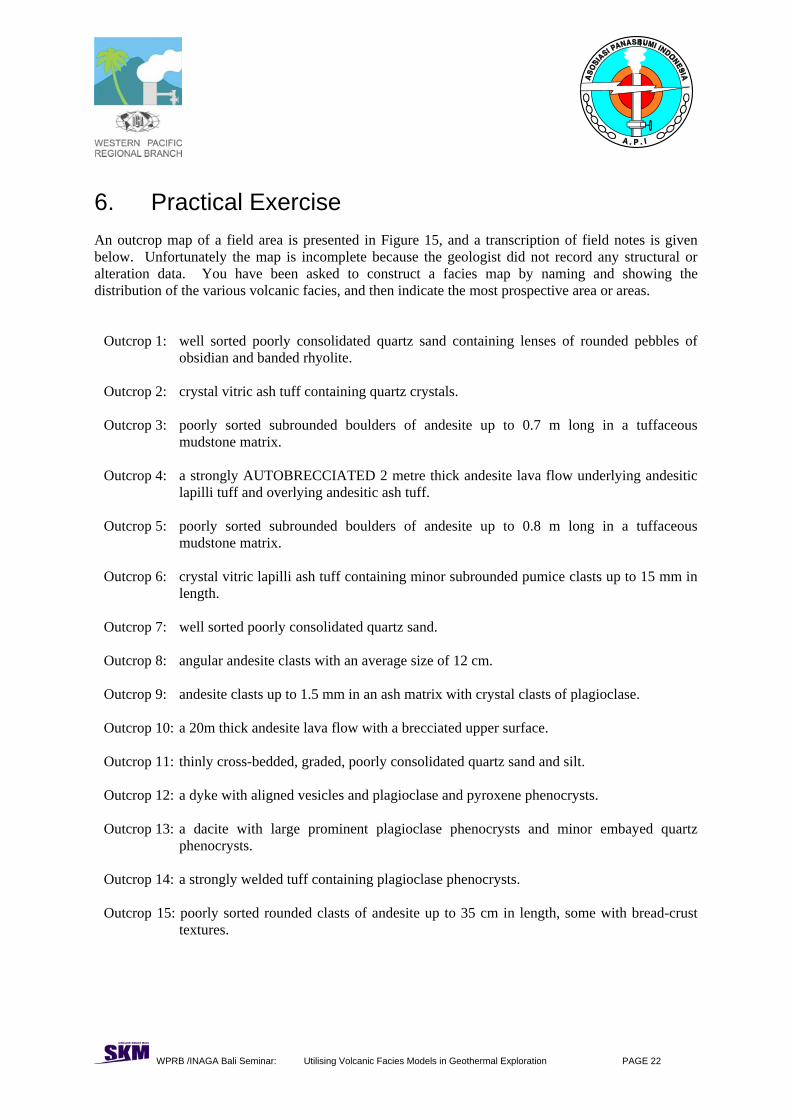
6. Practical Exercise An outcrop map of a field area is presented in Figure 15, and a transcription of field notes is given below. Unfortunately the map is incomplete because the geologist did not record any structural or alteration data. You have been asked to construct a facies map by naming and showing the distribution of the various volcanic facies, and then indicate the most prospective area or areas.
Outcrop 1: well sorted poorly consolidated quartz sand containing lenses of rounded pebbles of obsidian and banded rhyolite.
Outcrop 2: crystal vitric ash tuff containing quartz crystals. Outcrop 3: poorly sorted subrounded boulders of andesite up to 0.7 m long in a tuffaceous
mudstone matrix. Outcrop 4: a strongly AUTOBRECCIATED 2 metre thick andesite lava flow underlying andesitic
lapilli tuff and overlying andesitic ash tuff. Outcrop 5: poorly sorted subrounded boulders of andesite up to 0.8 m long in a tuffaceous
mudstone matrix. Outcrop 6: crystal vitric lapilli ash tuff containing minor subrounded pumice clasts up to 15 mm in
length. Outcrop 7: well sorted poorly consolidated quartz sand. Outcrop 8: angular andesite clasts with an average size of 12 cm. Outcrop 9: andesite clasts up to 1.5 mm in an ash matrix with crystal clasts of plagioclase. Outcrop 10: a 20m thick andesite lava flow with a brecciated upper surface. Outcrop 11: thinly cross-bedded, graded, poorly consolidated quartz sand and silt. Outcrop 12: a dyke with aligned vesicles and plagioclase and pyroxene phenocrysts. Outcrop 13: a dacite with large prominent plagioclase phenocrysts and minor embayed quartz
phenocrysts. Outcrop 14: a strongly welded tuff containing plagioclase phenocrysts. Outcrop 15: poorly sorted rounded clasts of andesite up to 35 cm in length, some with bread-crust
textures.
WPRB /INAGA Bali Seminar: Utilising Volcanic Facies Models in Geothermal Exploration PAGE 23
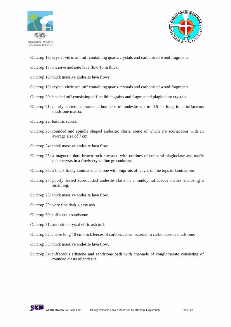
Outcrop 16: crystal vitric ash tuff containing quartz crystals and carbonised wood fragments. Outcrop 17: massive andesite lava flow 15 m thick. Outcrop 18: thick massive andesite lava flows. Outcrop 19: crystal vitric ash tuff containing quartz crystals and carbonised wood fragments. Outcrop 20: bedded tuff consisting of fine lithic grains and fragmented plagioclase crystals. Outcrop 21: poorly sorted subrounded boulders of andesite up to 0.5 m long in a tuffaceous
mudstone matrix. Outcrop 22: basaltic scoria. Outcrop 23: rounded and spindle shaped andesitic clasts, some of which are scoriaceous with an
average size of 7 cm. Outcrop 24: thick massive andesite lava flow. Outcrop 25: a magnetic dark brown rock crowded with outlines of euhedral plagioclase and mafic
phenocrysts in a finely crystalline groundmass. Outcrop 26: a black finely laminated siltstone with imprints of leaves on the tops of laminations. Outcrop 27: poorly sorted subrounded andesite clasts in a muddy tuffaceous matrix enclosing a
small log. Outcrop 28: thick massive andesite lava flow. Outcrop 29: very fine dark glassy ash. Outcrop 30: tuffaceous sandstone. Outcrop 31: andesitic crystal vitric ash tuff. Outcrop 32: metre long 10 cm thick lenses of carbonaceous material in carbonaceous mudstone. Outcrop 33: thick massive andesite lava flow. Outcrop 34: tuffaceous siltstone and sandstone beds with channels of conglomerate consisting of
rounded clasts of andesite.

WPRB /INAGA Bali Seminar: Utilising Volcanic Facies Models in Geothermal Exploration PAGE 24
Outcrop 35: very fine dark glassy ash. Outcrop 36: well sorted magnetite rich sand. Outcrop 37: reef limestone. Outcrop 38: 5 m long boulders of andesite in a poorly sorted matrix of tuff and smaller andesite
clasts. Outcrop 39: lapilli sized clasts of andesite in metre-thick beds between plagioclase crystal rich tuffs.

WPRB /INAGA Bali Seminar: Utilising Volcanic Facies Models in Geothermal Exploration PAGE 25
23
4
5
7
6
9 1012
1316
1
8
15 1411
24 1718 19
20 22 3825
21
3923
26 2728
29 30
3133
34 32 35 3637
Vmod7_24
Figure 15 Outcrop location map for practical exercise