utility poles brochure
TRANSCRIPT

Utility Poles

>> Oceania’s most experienced and versatile supplier of quality, engineered overhead line structures.
Bass Link, austraLia

At INGAL EPS, we’ve being designing and producing utility poles since the early days of the company’s start-up back in 1969; producing octagonal distribution poles for the Western Australian utility market. Over the years we’ve grown significantly and poles with ultimate tip loads approaching 900kN are now not uncommon.
INGAL EPS has a dedicated utility structure design team, quality assured manufacturing processes and superior before and after sales service. INGAL EPS is now established as Oceania’s most versatile utility pole supplier. No other overhead line structure company can cover the full range of structures we can; from our standard range of distribution poles through to the most detailed and heavily loaded structures you could possibly need.
The engineering and raw materials that go into our structures are second to none and you have the comfort of knowing your structures are backed by the experience and security of the largest pole company in the world.
Whatever you need, we’ve got it covered.

OtagOnet, new ZeaLand

UTILITy POLES | Page 5
Standard PolesINGAL EPS’ Standard Utility Poles are the lightest poles available across the full range of length and tip loads. All of the standard range conforms to AS/NZS standards and ASCE/SEI 48-11. The length and tip loads of the standard range allow INGAL EPS steel poles to be a direct replacement for most timber and concrete poles, with the addition of some significant advantages.
Our standard range of in-ground and base plate mounted poles come with the offer of PLS Pole data to give asset owners and consultants real-time checking of our structures at the desktop.
Key Benefits• Lightest poles across the full range of length and tip loads• Conform to all relevant AS/NZS standards• Conform to ASCE/SEI 48-11• Impervious to insects and rot• Non-combustible with proven bush fire performance• Tapered design enables self-cleaning during rainfall• Fully recyclable• Self-bonding• PLS Pole data available
Standard Features In-Ground Mounted
• 12-sided pole shaft• Welded top cap• Mounting holes (to your specification if required)• Identification plate• M12 earth point 250mm above the nominal ground line• M24 nut 250mm above the nominal ground line
(to assist lifting)• Additional in-ground corrosion protection 200mm above to
400mm below the nominal ground line• Anti-sink straps• Hot dip galvanised finish
Standard Features Base Plate Mounted
• 12-sided pole shaft (40kN to 80kN)• 16-sided pole shaft (100kN & 120kN)• Welded top cap• Mounting holes (to your specification if required)• Identification plate• M12 earth point 250mm above the pole base• Two lifting gussets on the base plate• Anchor bolts, templates, nuts & washers• Hot dip galvanised finish
Pole Shaft and Top CapPole shafts are manufactured from sheet or plate steel that has a minimum tensile strength of 450MPa. The welded top cap is usually made from Grade 250 equivalent steel or greater and is not a structural element of the pole. Shafts are all 12 and 16-sided to allow flat mounting faces for lateral stability and ease of mounting cross arms and other hardware.
Mounting HolesPoles can be supplied with or without mounting holes. Drilling mounting holes at the time of dressing a pole is simple and carried out in very much the same way as a timber pole. When holes are drilled post galvanising, we recommend the use of an organic zinc rich primer on the exposed surfaces prior to assembly.
Standard steel poles could have 22mm through-holes (two holes at the same level and at 180 degree apart), every 75mm down the pole with negligible affect on the strength. In general, 22mm holes could be spaced closer at 50mm apart for groups of six to ten through holes without significantly affecting the design capacity of the overall pole.
Generally up to four to eight 22mm holes on adjacent flats of the pole could be placed at the same level if required. The section capacity at that level will be slightly lower but generally the overall pole design capacity should still be able to be achieved.

Page 6 | UTILITy POLES
Anti-Sink Straps and PlatesAll in-ground poles are provided with anti-sink straps or a plate to attach across the bottom of the base section. Distribution poles are supplied with a single strap and sub transmission/transmission poles with two straps or an anti-sink plate (depending on the weight & load capacity of the pole). Straps and plates are hot dip galvanised and are provided with securing bolts to attach to the pole prior to installation.
Hot Dip GalvanisingAll hot dip galvanising is carried out to conform to ASTM A123 and in doing so automatically meets the minimum coating thickness requirements of AS/NZS 4680.
Cross ArmsTimber, steel and composite cross arms can all be mounted to INGAL EPS steel poles in virtually the same manner as they are mounted to timber poles. No special brackets or cross arm modifications are required.
Transformer Mounting and Transition ArrangementsThe sufficiency of a steel pole to take a transformer is governed by the moment capacity of the steel section at and below the transformer mounting position and in any case the steel pole’s ability to carry moment is not inferior to equivalent timber or concrete products.
Similarly, you can treat INGAL EPS steel poles in the same manner for transition cables as you would with a timber pole. The only difference need be the use of a drill bit suitable for drilling steel instead of timber.
Ultimate Tip LoadsAll ultimate tip loads for standard poles conform to both AS/NZS and ASCE standards for steel pole structures. The design tip load allows for the pole self-weight and assumes no additional vertical load for distribution poles and a small nominal vertical load for sub-transmission poles. The effect of vertical load should be considered in assessing the suitability of a specific tip load rated pole. INGAL EPS can assist with this if required.
Pole Assembly and HandlingPoles with an overall length above 12.5m are supplied in multiple sections. These poles require joining (slipping). The pole slipping and handling process is quite simple and Technical Instructions are available. INGAL EPS staff can also be made available for on-site instruction.
Note that although a measurement is used to check the pole has been slipped properly, all slip joints are completed to a compressive force applied by a wire rope hand winch (or hydraulically) first. After assembly it is safe working practice to temporarily brace the sections together for a crane or helicopter lift. If any aspect of these two points is unclear, please contact INGAL EPS for technical assistance.
Pole InstallationThe installation process is very much the same as for other pole types used by electrical utilities. If required installation instructions are readily available from INGAL EPS.
Additional In-Ground Corrosion ProtectionHot dip galvanising provides an excellent means of corrosion protection above ground and in many circumstances this is all that is required below ground when direct burying poles. However, in some areas soil conditions are such that additional in-ground protection is desirable to extend the life of the pole.
The rationale behind additional in-ground corrosion protection is that by separating soil and oxygen from the metal, you eliminate oxidisation.
Empirical evidence gathered over years of experience and research into conditions and performance of products in other markets extending back much further has led INGAL EPS to recommend these two options for additional in-ground protection; concrete encasing or a high quality polyurea coating.
Concrete encasing is a time proven performer for additional ground line protection. Concrete encasing is not to be confused with foundation mounted poles as encasing is only required from just above the ground line to a depth of around 400mm to 600mm to provide additional protection. It is important to note that when finishing off the concrete above the ground line, a smooth, tapered surface is recommended. This ensures that any contaminants are readily washed away from the pole interface with the concrete during rainfall.
Polyurea coatings also provide a tough barrier between the pole and the soil with the additional benefit of not requiring concrete on site for the pole installation. All standard poles are supplied with a polyurea coating that extends from 200mm above the nominal ground line to 600mm below.
Whether you choose one of our recommendations or specify based on your own preferences, INGAL EPS can apply it so it’s ready to go in the ground when it’s delivered.
Earth PointPrior to galvanising, an M12 steel nut is welded to the pole 250mm above the nominal ground line to serve as an earth point. A hole is drilled in the pole prior to welding the nut on to allow clearance for an M12 bolt to pass through the nut.
Lifting PointsIn-ground poles up to 3.2T in total weight are manufactured with an M24 nut welded to the pole at 180 degrees to the M12 earth point. The M24 nut is provided to assist in the pole lifting and installation, as detailed in the applicable INGAL EPS Technical Instruction. The safe working load of the nut is limited to 3.2T as the lifting eyebolt recommended in the relevant Technical Instruction is limited to 3.2T. If using a different lifting eyebolt than recommended by INGAL EPS, care should be taken to ensure the safe working load is modified to suit.
In-ground poles above 3.2T in total weight are supplied with a lifting lug welded to the pole face. The safe working load of this lug is 11.0T and is suitable for lifting all in-ground poles over 3.2T in the standard range.
For base plate mounted poles, two lifting points are provided at the base of the pole in the form of a gussets welded between the base plate and the pole shaft. The gussets have a 32mm hole drilled into them to allow for the attachment of a shackle.
UTILITy POLES | Page 7
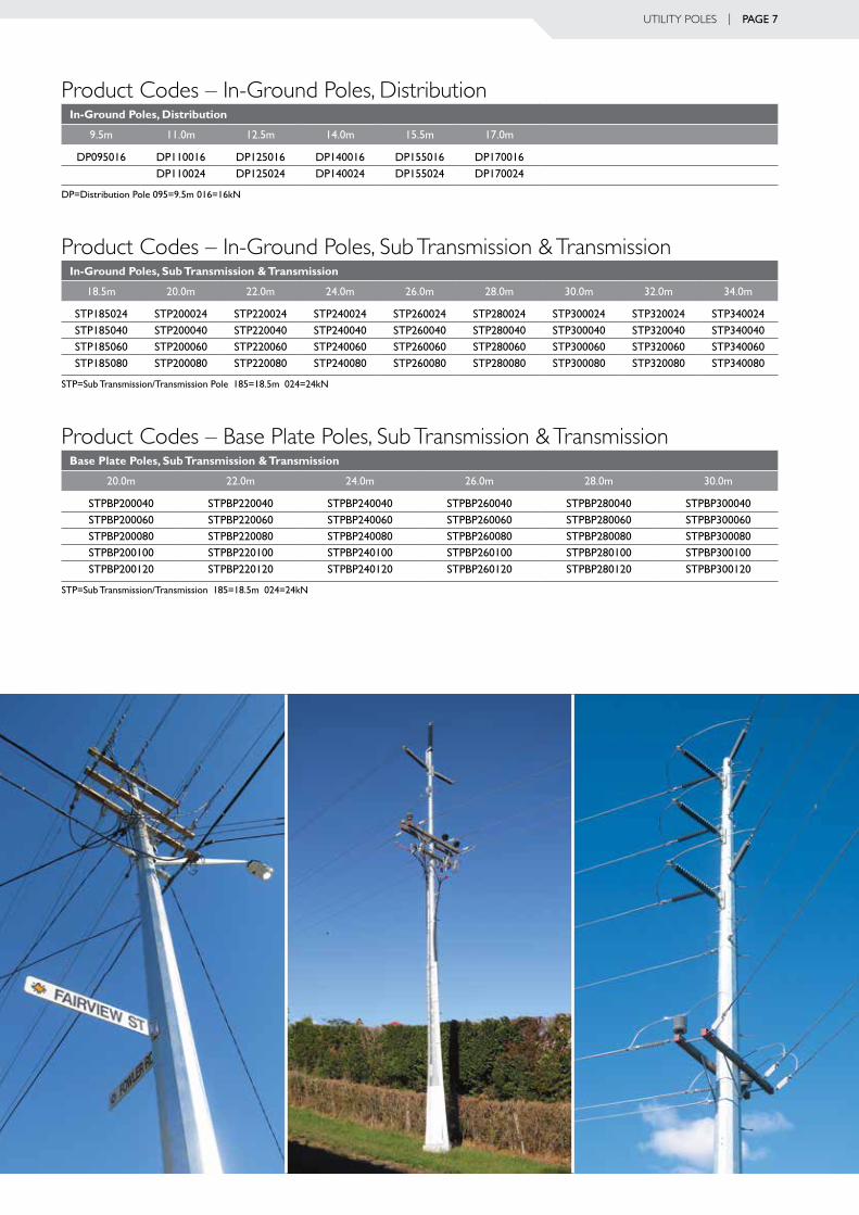
Product Codes – In-Ground Poles, DistributionIn-Ground Poles, Distribution
9.5m 11.0m 12.5m 14.0m 15.5m 17.0m
dP095016 dP110016 dP125016 dP140016 dP155016 dP170016dP110024 dP125024 dP140024 dP155024 dP170024
dP=distribution Pole 095=9.5m 016=16kn
Product Codes – In-Ground Poles, Sub Transmission & TransmissionIn-Ground Poles, Sub Transmission & Transmission
18.5m 20.0m 22.0m 24.0m 26.0m 28.0m 30.0m 32.0m 34.0m
stP185024 stP200024 stP220024 stP240024 stP260024 stP280024 stP300024 stP320024 stP340024stP185040 stP200040 stP220040 stP240040 stP260040 stP280040 stP300040 stP320040 stP340040stP185060 stP200060 stP220060 stP240060 stP260060 stP280060 stP300060 stP320060 stP340060stP185080 stP200080 stP220080 stP240080 stP260080 stP280080 stP300080 stP320080 stP340080
stP=sub transmission/transmission Pole 185=18.5m 024=24kn
Product Codes – Base Plate Poles, Sub Transmission & TransmissionBase Plate Poles, Sub Transmission & Transmission
20.0m 22.0m 24.0m 26.0m 28.0m 30.0m
stPBP200040 stPBP220040 stPBP240040 stPBP260040 stPBP280040 stPBP300040stPBP200060 stPBP220060 stPBP240060 stPBP260060 stPBP280060 stPBP300060stPBP200080 stPBP220080 stPBP240080 stPBP260080 stPBP280080 stPBP300080stPBP200100 stPBP220100 stPBP240100 stPBP260100 stPBP280100 stPBP300100stPBP200120 stPBP220120 stPBP240120 stPBP260120 stPBP280120 stPBP300120
stP=sub transmission/transmission 185=18.5m 024=24kn

Page 8 | UTILITy POLES
Prod
uct
Det
ails
PrO
du
ct
cO
de
dr
aw
ing
nO
.Le
ng
th
(m
)
uLt
imat
e t
iP L
Oa
d
(kn
)w
eig
ht
(k
g)
POLe
dia
met
er (
mm
)n
um
Ber
O
f
sec
tiO
ns
nO
min
aL
in-g
rOu
nd
d
ePt
h (
m)
Ba
se P
Lat
e d
iam
eter
nu
mBe
r
Of
m
30 B
OLt
sPc
d
(mm
)
def
Lec
tiO
n
at 5
0% O
f u
Ltim
ate
(%)
tOP
Ba
se
In-G
roun
d Po
les,
Dis
trib
utio
n
dP0
9501
6g
a25
439.
516
224
125
330
11.
55-
--
3.5
dP1
1001
6g
a25
4411
.016
279
125
362
11.
70-
--
3.9
dP1
1002
4g
a25
4511
.024
343
155
440
11.
70-
--
3.2
dP1
2501
6g
a25
4612
.516
338
125
395
11.
85-
--
4.2
dP1
2502
4g
a25
4712
.524
413
155
479
11.
85-
--
3.4
dP1
4001
6g
a25
4814
.016
429
135
413
22.
00-
--
4.4
dP1
4002
4g
a25
4914
.024
532
160
517
22.
00-
--
3.5
dP1
5501
6g
a25
5015
.516
496
135
444
22.
15-
--
4.6
dP1
5502
4g
a25
5115
.524
616
160
556
22.
15-
--
3.7
dP1
7001
6g
a25
5217
.016
568
135
475
22.
30-
--
4.8
dP1
7002
4g
a25
5317
.024
706
160
595
22.
30-
--
3.8
In-G
roun
d Po
les,
Sub
Tra
nsm
issi
on
& T
rans
mis
sio
n
stP1
8502
4g
a31
6218
.524
838
180
639
22.
45-
--
3.7
stP1
8504
0g
a31
6318
.540
1,23
625
570
82
2.45
--
-3.
0st
P185
060
ga
4474
18.5
601,
696
310
774
22.
60-
--
2.7
stP1
8508
0g
a44
6918
.580
2,04
538
082
62
2.80
--
-2.
4st
P200
024
ga
3164
20.0
2494
118
067
72
2.60
--
-3.
8st
P200
040
ga
3165
20.0
401,
379
255
746
22.
60-
--
3.2
stP2
0006
0g
a31
6620
.060
1,86
331
081
32
2.80
--
-2.
8st
P200
080
ga
4468
20.0
802,
278
380
864
23.
00-
--
2.5
stP2
2002
4g
a31
6722
.024
1,10
218
072
72
2.80
--
-3.
9st
P220
040
ga
3168
22.0
401,
598
255
796
22.
80-
--
3.3
stP2
2006
0g
a31
6922
.060
2,14
731
086
42
3.00
--
-3.
0st
P220
080
ga
3170
22.0
802,
606
380
913
23.
20-
--
2.7
stP2
4002
4g
a31
7124
.024
1,31
618
076
93
3.00
--
-4.
0st
P240
040
ga
3172
24.0
401,
898
255
835
33.
00-
--
3.5
stP2
4006
0g
a31
7324
.060
2,54
631
090
23
3.20
--
-3.
2st
P240
080
ga
3174
24.0
803,
109
380
948
33.
40-
--
2.9
stP2
6002
4g
a31
7526
.024
1,67
018
081
93
3.20
--
-3.
8st
P260
040
ga
3176
26.0
402,
125
255
885
33.
20-
--
3.6
stP2
6006
0g
a31
7726
.060
2,84
031
095
43
3.40
--
-3.
3st
P260
080
ga
3178
26.0
803,
467
380
997
33.
60-
--
3.1
stP2
8002
4g
a44
8228
.024
1,84
518
087
03
3.40
--
-4.
0st
P280
040
ga
4478
28.0
402,
417
255
935
33.
40-
--
3.7
stP2
8006
0g
a44
7328
.060
3,21
831
01,
006
33.
60-
--
3.4
stP2
8008
0g
a44
6728
.080
3,92
438
01,
047
33.
80-
--
3.2
stP3
0002
4g
a44
8130
.024
2,08
018
092
03
3.60
--
-3.
9

UTILITy POLES | Page 9st
P300
040
ga
4477
30.0
402,
878
255
985
33.
60-
--
3.7
stP3
0006
0g
a44
7230
.060
3,54
631
01,
057
33.
80-
--
3.5
stP3
0008
0g
a44
6630
.080
4,31
938
01,
097
34.
00-
--
3.3
stP3
2002
4g
a44
8032
.024
2,32
918
097
13
3.80
--
-3.
9st
P320
040
ga
4476
32.0
403,
198
255
1,03
63
3.80
--
-3.
6st
P320
060
ga
4471
32.0
603,
889
310
1,10
93
4.00
--
-3.
6st
P320
080
ga
4465
32.0
804,
733
380
1,14
73
4.20
--
-3.
4st
P340
024
ga
4479
34.0
242,
733
180
1,01
04
4.00
--
-3.
9st
P340
040
ga
4475
34.0
403,
600
255
1,07
44
4.00
--
-3.
8st
P340
060
ga
4470
34.0
604,
707
310
1,14
74
4.20
--
-3.
6st
P340
080
ga
4459
34.0
805,
436
380
1,18
14
4.40
--
-3.
5
Bas
e P
late
Po
les,
Sub
Tra
nsm
issi
on
& T
rans
mis
sio
n
stPB
P200
040
ga
4487
20.0
401,
496
255
746
2-
970
1688
03.
4st
PBP2
0006
0 g
a44
8820
.060
1,99
431
081
32
-10
4020
950
3.1
stPB
P200
080
ga
4489
20.0
802,
394
380
864
2-
1090
2010
002.
8st
PBP2
0010
0 g
a44
9020
.010
02,
724
430
999
2-
1230
2411
402.
3st
PBP2
0012
0 g
a44
9120
.012
03,
018
447
960
2-
1190
2811
002.
6st
PBP2
2004
0 g
a44
9222
.040
1,67
625
579
62
-10
2016
930
3.5
stPB
P220
060
ga
4493
22.0
602,
402
310
864
2-
1090
2010
003.
2st
PBP2
2008
0 g
a44
9422
.080
2,73
038
091
32
-11
4024
1050
2.9
stPB
P220
100
ga
4495
22.0
100
3,09
743
01,
057
2-
1290
2412
002.
5st
PBP2
2012
0 g
a44
9622
.012
03,
476
447
1,01
22
-12
5028
1160
2.8
stPB
P240
040
ga
4497
24.0
401,
978
255
835
3-
1060
1697
03.
7st
PBP2
4006
0 g
a44
9824
.060
2,66
831
090
33
-11
4020
1050
3.4
stPB
P240
080
ga
4499
24.0
803,
239
380
948
3-
1180
2410
903.
2st
PBP2
4010
0 g
a56
2624
.010
03,
700
430
1,10
03
-13
4024
1250
2.6
stPB
P240
120
ga
5627
24.0
120
4,13
044
71,
048
3-
1290
2812
003.
0st
PBP2
6004
0 g
a56
2826
.040
2,21
725
588
53
-11
3016
1030
3.8
stPB
P260
060
ga
5629
26.0
602,
965
310
954
3-
1190
2011
003.
5st
PBP2
6008
0 g
a56
3026
.080
3,60
138
099
73
-12
3024
1140
3.3
stPB
P260
100
ga
5631
26.0
100
4,12
043
01,
159
3-
1400
2813
102.
7st
PBP2
6012
0 g
a56
3226
.012
04,
579
447
1,10
03
-13
4032
1250
3.1
stPB
P280
040
ga
5633
28.0
402,
508
255
935
3-
1170
1610
803.
8st
PBP2
8006
0 g
a56
3428
.060
3,34
631
01,
006
3-
1240
2011
503.
6st
PBP2
8008
0 g
a56
3528
.080
4,06
038
01,
047
3-
1280
2411
903.
4st
PBP2
8010
0 g
a56
3628
.010
04,
631
430
1,21
73
-14
6028
1370
2.8
stPB
P280
120
ga
5637
28.0
120
5,11
844
71,
153
3-
1390
3213
003.
2st
PBP3
0004
0 g
a56
3830
.040
2,98
625
598
53
-12
2016
1130
3.6
stPB
P300
060
ga
5639
30.0
603,
676
310
1,05
73
-13
0020
1210
3.7
stPB
P300
080
ga
5640
30.0
804,
459
380
1,09
73
-13
4024
1250
3.5
stPB
P300
100
ga
5641
30.0
100
5,08
643
01,
275
3-
1520
2814
302.
9st
PBP3
0012
0 g
a56
2530
.012
05,
613
447
1,20
63
-14
5032
1360
3.3
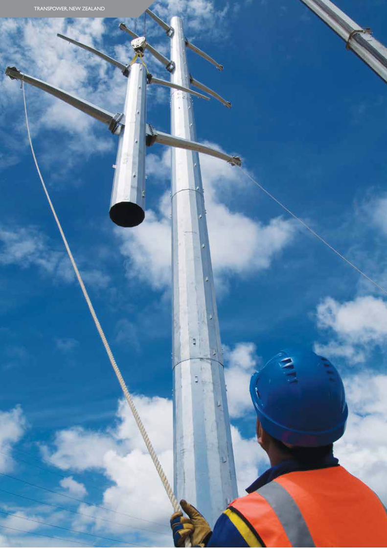
transPOwer, new ZeaLand
UTILITy POLES | Page 11
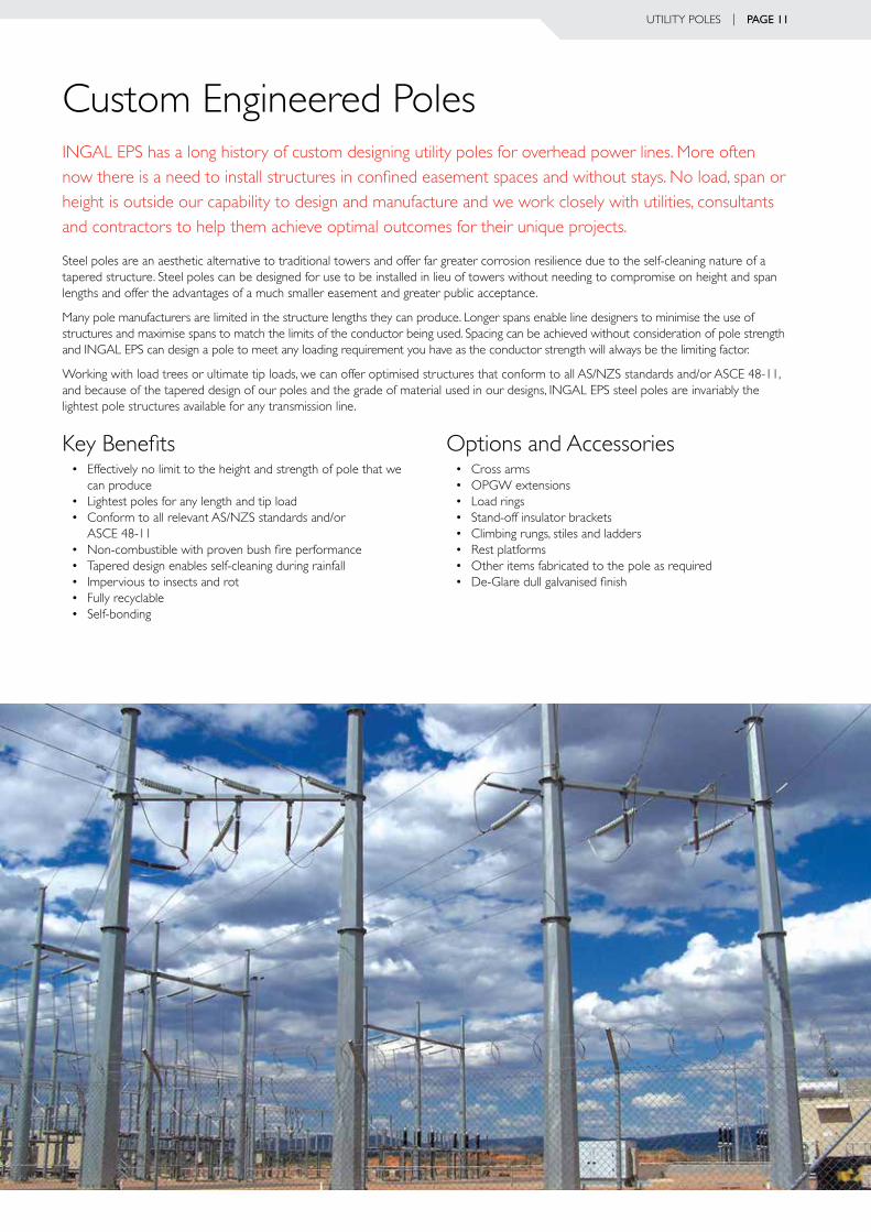
Custom Engineered PolesINGAL EPS has a long history of custom designing utility poles for overhead power lines. More often now there is a need to install structures in confined easement spaces and without stays. No load, span or height is outside our capability to design and manufacture and we work closely with utilities, consultants and contractors to help them achieve optimal outcomes for their unique projects.
Steel poles are an aesthetic alternative to traditional towers and offer far greater corrosion resilience due to the self-cleaning nature of a tapered structure. Steel poles can be designed for use to be installed in lieu of towers without needing to compromise on height and span lengths and offer the advantages of a much smaller easement and greater public acceptance.
Many pole manufacturers are limited in the structure lengths they can produce. Longer spans enable line designers to minimise the use of structures and maximise spans to match the limits of the conductor being used. Spacing can be achieved without consideration of pole strength and INGAL EPS can design a pole to meet any loading requirement you have as the conductor strength will always be the limiting factor.
Working with load trees or ultimate tip loads, we can offer optimised structures that conform to all AS/NZS standards and/or ASCE 48-11, and because of the tapered design of our poles and the grade of material used in our designs, INGAL EPS steel poles are invariably the lightest pole structures available for any transmission line.
Key Benefits• Effectively no limit to the height and strength of pole that we
can produce• Lightest poles for any length and tip load• Conform to all relevant AS/NZS standards and/or
ASCE 48-11• Non-combustible with proven bush fire performance• Tapered design enables self-cleaning during rainfall• Impervious to insects and rot• Fully recyclable• Self-bonding
Options and Accessories• Cross arms• OPGW extensions• Load rings• Stand-off insulator brackets• Climbing rungs, stiles and ladders• Rest platforms• Other items fabricated to the pole as required• De-Glare dull galvanised finish

marLBOrOugh Lines, new ZeaLand


western POwer, austraLia

Bass Link, austraLia
