v-6s0 cvcc - auburn university · pdf fileaws c5.5 -"recommended practices for gas...
TRANSCRIPT

F-15-100-BMarch,1995
INSTRUCTION MANUAL
V-6S0 cvccWELDING POWER SOURCE
..------~IO
••
This manual provides installation and operation instructions for the following V·SSO power sources:
PIN 33324 - 230/460/575 V ac, 60 HzPIN 33325·220/380/415 V ac, 50 Hz
NOTE: This manual is suitable for use with the L-TEC 650 cvcc. It is also suitable for use with the ESAB Phase Arc 11650made prior to April 1, 1995.
These INSTRUCTIONS are for experienced operators. If you are not fully familiar with the principles of operation andsafe practicesforelectricwelding equipment, we urge you to read ourbooklet, "Precautionsand SafePractices for ArcWelding, Cutting, and Gouging," Form 52-529. Do NOT permit untrained persons to install, operate, or maintain thisequipment. Do NOT attempt to install or operate this equipment until you have read and fully understand theseInstructions. If you do not fully understand these instructions, contact your supplier for further information. Be sureto read the Safety Precautions before installing or operating this equipment.
oBe sure this information reaches the operator.
You can get extra copies through your supplier.
~
ESAB~
ESAB Welding &Cutting Products

USER RESPONSIBILITY
This equipment will perform in conformity with the description thereof contained in this manual and accompanyinglabels and/or inserts when installed, operated. maintained and repaired in accordance with the instructionsprovided. This equipment must be checked periodically. Defective equipment should not be used. Parts that arebroken, missing, worn, distorted or contaminated should be replaced immediately. Should such repair or replacement become necessary, the manufacturer recommends that a telephone or written request for service advice bemade to the Authorized Distributor from whom purchased.
This equipment or any of its parts should not be altered without the prior written approval of the manufacturer.The user of this equipment shall have the sale responsibility for any malfunction which results from improper use,faulty maintenance, damage, improper repair or alteration by anyone other than the manufacturer or a servicefacility designated by the manufacturer.
TABLE OF CONTENTS
\/
SECTIONPARAGRAPH
TITLE PAGE
SECTION 11.11.21.31.3.11.3.21.3.31.41.4.11.4.21.5
SECTION'22.12.22.32.42.52.5.12.5.22.5.3
SECTION 33.13.1.13.1.23.1.33.1.43.1.53.1.63.1.73.23.2.13.2.23.2.3
SECTION 44.14.24.3
SECTIONS5.1
SECTION 66.1
6.2
2
DESCRIPTION 5General 5ReceivingwHandling 5Description 5Available Models _......................................................... 5Power Source _................................................................................................... 6Volt-Ampere Characteristics 6Optional Accessories 6HC-38 Remote Voltage and Contactor Pendant Control _....................................................... 6TR-22 Truck Kit 6Safety 6
INSTALLATION 7Location 7Receiving, Unpacking and Placement 7Primary (Input) Electrical Connection................................................ 7Secondary (Output) Welding Connections 8Power SourcelWire Feeder/Control Interconnections _ ---....... 9Digital Control............................ 9Remote Voltage and Contactor Control 9Auxiliary 115 Vac Receptacle : ':................................ 9
OPERATION 11Controls 11Power Switch (ON-OFF) 11Contaetor Control Switch 11Local/Remote Switch 11Voltage Control 11
. Process Switch (cvcc) 12OverTemperature Indicator 12Voltmeter and Ammeter 12Sequence of Operation 12General Procedures for cv Mig/Sub Arc and cc-Stick 12Specific procedures for cv-Mig and Sub Arc :........ 12Specific Procedures for Stick Welding and Arc Gouging........ 12 .
MAINTENANCE 14Cleaning _.._._.................................................................................................................... 14Lubrication.......... 14Testing and Replacing Bridge Assembly Components 14
TROUBLESHOOTING 15TroubleshootingGuide ;.................................................................................................................. 15
REPLACEMENT PARTS 28General _ : : ; : ' ;..... . 28"'-Ordering : :•.> :: ••••~ : -... 28

SAFETY PRECAUTIONS
WARNING: These Safety Precautions are forA your protection. They summarize precautionA ary information trom the references listed in
Additional Safety Information section. Beforeperforming any installation or operating procedures, be sureto read and follow the safety precautions listed below as wellas all other manuals, material safety data sheets, labels, etc.Failure to observe Safety Precautions can result in injury ordeath.
PROTECT YOURSELF AND OTHERS -
~- Some welding, cutting, and gouging
/. . processes are noisy and require ear~ protection. The arc, like the sun, emits
ultraviolet (UV) and other radiationand can injure skin and eyes. Hot metal can causeburns. Training in the proper use of the processes andequipment is essential to prevent accidents. Therefore:
1. Always wear safety glasses with side shields in any workarea, even if welding helmets, face shields, and gogglesare also required.
2. Use a face shield fitted with the correct filter and coverplates to protect your eyes, face, neck, and ears fromsparks and rays of the arc when operating or observingoperations. WARN bystanders not to watch the arc andnot to expose themselves to the rays of the electric-arcor hot metal.
3. Wear flameproof gauntlet type gloves, heavy long-sleeveshirt, cuffless trousers, high-topped shoes, and a weldinghelmet or cap for hair protection, to protect against arcrays and hot sparks or hot metal. A flameproof apron mayalso be desirable as protection against radiated heat andsparks.
4. Hot sparks or metal can lodge in rolled up sleeves,trouser cuffs, or pockets. Sleeves and collars should bekept buttoned, and open pockets eliminated from thefront of clothing
5. Protect other personnel from arc rays and hot sparks witha suitable non-flammable partition or curtains.
6. Use goggles over safety glasses when chipping slag orgrinding. Chipped slag may be hot and can fly far.Bystandersshould also weargoggles over safetyglasses.
WFIRES AND EXPLOSIONS -- Heat fromflames and arcs can start fires. Hot
" slag or sparks can also cause fires andexplosions. Therefore.:
1. Remove all combustible materials well away from thework area or cover the materials with a protective nonflammable covering. Combustible materials includewood,cloth, sawdust, liquid and gas fuels, solvents, paints andcoatings, paper, etc.
2. Hot sparks or hot metal can fall through cracks orcrevices in floors or wall openings and cause a hiddensmoldering fire or fires on the floor below. Make certainthat such openings are protected from hot sparks andmetal.
3. Do not weld, cut or perform other hot work until theworkpiece has been completely cleaned so that there areno substances on the workpiece which might produceflammable or toxic vapors. Do not do hot work on closedcontainers. They may explode.
4. Have fire extinguishing equipment handy for instant use,such as a garden hose, water pail, sand bucket, orportable fire extinguisher. Be sure you are trained in itsuse.
5. Do not use equipment beyond its ratings. For example,overloaded welding cable can overheat and cr.eate a firehazard.
6. After completing operations, inspect the work area tomake certain there are no hot sparks or hot metal whichcould cause a later fire. Use fire watchers when necessary.
7. For additional information, refer to NFPA Standard 51 B,"Fire Prevention in Use of Cutting and Welding Pro k
cesses," available from the National Fire ProtectionAssociation, Batterymarch Park, Quincy, MA 02269.
ELECTRICAL SHOCK .- Contact can
~cause severe injury or death. DO NOTuse AC output in damp areas, if move
~ ment is confined, or if danger of fallingexists. Put on dry, hole-free glovesbefore turning on the power. Also:
1. Be sure the power source frame (chassis) is connectedto the ground system of the input power.
2. Connect the workpiece to a good electrical ground.3. Connect the work cable to the workpiece. A poor or
missing connection can expose the operator or others toa fatal shock.
4. Use well-maintained equipment. Replace worn or damaged cables.
5. Keep everything dry, including clothing, work area, cables,torch/electrode holder and power source. Fix water leaksimmediately.
6. Make sure that you are well insulated, especially whenstanding on metal or working in tight quarters or in a damparea. Wear rubber-soled shoes and stand on a dry boardor insulating platform.
7. Turn off the power before removing your gloves.8. Refer to ANSI/ASC Standard Z49.1 (see listing below) for
specific grounding recommendations. Do not mistakethe work lead for a ground cable.
ELECTRIC AND MAGNETIC FIELDS -
•
May be dangerous. Electric currentflowing through any conductor causes
~plocalized Electric and Magnetic Fields
~ (EMF). Welding and cutting current cre-~l\\l ales EMF around welding cables and
welding machines. Therefore:
1. Welders having pacemakers should consult their physician before welding. EMF may interfere with some pacemakers.
-2. Exposure to EMF may have other health effects whichare unknown.
3. Welders should use the following procedures to minimizeexposure to EMF:A. Route the electrode and work cables together. Secure
them with tape when possible.B. Never coil the torch or work cable around your body.C. Do not place your body between the torch and work
cables. Route cables on the same side of your body... 3

AEQUIPMENT MAINTENANCE •• Faulty orimproperly maintainedequipmentcan causeinjury or death. Therefore:
Used to call attention to potential hazards which could result in personal injuryor loss of life.
This symbol appearing throughout this manualmeans Attention! Be Alert! Your safety isinvolved.
Used to call attention to immediate hazards which. if not avoided, will result inimmediate, serious personal injury orloss of life.
1. Always have qualified personnel perform the installation,troubleshooting, and maintenance work. Do not performany electrical work unless you are qualified to performsuch work.
2. Before performing any maintenance work inside a powersource, disconnect the power source from the incomingelectrical power.
3. Maintain cables. grounding wire, connections, powercord, and power supply in safe working order. Do notoperate any equipment in faulty condition.
4. Do not abuse any equipment or accessories. Keepequipment away from heat sources such as furnaces,wet conditions such as water puddles, oil or grease,corrosive atmospheres and inclement weather.
5. Keep all safety devices and cabinet covers in position andin good repair.
6. Use equipment only for its intended purpose. Do notmodify it in any manner.
ADDITIONAL SAFETY INFORMATION -- Formore information on safe practices for electric arc welding and cutting equipment, askyour supplier for a copy of "Precautionsand Safe Practices for Arc Welding, Cuttingand Gouging," Form 52-529.
The following publications, which are available from theAmerican Welding Society, 550 N.W. LeJuene Road, Miami, Fl 33126, are recommended to you:1. ANSI/ASC 2:49.1 - "Safety in Welding and Cutting"2. AWS C5.1 - "Recommended Practices for Plasma Arc
Welding"3. AWS C5.2 - "Recommended Practices for Plasma Arc
Cutting"4. AWS C5.3 - "Recommended Practices for Air Carbon Arc
Gouging and Cutting"5. AWS C5.5 - "Recommended Practices for Gas Tungsten
Arc Welding"6. AWS C5.6 - "Recommended Practices for Gas Metal Arc
Welding"7. AWS SP - "Safe Practices" - Reprint, Welding Handbook.8. ANSIIAWS F4.1, "Recommended Safe Practices for
Welding and Cutting of Containers That Have HeldHazardous Substances."
The following definitions apply to DANGER, WARNING,CAUTION found throughout this manual:
AI!!!!iim Used to call attention to hazards whichcould result in minor personal injury.
FUMES AND GASES -- Fumes andgases, can cause discomfort or harm,particularly in confined spaces. Donot breathe fumes and gases. Shielding gases can cause asphyxiation.Therefore:
CYLINDER HANDLING -- Cylinders, ifmishandled, can rupture and violentlyrelease gas. Sudden rupture of cylinder, valve, or relief device can injure orkill. Therefore:
D. Connect the work cable to the workpiece as close aspossible to the area being welded.
E. Keep welding power source and cables as far awayfrom your body as possible.
1. Always provide adequate ventilation in the work area bynatural or mechanical means. Do not weld, cut, or gougeon materials such as galvanized steel, stainless steel,copper, zinc, lead, beryllium, or cadmium unless positivemechanical ventilation is provided. Do not breathe fumesfrom these materials.
2. Do not operate near degreasing and spraying operations. The heat or arc rays can react with chlorinatedhydrocarbon vapors to form phosgene, a highly toxicgas. and other irritant gases.
3. If you develop momentary eye, nose, or throat irritationwhile operating, this is an indication that ventilation is notadequate. Stop work and take necessary steps to improve ventilation in the work area. Do not continue tooperate if physical discomfort persists.
4. Referto ANSI/ASC Standard Z49.1 (see listing below) forspecific ventilation recommendations.
1. Use the proper gas for the process and use the properpressure reducing regulator designed to operate fromthe compressed gas cylinder. Do not use adaptors.Maintain hoses and fittings in good condition. Followmanufacturer's operating instructions for mounting regulator to a compressed gas cylinder.
2. Always secure cylinders in an upright position by chain orstrap to suitable hand trucks, undercarriages. benches,walls. post, or racks. Never secure cylinders to worktables or fixtures where they may become part of anelectrical circuit.
3. When not in use. keep cylinder valves cldsed. Have valveprotection cap in place if regulator is not connected.Secure and move cylinders by using suitable hand trucks.Avoid rough handling of cylinders.
4. Locate cylinders away from heat, sparks. and flames.Never strike an arc on a cylinder.
5. For additional information, refer to eGA Standard P-1,"Precautions for Safe Handling of Compressed Gases inCylinders." which is available from. Compressed GasAssociation. 1235 Jefferson Davis Highway, Arlington.VA 22202.
iii;
4

SECTION 1
1.1 GENERAL
This manual has been prepared or use by an experienced operator. It provides information to familiarizethe operator with the design, installation and operationof this equipment. DO NOT attempt to install oroperate this equipment until you have read and fullyunderstood these instructions. The information presented here should be given careful consideration toensure optimum performance of this equipment.
1.2 RECEIVING-HANDLING
Upon receipt, remove all packing material and carefullyinspect for any damage that may have occurred duringshipment. Any claims for loss or damage that mayhave occurred in transit must be filed by the purchaserwith the carrier. A copy of the bill of lading and freightbill will be furnished by the carrier on request.
DESCRIPTION
When requesting information concerning this equipment, it is essential that Stock, Serial and Modelnumbers of the equipment be supplied.
1.3 DESCRIPTION
The V-6S0 is designed for Mig short arc, spray arc andflux core welding, as well as submerged arc applications.
1.3.1 AVAILABLE MODELS
V-650 230/460/575,60 Hz, 3 phase, PIN 33324V-650 220/380/415,50 Hz, 3 phase, PIN 33325
Table 2-1. Specifications
Rated Output 1000/0 Duty Cycle 650 Amp @ 44 V dc
Output Voltagel CV Mode 13 V dc Min - 44 V dc Max @ 650 AmpsCurrent @ RatedInput Voltage CC Mode 50 Amps @ 20 V dc thru 650 Amps @ 44 V dc
Open-Circuit CV Mode Adjustable V de
Voltage CC Mode 65 to 66 V dc
Input Voltage230/460/575 V ac, 3-Ph., 60 Hz220/380/415 V ac, 3-Ph., 50 Hz
230 Vac 8 Amps No Load; 108 Amps Full Load
60 Hz 460 Vac 4 Amps No Load; 54 Amps Full Load
Input Current 575 Vac 3 Amps No Load; 43 Amps Full Load
@ Rated Load 220 Vac 8 Amps No Load; 113 Amps Full Load
50Hz 380 Vac 5 Amps No Load; 65 Amps Full load
415 Vac 4 Amps No Load; 650 Amps Full Load
Power Factor @ Rated Load , 83%
Efficiency 830/0
Width 21.6" (550 mm)
Dimensions Depth 33" (838 m)
Height 31" (787 mm)
Approx. Net Weight 670 Ibs (304 kg)
. V-G50 cvcc Power Source5

--.----.-------------------- ---- _.._..--_._-----::_--:..=-.=-.:::=-~--=--=._=---==-----=-."._=,,=..._---=-=---=-=--="""""""""""""""'''''''''''''''''''''''''''''''~'''"'''''''''''-------------I
SECTION 1 DESCRIPTION
1.4.2 TR-22 TRUCK KIT, PIN 33650
closure switch to close the contactor making the outputterminal "hot" at all times for arc gouging. The locaV t:remote switch on the front panel must be placed in theremote position when using this accessory.
I--to--
i\ 1\ " t--t-- '--
\ , 1\ 1\ 1\
1\ MIN. \ \ \ \ MAX., 1\ \ \ \1\ \ ,
""' ..........~ ..........,
.......... ""- r-..Io- .......1"'---- ""- r-- io--
1.3.2 POWER SOURCE
The power source is a constant potential, silicon controlled rectifier (SCR), three-phase, star-connectedtransformer/rectifier type dc unit with solid statecontactor and control circuitry. It provides the voltampere curve characteristics desired for Mig and submerged arc welding in the cv mode or stickwelding andarc gouging in the cc mode.
The power source is equipped with an on demandcontrolled fan. It helps to minimize the amount of dirt,spatter and dust deposited in the power source as aresult of a continuously running cooling fari. It consistsof two relays which allows the fan to run only when thesolid state contactor is closed to provide cooling to theinternal magnetics and components.
NOTE: As shipped, this feature is disabled. To activatethe thermal fan control circuit, remove the left sidepanel. Locate relay K4 on the rear left transformermounting support. Move the white wire from terminal1 to terminal 5. When activated, it is normal for thecabinet sheet metal to be hot to the touch when in theidle mode (fan not running). When required, the fan willautomatically energize and cool the internal components as well as the cabinet sheet metal.
70
60
50
4D
so
iii~ 10o~w(!)
~o>I-~ 70l-
5 60
g 50
4()
30
20
10
IMAX._ -
MIN. I--T
tOO 200 300 4<l0 500 600 700
D.C. OUTPUT CURRENT (MIPS)
CV MODE FOR MIGISUB AAC
100 200 300 400 500 600 700 600
D.C. OUTPUT CURRENT (AMPS)
CC MODE FOR STICK/ARC GOUGINGISUB ARC
Figure 1-1. Volt-Ampere Curves
1.3.3 VOLT·AMPERE CHARACTERISTICS
The curves shown in Figure 1-1 represent the fixedvolt-ampere static characteristic for the power source.The slant of these curves is referred to as the 'slope"and is generally defined as the 'voltage drop per 100amperes of current rise." These curves show theoutput voltage available at any given output current forthe minimum and maximum settings of the voltagecontrol. Values for other settings will fall between theminimum and maximum curves. In the cv mode, it ispossible to select welding conditions by approximatingthe open circuit voltage required for a particular loadcurrent.
1.4 OPTIONAL ACCESSORIES
1.4.1 HC-3B REMOTE VOLTAGE ANDCONTACTOR PENDANT CONTROL(PIN 33838)
This accessory operates in parallel with the powersupply's voltage control potentiometer to provide fullrange remote output control and provides a contactor
V-GSO cvcc Power Source
6
This accessory provides for complete mobility of thepower source. The kit consists of front castors, reartwo cylinder rack and wheels, gas cylinder bracket, andhandle.
1.5 SAFETY
Before the equipment is put into operation, the safetysection at the front of this manual should be readcompletely. This will help avoid possible injury due tomisuse or improper welding applications. The definitions relating to the DANGER, WARNING, and CAUTION safety notations are described at the end of theSafety Section in the front of this manual-read themand their specific text references carefully.
1\./~

•SECTION 2
2.1 LOCATION
A proper installation site is necessary for the unit toprovide dependable service. This means the powersource should be placed in a way that provides freedom of air movement through the unit while minimizingexposure to dust. dirt, moisture, and corrosive vapors.A minimum of 18 inches (46 em) is required betweenthe side and rear panels of the power source and thenearest obstruction.
INSTALLATION
C. Check air passages at front and rear of cabinet, making sure that no packing materials thatmay obstruct airflowthrough the powersource.
D. After selecting an installation site (see paragraph 2.1), place the power source in thedesired location. The unit may be lifted eitherby using the lifting ring or by forklift truck. If aforklift is used for lifting the unit, be sure thatthe lift forks are long enough to extend completely under the base.
2.3 PRIMARY (INPUT) ELECTRICALCONNECTION
This power source is a three-phase unit and must beconnected to a three-phase power supply. It is recommended that the unit be operated on a dedicated circuitto prevent impairment of performance due to an overloaded circuit.
CAUTION
WARNING
Do not use filters on this unit as they would restrictthe volume of intake air. Output ratings on this unitare based on an unobstructed supply of coolingair drawn over its internal components. Warrantyis void if any type of filtering device is used.
Figure 2-1. Dimensions
The selected site should also allow easy removal oHhepower souFce outer enclosure for maintenance. SeeFigure 2-1 for overall dimensions of the unit.
•
•
2.2 RECEIVING, UNPACKING ANDPLACEMENT
A. Immediately upon receipt of the power source,inspect for damage which may have occurredin transit. Notify the carrier of any defects ordamage.
B. Removethe power source from the container.Remove all packing materials. Check thecontainer for any loose parts.
ELECTRIC SHOCK CAN KILLI Before making electrical input connections to the power source, "Machinery Lockout Procedures" should be employed.If the connections are to be made from a linedisconnect switch, place the switch in the offposition and padlock it to prevent inadvertenttripping .If the connection is made from a fusebox,remove the corresponding fuses and padlock thebox cover. If it is not possible to use padlocks,
.attach a red tag to the line disconnect switch (orfuse box) warning others that the circuit is beingworked on.
A. The primary power leads should be insulatedcopper conductors. Three power leads andone ground wire are required. Either rubber
V·650 cvcc Power Source7

SECTION 2
covered cable orconduit (flexible or solid) maybe used. Table 2-1 provides recommendedinput conductors and line fuse sizes.
B. Open the access door on the right side of themachine. Identify primary power input connections on the inputterminal board, customerground connection to chassis ground lug, andprimary voltage-changeover terminal board.Refer to Figures 2·2 and 2-3.
Table 2-1. Recommended Sizes for InputConductors and Line Fuse
Rated Input Input &GND Fuse Size
Volts Amps Conductor AmpsCUlAWG
230 108 No.2 175460 54 NO.6 90575 43 No.8 75
INSTALLATION
E. The primary voltage-changeover input termi- •nal board (Figure 2-2) illustrates the primaryvoltage link connections. The voltage links onthis board are factory set for highest voltageoperation and must be reset for the requiredservice voltage. Figure 2-2 shows the requiredconnections to reestablish the desired servicevoltage. The voltage links are set up byreconfiguring the copper link bars to the silkscreened voltage designations forthe desiredvoltage.
2.4 SECONDARY (OUTPUT) WELDINGCONNECTIONS
WARNING
Before making any connections to the powersource output terminals, make sure that all primary input power to the machine is off.
,r;
*Sized per National Code for 80 °Crated copper conductors@ 30 °Cambient. Not more than threeconductors in raceway orcable. Localcodes should be followed if they specify sizes other than those listedabove.
C. Thread the input and ground cable(s) throughthe large strain-relief hole in the rear panel ofthe power source. Connect the primary powerleads to terminals L1, L2, and L3 on the inputterminal board. Secure the strain relief on theinput cable. Connect the ground wire to theterminal lug, which is located directly belowthe input terminal board on the chassis baseinside the cabinet. o o
•
i.
i I
!; j
WARNING
The" chassis must be connected to an approvedelectrical ground. Failure to do so may result insevere electrical shock, causing severe burns ordeath.
D. Recheck all connections for proper tightness.Ensure all connections are correct and wellinsulated.
V-GSO cvcc Power Source
8
Figure 2-2. Voltage Changeover Input TerminalBoard (230/460/575 V illustrated)
The output connections are located on the front panel(Figure 2-3). The negative connection is located at thebottom right corner and the positive (high inductanceand low inductance) connections are located at thebottom left corner. Two output terminals are providedfor each output connection. Each terminal is rated fora maximum output current of 400 amps. When operating in excess of 400 amps, parallel cables must beused, one in each output terminal. Table 2-2 providesthe recommended cable sizes.

SECTION 2
2.5 POWER SOURCE/WIRE FEEDER/CONTROL INTERCONNECTIONS
Refer to Figure 2-3.
2.5.1 DIGITAL CONTROL
Digital wire feeder control connections are provided bya 19-pin amphenol connector (J1) located on the rearpanel of the power source in the upper right-handcorner.
2.5.2 REMOTE VOLTAGE ANDCONTACTOR CONTROL
This function is provided by an a-pin amphenol connector (J2) located on the rear panel directly belowconnector J1. It receives a mating plug from a Hand ControlAssembly (optional). This receptacle is operative onlyif the Local/Remote switch on the power source frontpanel is in the t1Remotell position.
V-650 cvcc Power Source·
~1"" ,
INSTALLATION
2.5.3 AUXILIARY 115 V AC RECEPTACLE
Ten amperes of 115 V ac power can be supplied toexternal accessories by connecting them to receptacleJ3 on the rear panel directly above the fuses.
Table 2-2. Secondary Cable Sizes
Total Length (Feet) ofWelding Cable in Weld Circuit*Current
50 100 150 200 250
100 6 4 3 2 1/0
150 4 3 1 1/0 2/0
200 3 1 1/0 210 3/0
250 2 1/0 210 3/0 4/0
300 1 210 3/0 4/0 4/0
400 210 3/0 4/0 4/0 2~210
500 3/0 3/0 4/0 2-210 -2-3/0
600 2-210 2-210 2-210 2-3/0 2-4/0
700 2-3/0 2-3/0 2·3/0 2-4/0 2-4/0
*Total cable length includes work and electrode cables. Cable size isbased on direct current, insulated copper conductors, 1DO-percentduty cycle and a voltage drop of 4 or less volts. The welding cableinsulator must have a voltage rating that is high enough to withstand
- the open circuit voltage of the machine.
9

;.
SECTION 2
POS. LOW INDUCTORTORCH WIRE FEEDER
CABLE
POS. HIGH INDUCTORTORCH WIRE FEEDER
CABLE
NEG. WORKPIECECABLE CONNECTOR
J2 14 PIN(OPTIONAL REMOTE
VOLTAGE & CONTACTORCONTROL) 2.5.2
J1(DIGITAL WIRE FEEDER
CONNECTOR) 2.5.1
J3(115 V ac AUXILIARY)
2.5.3
INSTALLATION
GROUND
VOLTAGE CHANGEOVERTERMINAL BOARD (TB1)
ACCESS DOOR
IIlJIIlJ
~\
Figure 2-3. Interconnection Diagram
V-G50 cvcc Power Source
10

SECTION 3 OPERATION
CAUTION
Never, underany circumstances, operatethe powersource with the cover removed. In addition to thesafety hazards, which are considerable, impropercooling may cause damage to the components.Keep side panels closed when unit is energized.Welding helmet, gloves, and other personal protection should always be worn when welding.
3.1.2 CONTACTOR CONTROL SWITCH
The Contactor Control switch is located on the frontpanel of the power source. In the closed position, thesolid state contactor is energized from the powersource and the output terminals are electrically hot. Inthe Remote position, the solid state contactor is energized from a remote location, such as a wire feeder.The closed position allows presetting an approximatewelding condition without actually striking an arc. Theremote position allows the solid state contactor and theconstant voltage output to be controlled from a remotemig wire feeder or mechanized sub arc control.
•
3.1 CONTROLS (See Figure 3-1)
3.1.1 POWER SWITCH (ON-OFF)
The power switch is located on the front panel of thepower source. In the "off" position, the unit is essentially shut down. With the switch in the "off" position,power is still present at the main contactor and at theswitch itself. To fUlly shut down the power source,power must be disconnected at the line disconnectswitch or the fuse box, depending upon the installation.
With the switch in the "on" position, 115 V ac power isproVided to energize the main contactor coil, closingthe main contactor which provides input power to themain transformer and the low voltage control circuitry.
3.1.3 LOCAL/R.EMOTE SWITCH
With this switch in the Local position, output is controlled by setting the voltage potentiometer on the frontpanel to the output desired. In the Remote position,output is controlled using the optional Remote VoltageControl Assembly via connector J2.
3.1.4 VOLTAGE CONTROL
This control allows the operatorto regulate the requiredamount of welding voltage. Placing the Local/Remoteswitch in the Remote position disables the voltagecontrol.
3.1.4
3.1.5
V 650cVCC
IliBI'O 0 ~~~-)... ) ~~§ 0o~o ~=:::;;:;;-=
Figure 3-1. Control Locations
3.1.3
•V-6S0 cvcc Power Source
11
---------------_._------------_.__.....

SECTION 3
3.1.5 PROCESS SWITCH (cvcc)
The process switch allows for selecting either a "Flat"volt-amp characteristic (cv) or a "Drooping" characteristic (cc).
3.1.6 OVER TEMPERATURE INDICATOR
This indicator will light when an internal overheatingcondition has occurred and oneof the thermal switcheshas opened, causing the power source to shut down toprotect critical components.
3.1.7 VOLTMETER AND AMMETER
Avoltmeter (O-60V) and ammeter (O-SOOA) provide anaccurate indication of dc open circuit and weldingvoltage, and welding current.
OPERATION
C. Set the on-off switch to the on position.
D. To preset the approximate welding voltage,place the contactor switch to the "closed" (on)position. This action will energize the powersource on output terminals, allowing the desired voltage condition to be preset using theVoltage Control potentiometer and observingthe voltmeter.
E. After setting the desired voltage condition,place the contactor switch to "Remote". Thismode requires a remote startcontrol activationin order to start the welding sequence.
F. Commence welding. Observe the voltmeter,ammeter, and the weld. Readjust the voltage,inductance, and wire feed speed settings asnecessary to obtain a satisfactory weld.
•
! 'i '.,
j
3.2 SEQUENCE OF OPERATION
Prior to performing the steps below, open the walldisconnect switch or remove fuse from fuse box toelectrically isolate the power source.
3.2.1 GENERAL PROCEDURES FOR CVMIG/SUB ARC AND CC-STICK
A. Make the secondary output connections to thepositive and negative output terminals.
B. Make the control connections. Refer to theappropriate wire feeder, mechanized control,and/or torch instruction booklets for additionalprocess requirements or control connections.
C. If primary power connections have been madeto the main contactor, and the voltagechangeover terminal board and control transfOrmer jumpers properly match the incomingvoltage, close the main wall disconnect switchor reinstall fuses in fuse box.
3.2.2 SPECIFIC PROCEDURES FOR CVMIG AND SUB ARC
A. Set the local/remote switch to the desiredsetting.
B. Set the process switch to the cv position.
V·650 cvcc Power Source
12
G. When welding is completed. release torchswitch at the remote location. (This action willdeenergize the power source solid statecontactor and remove dc power from the output terminals.)
If the welding operation terminates prematurely. check Ii.\the front panel overheat light. If the light is on, internal ~.overtemperature conditions have caused the thermalswitches to open, deenergizing the solid state contactor.When the unit has sufficiently cooled, these switcheswill reset, the overheat light will go out, and weldingmay resume.
3.2.3 SPECIFIC PROCEDURES FOR STICKWELDING AND ARC GOUGING
A. Place the Remote Control toggle switch intoPANEL position if output current is regulatedfrom the Voltage/Current Potentiometer onthe panel, or in REMOTE position if outputcurrent is regulated from the optional HandControl.
B. Set the panel or remote Output Control toprovide the approximate desired welding current (See V-I Curves), and after the output is"hot," fine tune the control to obtain the exactwelding condition.

SECTION 3
C. Set the contactor toggle switch to the "closed"position -- this energizes the main contactor,cooling fan, and the magnetics up to the solidstate contactor.
D. Place the Process Control toggle switch in theCCF-STICK (ARC GOUGING) position. Thiswill energize the solid-state contactor and allassociated circuitry up to the output terminals.
E. Commence welding by touch or scratch start~
ing.
V-GSO cvcc Power Source
OPERATION
13

i;
: I
::"
,, ;
j
I
SECTION 4
If this equipment does not operate properly, stop workimmediately and investigate the cause of the malfunction. Maintenance work must be performed by anexperienced person, and electrical work by a trainedelectrician. Do not permit untrained persons to inspect,clean, or repair this equipment. Use only recommended replacement parts.
WARNING
Be sure that the wall disconnect switch or circuitbreaker is open before attempting any inspectionor work on the inside of the power source.
4.1 CLEANING
Since there are no moving parts (other than the fan) inthe Power Source, maintenance consists mainly ofkeeping the interior of the cabinet clean. Periodically,remove the cover from the cabinet and blow accumulated dust and dirt from the airpassages and the interiorcomponents using clean low pressure air. It is imperative that the air passages, to the interior of the PowerSource, be kept free of dirt accumulation to ensureadequate circulation of cooling air, especially over therectifier bridge plates. The length of time betweencleaning will depend on the location of the PowerSource and the amount of dust in the atmosphere.
4.2 LUBRICATION
Fan motors with oil tubes located on the side of themotor require lubrication after 1year of service. Motorswithout oil tubes are permanently lubricated for life andshould not require any attention.
4.3 TESTING AND REPLACING BRIDGEASSEMBLY COMPONENTS
SCRs are devices which allow current to flow in onlyone direction and block current in the other direction.The SCRs used in this Power Source are designed toprovide long trouble-free operation; however, should afailure occur, they may require replacement. Thelocation and replacement parts data for the SCRs areshown in Figures 6-4 and 6-5.
V-650 cvcc Power Source'
14
MAINTENANCE
A. Remove the top cover and both side panels. •B. Testing SCRs.
1. Having removed the top and side panels ofthe Power Source, locate the bridge recti-fier assembly containing the individual'SCRs.
2. Disconnect resistor R1.
3. With ohmmeter on Rx1 scale, place theNEG test probe on the negative outputterminal and the pas probe on eitherpositive outputterminal. The metershouldshow high resistance of 100 ohms orhigher. Typical readings of around 500ohms are common.
4. Reverse probes and note ohmmeter read-ing. Readings should be lower than thosespecified in step 3. These lower readingsaredue to the FreeWheeling Diode (FWD).One or more of the SCRs or FWDs is badif a reading of 0-5 ohms is shown in bothdirections.
5. Using the above testing procedure, you tiD"
can determine if any of the bridge compo-nents are faulty. However, to actuallypinpoint which component is bad, youmust first isolate each component by dis-connecting the transformer secondaryleads from the SCR anode heat sinks andby disconnecting the free wheeling diodepigtail.
CAUTION
When replacing SCRs make sure mounting surfaces are clean. Coat mounting surfaces withalcoa No.2 EJC electrical joint compound, avail·able from ESAB in 8 oz. containers under PIN73585002. Tighten the SCR clamp nuts by handuntil fingertight. Then using a wrench, alternatelytighten each nut 1/4 turn at a time for one completerevolution until the force indicator on the clampreads 1000 pounds.

SECTION 5 TROUBLESHOOTING
(;Jr.'J WARNING
4. Solid-state breaker tripped due to overload.
•
•
Be sure that all 3-phase primary power to thepower source has been externally disconnected.Open wall disconnect switch or circuit breakerbefore attempting inspection or work inside of thepower source.
Check the problem against the symptoms in the followi~g troubleshooting guide. The remedy may be quitesimple. lfthe cause cannot be quickly located, open upt~e Power Source and perform a simple visual inspection of all the components and wiring. Checkfor secureterminal connections, loose or burned wiring or components, or any other sign of damage or discoloration.
5.1 TROUBLESHOOTING GUIDE
A. Power Source Inoperative.1. No input power. Check main line
(customer's) switch fuses -- replace ifopen.
2. Poor or improper input (terminal board)connections.
3. Defective ROS switch on front panel -replace.
4. Main transformeroverheating. Also, checkforproper cooling, properprimary hookup,or shorted turn on secondary.
5. Fan motor not operating -- check motorand leads. Remember, this is normalwhen thermal fan kit is used.
6. Maincontactordefective --checkforproperoperation.
B. No Output -- Fan Running.1. Poor or improper electrical input -- check
input connections on Terminal Board.
2. Poorconnections at outputterminals/workstation -- check, tighten or replace.
3. Power Source overheating -- thermalswitches tripped due to restricted coolingair, let unit cool down. .
V-G50 cvcc Power Source
5. PC board defective or loose PC boardconnector(s) -- if I'oose, reinsert; if defective, replace.
C. Limited Output and Low Open-Circuit Voltage.1. Input voltage jumper links on terminal
board improperly set - check for propervoltage.
2. Poor output connections.
3. Power Source may be single-phasing -check incoming three-phase power.
4. Panel-Remote switch in remote positionand remote voltage pot disabled.
D. Erratic Weld Current.1. Incorrect welding cable size -- use correct
cables.
2. Loose welding cable connection (Will usually get hot) -- tighten all connections.
3. Improper wire feeder setup.
4. Defective SCR in Bridge Assembly --checkand replace per section 2.
5. PC board defective -- replace.
E. High Output, No Voltage Control.PC board defective or loose -- reset and/orreplace board.
F. No 115 Volt ac Output.1. Check secondary of control winding on
main transformer for 115 V ac.
2. Circuit breaker tripped -- reset.
G. Line Fuse Blows When Power Source is FirstPowered Up.
1. Shorted SCR in Bridge Assembly -- checkand replace per section 2.
2. Shorted free wheeling diode{s) -- checkand replace per section 2.
15

V-GSO cvcc Power Source
16
•2 A
2 F
t)j2
K
2L
2N
2N
20
2
2 a
2R
2S
IBLU
OR~
1115-7
TROUBLESHOOTING
VlO
{' 51E1RED inA
2: 2
BlK lOA6
~2
2 M I
6OOohm,l2W ~
!Jl IJ)2iJ
.j C9 L1018,~~ OlB
~
(+1HIGH
C7(.~iJ
ala (+l- LOW
XI
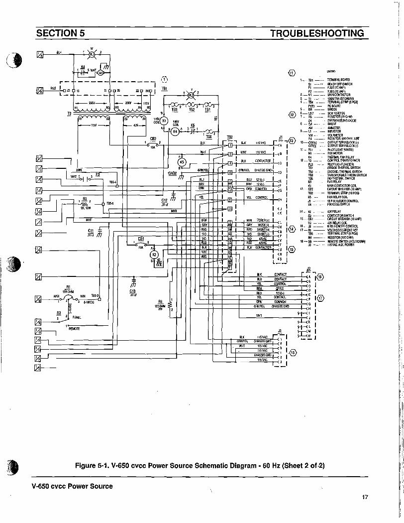
Figure 5-1, V-650 cvcc Power Source Schematic Diagram - 60 Hz (Sheet 1 of 2)
X2
Xl I X,
RED
X2r~;_-lI:1T--tX;al ~;;X2;:;:::;;:;_-XlT--rX,:c__T;:;;:X2~2T;:;::;:::;:_-X311:K. X4 X5r' X$ 'B' I':XYf;v:j:::'-V.x::l.s ~ X4 X5S1 X6 ~ - Q -L
flV IIV IIV IIV IIV 14V I PeBl ~r--t--+---''--t---t---+-t----L----j-+---I---+--:::f=-+-_+..., I IPIll-615296)
'\OJ OR~L< PH I 54 ld- - - - I- - - - - - - - - - '-...l' -L, VEL, P2-8 J 2
I TB4 BQ-J'-f--+---=BL=-tUr WHT 3 CV C, 2 - 3 ,! _ 7 ( P2-7 Pl1S'.: - -rf" - - - -= - - - - - - -I- ~ GRV <P2-3 • "1 2 cc...!-- 2 0
I ~ 1j(3\>--2+-----'------t__-+__~/L__+__+-~8RN:::i!(P2-6 PI" I8 -----v::Y 7 RED (PN ,- - - ~:t---_t--_r_--' 2 E
'::====;-:--:j:::====t.:--=====:-;;~~===i:--======-:;-;;;~::::t::-----:VID=-t< P24 'PI·tO )J:I---_ _+----t---'- :: 1 ~"-"'-+----+---...,.~~~~ ~m~~ ~~ ~~ ~
-;- l:'~ ..- )':." ~. -..,- ).":, I:,&:, i ~~
__~f _!~I_._ _ ~~ J_~~ !!~ I VID '< P2." 'r I K2 ~n ~il GAV (P2·'D : I ,~~L.!- I~of--- - ... OR~ <P2o!!: --. r--
'-- -+-_-;;;8LU~1<P2.12 I REMOTE'- +---.,YEl~[<P2.2 , __ ~\ ~1
RED [<P2-5 .J 2 t~
r ~ Pl.11 +Iev RED CI; TIl5-1
rl ~ i: t i PI4~l--
01 v~vv~.
+----- ---iIooll....I- -+_....;VEL,;;;;....---' i"'"
230/460/575 VOLTS, 3PHASE, 60 Hz, WIEQUIPMENT GND
r------------------,n, It,n-n--r:--nnf-KHS-'--~ Kl·Tl T Kin •T KI·n
,I
SECTION 5
o
SECTION 5 TROUBLESHOOTING
Figure 5-1. V-6S0 cvcc Power Source Schematic Diagram - 60 Hz (Sheet 2 of-2)
I:,]'1;
I:I' ~
"i':i,['I"I'I:;:I!-
ii'I;;, .::
iiI
i !i1
I
!I
I!i
I
1I,i
i!i
17 I)!1i
'<GENIl
, •._ lei _..... TERMINAl BOAACSI -_. READY OFF SWITCHFI -_ FU~(I~AldPI
2 .._ ~~ == lli~~r~TOA3- T1 ..-- MAIN TRANSFORMER4 ..... TB4 _ TERMINAL STRIP 16 PaS)
ptBI _. PC BOAROS...... BA .-.._ BRIDGEL .. LH - SC~ TOROIDS7 .. R5 _- RESISTDRI1ODiiM)
I),,, .. FREEWHE8.ING DIODE8 .... SH -'" .. SHUNT
AM -- AMt.lE'lEA9._ Ll .....- INDUCTOR
VM .. . VOlThlEltRR4 ..._ .. Rl;SISTOR.tiOOOHld.I2W
1O..···0lel.) OUTf'UT TERMBLODK (+1OTB·) OUTPUT TERM BLODK I')
11 _. PLI PllOTLlGHT(WH1TE1IIlI ...._.....- FAN MOTORK4 TIlERMAlFAN AEl.AY
12 ... 12 _..... CONTROL TRANSFORMER
~ . ~l\Pol;~=~m;HTS2 SECOND, THERMAL SWlTCllTS3 lRANSFORMEA THERIl SWITC/lTS6 INO THEIlt.IAl SWITCHK5 FAN RB.AYKl t.lAlN OONTADTOR CDiL
.3 _. CBE CIRCUIT BREAKER (10 AMP)182 ..__. TERMINALSIRIP (IBPOS)K5 ...• fAN RELAYOOllJl -_..- 19 PIN FEBJER OOtflROL54.... -'" PAOCESS5W1TCH
14-..... K2 4lIfRELAY52 ••- CONTADTOR SWITCH
IS-CBI __ C1ACUITBREAKER{IOAMP)K2 -....... ~2VRELAY COIL
18_ J2 __. 6PIN REUDTECOKTlIOL17 - Al -- VOlTAGOCURRENT POT
TllS ... "- TERMINALSIRIP(81'OS)R6 -_... R8lISTOR\IOOOHM)
18 - 53 -- REUDTE SWITCH (VOLTICURR)J3 "-- IISVACAUX.PDWER
WIn
J3
BlK 115VAC r~ IGRWYEl. DliASSIS OND 2 I
WHT 11SVAC 311SVAC 1 1.Ji8\
CHASSISOND 2 I'~11SVAC 3
IlSVCOIL K5~A S:;VI
'-
TBI
lOA
- CB21_2
21,s-----------,
20 22 J 249 I----- ---- -+-'
J
.-AED I 0 ZlL__
WIY,AJ__...;B:::L:.:..K- .......-..<l....-W--{IPL2
,1~SWHTf/h.~
.~
~15KDHM
MAX r;;.. MIN le~
IXJII-----,<,>-' 2 3 o-IOVDC
~53 ~
'2"': PANEL111l11----~
I AEMOTE
~
I'..A.I2T56 TB2 J1
8I.K - r=' 8I.K IISVAC r:::'''®-r ' I I A I
MiT ---- I WHT 115 YAG B 1+----.,:-i---.....:::""-l--f:?!. 2
I C r ~K5 ~ rr I BLU CONTACTOR; C :
~B' %~I I
o BRN GRWV8. r' 'i5' I GRNlVEL CHASSIS GND· 0 I"" BN~~ =1 I
WHY 5 1_3 -=- III...--sLU 1 1I ~ TBS4 rl--'E:".:---t-++-;---t13 BLU 12YI+l E I'-__·'-- +_---eH+ + +-l--'B~RN~l_++_I__f14h--B"'R""N_:"12'_'~~. ."....-I--<F
n:a CAN 'Jt?+- OPl< OOMMON G 1ICJ J A3 C ! r+--t+~-"Vl:,,-L+f-±~I_-[j:6iJ-t1--1~VE:=L'--"'CONlIl=OL"'-i_1-<H I'
,Pn' 1-2 TllS-ti ,O:~ 1/1 .-- 1 ~ • 12K.12W -d:-m 1 I <J I
WIn I I I <K ,
1 II WHI 6RN I BRN roRCH(+} II .---++-H-=G=Ry+-H-i--H9l-T-.J-;:GR"'Y,.--'WQR='=K;;.!.""1-1--( L 1
r-- r---+------+-rH-++H7.::':+'H-+--{]I~H-+-7.':O'--'::':=C!-1HMN1®4Q!.! :I: RED • RED SHUNT.
1 J ,Oluf III r-+---;;::,,-------+-H++-H-+=~O,..,'H+_i_-m7-+---,j...,VI;oO~-"SH,:!UNT~'L..-j.--<p ICBI . '~D VIO 42VAC
L--"Io-:::.-:-:il'-2=--_-+--i-++-H-+REO;;.H-++-t:;l-+~j..-:,;AE:;O.....","'4Z'1~A=C=lf__<~ I.........., lOA ~r-+--1-H-+-1-+,WH~8I.K:;.rH-++-I1 BU< CONTADTDR U I.@
K2 RED I , <R IB ~~ , ~ I l~_1
J "++-1f--~_-_J-H~---:::T.-_.;s=_----J.-<J2I;,(f----------+--H-+---r-----' r :~ =~~ r~l@ffi BH-+-+--4---+-+----:-::~;=.--...;OOImlOL:::C"'PIDC:::;:.:----.--(C I~~~ y-+_t--_---1__---..;RE;;;Dr---_-:d:'!I0'o!V;;+,.-_-+--<~ I
YEL CONTROL F I®L--+-J-+--+------;Gi~:~L--;;DHASS;T,OOId:;;;;;;~ON;:GN""D,---HG I
~ Il-f-< J 1rL<~ I~ld I~!:.J
V-650 cvcc Power Source
. 1 K
.'"~"IVl~
f12lI<2!J
Ii7.I~
1 D
I
I Q
1
f1A-~
()
_ - -----'-~..~_ •.._-_ _,--,-.-_... --_._----,. --
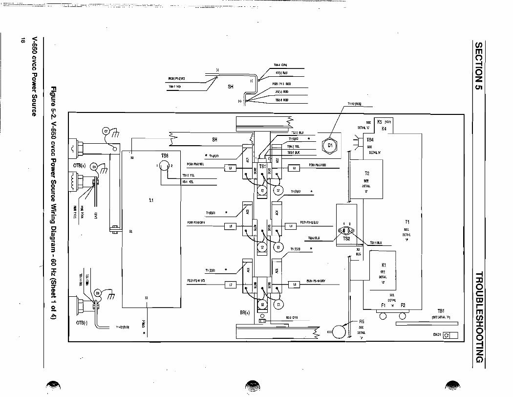
CJ)m(')-46zUI
T2SEE
PETAl'F
ll-X2{BUS)
I 2 T1SEE
PETAl'p
TS1·181.U
XlBUS
K15t'E -4PETAl\. :c'G'
0SEE c:
PETAIL OJFl .~ F2 r-
TB1 miSEEDEIAlL'Fj enRS :J:SEE
0DETAILGNDI [Q[]
'J 0:::!zG)
•
PCBl P20SRED
TS3-2BLU
~CBl P2·10GRV
PCBl P2·12 BI.U
IHCIXS *
TS6,~ VEl SEE
TB5-5 ell( DETAI, '~
1ll,20RHoBR(t)
Tl·ICIXt
PCBI P2·n VIO
TB4-40J;N
...---------J~~~==~~~~TS2.2 BlUT11A)lCl *
_:_B_:P_~:_V1O ~"SH " / ~:~EdJ/_AA1_I'l_RE_D _
('I~TllZ-8RED
XI
Tl·X2(l1USj
SH
TS6 * Tl~Xl
PCBIP2·2'11;~
TSt~ va1l5-1 VE~
t1
~ ~
~:t: ~
Tl19lXl *$! :::i
PCB1PHOI!~
Xl
... <en ,O'lUI0(')
~(')
""0'0
~ "TI... cE'en c0 Cilc... CJ'I(')(I) I
~
~O'lCJ'I0(')
<(')(')
""0'0
~...en0cri(I)
~...:j'(Q
ciii'
(Q...Q)
3O'l0
::I:N-CJ)::::r(I)(I)-....0-.ro.-

CJ)mo-I-ozU1
-f:coctormen::I:oo-;-
I -T56-\ -VEL
5 - K4-A - eLKA - T82·2 - WHTB-T82.' _BLU
K5
- RED-WIlT-BLK-WHT
K4t _181_19
MHA-~
B - T2·Xl
DETAIL 'C'
• - T858 - WHT5 - PC!I~I~ - WHT1-1SH _YEl8-TBl-2 -RED
- BLK- BLU
- RED- BLK
8 -TB5-S9 - T852A - T82·17B - TB2·I!
Kl·L2 RED
Ft·1 R1:D
SEE DETAIL 'B' FOR J1·J2 CONNECTIONS
0 8T65·S BLK T82 J2·A BLK
C82-2 BU< Jl·A BLK
0TBl·) VEL J3.3 WHTKl·A WHT
52·2 BLK KI·A WHT
PL2 Kl·B BLK PCBl T65~ \\1!T ~ JI·B WHTOT8(t) BRNSEE KS·B Btu J!·B BtU
alOETAll'A' ~ S2., BLK JI·C Btu;;;
TIl2·8 VEL j§ ~ TB~I RED J2·e REDJI·H YEL
S3·1 VEL J2-F vEL
RI':! BlU Jl·C VELSH(o)V10 Jt·p VIC
Slit.) RE~ JI·N REO
JI-l BRN1
T85 R6TB5'J DRN 10 JI·M GRV
S3-3 BLUSEE DTBI')YEl
DETAIL I)' " J2.Q DRN
T81i-! RED "J1·G DRN
K3 JI·~ BtUTB;.4SRN I,
TBHBLUS<EIlETAlL T85' BRN
"J!-F BRN.c- Jl· G NlVEl J2·D BAN
T85-2 StU J.\-2 GRNlYEl Jl·DGRNNEl'5
TB2~BLU K3 I T2·1O VIO JIN VIO18
:'.~ (:2~ K2-A RED Jl:T RED1 BlK 17=, = K2·B BlK
TB2·19MlT 3 , Jl·U BLK~5 6'
1854·2 \\1!T
'= J2~ WHT70 08 2 J3 !l! 19Kl·11 BLK ,
K2 K4/K5 20F2·1 BLK
e:=JI 2 3' 1 'i' ~ T2-X2 SRN , 0 0TBI·21 yel =, 5' ~-6'"J = (.-"4 :<: , CB2 CBl, ,
PLl C::::JI!! TB2·' BI.K
F\·2 RBl ~7!
c..g;, c.:s 8 T2·X4 flED
T 8' 'j.J 'T
•.""<I(J)U'I0(")<(")(")
"0:E(!) """I cS'en c0
~cc:; U1
I(!) N
<I(J)U10(")<(")(")
"tI0
~'"I
CJ)0ca(!)
~:::!.::JcoCji)'
co""III)
30'10
:tN-en:::T(!)
~N0-.ClIo-
ZG>

2 TS3T1 X2 ~I
HS * 1$2·' Bl,UTl·)'2 VEL -
II'-- I
HI * I.....-K'·B BLK 9R·ACS
tU * * X,
H8 * * XJBR·AC6
n·Hl RED IC * 'C'n·H3 8lU H2 * * X6t "'"~T2·H40RN \ IV K4-1 RED it X4
F2-2 BLK '~
~ '@ 'G ~TBI-8GRY I f TB4
6DETAIL 'K'
12·H2 VEL BR·ACS* )(1
1.1\·2 !lI.K "r-- Pee1 P2·8 YEl
/@ HI ... BR-AOI '-- 8f'- PCB' fiN BtU
Pll·2 VEl ." XJH6 ."
'--- 1- PCBl P2.J GRY6
T2-H5 BRNCD
.--- 113 * J ~ Tes-:! DRN24 1 3 4 'B'
$HI-lOON 5TBl·18 GRY
- f- H2 * * ~5 - \'-- /' 182·12 OON
K1·T3 ClAY
"0;'--- l- llS *
~I~ PCBl P2-& BRN
* 3r-~ H4 * XS - ~ PCIlI P2·l RED
.--- 2.. X4 - PCBI fiN VlO
Kl·l1 GRY ~I
L1 7 9 10 '1-
TS'·6 GAY IKt:l2 GRY .......... 0
I
'It X6
KI-l2 GRY @ cl> Te'·'4 GRYl2 13 15 r; f- H3 * .. X4
18'·12 GRY - H1 * SA-ACIK'·Tl GAY "@ H$ * * XI
Kl-L3 GRY
~f- H4 * 'A' BR·AC2
1B\·2 GRY... X3
~I- 112 *
0 0 6p 18'/ f- IlS * R~' YEt
)'2
PCB1PHYEt
I f 01 (BllS}
I\) <0 I~U10n<(')(")
."0:e(I) 'TI"""I: cS"C/) c0 nlc"""I:
U1(')(I) I
~
<I
enU10(')
<(")(")
"'C0
~"""I:
CJ)0C
"'"(')(I)
:E~"
:i"CCc6)'
(Q
OJ3en0
::J:N-(J)::T(\)(I)-W0-~_.
~l, ~:J
="'-==='--'-=-"'-.",-"="-=--=--='==-======
TB1DETAIL 'P
BRI_) DRN
OETAIl'J' R5
enm(")
::::IozU1
-IjJocmrm(J):::J:oo:::!zG)

PCBI Pl·l1 RED - 1B'1.~ REDI
112-9 IllU -PCBIPI·9 BtU 2 52·l BLU
~PCBI P1-7 ORN -
TB4~ OIlN3- RI-3 ORN
POBI PI-lOBRll 4 lB2-14 BAH
- S4-1 BRNT$I-2 BlK 5 5H IlU!1<206 aU< - TB2-1 BlKK3-3 WIll 6 TB~3 WHT
-lB2-la BLU 7 PCBI P'·13 BW
-8
-
.,i/~ \
-;::enen(;)
(") DETAIL 'A'~(")
"tI P10
~ !! ®®0@Q)..en co ®®000c·0
~ ®®000cri en
I(1)
~
-;::: PCB1enen0(') P2<(') ®0Q)Q)(')
"tI 0>0000
~ ®000..en0cri(1)
::e:;":rco0 P1 P2S'co
1 1 REDAl ------------ TB4-2
3 2 5H(·) VIO 2 1.3 YEL
3 SH(+) RED 3 TB4·6 GRYen 4 53-2 BRN 4 T84-1 VIO(;)
:::J: 5 --------...... -- 5 L2 REDN
6 T1.X2 VEL 6 T84-3 BRN-en 7 TB5-3 ORN 7 TB4·7 BLU:s'(1) 8 K3·5 WHT 8 T84-8 VEL(1)- 9 T85-2 BLU 9 l5 CRN....
10 BRN 10 GRY0 TB5-4 l~- 11 TBS-1 RED 11 l7 VIO....- 12 ------------ 12 l4 BlU
13 IB5·7 BLU
14 ...._----------15 54·2 WHT
--~~.; ...................,..~.
•
51·1 REI>
DETAIL 'H'
Pl'-l RED
1B1-19 RED
TB5
DETAIL '0'
81·S BU<
RII RED
•DETAIL 'B'
CI)m
J1 J2 0A 182·1 BLK A T82·\ BLK -tB T92·3 WHT 11 T92·4 BlU 0C TB2~ BLU C TB2-6 YEl ZD TB2·15 GANNEl E T82-5 REDE 182·13 BLU F 1B2-6 YEL U1F 182-14 BRN G TB2·12 ORNG TB2·12 ORN H TB2·1S GRNlYELH T82·6 YEl D TB2-14 BRNl 182·9 BRN J TB2-19 WHTt.l TB2·10 GRYN TB2-8 REDP T82-7 VIOT TB2·17 REDU T92·18 BLKV 182-16 VIO
T82·2 WIfT
TBl-ll GRY TBl·14 GAYTl
Sl-G BLK T2-Xl WHTA
TBl·L2 GRY TBl-B GRYKl
$\'2 RED1$3-1 BLK
PL2·1 BlK
TB\-L3 GRY 1B102 GRYL3
=DETAIL 'G'
-I:XI
TB1·19 RED 0HI CBt·l REDX4 C
Tel-21 YEL mH2 Te2·16 VIOX3 I
1B1-20 BLUT2 mH3
CB2·' BRN enTB1-22 ORN X2
~H4Kl·A WHT 0TBl-24 BRN Xl 0H5 K4·B WHT
::::!DETAIL 'E' Z
G)

SECTION 5
2201380/415 VOLTS, 3PHASE, 50 Hz, WIEQUIPMENT GND
TROUBLESHOOTING
2 A
o
0 2 B? I
20"""- .Q!
~....
SI
OAN
.E1 lOA2
lOA
F2 22 B
t--------\/'2L
~ GOOoiIm, 12W ~L1 ( IJj J
lI2 .02" .000'!
lC9~~ l
)(1 I Xl
1OTB® OTBOTB I·J NEG
LOW ('1HIGH
'---------1 2
RalRED
JwVIO
~
/SH- +0/ REDy
~w 6W~ bOllA
."1'A
1"~ VII)
BAN +VM VEL
X3 lClI ~ I
-'. BAN
6LlJ I
~2
0
2P
2 Q
2R
I2S
.,
Figure 5-3. V-650 cvcc Power Source Schematic Diagram· 50 Hz (Sheet 1 of 2)
V-650 cvcc Power Source
22

1_ ~I -- T£RMINAlBOAIlOSI -- FlEADYOFfSWITCHFI -- PUSE(liAldP)
L. ~ == ~~~TOR3- TI --- MAIN TRANSfORMER4_~ __ TERMINAl.STRIP\8POSI
PCOI - PCBOAAIlS_ aR MIDGE6-- [2-7 -- SCR10ROI087_ R5 -- RESISTOR (211 OllLl}
01 -- mEEWHEEU~GDIODE1- SH -- SHUNT
MIo-- MIo...ETER9- tI -- INDlJCTOR
Vl.I -- 1I00;lMETERR4 --- RESISTeR, 600 OH"', 12W
li-{)!BI.1 - OUTPUTTERMBlOCK!,)OTBI-) -- OIlTPIITTERMBlOCK-)
11-~1_~:.::= :~~~(WIlITE)l(4 - .-- THERIAAlF~ RaAV
12 __ 12 --__ CONTROl. TRANSFORMERPL2 --..- pwr UGHT(AI,IOERITSI ----- BRIDGHHERMAL SWITClilS2 --- SECOND. THEIlIlAl SWITCHTS:l •__ TRANSFORUER THERM SWITCHrM - INDTllERMALSWITCIIkS ----.__ f~ RELAYXl ---- MAI/ICOHTn:.TOR COil.
IS-CB2·--- GjRCUITBREAKER(10AM?)~ -- TERMINAL smlP (10 POS}KS ---- fAl-l RELAY COil.J' -- 19 PIN fEEDER CONTROL54 -- PROCESSSWITtIl
14_ K2 __ 4URELAY52 -- coor#:.rOASWITCH
15 __ COl -__ CIRCUIT IlflE.IJ(ER (10 AMp)t<2 -- 4URELAVCOIL
16·-12 -.-- 8PINREldOTECONllIOL17-Rl -_.. VOLTAGEX:IJRRENTPOT
T85 -- TERMINALSmJP(IPOS)R6 -- RESISTOR(IOOOllM)
11-S3 --- REI,lOTESWlTCH(VOLTICURR)J3 -- 115VACAUX.POWER
TROUBLESHOOTING
J311SY#:. r~ I
CHASSIS OND • 2 IHoVAC 3
BlJ(
GRHlYELWHI
(...vrlS1I lS22
WHT
1~2a
l: Kl
A
XS X4
f-- 4U_
Xl X2
':""'-'ISV __
12
C12 117 ~ r 'i' I VEL COOTROl. I H :.01'" .-- 1 ~ I I
.....bm l I<JI I I (K I
r-+----=.------+--+-+-----------;-++--I-~=:-H--+ r I BAH rORCHI.) IGRY 9 GRY WORI< 1-) l IREO 1~ RED SHUIIf , ~ I®I'lO 7 VIO SHOO- P I
~2 : :16 ~:I,:~ ~IlOA~~-:~~.n-"I~-l+[--J-=-1:t.1:t1:t.':.~;,;:;:;;.D=-+!---i.:--+·!--1~..:::::'~~hBlJ(c:;--;;:CONt,,;;;;#:.;;.;~""OR:;-11-« ~ :@
doit I j : L':S_II P J2
H4-1'T---_.J-++_~BI.J(;;--__;:COHT~A;CT;_-....!..r-<-=:~/j6\.! BLU OONTACr I a ~11/ H++--+__-++_-;;;ya=-_....:COIITAO::;:;;~L__,--<C I
III\Il CPICCC10 L--~RElI=----:':::oV:::'+7---:-< DE I~ ®l-++---+__-1-__-;;;VE;,l_----'OONT~iiiROL;;_-___jr_<F 117
~ 1 ~ ~~11III
2OOw
tI 2 L---Hf-+--+----;G:2:AWY~El-..,Ci.:HASS~IS"'~;;,O:---.;.--<G I
~~ I'--__W"'H"'T -:--< J 1
~~ I.::eM I_ !:. J
lISYCOIL K5~A 5?' ~
,...-------- ~ ..ts(2 1B2 Jf r.;;\
L _-++-__"'-I'I) ~l-'2~+- ---",BlJ("'--_--.L.:~r=-i~j}--'r-'BlJ(:=._....:I:.::ISc::YA::::C_-:-r-<="~lOA' ...---r J... I I A I
VIHT '2 f--'-I ",WHT",,-_-,",115:..:Y""#:.'---t--<B I~ ---I 4 I BLU COHTACrOR I I~.-----+-+--r1'..;..",.j I I C I
GND2 m GMYB '1s' I GRlVfEL CHASSIS GIlD 0 Ir--:
BLU~I = I ... I I
13 BtU 12Y"1 E IBRN .~ BAH 12Y·
L-------t---o-+-II-------,I----++----;~++_1f_L__;14 OF IOR~ .~ ORN OOUtlON
.-------+-------t--' '1
til1I'lAiI---'=RE=.D----,-_',..-w---<PL12
ill
!l!1 1~ 5 rm >-
~.. - -----------1BlJ( I 06 l' 4 5 7 11 3 I IL _ ~ _ _ _ _ _ _ _:. __ ._~
~ ~i ~ I TfiHI H2 HI ,It' H ,H6
•'"
Figure 5M 3. V-650 cvcc Power Source Schematic Diagram - 50 Hz (Sheet 2 of 2)
V-650 cvcc Power Source
23

(J)mo::!ozU1
, , T1SEE
DETAIL'p
TSHBlU
X2BUS
K1SEE -4DFrA~ ::0'G'
0SEE c::
DETAIL toF1 'If F2 r-
T81 m[SEE DETAIL 'Pj (J)
AS ::cSEE 0DETAIL GilD. [QO'J 0
-4-ZG)
T53-2BlU
POB. P2·10GRY
Peel P2-12BLU
Tl·IC}X3 *
782,2 BW
T.-(I\}X3 *1ll~2 YEL
TB5-5 BLK
PCB. P2-SREO
12SEE
OETA~
THBlX3 * 'F
R5-2 DRN
TB44 DRN
•
BA(+)
(-) 1'/ AM(·) BLU
SH PCBI PU REO
1+) r~-~-B2-~:-::---POBI PI·2 VIO //"
-TB2.7V1D-/
PCBI 1'2·'1 VlO
Tl·(C)XI
XI
*
5H
156 * T1·IAIX.
PCBI 1'2·2 YEl
TSI·2 YEl
I(S.I YEl
L1
n,B)l(1 *PCBIP2-90RN
X2
TI-X21BUSj
I\) <.". I
en01cn<n(')
""C'
~(1) "T1... cE'(f) c0 ...c (1)...
01(')(1) I
~
<Ien01cn<n(')
"tJ0
i...(f)0c...(')(I)
~~.:::l
COCOrcoDJ3U1«:)
::J:N-(f)J(1)
!1....0-~-

enm~5zU1
.......::Doc:OJrmU'J~oo:::fzC)
•
JI·B WHYJ~B BLUJI-C BLU
JI·€ !ll;DJ'·H VELJ2·F YEL.J2-C YELJI·P TIO
JI·N BED
JI-l BBN2
B6 IJ,·II GAY
JI,G DANJ,·G ORN
J'·E ilUTU7 BlUJ'·F BRNJ~O BRN
JI.() GRNlYEL
J'·V VIO
JH REDIll!-Il BlKJ'·U IlK54-2 WIITJ2.J WHT
0
'0
11
12
13
11
,5
15
'7
\I
19
00
0
",·H GRNNJl·I GIIM'El
CB2
THO RED
J3
SEE DETAIL 'B' FOR Jl.J2 CONNECTIONS
ilK
12·)(2 BAN
182·, BlK
'=,I
TIS·5 BlK
CB1·2 BLK
J3.3 WHT
TB5-6 WHT
::l ~1(5·B au5203 BLK..,
~~ TB5-1 RED
93-, VEL
. '110
Sl1(,' RED0 , BRN
peBlSEE
DET~IL'A'
TB5SEE
DETAIL'O'
K3SSE
DETAIL'0'
K3
= "T,= 'I3= =5 E
lfl n4
K2. K41K5
= = = = =1 2 3 1 2
= = B = ~;
I 5 3 ,= = = = =,
7 8 9 5 6
A = = BB ~
R'·2 BlU
PCB, PI~8AN
63
PL2 t6+-..;SM=.;IIlK=-__
~KI-IlBLK
T85·30RN
~ BLU
TII5-' BED
0, TBS-2 BlU
m~8LU
PI2~8lK
KHI BlK
1'2-1 BL~
E~SI 02~
DETAIL 'C'f,·, REDK2 K4 K5
K,-l! RED3- TB5-6 -WHT 1-11,1-12 - RED 1 -15$-1 -VEl.
s-TB\.5 - BlK 5-I'Ctl,·M _ WHY111-1 -WHT S-~H -1IlJ(
9 - ,IS·! - BlU 7- TBU -YEL A-KS-5 -Ill( A - 182·2 - WHT
~ - TBI·17 - REDa- TB4.! - RED B _ 12·X' -WAr B _ i82~ - BlU
B - 182·15 _ BlK
OTB(,j8RN
01!(') VEl
SIll') RED
SIll') BlU
Fl·2 REO
TB1~ VEL
PCB, P"'SWIIT
S4
TaH BRN
Pll
•<•0'1U'I0n<nn"tJ0:ECD ."... cC'en t:0 ;cc:l C1I•CD f"
~0'1U'I0
~n"tJ0
~...en0c...nCD
':E=i'5'
(Q
cii)'
(Q...Il)
3C1I0:I:N-en~CD-'"0-~-

K'·B BLK
"lS2·1 Bill /~ TS3~~ T1 Xl
2 Tt-X2 VELH' · C 1H:l •
BA-ACS ""---H2 • • )(1
H4 • 'C' BR·ACO• Xl
H5 •
r-- I'-- H6 · · )(6
KH, GRY
r • X4\ I
~I
~Tl·BHt · I I TB422 20 19 K1·1'3 GRY DETAIL 'K'
BR·AC3• x, - PCB' P2·B YEL
H2 lJA.Ac.L....- a
I· '--- PCB' P2·7 BLUn·BH$ · 0> · X3
/2$ ?3 \7'- 7
11·BH4 · H3 • '--' PCB. P2-3 GAY
HI · U ~ TB5-3 OR~
TB,-2S '8' SHI'IOAN 51/H4 · · )(6 - \ ........ T82·12 OAN
KI·Ll GAY
~ ~TB,·2$ H5 • U
4
Lt 13 14'-- Peal P2·S BRN
KHZ GAYT8HZ
H6 • X5 -
I3...... PCB' P2·1 REO
T2-H5 BRN 2
• X4I---: PCB' P2-4 VlO
T2-H. RED .--- ,Kl·l2 GR'(
,
C('--
12 12 11 9Fl·2 RED I I1(4·1 RED
• )(6KH3GRY -® 5 8 7 e12·HS Bill H4 · • )(4Fl·2 BLK H5 ·12·H4 OAN
BR·ACI
"0-H2 • • X,
T2.1f2 YEt.
4 0 H6 • 'A' BR-AC23 n • XS
PL1·! VEL H3 ·"'1-2 Il.lK AS·l VEL
12·HB GAvHI ·
X2
PCBI P1-6YEL
I I O'{BUSI
I\)~0>enU10(")
<n(')
"tJ
~ -n..,cO'en c0 Cic..,CJIn
~I
~
<•0)CJI0(')<(")(')
"tJ0:E(J)..,(J)0 TB1c:..,(")(\)
==~.5'to0ai'
(Q
al3U'I0:e-N-en::TCDCD-Co\)
0-.e::-.-DETAIL 'P
BA(f) ORN
DETAil 'J' RS
enmo-IoZ01
-f:0oc:mrm(J):I:oo::!zG)

IB2·2 WHT
TBI·ll GAY TBI·21 GAYTI
SI·6 BlK T2-Xl WHTA
18l-L2 GRY TBH5 GAYKl
T83·1 BlK81·2 RED
PL2·1 BlK
TBI-l3 GAY TB1-I7 GRYl3
=DETAIL 'G'
0...,::II0TB1·12 RED
Hl c:X4 CB1-l RED
CJ181·4 VELH2 r-
181-5 BLU X3 TB2·IS VID mH3 enTBH ORN T2H4 Cll2-1 BRN ::I:X2
0TB1-11 BRNHS
Kl-A WHT 0XlTB1·3 GRYH6 K4·B WHT -I
ZDETAIL 'E' G')
Rll REDTB5
DETAIL '0'
TBI·12 RED
Pl1-1 RED
• •,t ~
(J)DETAIL 'B' m
Jl J2 0-fA 182,1 BlK A 182·1 BU< -B 182·3 WHT B 182·4 BLU 0
C TB2·4 Bill C T82-0 YEL Z0 182·15 GRN/YEL E 182·5 RED c.nE 182·13 BlU F 182·6 "l'ElF TB2·14 BRN G TB2·12 DRNG TB2·12 ORN H 182·15 GRNlYElH TB2·6 YEl 0 182·14 BRNl TB2·9 BRN J TB2·19 WHTM 182·10 GRY
N 182,6 RED
51·5 BlKP TB2-7 VIOSl·1 REDT 182·17 RED
U TB2·1B BlKV TB2·16 VID
DETAIL 'H'
PCBl PI·ll ReD , 1/ 1~'\ REOK2-9 Bl~ ,I---peel PI·! BlU S2~ BLU2
~!'CBl PH ORN I'-- 184-4 OR~
3 r-- Al-3,OANpeel ~l,IOB~ I--
1B~I48AN45-4-1 BAN
ISH ElIJ( f-- SZ-2 BLK5182,1 BlKK2<i eLK ;.-
K3-1 ¥/HI 6 182-3 WIfT
/t'--182·11 BLU 7 I'l:Bl PI·lleLU
I--8
'--
DETAIL 'N
P1 P2t ------------- 1 TB4-2 RED
2 8HI·) ViO 2 1.3 YEl
3 5H{+1 RED 3 TB~ GRY
4 S3-2 BRN 4 TM·' VIO
5 ------------- S L2 RED
6 T1-X2 YEl 6 TB4-3 BRN
7 185·3 ORN 7 T64·7 Bl.U8 K3·S WHT 8 TB4-& VEL
9 IB5-2 BlU 9 L5 DRN
10 TB5-4 BRN 10 l6 GRY
11 TB5-1 RED 1l l7 VIO
12 ------------- 12 L4 BlU
13 TB5-7 Bill
14 -------------15 $402 WHT
Pl
®®G)0Q)@@0000®000
PCB1
P2
®0000:>000®000
•~O'l 'U10n<0n"tI0
~ "Tt... rEi'm l::0 ...l:: CD... U'I(') 0CD'
~
<0O'lU1Q
(')
<00"tI0
~...C/)0l::...0CD
:;:::!.:2
COCQ,j'
CO...l:l)
3U10:tN-m=-CD(I)-,jloa,jlo-

SECTION 6
6.1 GENERAL
Replacement Parts are illustrated on the followingfigures. When ordering replacement parts, order bypart number and part name, as illustrated on the figure.DO NOT ORDER BY PART NUMBER ALONE.
Always provide the series or serial number of the uniton which the parts will be used. The serial number isstamped on the unit nameplate.
6.2 ORDERING
To assure proper operation, it is recommended thatonly genuine ESAB parts and products be used withthis equipment. The use of non-ESAB parts may voidyour warra'nty.
V-650 cvcc Power Source
28
REPLACEMENT PARTS
Replacement parts may be ordered from your ESABdistributor or from:
ESAB Welding & Cutting ProductsAttn: Customer Service Dept.PO Box 100545, Ebenezer RoadFlorence, se, 29501-0545
Be sure to indicate any special shipping instructionswhen ordering replacement parts.
To order parts by phone, contact £SAB at 1-803-6645540 or 4460. Orders may also be faxed to 1-800-6347548. Be sure to indicate any special shipping instructions when ordering replacement parts.
Refer to the Communication Guide located on the lastpage of this manual for a list of customer service phonenumbers.
e',

•
SECTION 6
7
1
6'
8 9
•
REPLACEMENT PARTS
2
~l-----3
1------4
5
\",!,
Figure 6·1. V-6S0 Power Source (Front View)
ITEM QTY PART CIRCUITNO. REQ. NO. DESCRIPTION SYMBOL,
1 3 634515 SWITCH, TOGGLE, SPOT S2,3,42 1 13735182 LIGHT, INDICATOR PL13 1 672508 SWITCH,3P S14 1 33706 PANEL, SIDE, RIGHT5 1 33717 PANEL, FRONT, SILKSCREENED6 1 33707 PANEL, SIDE, LEFT7 1 2134926 LIGHT, INDICATOR PL2B 1 673318 VOLTMETER, DC, 100 V VM9 1 672671 AMMETER, DC, BOOA AM
10 1 2062201 KNOB
V-GSO cvcc Power Source
29

SECTION 6 REPLACEMENT PARTS
2
-I-------!-1---i---4
o
D
•Figure 6-2. V~650 Power Source (Front View with open PC Board Box)
ITEM QTY PART CIRCUITNO. REQ. NO. DESCRIPTION SYMBOL
1 1 675296 PC BOARD ASSEMBLY PCB12 1 13735102 RELAY, 3POT, 42 V K23 1 635686 BLOCK, TERMINAL, 8-POINT TB54 1 950417 RELAY, DPDT,.24 V AC K3*
* K3 relay was added starting with Ser. No. D94E48975 (5/94) for improved main transformer protection.
V-G50 cvcc Power Source
30
•
•
SECTION 6
9
7
REPLACEMENT PARTS
4
01
5
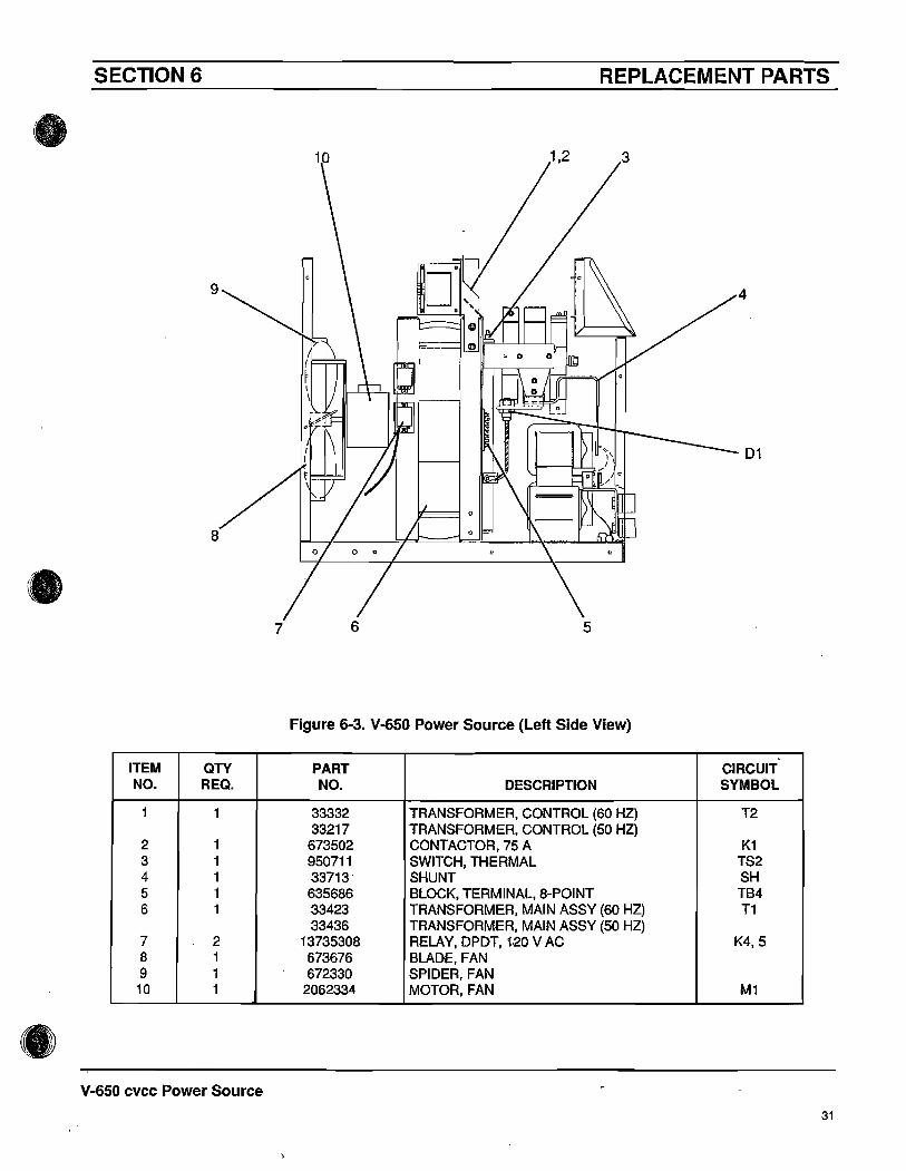
Figure G-3. V-GSO Power Source (Left Side View)
ITEM QTY PART CIRCUITNO. REQ. NO. DESCRIPTION SYMBOL
1 1 33332 TRANSFORMER, CONTROL (60 HZ) T233217 TRANSFORMER, CONTROL (50 HZ)
2 1 673502 CONTACTOR, 75 A K13 1 950711 SWITCH, THERMAL TS24 1 33713· SHUNT SH5 1 635686 BLOCK, TERMINAL, 8-POINT TB46 1 33423 TRANSFORMER, MAIN ASSY (60 HZ) T1
33436 TRANSFORMER, MAIN ASSY (50 HZ)7 2 13735308 RELAY, DPDT, 1·20 V AC K4,58 1 673676 BLADE. FAN9 1 672330 SPIDER. FAN
10 1 2062334 MOTOR, FAN M1
V-G50 cvcc Power Source
31

SECTION 6 REPLACEMENT PARTS
•
5
BRIDGE ASSY (REFERTO FIGURE 6-5)
4 3
2 •Figure 6~4. V-650 Power Source (Right Side View)
ITEM QTY PART CIRCUITNO. REQ. NO. DESCRIPTION SYMBOL
1 1 951541 BLOCK, TERMINAL, 20-POINT TB22 1 833328 BOARD, TERMINAL (60 HZ) T81
833171 BOARD, TERMINAL (50 HZ)3 2 951201 FUSE, 10 A, 600 V F1,24 1 17300020 RESISTOR, 20 OHM, 300 W RS5 1 33575 INDUCTOR ASSEMBLY L1
V·650 cvcc Power Source
32
•

SECTION 6 REPLACEMENT PARTS
5
•
Figure 6-5. Bridge Assembly
2
ITEM QTY PART CIRCUITNO. REQ. NO. DESCRIPTION SYMBOL
1 6 13735018 CORE, TOROID (fOR INDUCTORS l2-7)2 6 950841 THYRISTOR, SCR SCR1-63 1 950768 DIODE, RECTIFIER, 300 A 014 2 950711 SWITCH, THERMAL TS1-25 6 672348 CAPACITOR, .01 uF, 1.0 KV C1-6
V-650 cvcc Power Source
33
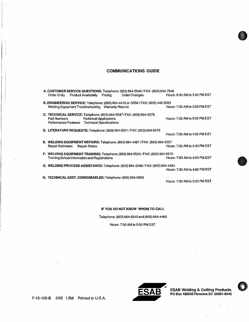
COMMUNICATIONS GUIDE
.A. CUSTOMER SERVICE QUESTIONS: Telephone: (803) 664-"5540 {FAX: (800}'634-7548Order Entry Product Availability Pricing Order Changes Hours: 8:30 AM to 5:00 PM EST
B. ENGINEERING SERVICE: Telephone: (803) 664-4416 or -'5550/ FAX: (800) 446-569~Welding Equipment Troubleshooting Warranty Returns Hours: 7:30 AM to 5:00 PM EST
·C. TECHNICAL SERVICE: Telephone: (803) 664-5547/ FAX: (803)'664-5575Part Numbers Technical ApplicationsPerformance Features Technical Specifications
D. LITERATURE REQUESTS: Telephone: (803) 664-5501 IFAX: (803) 664-5575
Hours: 7:30 AM to 5:00 PM EST
Hours: 7:30 AM to 4:00 PM EST
E. WELDING EQUIPMENT REPAIRS: Telephone: (803) 664-4487/ FAX: (803) 664-5557Repair Estimates Repair Status Hours: 7:30 AM to 3:30 PM EST
F. WELDING EQUIPMENT TRAINING: Telephone: (803) 664-5524/ FAX: (803) 664-5575Training School Information and Registrations Hours: 7:30 AM to 4:00 PM EST
G. WELDING PROCESS ASSISTANCE: Telephone: (803) 664-4248/ FAX: (803) 664-4454Hours: 7:30 AM to 4:00 PM EST
H. TECHNICAL ASST. CONSUMABlES: Telephone: (800) 934-9353Hours: 7:30 AM to 5:00 PM EST
IF YOU DO NOT KNOW WHOM TO CALL
Telephone: (803) 664-5540 and (803) 664-4460
Hours: 7:30 AM to 5:00 PM EST
F-15-100-B 3/95 1.5M Printed in U.S.A.
~
ESAB~
ESAB Welding & Cutting ProductsPO Box 100545 Florence SC 29501-0545