v-71 power unit service manual - meyer...
TRANSCRIPT

FORM NO. 1-1048January 2012
V-71power unit
service manual
© 2012 Printed in the U.S.A.
Meyer Products LLC18513 Euclid Ave. • Cleveland, Ohio 44112-1084
Phone 486-1313 (Area Code 216)www.meyerproducts.com• email [email protected]
FOREWARD
This Service Manual includes complete information for servicing the following Electro Lift® Units:
V-71 Super V Hydraulic Unit
IMPORTANT: Maintenance and repairs must be performed with the moldboard on the
ground.
The information is grouped according to the type of work being performed, such as diagnosis andtesting, disassembly and reassembly. Special tools and specifications are also included in this manual.
All information, illustrations and product descriptions contained in this manual are correct at publicationtime. We do, however, reserve the right to make changes at any time without prior notice.
MEYER PRODUCTS INC.
SECTION INDEX
Section Number Section Title ..................................................... Page
0 GENERAL INFORMATION ANDMAINTENANCE ........................................................ 1
1 GENERAL DESCRIPTION ANDTHEORY OF OPERATION ...................................... 5
2 DIAGNOSIS ............................................................ 183 REPAIR PROCEDURE .............................................. 344 SPECIFICATIONS ..................................................... 55
Meyer Products Inc. reserves the right, under its continuing product improvement program, to change construction ordesign details, specifications and prices without notice or without incurring any obligation.

SECTION 0 - GENERAL INFORMATION AND MAINTENANCE
CONTENTS
GENERAL INFORMATION .................................................. 2
• MODEL IDENTIFICATION .................................................... 2
• MODEL IDENTIFICATION AND
SERIAL NUMBER LOCATION .............................................. 2
MAINTENANCE ................................................................... 2
• GENERAL MAINTENANCE ................................................... 2
• CLEANLINESS ................................................................. 2
• VEHICLE ELECTRICAL SYSTEM........................................... 2
• CHECK REGULARLY ........................................................ 2
POST-SEASON MAINTENANCE ........................................... 2
• MEYER HYDRAULIC FLUID M-1 ......................................... 2
• REPLACEMENT OF HYDRAULIC FLUID .................................. 2
• PROTECTION AGAINST RUST
AND CORROSION ............................................................ 3
-1-

Vehicle Electrical System
Maximum performance and efficiency of the ElectroLift® unit requires that the vehicle’s electrical systembe properly maintained and consist of:
Battery ----------- 70 Amp. Hr. Minimum or550 Cold Cranking Amps.
Alternator ------ 60 Amp. Minimum
Check Regularly
1. Battery Terminals - Must be clean and free ofcorrosion.
2. Electrical Connections - Must be free of corrosionand tight.
3. Battery - Must be in first-class condition.4. Alternator (or Generator) and Regulator - Must be
functioning to specifications.5. Hydraulic Fluid Reservoir Level - A significant drop
in hydraulic fluid level indicates a leak which mustbe located and corrected. Insufficient hydraulic fluidmay result in severe damage.
POST-SEASON MAINTENANCE
Meyer Hydraulic Fluid M-1.
Meyer Hydraulic Fluid M-1 is a specially formulatedmineral oil which maintains an almost constantviscosity from normal to sub-zero temperatures.Because it remains free flowing at extremely lowtemperatures, the performance and efficiency are notaffected.
Meyer Hydraulic Fluid M-1 also contains an additivewhich neutralizes moisture accumulating in the fluiddue to condensation. It is effective for a maximum ofone year’s use.
Meyer Products Inc. will not be liable for damagesresulting from the use of inferior or other fluids oroils.
GENERAL INFORMATION
Model IdentificationThe V-71 unit is an electrically powered hydraulicmechanism specifically designed for use with theMeyer E-Z Mount Plus Super-V Snow Plow system.
Model Identification and Serial Number LocationInclusion of the model number and serial number isextremely important when writing up warranty claimforms and product report forms for proper evaluationand follow up.
The basic model number is located on the nameplate (plastic cover). The serial number is locatedon the name plate decal underneath the plastic cover.
MAINTENANCEThe following maintenance information is intended asa basic guide for providing the V-71 unit with the properservice and care. Sustained heavy duty operation oroperating under adverse conditions may necessitatemore frequent servicing.
General Maintenance
CleanlinessThe greatest enemy to any hydraulic system is dirt orcontamination. Therefore, cleanliness must be stressedat the time of installation, servicing and repairing.
-2-

Replacement of Hydraulic Fluid
After a season’s use, completely drain the hydraulicfluid (including hydraulic fluid in hoses andcylinders). Drain fluid through filler hole shown inFigure 0-1 or drain hole in base by completelyretracting lift rod and unbolting unit to pour fluidout or using a suction pump. Disconnect the fittingsat the Angling cylinders and completely retract thecylinder rods and purge cylinders and hoses of allhydraulic fluid. Flush the complete system includingunit, hoses and angling rams with the M-2 FlushingFluid, or a non wax (Napthenic) cleaner. If kerosene(Parrafinic) is used to flush the system, the systemmust be flushed again to remove any kerosene withM-2 Flushing Fluid, or a (Napthenic) based cleanerthat is wax free .
Refill V-71 unit with M-1 Fluid by fully retracting lift rod(Ram) and filling reservoir to just below the filler neck.Fill and bleed hoses and Power Angling cylinders byloosening hydraulic fittings at cylinders until they leak.Power angle wings repeatedly from one side to theother until fluid flows steadily from the leaking fittingswhile maintaining a constant check on the reservoirfluid level.
Raise and lower the plow several times and with liftrod fully retracted, give a final check to the fluidlevel and replace filler plug. Proper fluid level isachieved when the plow can be fully raised andboth plow wings are extended into the Scoopposition.
Protection Against Rust and Corrosion
When the V-71 unit is not used for extended periods,protect the chromed lift rod (Ram) by fully extendingit and coating it with chassis lubricant. Full extensionof the lift rod (Ram) fills the cylinder with hydraulicfluid. Also put the plow wings in the retractedposition so the Angle cylinders do not expose thechrome rod.
-3-
Drain Plug
Filler Cap
FIGURE 0-1 V-70
M-2 Flush Fluid
M-1 Hydraulic Fluid
SECTION 1 - GENERAL DESCRIPTION AND THEORY OF OPERATION
CONTENTS
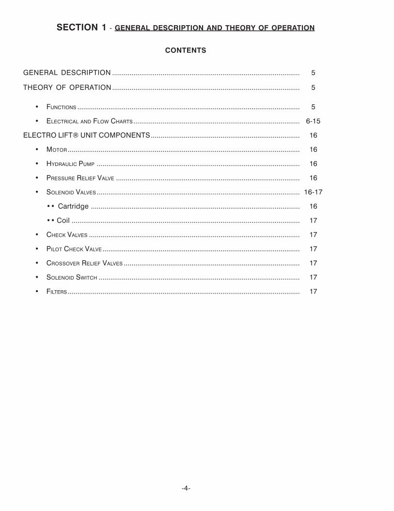
GENERAL DESCRIPTION ................................................................................................. 5
THEORY OF OPERATION................................................................................................. 5
• FUNCTIONS ................................................................................................................... 5
• ELECTRICAL AND FLOW CHARTS ...................................................................................... 6-15
ELECTRO LIFT® UNIT COMPONENTS............................................................................. 16
• MOTOR........................................................................................................................ 16
• HYDRAULIC PUMP ......................................................................................................... 16
• PRESSURE RELIEF VALVE ............................................................................................... 16
• SOLENOID VALVES ......................................................................................................... 16-17
•• Cartridge ............................................................................................................ 16
•• Coil ...................................................................................................................... 17
• CHECK VALVES ............................................................................................................. 17
• PILOT CHECK VALVE ...................................................................................................... 17
• CROSSOVER RELIEF VALVES ........................................................................................... 17
• SOLENOID SWITCH ........................................................................................................ 17
• FILTERS ........................................................................................................................ 17
-4-
GENERAL DESCRIPTION
V-71 unit is an electrically powered and electricallycontrolled hydraulic mechanism specificallydesigned for use with Meyer Super-V Snow Plows.The V-71 raises and lowers the plow with an integral 8"stroke hydraulic cylinder.
In addition to raising and lowering the plowhydraulically, the V-71 angles the plow wingshydraulically, left and right, via remote double actinghydraulic cylinders.
The Electro Lift® unit consists of a specially designedhigh torque 12-volt DC motor which is directly coupledto a gear-type hydraulic pump. The pump obtains itssupply of hydraulic fluid from an integral reservoir whichtotally surrounds the integral hydraulic cylinder whichraises and lowers the plow.
The V-70 includes an integral valve body which containssix electrically controlled solenoid valve cartridges.Solenoid valve cartridge “S1”, “S2”, “S3”, “S4”, “S5”,“S6”, “S7” and “S8”.
Additional components which control and supplyelectrical current to the V-71 unit is an operatorcontrolled Pistol Grip Controller, a solenoid switch tosupply high amperage current to the unit’s motor(motor solenoid)
THEORY OF OPERATION
FUNCTIONS
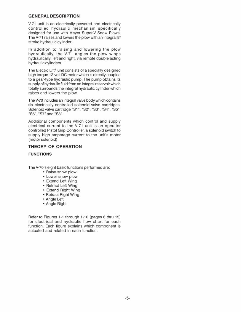
The V-70’s eight basic functions performed are:• Raise snow plow• Lower snow plow• Extend Left Wing• Retract Left Wing• Extend Right Wing• Retract Right Wing• Angle Left• Angle Right
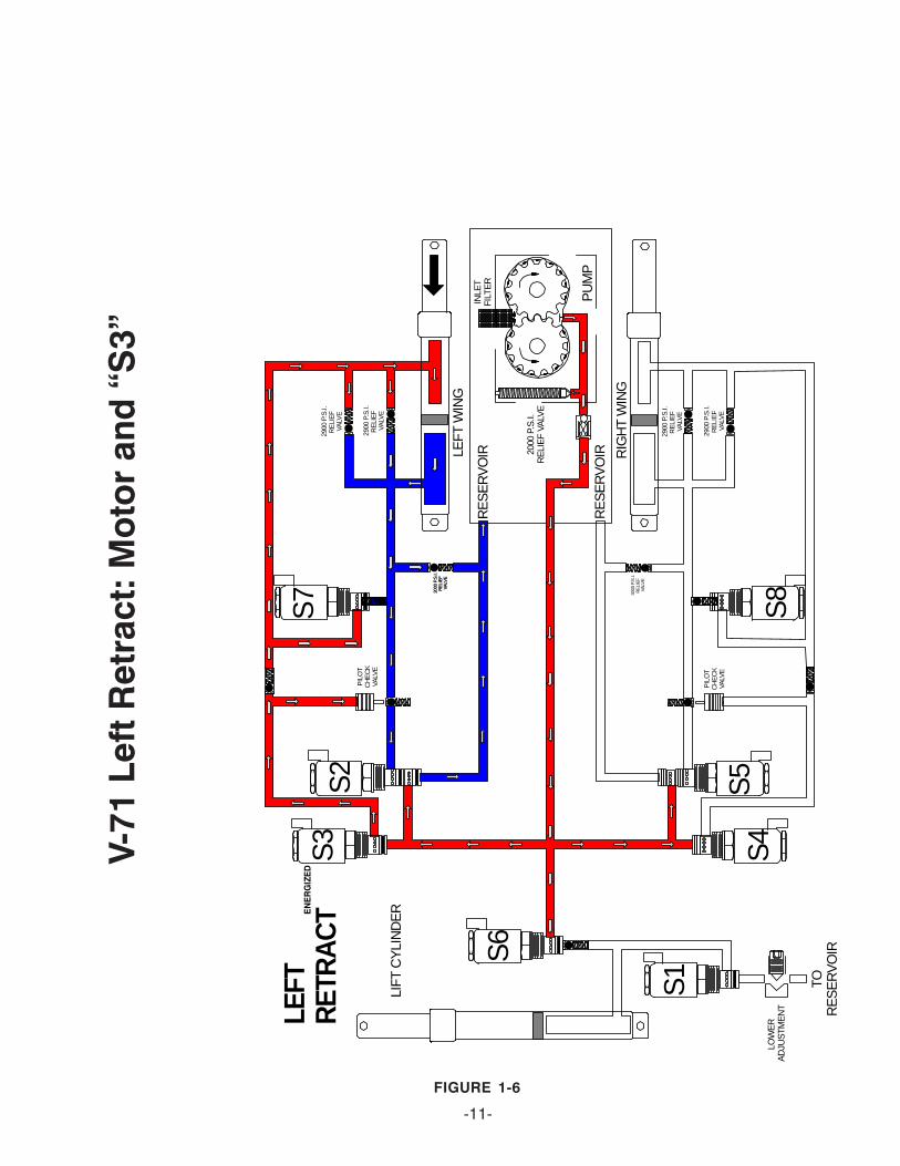
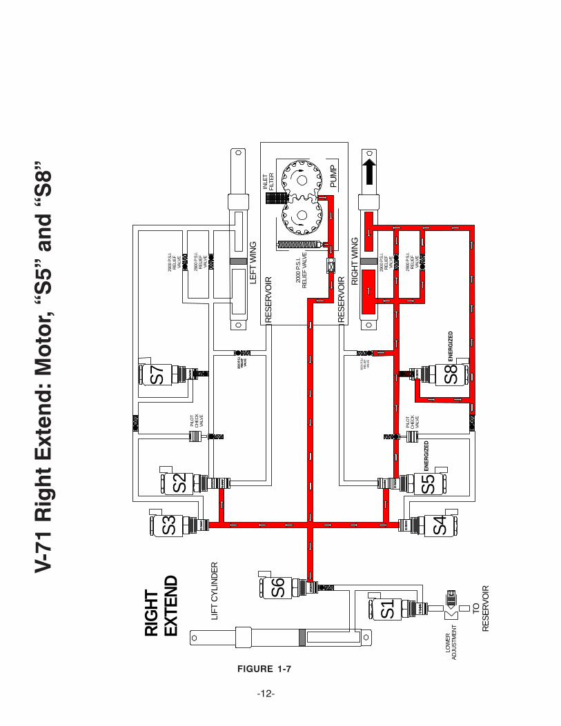
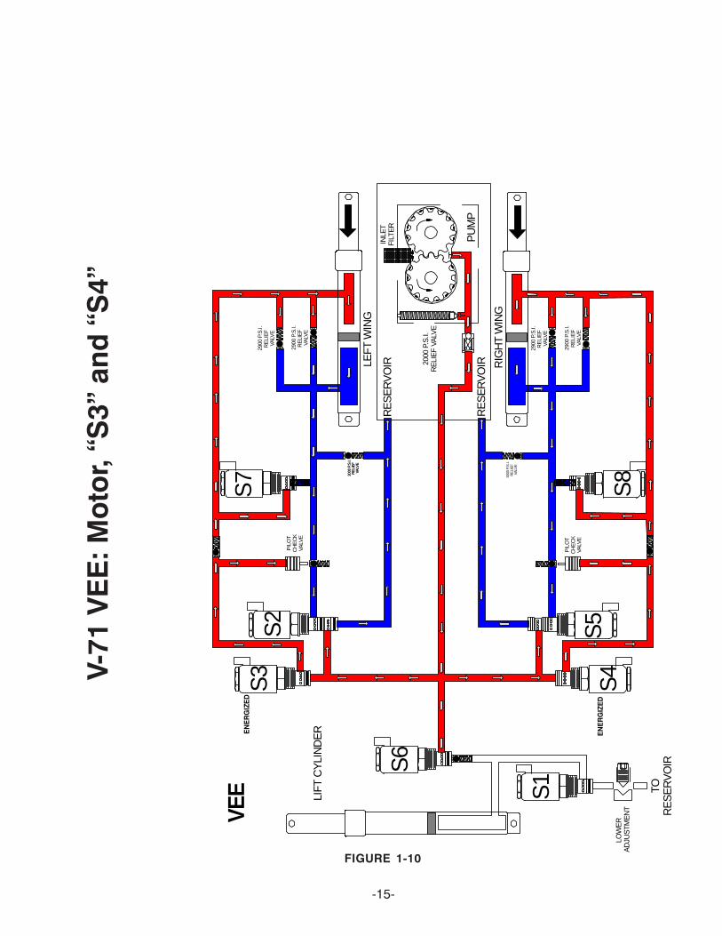
Refer to Figures 1-1 through 1-10 (pages 6 thru 15)for electrical and hydraulic flow chart for eachfunction. Each figure explains which component isactuated and related in each function.
-5-

V-71
Rai
se: M
oto
r an
d “
S6”
-6-FIGURE 1-1
PU
MP
RA
ISE S
6
S3
S7
S2
RE
SE
RV
OIRLE
FT
WIN
G
LIFT
CY
LIN
DE
R
LOW
ER
A
DJU
STM
EN
T
INLE
TF
ILT
ER
2000
P.S
.I.R
ELI
EF
VA
LVE
PIL
OT
CH
EC
KVA
LVE
2900
P.S
.I.R
ELI
EF
VA
LVE
2000
P.S
.I.R
ELI
EF
VA
LVE
3000
P.S
.I.R
ELI
EF
VA
LVE
2900
P.S
.I.R
ELI
EF
VALV
E
S1
RE
SE
RV
OIR
S8
S5
S4
RIG
HT
WIN
G
TOR
ES
ER
VO
IR
2900
P.S
.I.R
ELI
EF
VA
LVE
2900
P.S
.I.R
ELI
EF
VA
LVE
PIL
OT
CH
EC
KVA
LVE
3000
P.S
.I.R
ELI
EF
VA
LVE
EN
ER
GIZ
ED
-7-FIGURE 1-2
V-71
Lo
wer
: “S
1” O
nly
PU
MP
LOW
ER S6
S3
S7
S2
RE
SE
RV
OIRLE
FT
WIN
G
LIFT
CY
LIN
DE
R
LOW
ER
A
DJU
STM
EN
T
INLE
TF
ILT
ER
2000
P.S
.I.R
ELI
EF
VA
LVE
PIL
OT
CH
EC
KVA
LVE
2900
P.S
.I.R
ELI
EF
VA
LVE
2000
P.S
.I.R
ELI
EF
VA
LVE
3000
P.S
.I.R
ELI
EF
VA
LVE
2900
P.S
.I.R
ELI
EF
VALV
E
S1
RE
SE
RV
OIR
S8
S5
S4
RIG
HT
WIN
G
TOR
ES
ER
VO
IR
2900
P.S
.I.R
ELI
EF
VA
LVE
2900
P.S
.I.R
ELI
EF
VA
LVE
PIL
OT
CH
EC
KVA
LVE
3000
P.S
.I.R
ELI
EF
VA
LVE
EN
ER
GIZ
ED

-8-
FIGURE 1-3
V-71
Ang
le L
eft:
Mo
tor,
“S3”
, “S
5” a
nd “
S8”
PU
MP
AN
GLE
LEFT
S6
S3
S7
S2
RE
SE
RV
OIRLE
FT W
ING
LIF
T C
YLI
ND
ER
LOW
ER
A
DJU
STM
EN
T
INLE
TF
ILT
ER
2000
P.S
.I.R
ELI
EF
VA
LVE
PIL
OT
CH
EC
KVA
LVE
2900
P.S
.I.R
ELI
EF
VA
LVE
2000
P.S
.I.R
ELI
EF
VA
LVE
3000
P.S
.I.R
ELI
EF
VA
LVE
2900
P.S
.I.R
ELI
EF
VALV
E
S1
RE
SE
RV
OIR
EN
ER
GIZ
ED
S8
S5
S4
RIG
HT
WIN
G
TOR
ES
ER
VO
IR
2900
P.S
.I.R
ELI
EF
VALV
E
2900
P.S
.I.R
ELI
EF
VALV
E
PIL
OT
CH
EC
KVA
LVE
3000
P.S
.I.R
ELI
EF
VA
LVE
EN
ER
GIZ
ED
EN
ER
GIZ
ED

-9-
FIGURE 1-4
V-71
Ang
le R
igh
t: M
oto
r “S
2”, “
S4”
and
“S
7”
PU
MP
AN
GLE
RIG
HT S
6
S3
S7
S2
RE
SE
RV
OIRLE
FT W
ING
LIF
T C
YLI
ND
ER
LOW
ER
A
DJU
STM
EN
T
INLE
TF
ILT
ER
2000
P.S
.I.R
ELI
EF
VA
LVE
PIL
OT
CH
EC
KVA
LVE
2900
P.S
.I.R
ELI
EF
VA
LVE
2000
P.S
.I.R
ELI
EF
VA
LVE
3000
P.S
.I.R
ELI
EF
VA
LVE
2900
P.S
.I.R
ELI
EF
VALV
E
S1
RE
SE
RV
OIR
EN
ER
GIZ
ED
S8
S5
S4
RIG
HT
WIN
G
TOR
ES
ER
VO
IR
2900
P.S
.I.R
ELI
EF
VALV
E
2900
P.S
.I.R
ELI
EF
VALV
E
PIL
OT
CH
EC
KVA
LVE
3000
P.S
.I.R
ELI
EF
VA
LVE
EN
ER
GIZ
ED
EN
ER
GIZ
ED

-10-
FIGURE 1-5
V-71
Lef
t Ext
end
: Mo
tor,
“S2”
and
“S
7” PU
MP
LEFT
EX
TEN
D
S6
S3
S7
S2
RE
SE
RV
OIRLE
FT W
ING
LIF
T C
YLI
ND
ER
LOW
ER
A
DJU
STM
EN
T
INLE
TFI
LTE
R
2000
P.S
.I.R
ELI
EF
VALV
E
PIL
OT
CH
EC
KVA
LVE
2900
P.S
.I.R
ELI
EF
VA
LVE
2000
P.S
.I.R
ELI
EF
VALV
E
3000
P.S
.I.R
ELI
EF
VALV
E
2900
P.S
.I.R
ELI
EF
VA
LVE
S1
RE
SE
RV
OIR
EN
ER
GIZ
ED
S8
S5
S4
RIG
HT
WIN
G
TOR
ES
ER
VO
IR
2900
P.S
.I.R
ELI
EF
VA
LVE
2900
P.S
.I.R
ELI
EF
VA
LVE
PIL
OT
CH
EC
KVA
LVE
3000
P.S
.I.R
ELI
EF
VA
LVEE
NE
RG
IZE
D
-11-
FIGURE 1-6
V-71
Lef
t Ret
ract
: Mo
tor
and
“S
3”
PU
MP
LEFT
RE
TRA
CT
S6
S3
S7
S2
RE
SE
RV
OIRLE
FT W
ING
LIF
T C
YLI
ND
ER
LOW
ER
A
DJU
STM
EN
T
INLE
TFI
LTE
R
2000
P.S
.I.R
ELI
EF
VALV
E
PIL
OT
CH
EC
KVA
LVE
2900
P.S
.I.R
ELI
EF
VA
LVE
2000
P.S
.I.R
ELI
EF
VALV
E
3000
P.S
.I.R
ELI
EF
VALV
E
2900
P.S
.I.R
ELI
EF
VA
LVE
S1
RE
SE
RV
OIR
EN
ER
GIZ
ED
S8
S5
S4
RIG
HT
WIN
G
TOR
ES
ER
VO
IR
2900
P.S
.I.R
ELI
EF
VA
LVE
2900
P.S
.I.R
ELI
EF
VA
LVE
PIL
OT
CH
EC
KVA
LVE
3000
P.S
.I.R
ELI
EF
VA
LVE
-12-
FIGURE 1-7
V-71
Rig
ht E
xten
d: M
oto
r, “S
5” a
nd “
S8”
PU
MP
RIG
HT
EX
TEN
D
S6
S3
S7
S2
RE
SE
RV
OIRLE
FT W
ING
LIF
T C
YLI
ND
ER
LOW
ER
A
DJU
STM
EN
T
INLE
TF
ILT
ER
2000
P.S
.I.R
ELI
EF
VA
LVE
PIL
OT
CH
EC
KVA
LVE
2900
P.S
.I.R
ELI
EF
VA
LVE
2000
P.S
.I.R
ELI
EF
VA
LVE
3000
P.S
.I.R
ELI
EF
VA
LVE
2900
P.S
.I.R
ELI
EF
VALV
E
S1
RE
SE
RV
OIR
S8
S5
S4
RIG
HT
WIN
G
TOR
ES
ER
VO
IR
2900
P.S
.I.R
ELI
EF
VALV
E
2900
P.S
.I.R
ELI
EF
VALV
E
PIL
OT
CH
EC
KVA
LVE
3000
P.S
.I.R
ELI
EF
VA
LVE
EN
ER
GIZ
ED
EN
ER
GIZ
ED

-13-
FIGURE 1-8
V-71
Rig
ht R
etra
ct: M
oto
r an
d “
S4”
PU
MP
RIG
HT
RE
TRA
CT
S6
S3
S7
S2
RE
SE
RV
OIRLE
FT W
ING
LIF
T C
YLI
ND
ER
LOW
ER
A
DJU
STM
EN
T
INLE
TF
ILT
ER
2000
P.S
.I.R
ELI
EF
VA
LVE
PIL
OT
CH
EC
KVA
LVE
2900
P.S
.I.R
ELI
EF
VA
LVE
2000
P.S
.I.R
ELI
EF
VA
LVE
3000
P.S
.I.R
ELI
EF
VA
LVE
2900
P.S
.I.R
ELI
EF
VALV
E
S1
RE
SE
RV
OIR
S8
S5
S4
RIG
HT
WIN
G
TOR
ES
ER
VO
IR
2900
P.S
.I.R
ELI
EF
VALV
E
2900
P.S
.I.R
ELI
EF
VALV
E
PIL
OT
CH
EC
KVA
LVE
3000
P.S
.I.R
ELI
EF
VA
LVE
EN
ER
GIZ
ED

-14-
FIGURE 1-9
V-71
Sco
op
: Mo
tor,
“S2”
, “S
5”, “
S7”
and
“S
8”
PU
MP
SC
OO
P S6
S3
S7
S2
RE
SE
RV
OIRLE
FT W
ING
LIF
T C
YLI
ND
ER
LOW
ER
A
DJU
STM
EN
T
INLE
TFI
LTE
R
2000
P.S
.I.R
ELI
EF
VALV
E
PIL
OT
CH
EC
KVA
LVE
2900
P.S
.I.R
ELI
EF
VA
LVE
2000
P.S
.I.R
ELI
EF
VALV
E
3000
P.S
.I.R
ELI
EF
VALV
E
2900
P.S
.I.R
ELI
EF
VA
LVE
S1
RE
SE
RV
OIR
S8
S5
S4
RIG
HT
WIN
G
TOR
ES
ER
VO
IR
2900
P.S
.I.R
ELI
EF
VA
LVE
2900
P.S
.I.R
ELI
EF
VA
LVE
PIL
OT
CH
EC
KVA
LVE
3000
P.S
.I.R
ELI
EF
VA
LVE
EN
ER
GIZ
ED
EN
ER
GIZ
ED
EN
ER
GIZ
ED
EN
ER
GIZ
ED
-15-
FIGURE 1-10
V-71
VE
E: M
oto
r, “S
3” a
nd “
S4”
PU
MP
VE
E
S6
S3
S7
S2
RE
SE
RV
OIRLE
FT W
ING
LIF
T C
YLI
ND
ER
LOW
ER
A
DJU
STM
EN
T
INLE
TFI
LTE
R
2000
P.S
.I.R
ELI
EF
VALV
E
PIL
OT
CH
EC
KVA
LVE
2900
P.S
.I.R
ELI
EF
VA
LVE
2000
P.S
.I.R
ELI
EF
VALV
E
3000
P.S
.I.R
ELI
EF
VALV
E
2900
P.S
.I.R
ELI
EF
VA
LVE
S1
RE
SE
RV
OIR
EN
ER
GIZ
ED
S8
S5
S4
RIG
HT
WIN
G
TOR
ES
ER
VO
IR
2900
P.S
.I.R
ELI
EF
VA
LVE
2900
P.S
.I.R
ELI
EF
VA
LVE
PIL
OT
CH
EC
KVA
LVE
3000
P.S
.I.R
ELI
EF
VA
LVE
EN
ER
GIZ
ED

Under a condition, such as when a hydrauliccylinder is extended to the end of its stroke,eliminating additional space for the pressurizedhydraulic oil to be pumped into, the alternateopening and closing of the poppet valve controlsthe pump’s pressure output and provides an escapefor the pressurized hydraulic fluid.
The pressure relief valve used in the V-71 pump, whilemore sophisticated than the one described, functionsin the same manner. The pump pressure relief valvemay be pre-set and adjustable to the specified pressureof 2000 P.S.I.
SOLENOID VALVES
Hydraulic valves are simple in concept and all havethe same basic function: Control the direction of oilflow.
Each Solenoid Valve consists of two components:the Cartridge and the Coil.
Cartridge
The Cartridge consists of the hydraulic valvemechanism and an armature which enables thevalve mechanism to be operated and controlledelectrically. The Cartridge is designed to screw inand out of the V-71 unit much like the typical “sparkplug”.
FIGURE 1-13
COIL
VALVE SPOOL
WINDING
ARMATURE
FIGURE 1-11
ELECTRO LIFT® UNIT COMPONENTS
RESERVOIR
ELECTRICMOTOR
FLOW
OUTLET LINE
INTAKE LINE
PUMP CHAMBER
PUMP HOUSING
DRIVE GEARDRIVEN GEAR
FLOW
OUTLET PORT
POPPET VALVE
VALVE SPRING
PUMP HOUSING
INLET PORT
FIGURE 1-12
-16-
PRESSURE RELIEF VALVE
A basic pressure relief valve is shown inFigure 1-12. It consists of a poppet valve and avalve spring. Both are located in a passagewhich connects the inlet passage to the outletpassage. The poppet valve is normally held closedby the valve spring, sealing the connecting passagefrom the pressurized outlet passage. The poppetvalve, being a piston, is exposed to the pressurizedhydraulic fluid in the outlet passage. Whenever thehydraulic pressure against the poppet valvebecomes greater than the pressure being exerted
on the poppet valve from the opposite direction bythe valve spring, the poppet valve will open. Thisallows some of the pressurized hydraulic fluid toflow through the connecting passage to the nonpressurized inlet passage. The effect is to lower thepressure in the outlet passage which will allow thevalve spring to close the poppet valve again.
V-71 UNIT COMPONENTS
MOTOR (4-1/2”)
Two terminal
The motor is a four pole, electromagnet motor whichconsists primarily of a 4-1/2" diameter solid steel frame,armature, brushes, field coils and pole pieces. Thismotor can be used on vehicles with either the commonnegative ground electrical system or the positiveground electrical system.
HYDRAULIC PUMP
The pump in a hydraulic system employs an externalsource of power to apply a force to a liquid. A pumpdevelops no power of its own. It simply transferspower from an external source (the electric motoron the V-71 unit) to the liquid in the hydraulic system.
The basic operating principles of the hydraulic pumpused in the V-71 unit is quite simple. Figure 1-11illustrates the basic components of a positivedisplacement gear type pump and their functions. Thepumping action takes place within the pump chamberwhich is connected to the reservoir by the intake line.The pump chamber has an outlet line in which the liquidunder motion and pressure leaves the pump to performwork.

designed to open at a specific pressure.In this instance, the pressure is not produced bythe pump but rather by the damaging force. As anexample, assume that the right corner of the plowruns into the end of a curb. The impact will attemptto collapse the right power angling cylinder. As aresult, very high hydraulic pressure is producedwithin the cylinder. When the produced pressure ishigh enough, it opens the crossover relief valve,allowing the highly pressurized hydraulic fluid toflow directly to the left power angling cylinder.
When the crossover relief valve functions in this manner,the excessive pressure is released, the excessive energyproduced by the impact is absorbed, and the result isonly a change in angled position of the plow.
The crossover relief valve is factory set to the specifiedpressure of 2900 & 3000 P.S.I. this setting is adjustable.
-17-
ELECTRO LIFT® UNIT COMPONENTS CONT.
Coil
The Coil is the electrical component which operatesthe Cartridge’s valve mechanism by producingmagnetism which pulls the Cartridge’s armaturetoward it. Since the armature is connected to thevalve mechanism’s only moving part, it is pulledby the armature.
Figure 1-13 illustrates the typical Coil. Wheneverelectrical current flows to the Coil, it flowsthrough the winding, which consists ofnumerous turns of copper wire. The flow ofcurrent through the winding produces amagnetic field which pulls the soft iron armaturefurther into the Coil.
The armature pulls the valve spool or poppetvalve into its alternate (energized) position. Notillustrated is an integral coil spring, which iscompressed when the armature is pulled by themagnetism.
When the current flow ceases, the magnetic fielddisappears and the compressed coil springpushes the armature back to its original(de-energized) position.
CHECK VALVES
Check valves are very simple devices that have twobasic functions: They prevent fluid from passingthrough them in one direction, but they allow fluidto pass through them in the opposite direction.
In the V-71 a pump check valve is used to preventhydraulic fluid from leaking back through the pumpto the reservoir.
DOUBLE ACTING PILOT CHECK VALVE
The pilot check valve is more sophisticated in thatit incorporates a piston in addition to the ball, seatand spring. The pilot check valve opens a passageway using hydraulic pressure which applies forceto a piston which then pushes a ball of of its seat toallow fluid to pass thru.
CROSSOVER RELIEF VALVE
When plowing snow, a snow plow can be exposedto damaging forces caused by impact with hiddenobstructions, ends of curbs, etc. With power angling,these damaging forces can damage not only thesnow plow but also the vehicle. The crossover reliefvalve has the function of protecting the snow plowsystem against these damaging forces under normalsnow plowing conditions. The crossover relief valve,cannot protect the system from damaging forcesthat are too great due to abusive snow plowingconditions.
Basically, the crossover relief valve functions exactlylike the previously described pump relief valve. It’s
SOLENOID SWITCH
The V-71 motor requires more current or amperage tooperate than the vehicle wiring, vehicle ignition switchor toggle switches have the capacity to handle. Thesolenoid switch is essentially a heavy duty switch withthe capacity to handle the heavy current required bythe motor. It is closed electrically by the solenoid toconvey the heavy current directly from the vehiclebattery via heavy gauge electrical cable. The solenoid,which functions essentially the same as the previouslydescribed solenoid valves, receives its low amperagecurrent at the proper times via the wiring harness. Thissolenoid must be grounded to operate properly.
FILTERS
Cleanliness is perhaps the single most importantingredient in assuring a hydraulic system’s reliability.Should the hydraulic fluid become contaminated,malfunction and permanent damage to thehydraulic system may occur. For this reason, the V-71unit is equipped with a filter system consisting of:
• A fine screen strainer on the reservoir pump inlet.
With this system, the hydraulic fluid is filtered as itleaves the reservoir on its way to the pump. Periodiccleaning of the filter screen is achieved be removingthe reservoir tank shown in the dis-assembly section.
IMPORTANT:
Should the hydraulic fluid become contaminated,it will be necessary to replace all the hydraulic oil inthe system. The complete system (hydraulic unit,power angling cylinders and hoses) should beflushed. Flush the system with Meyer Hydra-Flush™Fluid M-2.

-18-
SECTION 2 - DIAGNOSIS
CONTENTS
GENERAL INFORMATION 19
TESTING TIPS 19
TROUBLE SHOOTING 20-33

DIAGNOSTIC FLOW CHART FORV-71 Unit
These charts are intended to be used as an aid in diagnosing problems on the V-68 unit. They are not a substitute for factory trainingand experience. Be certain to read the General Information and Testing Tips sections before attempting any troubleshooting.
IMPORTANT: Maintenance and repairs must be performed with the moldboard on the ground.
General InformationBefore any troubleshooting is started, make certain the following conditions are met.
1. The power angling cylinders must be installed correctly on to the plow assembly. The left cylinder (Driver’s side) has twohoses. Attach the left wing 1/4" hose to the rod or live end of left ram. Attach the left wing 3/8" hose to the fixed endof left ram. Attach the right wing 1/4" hoseto the rod or live end of right ram. Attach the right wing 3/8" hose to thefixed end of right ram. See Figure 1
2. The solenoid wires must be on their proper coil. See Figure 1
TESTING TIPS
-19-
Many tests do not require removing the Electro Lift® unit from the vehicle. However, more thorough testing can beperformed using the Meyer Test Stand which allows direct pressure and amperage readings.
1. Using a screwdriver or other small tool to check for magnetism of the solenoid coils “S1”, “S2”, “S3”, “S4”, “S5”, “S6”, “S7” and“S8”. Place the tool on the nut securing the coil and have an assistant operate the switch. You should feel strong magneticattraction.
2. Use a test light or volt meter to determine whether there is power at the harness.3. When determining AMP draw of the motor, always obtain the highest value possible, i.e, at maximum raise or maximum
angle with motor running.4. The pump shaft of a good pump can be turned smoothly using two fingers. If it can’t be turn easily, the pump is too tight and
must be replaced.5. Pump pressure can be measured at an angle hose (note pressure at full angle) Note: The V-71 Unit has a adjustable pressure relief
valve.6. Flush the complete system including unit, hoses and power angling rams with Meyer Hydra-Flush™ Fluid M-2.
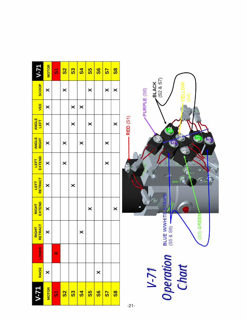
V-71 CONTROLLER OPERATION
• The snow plow should only be in operation when the vehicle ignition switch and the control switch are in the “ON” position.Care should be taken to insure that the control switch is kept dry and free from moisture during normal operation.
• When the control switch is turned “On,” lights illuminate the location of the individual touch pads for the functions of thesnow plow: (Up), (Angle Left),(Left Extend), (Left Retract), (Angle Right), (Right Extend), (Right Retract), (Scoop), (Vee) and(Down).
• Lowering of the snow plow an inch at a time is possible by tapping the down arrow in short intervals. Holding down thedown arrow will activate a float light located in the upper right corner of the control switch. This light indicates the snow plowis now in the Lower/Float position. In this position the snow plow will be able to follow the contour of the road and the snowplow can also be angled to the left or right. Touching the up arrow automatically cancels the Lower/Float position.
• While angling left or right or raising the snow plow if the button is pressed for more than six seconds the operation will becancelled. This feature eliminates unnecessary amp draw from the vehicle charging system.
• This switch is self diagnosing. The monitor light is located in the upper left corner next to the float light of the control switch.When the monitor light turns on and begins to flash the control switch is sensing a problem with a specific coil/connectionon the hydraulic unit. The label below is on the back side of your control switch.
• Reset is accomplished by turning off the ignition switch or by turning the power switch off momentarily and then back on.If the monitor light is still illuminated after attempts to reset the switch have failed, contact your nearest authorized MeyerDistributor for repairs.
Hydraulic Solenoid Color Code:S1 (Red and Black w/white stripe)S2 & S7 (Black and Black w/white stripe)S3 (Green and Black w/white stripe)S4 (Yellow and Black w/white stripe)S5 & S8 (Blue w/white stripe and Black w/white stripe)S6 (Purple and Black w/white stripe)
Figure 1
Drain
Fill
S1
S2
S3
S4
S5S6
S7
S8
LiftCylinderHosePort
Pass Side Live End(1/4 Hose)
Driver Side Live End(1/4 Hose)
Pass Side Fixed End(3/8 Hose)
Driver Side Fixed End(3/8 Hose)

-20-
S1
S2
S3
S5
S6
S7
V-71
O
pera
tion
Cha
rt
V-7
1R
AIS
EL
OW
ER
R
IGH
T
RE
TR
AC
TR
IGH
T
EX
TE
ND
LE
FT
R
ET
RA
CT
LE
FT
E
XT
EN
DA
NG
LE
R
IGH
TA
NG
LE
L
EF
TV
EE
SC
OO
PV
-71
MO
TO
RX
XX
XX
XX
XX
MO
TO
R
S1
XS
1
S2
XX
XS
2
S3
XX
XS
3
S4
XX
XS
4
S5
XX
XS
5
S6
XS
6
S7
XX
XS
7
S8
XX
XS
8
-21-
S1
S2
S3
S5
S6
S7
V-71
O
pera
tion
Cha
rt
V-7
1R
AIS
EL
OW
ER
R
IGH
T
RE
TR
AC
TR
IGH
T
EX
TE
ND
LE
FT
R
ET
RA
CT
LE
FT
E
XT
EN
DA
NG
LE
R
IGH
TA
NG
LE
L
EF
TV
EE
SC
OO
PV
-71
MO
TO
RX
XX
XX
XX
XX
MO
TO
R
S1
XS
1
S2
XX
XS
2
S3
XX
XS
3
S4
XX
XS
4
S5
XX
XS
5
S6
XS
6
S7
XX
XS
7
S8
XX
XS
8

-22-
S1
S2
S3
S5
S6
S7
V-71
O
pera
tion
Cha
rt
V-7
1R
AIS
EL
OW
ER
R
IGH
T
RE
TR
AC
TR
IGH
T
EX
TE
ND
LE
FT
R
ET
RA
CT
LE
FT
E
XT
EN
DA
NG
LE
R
IGH
TA
NG
LE
L
EF
TV
EE
SC
OO
PV
-71
MO
TO
RX
XX
XX
XX
XX
MO
TO
R
S1
XS
1
S2
XX
XS
2
S3
XX
XS
3
S4
XX
XS
4
S5
XX
XS
5
S6
XS
6
S7
XX
XS
7
S8
XX
XS
8
Pres
s A
ngle
righ
t and
the
righ
t win
g re
trac
ts
Pres
s sc
oop
and
the
right
win
g ex
tend
s

-23-
S1
S2
S3
S5
S6
S7
V-71
O
pera
tion
Cha
rt
V-7
1R
AIS
EL
OW
ER
R
IGH
T
RE
TR
AC
TR
IGH
T
EX
TE
ND
LE
FT
R
ET
RA
CT
LE
FT
E
XT
EN
DA
NG
LE
R
IGH
TA
NG
LE
L
EF
TV
EE
SC
OO
PV
-71
MO
TO
RX
XX
XX
XX
XX
MO
TO
R
S1
XS
1
S2
XX
XS
2
S3
XX
XS
3
S4
XX
XS
4
S5
XX
XS
5
S6
XS
6
S7
XX
XS
7
S8
XX
XS
8
Pres
s A
ngle
left
and
the
righ
t win
g ex
tend
s
Pres
s Ve
ean
d th
e rig
ht w
ing
retr
acts

-24-
S1
S2
S3
S5
S6
S7
V-71
O
pera
tion
Cha
rt
V-7
1R
AIS
EL
OW
ER
R
IGH
T
RE
TR
AC
TR
IGH
T
EX
TE
ND
LE
FT
R
ET
RA
CT
LE
FT
E
XT
EN
DA
NG
LE
R
IGH
TA
NG
LE
L
EF
TV
EE
SC
OO
PV
-71
MO
TO
RX
XX
XX
XX
XX
MO
TO
R
S1
XS
1
S2
XX
XS
2
S3
XX
XS
3
S4
XX
XS
4
S5
XX
XS
5
S6
XS
6
S7
XX
XS
7
S8
XX
XS
8
Pres
s A
ngle
righ
t and
the
left
win
g ex
tend
s
Pres
s Ve
ean
d th
e le
ft w
ing
retr
acts

-25-
S1
S2
S3
S5
S6
S7
V-71
O
pera
tion
Cha
rt
V-7
1R
AIS
EL
OW
ER
R
IGH
T
RE
TR
AC
TR
IGH
T
EX
TE
ND
LE
FT
R
ET
RA
CT
LE
FT
E
XT
EN
DA
NG
LE
R
IGH
TA
NG
LE
L
EF
TV
EE
SC
OO
PV
-71
MO
TO
RX
XX
XX
XX
XX
MO
TO
R
S1
XS
1
S2
XX
XS
2
S3
XX
XS
3
S4
XX
XS
4
S5
XX
XS
5
S6
XS
6
S7
XX
XS
7
S8
XX
XS
8
Pres
s A
ngle
left
and
the
left
win
g re
trac
ts

-26-
S1
S2
S3
S5
S6
S7
V-71
O
pera
tion
Cha
rt
V-7
1R
AIS
EL
OW
ER
R
IGH
T
RE
TR
AC
TR
IGH
T
EX
TE
ND
LE
FT
R
ET
RA
CT
LE
FT
E
XT
EN
DA
NG
LE
R
IGH
TA
NG
LE
L
EF
TV
EE
SC
OO
PV
-71
MO
TO
RX
XX
XX
XX
XX
MO
TO
R
S1
XS
1
S2
XX
XS
2
S3
XX
XS
3
S4
XX
XS
4
S5
XX
XS
5
S6
XS
6
S7
XX
XS
7
S8
XX
XS
8

-27-
Snow Plow will not Raise
Does the Snowplow Vee or Scoop?
Yes
No
Does the MotorTurn On?
No
Does the Motor have 12 volts to the red wire when the Raise Switch
is pressed?
No
YesCheck Black ground wire
or replace Motor.
Check Motor Solenoid for ground and 12 volts on both large terminals and small terminal with
White wire.
Does the S6 Solenoid magnetize
when the raise switch is pressed?
Yes Replace the S6Solenoid Cartridge
No
Does the the coil plug Purple and Black w/White stripe
have 12 volts when the raise switch is pressed?
Yes Replace the S6Solenoid Coil
No
Check Harnessand Switch
Yes Pump Pressure2000 P.S.I.
No
Replace Pump Relief Valve
and/or Pump
-28-
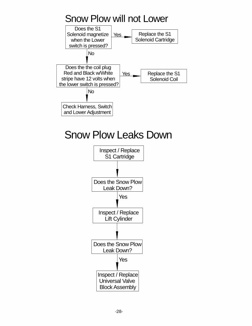
Snow Plow will not LowerDoes the S1
Solenoid magnetize when the Lower
switch is pressed?
Yes Replace the S1Solenoid Cartridge
No
Does the the coil plug Red and Black w/White
stripe have 12 volts when the lower switch is pressed?
Yes Replace the S1Solenoid Coil
No
Check Harness, Switchand Lower Adjustment
Snow Plow Leaks DownInspect / Replace
S1 Cartridge
Does the Snow PlowLeak Down?
Yes
Inspect / ReplaceLift Cylinder
Yes
Inspect / ReplaceUniversal Valve Block Assembly
Does the Snow PlowLeak Down?

-29-
Snow Plow will not Angle Left
Check Harnessand Switch
Does the Snow Plow Extend the Left Wing
No
Yes
Does the Snow plow Retract the Left Wing?
Yes
No See Snow Plow Does Not Retract
Left Wing
See Snow Plow Does Not Extend
Left Wing
Snow Plow will not Extend the Left Wing
Does the the coil plug Black and
Black w/White stripe have 12 volts when the left extend switch is pressed?
Yes Replace the S2 & S7Solenoid Coil
No
Check Harnessand Switch
Does the S2 & S7 Solenoid magnetize
when the Left Extend switch is pressed?
No
Replace the S2 & S7Solenoid Cartridge
Yes
Snow Plow will not Retract the Left Wing
Does the the coil plug Green and Black w/White stripe have 12 volts when
the left retract switch is pressed?
Yes Replace the S3Solenoid Coil
No
Check Harnessand Switch
Does the S3 Solenoid magnetize
when the Left Retract switch is pressed?
No
Replace the S3Solenoid Cartridge
Yes

-30-
Snow Plow will not Angle Right
Check Harnessand Switch
Does the Snow Plow Extend the Right Wing
No
Yes
Does the Snow plow Retract the Right Wing?
Yes
No See Snow Plow Does Not Retract
Right Wing
See Snow Plow Does Not Extend
Right Wing
Snow Plow will not Extend the Right Wing
Does the the coil plug Blue with white stripe have 12 volts when
the right extend switch is pressed?
Yes Replace the S5 & S8Solenoid Coil
No
Check Harnessand Switch
Does the S5 & S8 Solenoid magnetize
when the Right Extend switch is pressed?
No
Replace the S5 & S8Solenoid Cartridge
Yes
Does the Snow plow Retract the Right Wing?
Yes
No See Snow Plow Does Not Retract
Right Wing
Snow Plow will not Retract the Right Wing
Does the the coil plug Yellow and
Black w/White stripe have 12 volts when the left extend switch is pressed?
Yes Replace the S4Solenoid Coil
No
Check Harnessand Switch
Does the S4 Solenoid magnetize
when the Right Retract switch is pressed?
No
Replace the S4Solenoid Cartridge
Yes

-31-
Snow Plow will not Scoop
Does the Snow Plow Extend the Left Wing
No
Yes
See Snow Plow Does Not Extend
Left Wing
Does the Snow Plow Extend the Right Wing
NoSee Snow Plow Does Not Extend
Right Wing
Check Harnessand Switch
Yes
Snow Plow will not VEEDoes the Snow plow Retract the Left Wing?
Yes
No See Snow Plow Does Not Retract
Left Wing
Check Harnessand Switch
Does the Snow plow Retract the Right Wing?
Yes
No See Snow Plow Does Not Retract
Right Wing

-32-
Snow Plow Wing Does Not Hold Position
Is the wing Spongy?
Yes
Fill with Fluidand Bleed out Air
Inspect / ReplaceCrossover Relief
Valves above hoses
Inspect / ReplaceWing Cylinder
No
Does the Snow plow Wing now hold?
No
Replace S7& S8Cartridge
Does the Snow plow Wing now hold?
No
No
Does the Snow plow Wing now hold?
No
Inspect / ReplaceSuper V Valve Block
Assembly
No

-33-
V-71 Wiring
1
2
3
4
5
6
7 8
10
1112
13
14
14
15 16
17
18
19
20
21
22
24
25
26
27
28
29
30
67
9 (See Figure 2)
8
5
8
8
17
17
17
19
Keyed Ignition (Blue)
Light Module "C" Harness
Light Module "B" Harness (Orange)
RedRed
Black
White
Blue Wire
Light Module "C" Harness
(Reverse Signal)
HFP
Black/WhiteStripe
28
29
2323
Hydraulic Solenoid Color Code:S1 (Red and Black w/white stripe)S2 & S7 (Black and Black w/white stripe)S3 (Green and Black w/white stripe)S4 (Yellow and Black w/white stripe)S5 & S8 (Blue w/white stripe and Black w/white stripe)S6 (Purple and Black w/white stripe)
Drain
Fill
S1
S2
S3
S4
S5S6
S7
S8
LiftCylinderHosePort
-34-
SECTION 3 - REPAIR PROCEDURES
CONTENTS
GENERAL INFORMATION ........................................... 35
UNIT DISASSEMBLY AND REASSEMBLY ................. 35
Disassembly ............................................................. 35
Reassembly .............................................................. 35
• Additional Reassembly Points ............................ 35
ELECTRO LIFT® ........................................................................................................
Exploded View ......................................................... 36
Parts Breakdown ..................................................... 37
Disassembly Photos ................................................ 38-51
Reassembly Photos ................................................. 52-54
SPECIFICATIONS ......................................................... 55

-35-
GENERAL INFORMATION
Using the proper guidelines and precautions, theV-71 unit is easy to disassemble and reassemble.Figure 3-1 (page 36) is an exploded view which appliesto the V-71. It should be used as the primary referencefor proper reassembly. Where necessary, this sectionincludes additional information, photographs andillustrations to assure proper and efficient repairs.
UNIT DISASSEMBLY AND REASSEMBLY
Many repair procedures, including removal andreplacement of the “S1”, “S2”, “S3”, “S4”, “S5”, “S6”,“S7” and “S8” Solenoid Valves, can be accomplishedwithout removing the unit from the vehicle. WhileFigures 3-3 through 3-69 show the unit clamped in avise, make all possible repairs on the vehicle whenpossible.
NOTE: Pump Assembly should not be disassembledsince it cannot be serviced.
Disassembly
See Figures 3-2 through 3-57 (pages 38-51).
Reassembly
See Figures 3-58 through 3-69 (pages 52-54) forimportant reassembly points.
Additional Reassembly Points
O-Rings- Coat liberally with hydraulic fluid andposition carefully to minimize possibilityof damage during assembly.
Fasteners- Torque all fasteners which are specified toinsure proper reliability and preventdamage due to over-tightening.

-36- FIGURE 3-1
V-71Exploded View
Hydraulic Solenoid Color Code:OPERATION - SOLENOID COMBINATIONRAISE - Motor Solenoid + S6LOWER - S1LEFT ANGLE - Motor Solenoid + S3 + S5 + S8LEFT EXTEND - Motor Solenoid + S2 + S7LEFT RETRACT - Motor Solenoid + S3RIGHT ANGLE - Motor Solenoid + S2 + S4 + S7RIGHT EXTEND - Motor Solenoid + S5 + S8RIGHT RETRACT - Motor Solenoid + S4SCOOP - Motor Solenoid + S2 + S5 + S7 + S8VEE - Motor Solenoid + S3 + S4
COIL COLOR CODEMOTOR SOLENOID - WHITE WIRES1 - RED WIRES2 & S7 - BLACK WIRES3 - GREEN WIRES4 - YELLOW WIRES8 & S8 - BLUE w/WHITE STRIPES6 - PURPLE WIREGROUND WIRE EACH COIL BLACK W/WHITE STRIPE
1
2
3
4
5
6
7
8
9
10
11
12
13
14
15
16
17 18
19
20
21
22 23
24
12
14
15
15
18
19
19
19
19
20
21
21
21
12

-37-
PARTS & INSTALLATION INSTRUCTIONSV-71 ELECTRO-LIFT® UNIT
ITEM V-71 QTY DESCRIPTION15132 1 Lift Assembly (Unit Only) 12V
1 15096 1 • Motor - 12 Volt (2 Terminal)2 15097 1 • Pump Assembly3 15083 4 • Allen Head Screw 1/4-20 x 3"4 15101 1 • Pump Filter Assy.5 15169 1 • Reservoir6 15066 1 • Reservoir Clamp7 15067 1 • Reservoir Breather8 15173 1 • Oil Pick up Tube 6-1/4"9 15099 1 • Oil Return Tube 8"
10 15095 1 • Base Assembly11 15121 1 • Adjustable Relief Valve12 15082 1 • Seal Kit (All Seals)13 15174 1 • Valve Assembly (12V)14 15150 8 •• Coil (12V)15 15146 6 •• "S1", "S3", "S4", "S6", "S7", "S8" Cartridge Valve16 15149 2 •• "S2", "S5" Cartridge Valve17 15165 1 •• Kit Needle Valve (Lower Adj.)18 15160 2 •• Kit Dual PO Check Valve19 15152 5 •• Kit Check Valve Assembly20 15166 2 •• Kit Relief Valve Assy. 3000 p.s.i.21 15161 4 •• Kit Relief Valve Assy. 2900 p.s.i.22 15104 1 •• 9/16" Plug23 15159 1 •• 7/16" Plug24 15164 4 • Allen Head Screw 1/4-20 x 3-1/2"
PARTS LIST
Parts indented are included in assembly under which they are indented.
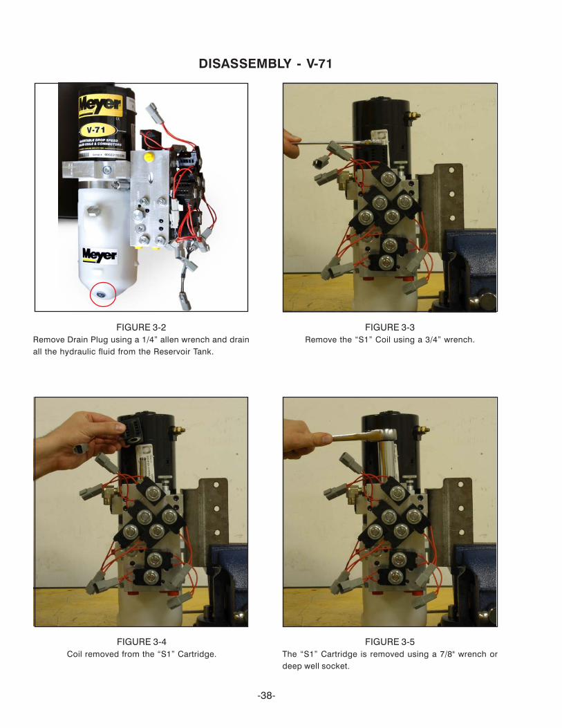
DISASSEMBLY - V-71
FIGURE 3-2Remove Drain Plug using a 1/4” allen wrench and drainall the hydraulic fluid from the Reservoir Tank.
FIGURE 3-3Remove the “S1” Coil using a 3/4” wrench.
FIGURE 3-4Coil removed from the “S1” Cartridge.
FIGURE 3-5The “S1” Cartridge is removed using a 7/8" wrench ordeep well socket.
-38-

FIGURE 3-6The “S1” Cartridge is removed. Clean by soakingcartridge in cleaning solvent.
FIGURE 3-7Coil removed from the “S2” Cartridge.
FIGURE 3-8The “S2” Cartridge is removed using a 7/8" wrench ordeep well socket.
FIGURE 3-9The “S2” Cartridge is removed. Clean by soakingcartridge in cleaning solvent.
-39-
DISASSEMBLY - V-71
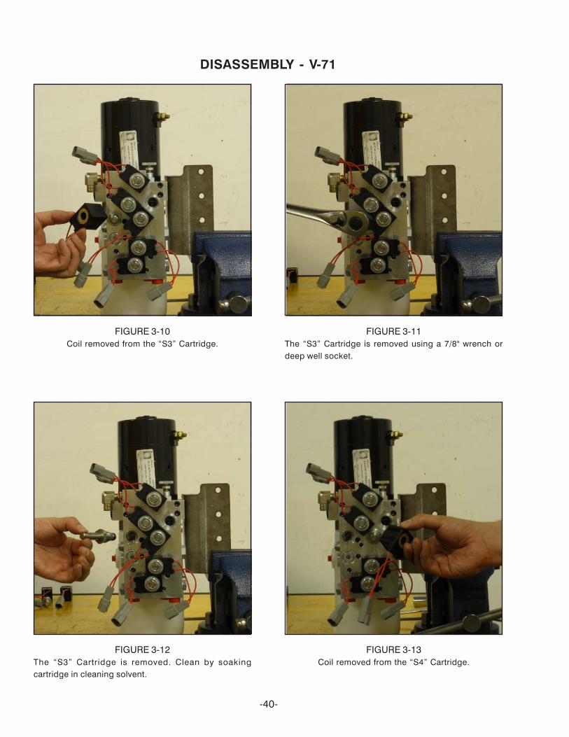
FIGURE 3-10Coil removed from the “S3” Cartridge.
FIGURE 3-11The “S3” Cartridge is removed using a 7/8" wrench ordeep well socket.
FIGURE 3-12The “S3” Cartridge is removed. Clean by soakingcartridge in cleaning solvent.
FIGURE 3-13Coil removed from the “S4” Cartridge.
-40-
DISASSEMBLY - V-71

FIGURE 3-14The “S4” Cartridge is removed using a 7/8" wrench ordeep well socket.
FIGURE 3-15The “S4” Cartridge is removed. Clean by soakingcartridge in cleaning solvent.
DISASSEMBLY - V-71
FIGURE 3-16Coil removed from the “S5” Cartridge.
FIGURE 3-17The “S5” Cartridge is removed using a 7/8" wrench ordeep well socket.
-41-

DISASSEMBLY - V-71
FIGURE 3-19Coil removed from the “S6” Cartridge.
FIGURE 3-18The “S5” Cartridge is removed. Clean by soakingcartridge in cleaning solvent.
FIGURE 3-20The “S6” Cartridge is removed using a 7/8" wrench ordeep well socket.
FIGURE 3-21The “S6” Cartridge is removed. Clean by soakingcartridge in cleaning solvent.
-42-

DISASSEMBLY - V-71
-43-
FIGURE 3-22Coil removed from the “S7” Cartridge.
FIGURE 3-23The “S7” Cartridge is removed using a 7/8" wrench ordeep well socket.
FIGURE 3-24The “S7” Cartridge is removed. Clean by soakingcartridge in cleaning solvent.
FIGURE 3-25Coil removed from the “S8” Cartridge.

j
DISASSEMBLY - V-71
-44-
FIGURE 3-26The “S8” Cartridge is removed using a 7/8" wrench ordeep well socket.
FIGURE 3-27The “S8” Cartridge is removed. Clean by soakingcartridge in cleaning solvent.
FIGURE 3-28The lower adjustment assembl is removed. Clean bysoaking in cleaning solvent.
FIGURE 3-29Use a 1/4” allen wrench to remove the check valve cap.

DISASSEMBLY - V-71
-45-
y g g g
FIGURE 3-30Remove the check valve cap.
FIGURE 3-31Remove the check valve spring.
FIGURE 3-32Remove the check valve poppet.
FIGURE 3-33Repeart 3-30 thru 3-32 for the 4 check valves on eitherside of the block and 1 on top of the block.

DISASSEMBLY - V-71
FIGURE 3-35Remove the right plow wing dual PO check valve. Cleanby soaking cartridge in cleaning solvent.
FIGURE 3-36Repeat 3-34 and 3-35 for left plow wing dual PO checkvalve.
FIGURE 3-37Using a 9/16” wrench loosen the Relif Valve Jam Nut.
-46-
FIGURE 3-34Use a 7/8” wrench to remove the right plow wing dualPO check valve.
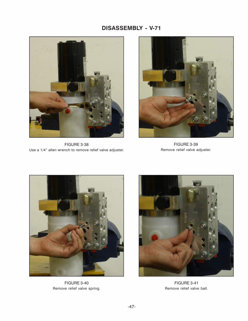
FIGURE 3-38Use a 1/4” allen wrench to remove relief valve adjuster.
DISASSEMBLY - V-71
FIGURE 3-39Remove relief valve adjuster.
FIGURE 3-40Remove relief valve spring.
FIGURE 3-41Remove relief valve ball.
-47-

FIGURE 3-42Repeat 3-37 thru 3-41 for the remaining 3 relief valveson the left side of the block and 2 more relief valves onthe right side. Note: Left picture top 2 relief valves set to3000 P.S.I., bottom 2 on both left and right pictures set to2900 P.S.I. Tighten adjuster to increase pressure.
DISASSEMBLY - V-71
FIGURE 3-43Use a 3/4” wrench to loosen jam nut and a 1/4” allenwrench to remove pump pressure adjusting screw.
FIGURE 3-44Remove pump relief valve spring.
FIGURE 3-45Remove pump relief valve ball.
-48-
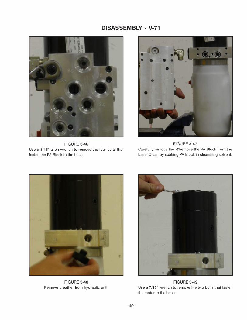
FIGURE 3-46Use a 3/16” allen wrench to remove the four bolts thatfasten the PA Block to the base.
DISASSEMBLY - V-71
FIGURE 3-47Carefully remove the R%emove the PA Block from thebase. Clean by soaking PA Block in cleanining solvent.
FIGURE 3-48Remove breather from hydraulic unit.
-49-
FIGURE 3-49Use a 7/16” wrench to remove the two bolts that fastenthe motor to the base.
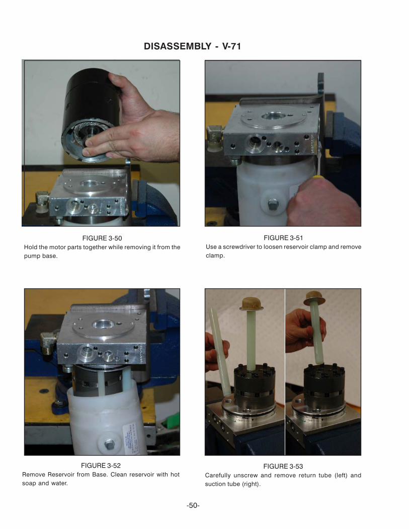
FIGURE 3-50Hold the motor parts together while removing it from thepump base.
DISASSEMBLY - V-71
FIGURE 3-51Use a screwdriver to loosen reservoir clamp and removeclamp.
FIGURE 3-53Carefully unscrew and remove return tube (left) andsuction tube (right).
-50-
FIGURE 3-52Remove Reservoir from Base. Clean reservoir with hotsoap and water.
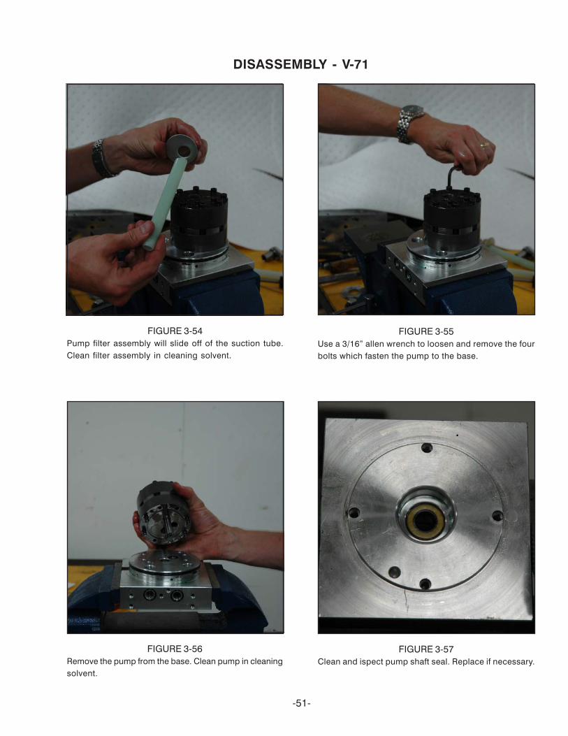
FIGURE 3-55Use a 3/16” allen wrench to loosen and remove the fourbolts which fasten the pump to the base.
DISASSEMBLY - V-71
FIGURE 3-56Remove the pump from the base. Clean pump in cleaningsolvent.
FIGURE 3-57Clean and ispect pump shaft seal. Replace if necessary.
-51-
FIGURE 3-54Pump filter assembly will slide off of the suction tube.Clean filter assembly in cleaning solvent.
-52-
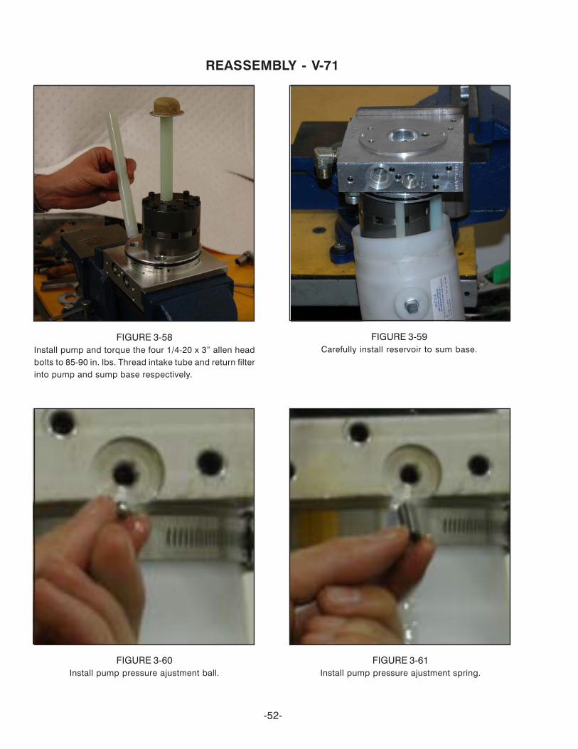
FIGURE 3-58Install pump and torque the four 1/4-20 x 3” allen headbolts to 85-90 in. lbs. Thread intake tube and return filterinto pump and sump base respectively.
REASSEMBLY - V-71
FIGURE 3-59Carefully install reservoir to sum base.
FIGURE 3-60Install pump pressure ajustment ball.
FIGURE 3-61Install pump pressure ajustment spring.

-53-
FIGURE 3-62Install the pump pressure adjustment assembly screw.The adjustment is achieved by turning the screwclockwise to increase pump pressure and counterclockwise to decrease pump pressure. Properadjustment is 2000 PSI.
REASSEMBLY - V-71
FIGURE 3-63Replace the two o-rings and install the PA Valve BlockAssembly to the Sump Base. Torqu the four 1/4-20 x 3-1/2” allen head bolts to 85-90 in. lbs.
FIGURE 3-64Install left dual PO check valves with caps using a 7/8”wrench.
FIGURE 3-65Install right dual PO check valves with caps using a7/8” wrench.

-54-
FIGURE 3-66Install left and right 2900 PSI. reliev valve assembliesasnd tighten using a 7/8” wrench. (circled in red).
FIGURE 3-67IInstall left and right 3000 PSI. reliev valve assembliesasnd tighten using a 7/8” wrench.
FIGURE 3-68Install lower adjust assembly using a 7/8” wrench. Loweradjustment setting is achieved by loosening the jam nutand turn the adjustment knob clockwise to slow how fastthe plow drops to the ground or turn the adjument screwcounter clockwise to make the plow drop faster.
FIGURE 3-69Install all the solenoid valves into their proper location.
REASSEMBLY - V-71

-55-
ELECTRICAL SPECIFICATIONSMOTOR
Under load (pump operating in relief)NOTE: Do not operate motor continuously for more than 5 seconds.Applied Voltage 12 Volts DCMax. Current Draw 250 Amperes
SOLENOID VALVES “S1”, “S2”, “S3”, ”S4”, “S5”, “S6”, “S7” & “S8”Applied Voltage 12 Volts DCCurrent Draw 1.9 AmperesNominal resistance (ohm meter lead connected to coil lead) 8.0 ohms ± 10%.
MOTOR SOLENOIDApplied Voltage 12 Volts DCMax. Current Draw 5 Amperes
Nominal resistance (ohm meter lead connected to coil lead, other meter lead connected to metal foot) 2.65 to4.5 ohms.
PUMP - Pressure Output2000 P.S.I.
CROSSOVER RELIEF VALVEOpening Pressure 2900/3000 P.S.I.
HYDRAULIC FLUID CAPACITYNOTE :1 Quart = 32 Fluid OuncesModel V-71Unit 1.55 qt., 0 oz. (50 oz.)Hoses, Lift Cylinder & D.A. 17 oz.Total 2 qt., 3 oz. (67 oz.)
HYDRAULIC SPECIFICATIONS

V-71power unit
service manual
© 2012 Printed in the U.S.A.
Meyer Products LLC18513 Euclid Ave. • Cleveland, Ohio 44112-1084
Phone 486-1313 (Area Code 216)www.meyerproducts.com• email [email protected]