v ezs330-350 gb
TRANSCRIPT

Operating instructions
50468397
EZS 330/350 / XL
G
04.06 -
04.06
0108
.GB
ForewordThe present ORIGINAL OPERATING INSTRUCTIONS are designed to providesufficient instruction for the safe operation of the industrial truck. The information isprovided clearly and concisely. The chapters are arranged by letter. Each chapterstarts with page 1. The page identification consists of a chapter letter and a pagenumber.For example: Page B 2 is the second page in chapter B.
The operating instructions detail different truck models. When operating and servicingthe truck, make sure that the instructions apply to your truck model.
Safety instructions and important explanations are indicated by the followinggraphics:
F Used before safety instructions which must be observed to avoid danger topersonnel.
M Used before notices which must be observed to avoid material damage.
Z Used before notices and explanations.
t Used to indicate standard equipment.
o Used to indicate optional equipment.
Our trucks are subject to ongoing development. Jungheinrich reserves the right toalter the design, equipment and technical features of the truck. No guarantee ofparticular features of the truck should therefore be inferred from the present operatinginstructions.
Copyright
Copyright of these operating instructions remains with JUNGHEINRICH AG.
Jungheinrich Aktiengesellschaft
Am Stadtrand 3522047 Hamburg - GERMANY
Telephone: +49 (0) 40/6948-0
www.jungheinrich.com

0108
.GB
0108
.GB
I 1
0205
.GB
Table of ContentsA Correct use and application
B Truck Description
1 Application ........................................................................................... B 12 Assemblies ......................................................................................... B 22.1 EN norms ............................................................................................ B 32.2 Conditions of use ................................................................................ B 33 Standard Version Specifications ......................................................... B 43.1 Performance data for standard trucks ................................................. B 43.2 Dimensions ......................................................................................... B 44 Identification points and data plates .................................................... B 64.1 Truck data plate .................................................................................. B 7
C Transport and Commissioning
1 Lifting by crane .................................................................................... C 12 Securing the truck during transport ..................................................... C 13 Using the truck for the first time .......................................................... C 24 Operating the truck without its own drive system ................................ C 3
D Battery Maintenance, Charging & Replacement
1 Safety regulations for handling acid batteries ..................................... D 12 Battery types ....................................................................................... D 23 Exposing the battery ........................................................................... D 34 Charge the battery .............................................................................. D 45 Battery removal and installation .......................................................... D 5
0205
.GB
I 2
E Operation
1 Safety Regulations for the Operation of Forklift Trucks ...................... E 12 Controls and Displays ......................................................................... E 23 Starting up the truck ............................................................................ E 44 Industrial Truck Operation ................................................................... E 54.1 Safety regulations for truck operation ................................................. E 54.2 Travel, Steering, Braking ..................................................................... E 64.3 Pedestrian operation (o) .................................................................... E 94.4 Coupling Types ................................................................................... E 104.5 Travelling with trailers ......................................................................... E 114.6 Seat o (XL only) ................................................................................. E 124.7 Parking the truck securely ................................................................... E 125 Display instrument (CANDIS) (o) ....................................................... E 135.1 Operating hours display ...................................................................... E 135.2 Power up test ...................................................................................... E 146 Keypad (CANCODE) (o) .................................................................... E 156.1 Code Lock ........................................................................................... E 156.2 Travel programs .................................................................................. E 176.3 Parameters .......................................................................................... E 176.4 Parameter Settings ............................................................................. E 186.5 Travel parameters ............................................................................... E 227 Troubleshooting .................................................................................. E 27
F Industrial Truck Maintenance
1 Operational safety and environmental protection ................................ F 12 Maintenance Safety Regulations ........................................................ F 13 Servicing and inspection ..................................................................... F 34 Maintenance checklist ......................................................................... F 45 Lubrication Schedule ........................................................................... F 65.1 Consumables ...................................................................................... F 76 Maintenance Instructions .................................................................... F 86.1 Preparing the truck for maintenance and repairs ................................ F 86.2 Tightening the wheel nuts ................................................................... F 86.3 Remove the front panel ....................................................................... F 96.4 Checking electrical fuses .................................................................... F 106.5 Recommissioning ................................................................................ F 117 Decommissioning the industrial truck .................................................. F 117.1 Prior to decommissioning: ................................................................... F 117.2 During decommissioning: .................................................................... F 117.3 Returning the truck to operation after decommissioning ..................... F 128 Safety checks to be performed at regular intervals and following
any unusual incidents (D: Accident prevention check according to BGV D27 ......................................................................................... F 12
9 Final de-commissioning, disposal ....................................................... F 12

1
0506
.GB
Appendix
JH Traction Battery Operating Instructions
Z These operating instructions apply only to Jungheinrich battery models. If usinganother brand, refer to the manufacturer's operating instructions.
1
0506
.GB
Appendix
JH Traction Battery Operating Instructions
Z These operating instructions apply only to Jungheinrich battery models. If usinganother brand, refer to the manufacturer's operating instructions.

0506
.GB
2
0506
.GB
2
A 1
0406
.GB
A Correct use and application
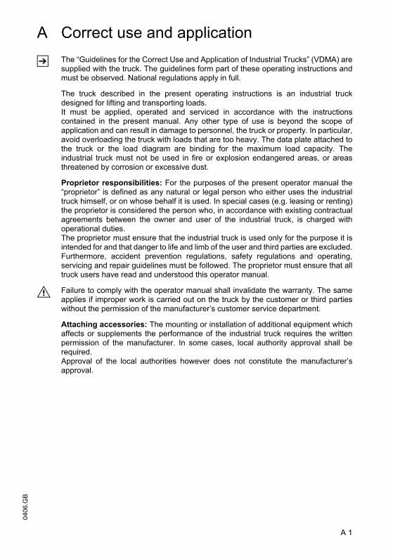
Z The “Guidelines for the Correct Use and Application of Industrial Trucks” (VDMA) aresupplied with the truck. The guidelines form part of these operating instructions andmust be observed. National regulations apply in full.
The truck described in the present operating instructions is an industrial truckdesigned for lifting and transporting loads.It must be applied, operated and serviced in accordance with the instructionscontained in the present manual. Any other type of use is beyond the scope ofapplication and can result in damage to personnel, the truck or property. In particular,avoid overloading the truck with loads that are too heavy. The data plate attached tothe truck or the load diagram are binding for the maximum load capacity. Theindustrial truck must not be used in fire or explosion endangered areas, or areasthreatened by corrosion or excessive dust.
Proprietor responsibilities: For the purposes of the present operator manual the“proprietor” is defined as any natural or legal person who either uses the industrialtruck himself, or on whose behalf it is used. In special cases (e.g. leasing or renting)the proprietor is considered the person who, in accordance with existing contractualagreements between the owner and user of the industrial truck, is charged withoperational duties.The proprietor must ensure that the industrial truck is used only for the purpose it isintended for and that danger to life and limb of the user and third parties are excluded.Furthermore, accident prevention regulations, safety regulations and operating,servicing and repair guidelines must be followed. The proprietor must ensure that alltruck users have read and understood this operator manual.
M Failure to comply with the operator manual shall invalidate the warranty. The sameapplies if improper work is carried out on the truck by the customer or third partieswithout the permission of the manufacturer’s customer service department.
Attaching accessories: The mounting or installation of additional equipment whichaffects or supplements the performance of the industrial truck requires the writtenpermission of the manufacturer. In some cases, local authority approval shall berequired. Approval of the local authorities however does not constitute the manufacturer’sapproval.
A 1
0406
.GB
A Correct use and application
Z The “Guidelines for the Correct Use and Application of Industrial Trucks” (VDMA) aresupplied with the truck. The guidelines form part of these operating instructions andmust be observed. National regulations apply in full.
The truck described in the present operating instructions is an industrial truckdesigned for lifting and transporting loads.It must be applied, operated and serviced in accordance with the instructionscontained in the present manual. Any other type of use is beyond the scope ofapplication and can result in damage to personnel, the truck or property. In particular,avoid overloading the truck with loads that are too heavy. The data plate attached tothe truck or the load diagram are binding for the maximum load capacity. Theindustrial truck must not be used in fire or explosion endangered areas, or areasthreatened by corrosion or excessive dust.
Proprietor responsibilities: For the purposes of the present operator manual the“proprietor” is defined as any natural or legal person who either uses the industrialtruck himself, or on whose behalf it is used. In special cases (e.g. leasing or renting)the proprietor is considered the person who, in accordance with existing contractualagreements between the owner and user of the industrial truck, is charged withoperational duties.The proprietor must ensure that the industrial truck is used only for the purpose it isintended for and that danger to life and limb of the user and third parties are excluded.Furthermore, accident prevention regulations, safety regulations and operating,servicing and repair guidelines must be followed. The proprietor must ensure that alltruck users have read and understood this operator manual.
M Failure to comply with the operator manual shall invalidate the warranty. The sameapplies if improper work is carried out on the truck by the customer or third partieswithout the permission of the manufacturer’s customer service department.
Attaching accessories: The mounting or installation of additional equipment whichaffects or supplements the performance of the industrial truck requires the writtenpermission of the manufacturer. In some cases, local authority approval shall berequired. Approval of the local authorities however does not constitute the manufacturer’sapproval.

B 1
0406
.GB
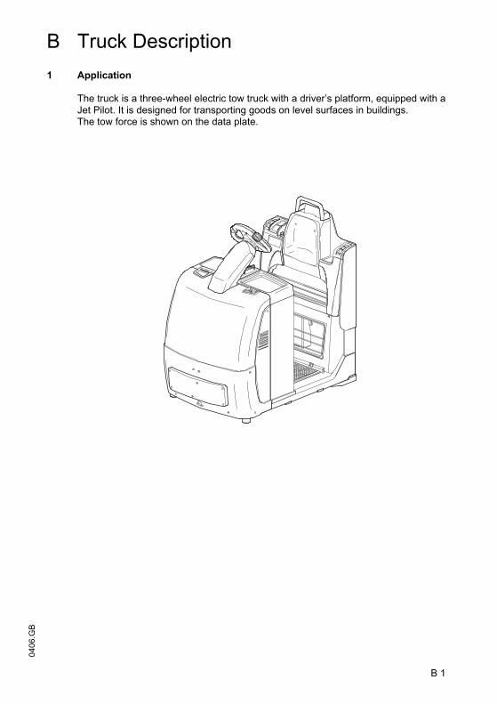
B Truck Description1 Application
The truck is a three-wheel electric tow truck with a driver’s platform, equipped with aJet Pilot. It is designed for transporting goods on level surfaces in buildings. The tow force is shown on the data plate.
B 1
0406
.GB
B Truck Description1 Application
The truck is a three-wheel electric tow truck with a driver’s platform, equipped with aJet Pilot. It is designed for transporting goods on level surfaces in buildings. The tow force is shown on the data plate.

0406
.GB
B 2
2 Assemblies
Item Description Item Description1 t Front panel 8 o Reverse “pedestrian
operation” switch2 t Battery panel 9 o Stop button3 t Jet Pilot 10 o Forward “pedestrian / walk-
along operation” button4 t Main switch / isolator
(emergency disconnect)11 o Trailer coupling
5 t Controller 12 t Storage compartment6 o CANCODE
keypad13 t Drive wheel
7 t Key switch o Headlight (not shown)o Strobe (not shown)
t = Standard equipment o = Optional Equipment
1 2 3 4 5 6 7
89
10
11
12
13

B 3
0406
.GB
2.1 EN norms
Noise level: 66 dB(A)
in accordance with EN 12053 as harmonized withISO 4871.
Z The noise emission level is calculated in accordance with standard procedures andtakes into account the noise level when travelling, lifting and when idle. The noiselevel is measured at the driver’s ear.
Vibration: 0.94 m/s2
in accordance with EN 13059
Z The vibration acceleration acting on the body in the operating position is, inaccordance with standard procedures, the linearly integrated, weighted accelerationin the vertical direction. It is calculated when travelling over bumps at constant speed.
Electromagnetic Compatibility (
The manufacturer confirms that equipment complies withtolerance levels for electromagnetic emissions andresistance as well as static electricity discharge testing inaccordance with EN 12895 including the normativeprocedures contained therein.
Z No changes to electric or electronic components or their arrangement may be madewithout the written agreement of the manufacturer.
2.2 Conditions of use
Ambient temperature- during operation -10°C to 40 °C
Z Special equipment and authorisation are required if the truck is to be constantly usedin conditions of extreme temperature or air humidity fluctuations.

0406
.GB
B 4
3 Standard Version Specifications
Z Technical specification details in accordance with VDI 2198. Technical modificationsand additions reserved.
3.1 Performance data for standard trucks
3.2 Dimensions
1) Level, rolling resistance 200N/t
2) JetPilot height
3) Total length excluding coupling, as different coupling versions are available
Description EZS 330 EZS 350 EZS 330 XL EZS 350 XLQ Tow capacity 1) 3000 5000 3000 5000 kgF Rated tow force 600 1000 600 1000 N
Description EZS 330 EZS 350 EZS 330 XL EZS 350 XLNet weight 1066 1066 1201 1201 kgAxle load w.o. load front/rear 514/552 514/552 635/566 635/566 kg
h7 Height 132 132 142 142 mmh14 Tiller height in travel
position 2) 1342 1342 1387 1387 mm
h10 Coupling height 158 158 158 158 mml1 Overall length3) 1260 1260 1427 1427 mmb1 Overall width 810 810 810 810 mmb11 Track width, rear 490 490 490 490 mmy Wheel base 920 920 1087 1087 mm
m2 Centre wheelbase ground clearance 45 45 45 45 mm
Wa Turning radius 1160 1160 1320 1320 mmTravel speed w / w.o. load 8,5/12,5 5,0/8,0 8,5/12,5 5,0/8,0 km/h
Tow force without load s2 60 min 600 1000 600 1000 N
Max. tow force without load s2 5 min 3000 3500 3000 3500 N
Drive motor, output at s2 60 min 2.5 2.5 2.5 2.5 kW
Battery voltage, rated capacity k5
24/420 (450)
24/420 (450)
24/560 (600)
24/560 (600) V/Ah
Battery weight 370 370 370/450 370/450 kg

B 5
0406
.GB4) Rated tow force
a2
a2 Wa
y
1335
l1
b11
b1
h14
m2
h10
h7
B 5
0406
.GB
4) Rated tow force
a2
a2 Wa
y
1335
l1
b11
b1
h14
m2
h10
h7

0406
.GB
B 6
4 Identification points and data plates
Item Description14 Truck data plate15 “Caution, pushbutton operation” warning16 Accident prevention inspection label (Donly)17 Warning: Risk of trapping when reversing18 Attachment point of hooks for transportation by crane (inside)
“Read operating instructions” warning
XXXXXXXXXXXXXXXXXX
XXXXXXXXXXXXXXXXXX
XXXXXXXXXXXXXXXXXXXXXX
XXXXXXXXXXXXXXXXXXXXXXXX
XXXXXXXXXXXXXXXXXX
XXXXXXXXXXXXXXXXXXXX
XXXXXXXXXXXXXXXXXXXXXXXXXXXX
XXXXXXXXXXXXXXXXXX
XXXXXXXXXXXXXXXXXXXX
XXXXXXXXXXXXXXXXXXXXXXXXXX
XXXXXXXXXXXXXXXXXX
XXXXXXXXXXXXXXXXXX
XXXXXXXXXXXXXX
12 11 10 9 8 7 6 5 4 3
2 1
2000
14
15
16
18
17

B 7
0406
.GB
4.1 Truck data plate
Z For any queries relating to the truck or spare part orders, please state the truck serialno. (22).
Item Description19 Max. supporting force (kg)20 Net weight w.o. battery (kg)21 Min./max. battery weight (kg)22 Manufacturer23 Customer no.24 Year of manufacture25 Rated tow force 5 min. in N26 Output (kW)27 Order no.28 Battery: Voltage (V)29 Rated tow force 60 min. in N30 Serial no.31 Type32 Manufacturer’s logo
XXXXXXXXXXXXXXXXXX
XXXXXXXXXXXXXXXXXX
XXXXXXXXXXXXXXXXXXXXXX
XXXXXXXXXXXXXXXXXXXXXXXX
XXXXXXXXXXXXXXXXXX
XXXXXXXXXXXXXXXXXXXX
XXXXXXXXXXXXXXXXXXXXXXXXXXXX
XXXXXXXXXXXXXXXXXX
XXXXXXXXXXXXXXXXXXXX
XXXXXXXXXXXXXXXXXXXXXXXXXX
XXXXXXXXXXXXXXXXXX
XXXXXXXXXXXXXXXXXX
XXXXXXXXXXXXXX
XXXXXXXXXXXXXXXXXX
19
2021
22
23242526
27
28293031
32

0406
.GB
B 8
0406
.GB
B 8
C 1
0406
.GB
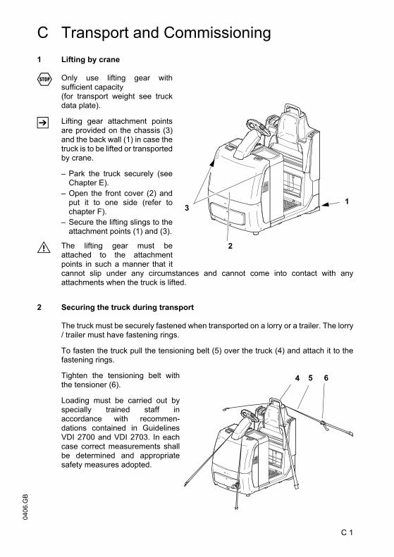
C Transport and Commissioning1 Lifting by crane
F Only use lifting gear withsufficient capacity (for transport weight see truckdata plate).
Z Lifting gear attachment pointsare provided on the chassis (3)and the back wall (1) in case thetruck is to be lifted or transportedby crane.
– Park the truck securely (seeChapter E).
– Open the front cover (2) andput it to one side (refer tochapter F).
– Secure the lifting slings to theattachment points (1) and (3).
M The lifting gear must beattached to the attachmentpoints in such a manner that itcannot slip under any circumstances and cannot come into contact with anyattachments when the truck is lifted.
2 Securing the truck during transport
The truck must be securely fastened when transported on a lorry or a trailer. The lorry/ trailer must have fastening rings.
To fasten the truck pull the tensioning belt (5) over the truck (4) and attach it to thefastening rings.
Tighten the tensioning belt withthe tensioner (6).
Loading must be carried out byspecially trained staff inaccordance with recommen-dations contained in GuidelinesVDI 2700 and VDI 2703. In eachcase correct measurements shallbe determined and appropriatesafety measures adopted.
1
2
3
4 5 6
C 1
0406
.GB
C Transport and Commissioning1 Lifting by crane
F Only use lifting gear withsufficient capacity (for transport weight see truckdata plate).
Z Lifting gear attachment pointsare provided on the chassis (3)and the back wall (1) in case thetruck is to be lifted or transportedby crane.
– Park the truck securely (seeChapter E).
– Open the front cover (2) andput it to one side (refer tochapter F).
– Secure the lifting slings to theattachment points (1) and (3).
M The lifting gear must beattached to the attachmentpoints in such a manner that itcannot slip under any circumstances and cannot come into contact with anyattachments when the truck is lifted.
2 Securing the truck during transport
The truck must be securely fastened when transported on a lorry or a trailer. The lorry/ trailer must have fastening rings.
To fasten the truck pull the tensioning belt (5) over the truck (4) and attach it to thefastening rings.
Tighten the tensioning belt withthe tensioner (6).
Loading must be carried out byspecially trained staff inaccordance with recommen-dations contained in GuidelinesVDI 2700 and VDI 2703. In eachcase correct measurements shallbe determined and appropriatesafety measures adopted.
1
2
3
4 5 6

0406
.GB
C 2
3 Using the truck for the first time
M Only operate the truck with battery current. Rectified AC current will damage theelectronic components. Cables connected to the battery (trailing cables) must be lessthan 6 meters in length.
To prepare the truck after delivery or after transport, proceed as follows:
– Check the truck for completion and satisfactory condition of the equipment.– Install battery (where required). Do not damage battery cables (see Chapter D).– Charge the battery (see Chapter D).– Commission the truck in accordance with instructions (see Chapter E).
Z When the truck is parked, the running surface of the tyres will flatten. The flatteningwill disappear after a short period of operation.

C 3
0406
.GB
4 Operating the truck without its own drive system
F This operating mode is not permitted when negotiating inclines and gradients.
If the truck has to be moved after a failure has rendered it immobile, proceed asfollows:
– Set the master switch to position “OFF”.– Set the key switch to position “OFF” (“0”) and remove the key.– Prevent the truck from rolling away.– Open battery cover (refer to chapter D).– Open the front cover (7) and put it to one side (see chapter F).– Slacken the lock nuts (8) and tighten the screws (9).
The brake is now released and the truck can move.
F On reaching your destination, ensure that the brake is restored to its initial state. Thetruck must never be parked with the brakes released.
– Loosen the screws (9) by approx. 5 mm and lock by tightening the lock nuts (8).
The brake is now applied again.
– Refit the front cover (7).
7
8
9

0406
.GB
C 4
0406
.GB
C 4

D 1
0406
.GB
D Battery Maintenance, Charging &Replacement
1 Safety regulations for handling acid batteries
Park the truck securely before carrying out any work on the batteries (see Chapter E).
Maintenance personnel: Batteries may only be charged, serviced or replaced bytrained personnel. The present operator manual and the manufacturer’s instructionsconcerning batteries and charging stations must be observed when carrying out thework.
Fire protection: Smoking and naked flames must be avoided when working withbatteries Wherever a truck is parked for charging there shall be no inflammablematerial or operating fluids capable of creating sparks within 2 metres around thetruck. The area must be well ventilated. Fire protection equipment must be provided.
Battery maintenance: The battery cell covers must be kept dry and clean. Theterminals and cable shoes must be clean, secure and have a light coating of dielectricgrease. Batteries with non insulated terminals must be covered with a non slipinsulation mat.
Battery Disposal: Batteries may only be disposed of in accordance with nationalenvironmental protection regulations or disposal laws. The manufacturer’s disposalinstructions must be followed.
M Before closing the battery cover make sure that the battery lead cannot be damaged.
F Batteries contain an acid solution which is poisonous and corrosive. Therefore,always wear protective clothing and eye protection when carrying out work onbatteries. Avoid all contact with battery acide.Should however clothing, skin or eyes come in contact with acid the affected partsshould be rinsed with plenty of clean water - where the skin or eyes are affected calla doctor immediately. Immediately neutralise any spilled battery acid.
M Only batteries with a sealed battery container may be used.
F The weight and dimensions of the battery have considerable affect on the operationalsafety of the truck. Battery equipment may only be replaced with the agreement of themanufacturer.
0406
.GB
D 2
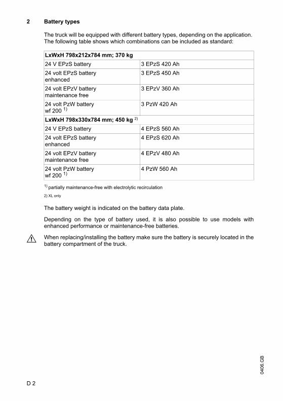
2 Battery types
The truck will be equipped with different battery types, depending on the application. The following table shows which combinations can be included as standard:
1) partially maintenance-free with electrolytic recirculation
2) XL only
The battery weight is indicated on the battery data plate.
Depending on the type of battery used, it is also possible to use models withenhanced performance or maintenance-free batteries.
M When replacing/installing the battery make sure the battery is securely located in thebattery compartment of the truck.
LxWxH 798x212x784 mm; 370 kg24 V EPzS battery 3 EPzS 420 Ah24 volt EPzS batteryenhanced
3 EPzS 450 Ah
24 volt EPzV battery maintenance free
3 EPzV 360 Ah
24 volt PzW batterywf 200 1)
3 PzW 420 Ah
LxWxH 798x330x784 mm; 450 kg 2)
24 V EPzS battery 4 EPzS 560 Ah 24 volt EPzS batteryenhanced
4 EPzS 620 Ah
24 volt EPzV battery maintenance free
4 EPzV 480 Ah
24 volt PzW batterywf 200 1)
4 PzW 560 Ah
0406
.GB
D 2
2 Battery types
The truck will be equipped with different battery types, depending on the application. The following table shows which combinations can be included as standard:
1) partially maintenance-free with electrolytic recirculation
2) XL only
The battery weight is indicated on the battery data plate.
Depending on the type of battery used, it is also possible to use models withenhanced performance or maintenance-free batteries.
M When replacing/installing the battery make sure the battery is securely located in thebattery compartment of the truck.
LxWxH 798x212x784 mm; 370 kg24 V EPzS battery 3 EPzS 420 Ah24 volt EPzS batteryenhanced
3 EPzS 450 Ah
24 volt EPzV battery maintenance free
3 EPzV 360 Ah
24 volt PzW batterywf 200 1)
3 PzW 420 Ah
LxWxH 798x330x784 mm; 450 kg 2)
24 V EPzS battery 4 EPzS 560 Ah 24 volt EPzS batteryenhanced
4 EPzS 620 Ah
24 volt EPzV battery maintenance free
4 EPzV 480 Ah
24 volt PzW batterywf 200 1)
4 PzW 560 Ah
D 3
0406
.GB
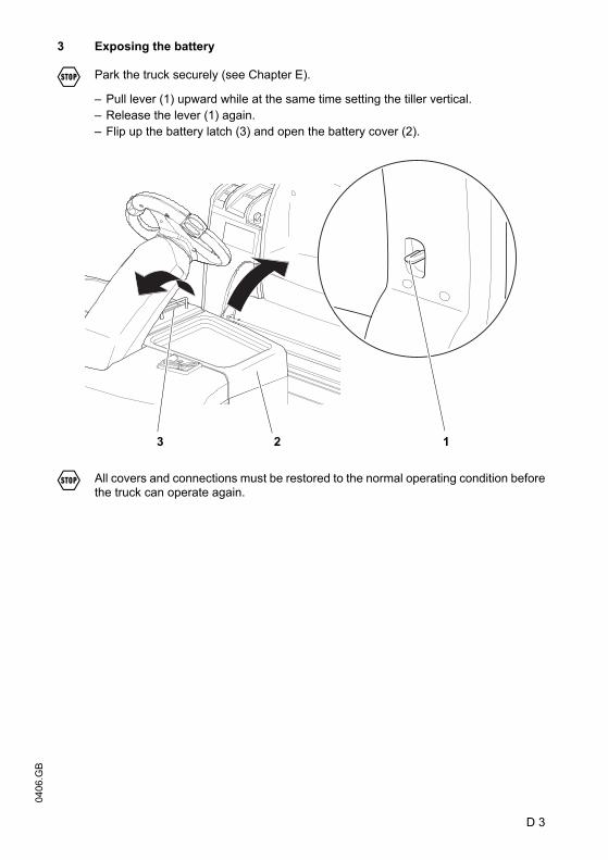
3 Exposing the battery
F Park the truck securely (see Chapter E).
– Pull lever (1) upward while at the same time setting the tiller vertical.– Release the lever (1) again.– Flip up the battery latch (3) and open the battery cover (2).
F All covers and connections must be restored to the normal operating condition beforethe truck can operate again.
123
D 3
0406
.GB
3 Exposing the battery
F Park the truck securely (see Chapter E).
– Pull lever (1) upward while at the same time setting the tiller vertical.– Release the lever (1) again.– Flip up the battery latch (3) and open the battery cover (2).
F All covers and connections must be restored to the normal operating condition beforethe truck can operate again.
123
0406
.GB
D 4
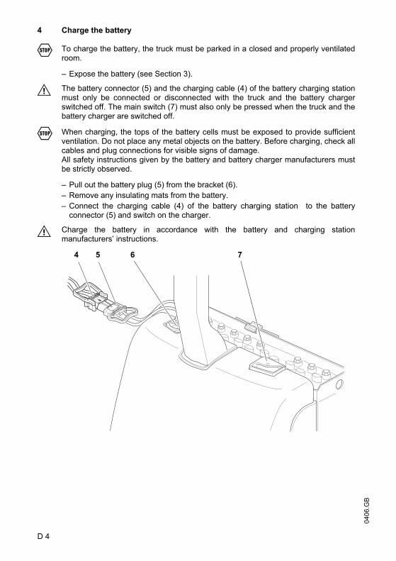
4 Charge the battery
F To charge the battery, the truck must be parked in a closed and properly ventilatedroom.
– Expose the battery (see Section 3).
M The battery connector (5) and the charging cable (4) of the battery charging stationmust only be connected or disconnected with the truck and the battery chargerswitched off. The main switch (7) must also only be pressed when the truck and thebattery charger are switched off.
F When charging, the tops of the battery cells must be exposed to provide sufficientventilation. Do not place any metal objects on the battery. Before charging, check allcables and plug connections for visible signs of damage.All safety instructions given by the battery and battery charger manufacturers mustbe strictly observed.
– Pull out the battery plug (5) from the bracket (6).– Remove any insulating mats from the battery.– Connect the charging cable (4) of the battery charging station to the battery
connector (5) and switch on the charger.
M Charge the battery in accordance with the battery and charging stationmanufacturers’ instructions.
4 5 6 7
0406
.GB
D 4
4 Charge the battery
F To charge the battery, the truck must be parked in a closed and properly ventilatedroom.
– Expose the battery (see Section 3).
M The battery connector (5) and the charging cable (4) of the battery charging stationmust only be connected or disconnected with the truck and the battery chargerswitched off. The main switch (7) must also only be pressed when the truck and thebattery charger are switched off.
F When charging, the tops of the battery cells must be exposed to provide sufficientventilation. Do not place any metal objects on the battery. Before charging, check allcables and plug connections for visible signs of damage.All safety instructions given by the battery and battery charger manufacturers mustbe strictly observed.
– Pull out the battery plug (5) from the bracket (6).– Remove any insulating mats from the battery.– Connect the charging cable (4) of the battery charging station to the battery
connector (5) and switch on the charger.
M Charge the battery in accordance with the battery and charging stationmanufacturers’ instructions.
4 5 6 7

D 5
0406
.GB
5 Battery removal and installation
F The truck must be parked on level ground. To prevent short circuits, batteries withexposed terminals or connectors must be covered with a rubber mat. Place thebattery connector or the battery cable in such a way that they will not get caught onthe truck when the battery is withdrawn.
M When transporting batteries using a crane, ensure that the crane is of adequatecapacity (the battery weight is indicated on the battery data plate on the batterycontainer). The lifting gear must exert a vertical pull so that the battery container isnot compressed. Attach the hooks to the attachment points (8) in such a way that thelifting gear, when slack, cannot collapse on the battery cells.
– Expose the battery (see Section 3).– Pull out the battery plug (10) from the bracket.– Flip back the battery locking mechanism (9).– Using crane lifting gear, lift the battery (11) slowly and carefully out of the truck.
The battery can optionally be removed from the side. To do this, pull the battery outat the side onto the battery replacement trolley.
F Do not put your fingers between the truck frame and the battery.
F Follow the operating instructions of the battery replacement trolley manufacturer!
Installation is in the reverse order of removal. When reinstalling the battery, note therequired installation position and make sure the battery is connected correctly.
F After installing the battery check all cables and plug connections for visible signs ofdamage.The battery must be securely fixed in the truck to avoid damage arising fromaccidental movement. After each replacement ensure that the battery is preventedfrom sliding, by flipping the battery locking mechanism (9) back into the recess.The battery cover must be firmly closed.
8
9 10 11

0406
.GB
D 6
0406
.GB
D 6

E 1
0406
.GB
E Operation1 Safety Regulations for the Operation of Forklift Trucks
Driver authorisation The forklift truck may only be used by suitably trainedpersonnel, who have demonstrated to the proprietor or his representative that theycan drive and handle loads and have been authorised to operate the truck by theproprietor or his representative.
Driver’s rights, obligations and responsibilities: The driver must be informed ofhis duties and responsibilities and be instructed in the operation of the truck and shallbe familiar with the operator manual. The driver shall be afforded all due rights. Safety shoes must be worn for pedestrian operated trucks.
Unauthorised Use of Truck: The driver is responsible for the truck during the timeit is in use. The drive must prevent unauthorised persons from driving or operating thetruck. Do not carry passengers.
Damage and Faults: The supervisor must be immediately informed of any damageor faults to the forklift truck or attachment. Trucks which are unsafe for operation (e.g.wheel or brake problems) must not be used until they have been rectified.
Repairs: The driver must not carry out any repairs or alterations to the forklift truckwithout the necessary training and authorisation to do so. The driver must neverdisable or adjust safety mechanisms or switches.
Hazardous area: A hazardous area is defined as the area in which people are at riskfrom the truck movement, the load handler (e.g. attachments) or the load itself. Thisalso includes areas which can be reached by falling loads or by the trailer veering.
F Unauthorised persons must be kept away from the hazardous area. Where there isdanger to personnel, a warning must be sounded with sufficient notice. Ifunauthorised personnel are still within the hazardous area the truck shall be broughtto a halt immediately.
Safety Devices and Warning Signs: Safety devices, warning signs and warninginstructions shall be strictly observed.

0406
.GB
E 2
2 Controls and Displays
Item Control / Display Function1 Jet Pilot t Steers the truck.2 Brake button t The truck brakes at the maximum possible
deceleration rate until it comes to a halt.3 “Horn” button t Triggers a warning signal.4 Controller t Controls the direction of travel as well as
the travel speed.5 Forward “pedestrian / walk-
along operation” buttono Travel starts in pedestrian mode in the
forward direction (V) (slow travel).
6 Stop button o The electrical functions are cut out and the truck automatically brakes.
7 Reverse “pedestrian operation” button
o Travel starts in pedestrian mode in the reverse direction (R) (slow travel).
8 Display instrument (CANDIS)
o Hourmeter.Displays battery capacity.Displays travel parameters and service indicators.Shows the service hours completed by the truck.
9 CANCODE keypad
o Code settings. Release and select the travel programs.Enter travel parameters.
Code Lock o Replaces the key switch.Switches control voltage on and off.Releases the truck functions.
10 Key switch t Switches the truck on and off.Removing the key prevents the truck from being switched on by unauthorised personnel.
11 Tiller adjustment t The tiller can be set to the required position.
12 Trailer coupling o For towed load13 Platform t – released (without load): Travel inhibited,
or truck decelerates.– actuated (with load): Travel released.
14 Main switch / isolator (emergency disconnect)
t The circuit is interrupted, all electrical functions are cut out and the truck automatically brakes.
t = Standard equipment o = Optional Equipment

E 3
0406
.GB
1
2
3
4 5 6 7 8 9 10
11
12567
1314
E 3
0406
.GB
1
2
3
4 5 6 7 8 9 10
11
12567
1314
0406
.GB
E 4
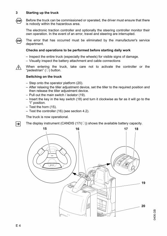
3 Starting up the truck
F Before the truck can be commissioned or operated, the driver must ensure that thereis nobody within the hazardous area.
The electronic traction controller and optionally the steering controller monitor theirown operation. In the event of an error, travel and steering are interrupted.
F The error that has occurred must be eliminated by the manufacturer's servicedepartment.
Checks and operations to be performed before starting daily work
– Inspect the entire truck (especially the wheels) for visible signs of damage.– Visually inspect the battery attachment and cable connections
M When entering the truck, take care not to activate the controller or the“pedestrian” (o) button.
Switching on the truck
– Step onto the operator platform (20).– After relaxing the tiller adjustment device, set the tiller to the required position and
then release the tiller adjustment device.– Pull out the main switch / isolator (19).– Insert the key in the key switch (18) and turn it clockwise as far as it will go to the
“I” position.– Test the horn (15).– Test the controller (16) (see section 4.2).
The truck is now operational.
Z The display instrument (CANDIS (17/(o)) shows the available battery capacity.15 16 17 18
19
20
0406
.GB
E 4
3 Starting up the truck
F Before the truck can be commissioned or operated, the driver must ensure that thereis nobody within the hazardous area.
The electronic traction controller and optionally the steering controller monitor theirown operation. In the event of an error, travel and steering are interrupted.
F The error that has occurred must be eliminated by the manufacturer's servicedepartment.
Checks and operations to be performed before starting daily work
– Inspect the entire truck (especially the wheels) for visible signs of damage.– Visually inspect the battery attachment and cable connections
M When entering the truck, take care not to activate the controller or the“pedestrian” (o) button.
Switching on the truck
– Step onto the operator platform (20).– After relaxing the tiller adjustment device, set the tiller to the required position and
then release the tiller adjustment device.– Pull out the main switch / isolator (19).– Insert the key in the key switch (18) and turn it clockwise as far as it will go to the
“I” position.– Test the horn (15).– Test the controller (16) (see section 4.2).
The truck is now operational.
Z The display instrument (CANDIS (17/(o)) shows the available battery capacity.15 16 17 18
19
20

E 5
0406
.GB
4 Industrial Truck Operation
4.1 Safety regulations for truck operation
Travel routes and work areas: Only use lanes and routes specifically designated fortruck traffic. Unauthorised third parties must stay away from work areas. Loads mustonly be stored in places specially designated for this purpose.
Travel conduct: The driver must adapt the travel speed to local conditions. The truckmust be driven at slow speed when negotiating bends or narrow passageways, whenpassing through swing doors and at blind spots. The driver must always observe anadequate braking distance between the forklift truck and the vehicle in front and mustbe in control of the truck at all times. Abrupt stopping (except in emergencies), rapidU turns and overtaking at dangerous or blind spots are not permitted. It is forbiddento lean out of or reach beyond the working and operating area.
Travel visibility: The driver must look in the direction of travel and must always havea clear view of the route ahead. The truck must travel with the load at the rear. If thisis not possible, e.g. when shunting, the driver must ensure that the shunting area isfree. If the driver does not have a clear view, a second person must act as a lookoutfor the shunting area.
Negotiating slopes and inclines: Negotiating slopes or inclines is only permitted ifsuch roads are clean and have a non-slip surface and providing such journeys aresafely undertaken in accordance with the technical specifications for the truck inquestion. The industrial truck must not be turned, operated at an angle or parked oninclines or slopes. Inclines must only be negotiated at slow speed, with the driverready to brake at any moment.
Negotiating lifts and docks: Lifts and docks must only be used if they have sufficientcapacity, are suitable for driving on and authorised for truck traffic by the owner. Thedriver must satisfy himself of the above before entering these areas. The truck mustenter lifts with the load in front and must take up a position which does not allow it tocome into contact with the walls of the lift shaft. .People travelling in the lift with the forklift truck must only enter the lift after the truckhas come to a halt and must exit the lift before the truck.
Towing trailers: Do not exceed the maximum trailer load specified for the forklifttruck for trailers with or without brakes. The trailer load must be secured inaccordance with regulations and must not exceed the dimensions permitted for thatroadway. After coupling and before starting the driver shall ensure that the trailercoupling cannot become detached. Forklift trucks pulling a load must be driven suchthat the trailing vehicle is driven safely and can be stopped under any conditions.

0406
.GB
E 6
4.2 Travel, Steering, Braking
F Be extremely careful when driving and steering, especially when operating outsidethe geometry of the truck.
The electric steering system is self-monitoring.
The steering controller monitors the fault frequency over a certain period. If the samefault is detected several times during this period, the steering controller reduces thetravel speed of the truck to slow travel. If such a fault occurs, the travel speed is notreset to normal travel by switching the truck off and on again. This prevents a faultbeing cancelled without being rectified.
F As the steering system is a safety-critical component, the fault must be rectified bythe manufacturer's service department.
Emergency Disconnect
– Press the isolator (21) down.
All electrical functions are deactivated.
21
E 7
0406
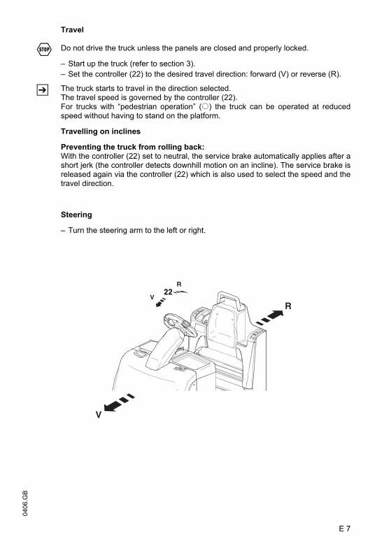
.GBTravel
F Do not drive the truck unless the panels are closed and properly locked.
– Start up the truck (refer to section 3).– Set the controller (22) to the desired travel direction: forward (V) or reverse (R).
Z The truck starts to travel in the direction selected.The travel speed is governed by the controller (22).For trucks with “pedestrian operation” (o) the truck can be operated at reducedspeed without having to stand on the platform.
Travelling on inclines
Preventing the truck from rolling back:With the controller (22) set to neutral, the service brake automatically applies after ashort jerk (the controller detects downhill motion on an incline). The service brake isreleased again via the controller (22) which is also used to select the speed and thetravel direction.
Steering
– Turn the steering arm to the left or right.
R
R
V
V22
E 7
0406
.GB
Travel
F Do not drive the truck unless the panels are closed and properly locked.
– Start up the truck (refer to section 3).– Set the controller (22) to the desired travel direction: forward (V) or reverse (R).
Z The truck starts to travel in the direction selected.The travel speed is governed by the controller (22).For trucks with “pedestrian operation” (o) the truck can be operated at reducedspeed without having to stand on the platform.
Travelling on inclines
Preventing the truck from rolling back:With the controller (22) set to neutral, the service brake automatically applies after ashort jerk (the controller detects downhill motion on an incline). The service brake isreleased again via the controller (22) which is also used to select the speed and thetravel direction.
Steering
– Turn the steering arm to the left or right.
R
R
V
V22

0406
.GB
E 8
Brakes
F The brake pattern of the truck depends largely on the state of the ground. The drivermust take this into account when operating the truck.
M The driver must be looking ahead when travelling. If there is no hazard, brakemoderately to avoid moving the load and to prevent the trailer from veering out.
The truck can be braked in three different ways:
– using the service brake– using the generator brake (coasting)– by plugging (controller)
F In emergencies, the truck must only be braked with the service brake.
Z During normal operation, the generator brake and plugging can be applied. Thesemethods of braking reduce wear and require less energy (energy recovery).
Braking with the service brake:
– Apply the brake button (23).
The truck brakes at the maximum possible deceleration rate until it comes to a halt.
Z The truck can only start again when the controller has been set to “0”.
Braking via the generator brake (coasting):
– Release the controller (25) - the controller assumes the zero position.
Depending on the setting, the truck is braked by the generator brake, coasting to astop.
Z For the standard truck, the rate of deceleration can be adjusted by the manufacturer’sservice department. For trucks with CANCODE and CANDIS it can be adjusted byentering the appropriate setting.
Plugging:
– When travelling, set the controller (25) to the opposite direction.
The truck brakes regeneratively until it starts to move in the opposite direction.
Z The braking intensity depends on theposition of the controller.
23
24
25

E 9
0406
.GB
4.3 Pedestrian operation (o)
F When travelling in pedestrian mode you must make sure – while walking alongside –that the steering system is set to straight ahead travel and that the operator cannotbe trapped between the truck and an obstacle.
Z In pedestrian mode the truck can be operated by the operator from all sides whilewalking alongside. In this case, the truck travels at a significantly reduced speed.
Pedestrian mode is achieved by pressing the “pedestrian” buttons (27, 28) on thebackrest.
Travelling with the “pedestrian” button (o)
– Press the “pedestrian” buttons (27, 28).
The truck travels at a fixed speed of approximately 2km/h (slow travel).
R
R
V
V26
27 28
28R
27V
0406
.GB
E 10
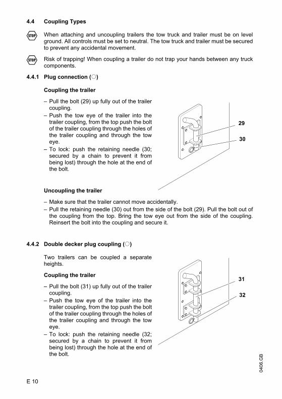
4.4 Coupling Types
F When attaching and uncoupling trailers the tow truck and trailer must be on levelground. All controls must be set to neutral. The tow truck and trailer must be securedto prevent any accidental movement.
F Risk of trapping! When coupling a trailer do not trap your hands between any truckcomponents.
4.4.1 Plug connection (o)
Coupling the trailer
– Pull the bolt (29) up fully out of the trailercoupling.
– Push the tow eye of the trailer into thetrailer coupling, from the top push the boltof the trailer coupling through the holes ofthe trailer coupling and through the toweye.
– To lock: push the retaining needle (30;secured by a chain to prevent it frombeing lost) through the hole at the end ofthe bolt.
Uncoupling the trailer
– Make sure that the trailer cannot move accidentally.– Pull the retaining needle (30) out from the side of the bolt (29). Pull the bolt out of
the coupling from the top. Bring the tow eye out from the side of the coupling.Reinsert the bolt into the coupling and secure it.
4.4.2 Double decker plug coupling (o)
Two trailers can be coupled a separateheights.
Coupling the trailer
– Pull the bolt (31) up fully out of the trailercoupling.
– Push the tow eye of the trailer into thetrailer coupling, from the top push the boltof the trailer coupling through the holes ofthe trailer coupling and through the toweye.
– To lock: push the retaining needle (32;secured by a chain to prevent it frombeing lost) through the hole at the end ofthe bolt.
29
30
31
32
0406
.GB
E 10
4.4 Coupling Types
F When attaching and uncoupling trailers the tow truck and trailer must be on levelground. All controls must be set to neutral. The tow truck and trailer must be securedto prevent any accidental movement.
F Risk of trapping! When coupling a trailer do not trap your hands between any truckcomponents.
4.4.1 Plug connection (o)
Coupling the trailer
– Pull the bolt (29) up fully out of the trailercoupling.
– Push the tow eye of the trailer into thetrailer coupling, from the top push the boltof the trailer coupling through the holes ofthe trailer coupling and through the toweye.
– To lock: push the retaining needle (30;secured by a chain to prevent it frombeing lost) through the hole at the end ofthe bolt.
Uncoupling the trailer
– Make sure that the trailer cannot move accidentally.– Pull the retaining needle (30) out from the side of the bolt (29). Pull the bolt out of
the coupling from the top. Bring the tow eye out from the side of the coupling.Reinsert the bolt into the coupling and secure it.
4.4.2 Double decker plug coupling (o)
Two trailers can be coupled a separateheights.
Coupling the trailer
– Pull the bolt (31) up fully out of the trailercoupling.
– Push the tow eye of the trailer into thetrailer coupling, from the top push the boltof the trailer coupling through the holes ofthe trailer coupling and through the toweye.
– To lock: push the retaining needle (32;secured by a chain to prevent it frombeing lost) through the hole at the end ofthe bolt.
29
30
31
32

E 11
0406
.GBUncoupling the trailer
– Make sure that the trailer cannot move accidentally.– Pull the retaining needle (32) out from the side of the bolt (31). Pull the bolt out of
the coupling from the top. Bring the tow eye out from the side of the coupling.Reinsert the bolt into the coupling and secure it.
4.4.3 Rockinger coupling with hand lever or Bowden cable (o)
The Rockinger coupling comes either withor without remote locking (Bowden cable).
The Rockinger coupling with remote lockingallows trailers to be coupled and uncoupledfrom the platform via a Bowden cable.
Coupling the trailer
– Push the tow eye of the trailer into thetrailer coupling, the bolt of the trailercoupling closes automatically.
Uncoupling the trailer
– Open the tow eye lock by applying the lever (33) or Bowden cable handgrip (34).
4.5 Travelling with trailers
F In difficult application conditions (inclines, smooth or slippery travel routes) the towload must have to be reduced to ensure braking without risk of accidents. The max.permissible load indicated applies only when towing on level surfaces on a goodbearing, non-slip surface.For tow loads in excess of 2000 kg and on inclines, the use of braked trailers isrecommended.
M Always pull, never push a trailer.
Z Familiarise yourself with the brake and steering systems of the trailer when you startto travel.
M On cornering with long trailers and trailer trains, note how the angle is reduced.
1. Start the truck slowly until the trailer coupling has become taut. Then gradually increase the travel speed.
2. To stop, reduce the speed so that both tow truck and trailer gradually slow down. Brake with care!
Z Trailer trains are difficult to shunt. For this reason make sure the angle is correct whencornerning.
3334
E 11
0406
.GB
Uncoupling the trailer
– Make sure that the trailer cannot move accidentally.– Pull the retaining needle (32) out from the side of the bolt (31). Pull the bolt out of
the coupling from the top. Bring the tow eye out from the side of the coupling.Reinsert the bolt into the coupling and secure it.
4.4.3 Rockinger coupling with hand lever or Bowden cable (o)
The Rockinger coupling comes either withor without remote locking (Bowden cable).
The Rockinger coupling with remote lockingallows trailers to be coupled and uncoupledfrom the platform via a Bowden cable.
Coupling the trailer
– Push the tow eye of the trailer into thetrailer coupling, the bolt of the trailercoupling closes automatically.
Uncoupling the trailer
– Open the tow eye lock by applying the lever (33) or Bowden cable handgrip (34).
4.5 Travelling with trailers
F In difficult application conditions (inclines, smooth or slippery travel routes) the towload must have to be reduced to ensure braking without risk of accidents. The max.permissible load indicated applies only when towing on level surfaces on a goodbearing, non-slip surface.For tow loads in excess of 2000 kg and on inclines, the use of braked trailers isrecommended.
M Always pull, never push a trailer.
Z Familiarise yourself with the brake and steering systems of the trailer when you startto travel.
M On cornering with long trailers and trailer trains, note how the angle is reduced.
1. Start the truck slowly until the trailer coupling has become taut. Then gradually increase the travel speed.
2. To stop, reduce the speed so that both tow truck and trailer gradually slow down. Brake with care!
Z Trailer trains are difficult to shunt. For this reason make sure the angle is correct whencornerning.
3334
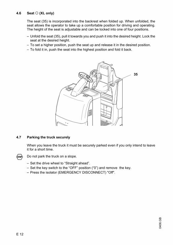
0406
.GB
E 12
4.6 Seat o (XL only)
The seat (35) is incorporated into the backrest when folded up. When unfolded, theseat allows the operator to take up a comfortable position for driving and operating.The height of the seat is adjustable and can be locked into one of four positions.
– Unfold the seat (35), pull it towards you and push it into the desired height. Lock theseat at the desired height.
– To set a higher position, push the seat up and release it in the desired position.– To fold it in, push the seat into the highest position and fold it back.
4.7 Parking the truck securely
When you leave the truck it must be securely parked even if you only intend to leaveit for a short time.
F Do not park the truck on a slope.
– Set the drive wheel to “Straight ahead”.– Set the key switch to the “OFF” position (“0”) and remove the key.– Press the isolator (EMERGENCY DISCONNECT) "Off".
35

E 13
0406
.GB
5 Display instrument (CANDIS) (o)
The instrument indicates:
– Remaining battery charge (LED bars (36)),
– Service hours(LCD display (38)).
It also displays error messages for theelectronic components andparameter changes.
Discharge status display
Setting limits for the additional “Warning” (39) and “Stop” (37)displays will depend onthe battery type.
5.1 Operating hours display
Display range between 0.0 and 99,999.0 hours. Travel movements are collated. Thisis a backlit display.
Z For maintenance-free batteries a “T” symbol is shown in the operating hours display(38).
Error messages
The operating hours display is also used for indicating errors. The error is displayedin two parts, starting with a “C” for component and a three-digit component number,followed by an “E” for error with alternating three-digit error number.If several errors occurs at the same time, they are displayed one after the other. Theerrors are displayed for as long as they remain (always in combination Cxxx / Exxx).Error messages overwrite the service hour display. Most errors cause the EmergencyStop to be triggered. Errors remain displayed until the control circuit is switched off(Code lock).
Z The manufacturer’s service department has detailed component descriptions witherror codes.
Num-ber
of bars
Charge status
Wet battery Maintenance-free batteryLED (yellow)
WarningLED (red)
StopLED (yellow)
WarningLED (red)
Stop10 90.1- 100% Off Off Off Off9 80.1 - 90% Off Off Off Off8 70.1 - 80% Off Off Off Off7 60.1 - 70% Off Off Off Off6 50.1 - 60% Off Off Off Off5 40.1 - 50% Off Off On Off4 30.1 - 40% Off Off On On3 20.1 - 30% On Off On On2 10.1 - 20% On On On On
Avoid falling below the 20% limit for wet batteries or the 40% limitfor maintenance-free batteries.
36
37
38
39
0406
.GB
E 14
Display for parameter changes (travel programs)
The LC display (38) is used in conjunction with the operator keyboard (CANCODE(o)) to display the setting parameters. The first three digits of the display show theparameter numbers, the last three digits indicate the parameter value.
Z Settings of parameter group 0XX (code lock) are not displayed.
5.2 Power up test
On power up the display shows:
– the software version of the display instrument (briefly),– the operating hours– the charge status
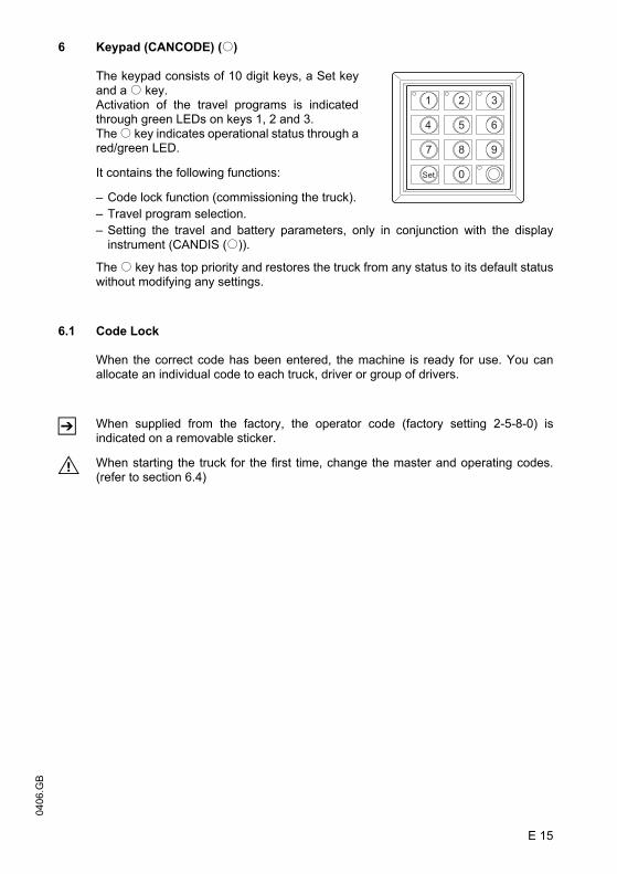
E 15
0406
.GB
6 Keypad (CANCODE) (o)
The keypad consists of 10 digit keys, a Set keyand a o key.Activation of the travel programs is indicatedthrough green LEDs on keys 1, 2 and 3.The o key indicates operational status through ared/green LED.
It contains the following functions:
– Code lock function (commissioning the truck).– Travel program selection.– Setting the travel and battery parameters, only in conjunction with the display
instrument (CANDIS (o)).
The o key has top priority and restores the truck from any status to its default statuswithout modifying any settings.
6.1 Code Lock
When the correct code has been entered, the machine is ready for use. You canallocate an individual code to each truck, driver or group of drivers.
Z When supplied from the factory, the operator code (factory setting 2-5-8-0) isindicated on a removable sticker.
M When starting the truck for the first time, change the master and operating codes.(refer to section 6.4)

0406
.GB
E 16
Starting the truck for the first time
After switching on the isolator and if necessary the key switch, the LED (44) turns red.
When you enter the correct operator code (factory setting 2-5-8-0) the LED (44) turnsgreen.
If the wrong code is entered LED (44) flashes red for two seconds. The correct codecan then be entered.
Z The Set key (45) has no function in operating mode
Power Down
The truck is switched off by pressing the o key (43).
Z The truck can switch off automatically after apre-determined time. To do this thecorresponding code lock parameter must beset (see section 6.4).
40 41 42
43
4445

E 17
0406
.GB
6.2 Travel programs
Press the digit keys 1, 2, and 3 to select any of three travel programs. The activatedprogramme is indicated by the green LEDs (40), (41), (42) in the corresponding key.
Z The travel programmes differ with respect to travelling speed, acceleration, anddeceleration.
Factory settings:
– Program 1: Soft operation– Program 2: Normal operation– Program 3: High performance mode (preset on commissioning)
Z The travel programs can be adapted individually to the truck (refer to section 6.4).
6.3 Parameters
In programming mode, the operator keypad enables you to set the code lockfunctions and adapt travel programs. In addition, the battery parameters can also beset.
Z For trucks without display instrument (CANDIS (o)) only the code lock parameterscan be set.
Parameter Groups
The parameter number is composed of three digits. The first digit refers to theparameter group as shown in Table 1. The second and third digits are numbered insequence from 00 to 99.
No. Parameter Group0xx Code lock settings
((codes, travel program authorisation, automatic cutout, etc.)1xx Travel program 1 parameters
(acceleration, coasting brake, speed, etc.)2xx Travel program 2 parameters
(acceleration, coasting brake, speed, etc.)3xx Travel program 3 parameters
(acceleration, coasting brake, speed, etc.)4xx Program-independent parameters

0406
.GB
E 18
6.4 Parameter Settings
To change the truck setting you must enter the master code.
Z The factory setting for the master code is 7-2-9-5.
M When starting the truck for the first time, change the master code (see Section 6.1).
F Safety notes for trucks with indicator instrument (CANDIS (o))
– Parameter settings must be made carefully and only by special trained personnel .If in doubt, consult the manufacturer's service department.
– Every setting procedure must be monitored on the LC display of the displayinstrument (o)). If in doubt, the setting procedure must be cancelled by pressingthe o key (43)
– Since changing any parameter will affect the truck's travel pattern, you must carryout a test run in a specially designated work area.
To enter the master code:
– Press the o key– Enter master code
Code Lock Parameters
Setting procedure for trucks without display instrument (CANDIS (o)):
– Enter the three digit parameter number and confirm with set key (45).– Enter the setting according to the parameter list or change and confirm with the Set
key (45).
Z If the entry is incorrect, the LED (44) of the o key (43) goes red. If you enter theparameter number again the setting can be entered or changed.
To enter more parameters, repeat the procedure. To complete your entry, press theo key (43).
Display instrument (CANDIS)
LED (44)o key
LED (40)Key 1
LED (41)Key 2
LED (42)Key 3
Service hoursare displayed 284.0 Green
flashingOff Off Off

E 19
0406
.GBSetting procedure for trucks with and without display instrument (CANDIS (o)):
– Enter the three digit parameter number and confirm with set key (45).– The display instrument (CANDIS (o)) continues to display the operating hours. If
the display changes, cancel the setting procedure with the o key (43) and restartfrom the beginning.
– Enter the setting according to the parameter list or change and confirm with the Setkey (45).
Z If the entry is incorrect, the LED (44) of the o key (43) goes red. If you enter theparameter number again the setting can be entered or changed.
To enter more parameters, repeat the procedure. To complete your entry, press theo key (43).
The following parameters may be entered.
Code Lock Parameter List
No. Function Settingrange
Standard setting
CommentsProcedure
Code Lock000 Change master code
The length (4-6 digits) of the master code also pre-determines the length of the operator code (4-6 digits). Provided the operator codes are programmed, only news codes of the same length can be entered. If the code length is to be changed, all operator codes must first be deleted.
0000 - 9999or
00000 - 99999or
000000 - 999999
7295 (LED 40 flashes)Enter
current code
Confirm (Set)
(LED 41 flashes)Enter a
new code
Confirm (Set)
(LED 42 flashes)Repeat new code
Confirm (Set)001 Add operator code (max.
600)0000 - 9999
or00000 - 99999
or000000 - 999999
2580 (LED 41 flashes)Enter acode
Confirm (Set)
(LED 42 flashes)Repeat code
entry
Confirm (Set)
E 19
0406
.GB
Setting procedure for trucks with and without display instrument (CANDIS (o)):
– Enter the three digit parameter number and confirm with set key (45).– The display instrument (CANDIS (o)) continues to display the operating hours. If
the display changes, cancel the setting procedure with the o key (43) and restartfrom the beginning.
– Enter the setting according to the parameter list or change and confirm with the Setkey (45).
Z If the entry is incorrect, the LED (44) of the o key (43) goes red. If you enter theparameter number again the setting can be entered or changed.
To enter more parameters, repeat the procedure. To complete your entry, press theo key (43).
The following parameters may be entered.
Code Lock Parameter List
No. Function Settingrange
Standard setting
CommentsProcedure
Code Lock000 Change master code
The length (4-6 digits) of the master code also pre-determines the length of the operator code (4-6 digits). Provided the operator codes are programmed, only news codes of the same length can be entered. If the code length is to be changed, all operator codes must first be deleted.
0000 - 9999or
00000 - 99999or
000000 - 999999
7295 (LED 40 flashes)Enter
current code
Confirm (Set)
(LED 41 flashes)Enter a
new code
Confirm (Set)
(LED 42 flashes)Repeat new code
Confirm (Set)001 Add operator code (max.
600)0000 - 9999
or00000 - 99999
or000000 - 999999
2580 (LED 41 flashes)Enter acode
Confirm (Set)
(LED 42 flashes)Repeat code
entry
Confirm (Set)
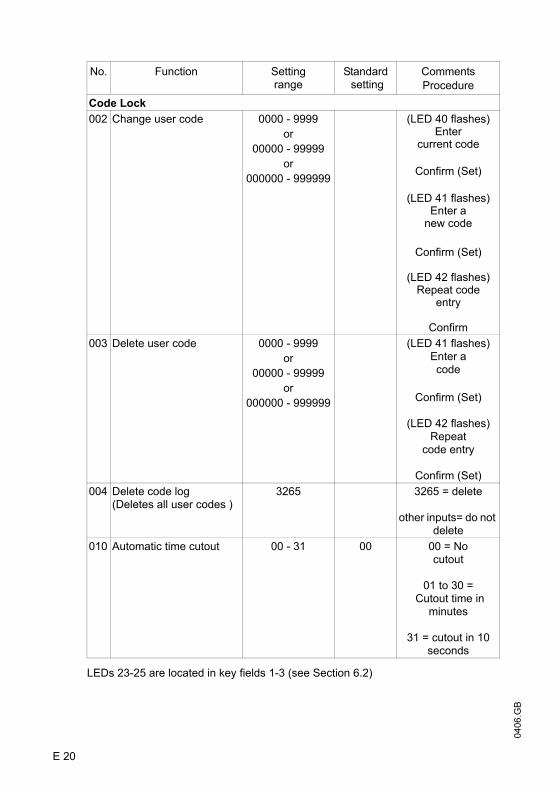
0406
.GB
E 20
LEDs 23-25 are located in key fields 1-3 (see Section 6.2)
No. Function Settingrange
Standard setting
CommentsProcedure
Code Lock002 Change user code 0000 - 9999
or00000 - 99999
or000000 - 999999
(LED 40 flashes)Enter
current code
Confirm (Set)
(LED 41 flashes)Enter a
new code
Confirm (Set)
(LED 42 flashes)Repeat code
entry
Confirm003 Delete user code 0000 - 9999
or00000 - 99999
or000000 - 999999
(LED 41 flashes)Enter acode
Confirm (Set)
(LED 42 flashes)Repeat
code entry
Confirm (Set)004 Delete code log
(Deletes all user codes )3265 3265 = delete
other inputs= do not delete
010 Automatic time cutout 00 - 31 00 00 = No cutout
01 to 30 = Cutout time in
minutes
31 = cutout in 10 seconds
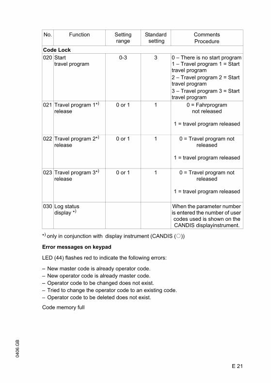
E 21
0406
.GB
*) only in conjunction with display instrument (CANDIS (o))
Error messages on keypad
LED (44) flashes red to indicate the following errors:
– New master code is already operator code.– New operator code is already master code.– Operator code to be changed does not exist.– Tried to change the operator code to an existing code.– Operator code to be deleted does not exist.
Code memory full
No. Function Settingrange
Standard setting
CommentsProcedure
Code Lock020 Start
travel program0-3 3 0 – There is no start program
1 – Travel program 1 = Start travel program2 – Travel program 2 = Start travel program3 – Travel program 3 = Start travel program
021 Travel program 1*)
release0 or 1 1 0 = Fahrprogram
not released
1 = travel program released
022 Travel program 2*)
release0 or 1 1 0 = Travel program not
released
1 = travel program released
023 Travel program 3*)
release0 or 1 1 0 = Travel program not
released
1 = travel program released
030 Log status display *)
When the parameter number is entered the number of user codes used is shown on the CANDIS displayinstrument.
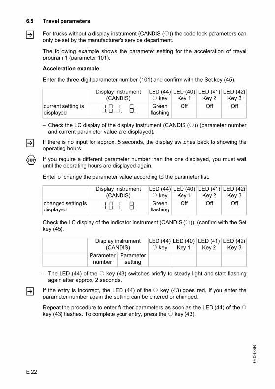
0406
.GB
E 22
6.5 Travel parameters
Z For trucks without a display instrument (CANDIS (o)) the code lock parameters canonly be set by the manufacturer's service department.
The following example shows the parameter setting for the acceleration of travelprogram 1 (parameter 101).
Acceleration example
Enter the three-digit parameter number (101) and confirm with the Set key (45).
– Check the LC display of the display instrument (CANDIS (o)) (parameter numberand current parameter value are displayed).
Z If there is no input for approx. 5 seconds, the display switches back to showing theoperating hours.
F If you require a different parameter number than the one displayed, you must waituntil the operating hours are displayed again.
Enter or change the parameter value according to the parameter list.
Check the LC display of the indicator instrument (CANDIS (o)), (confirm with the Setkey (45).
– The LED (44) of the o key (43) switches briefly to steady light and start flashingagain after approx. 2 seconds.
Z If the entry is incorrect, the LED (44) of the o key (43) goes red. If you enter theparameter number again the setting can be entered or changed.
Repeat the procedure to enter further parameters as soon as the LED (44) of the okey (43) flashes. To complete your entry, press the o key (43).
Display instrument (CANDIS)
LED (44)o key
LED (40)Key 1
LED (41)Key 2
LED (42)Key 3
current setting is displayed 101 6
Greenflashing
Off Off Off
Display instrument (CANDIS)
LED (44)o key
LED (40)Key 1
LED (41)Key 2
LED (42)Key 3
changed setting is displayed 101 8
Greenflashing
Off Off Off
Display instrument (CANDIS)
LED (44)o key
LED (40)Key 1
LED (41)Key 2
LED (42)Key 3
Parameter number
Parameter setting

E 23
0406
.GB
Z Travel is disabled while the parameters are being entered. If the setting is to bechecked in programming mode, follow this sequence:
– Select the edited travel program after changing the parameter value, confirm withthe Set key (45).
– The truck is now in travel mode and can be checked.– To continue setting, confirm with the Set key (45) again.
The following parameters may be entered.
Travel programs
No. Function Settingrange
Standard setting
Comments
Travel program 1100 Acceleration in
Pedestrian mode0 - 9 2 Value of parameter
101 >= Parameter 100
101 Acceleration inRider mode
0 - 9 2
102 Coasting brake in rider mode
0 - 9 2
103 Coasting brake inPedestrian mode
0 - 9 2 Value of parameter 103 >= Parameter 102
104 Maximum speed in drive direction via controller
0 - 9 8 depending ontravel switch
105 Pedestrian speed in drive direction via controller
0 - 9 5 depending ontravel switch
106 Pedestrian speed in drive direction via pushbutton in backrest
0 - 9 3 not dependant on travel switch(fixed speed)
108 Maximum speed in fork direction via controller
0 - 9 8 depending ontravel switch
109 Pedestrian speed in fork direction via controller
0 - 9 5 depending ontravel switch
110 Pedestrian speed in fork direction via pushbutton in backrest
0 - 9 3 not dependant on travel switch(fixed speed)

0406
.GB
E 24
No. Function Settingrange
Standard setting
Comments
Travel program 2200 Acceleration in
Pedestrian mode0 - 9 5 Value of parameter
201 >= Parameter 200
201 Acceleration inRider mode
0 - 9 5
202 Coasting brake in rider mode
0 - 9 5
203 Coasting brake inPedestrian mode
0 - 9 5 Value of parameter 203 >= Parameter 202
204 Maximum speed in drive direction via controller
0 - 9 8 depending ontravel switch
205 Pedestrian speed in drive direction via controller
0 - 9 5 depending ontravel switch
206 Pedestrian speed in drive direction via pushbutton in backrest
0 - 9 3 not dependant on travel switch(fixed speed)
208 Maximum speed in fork direction via controller
0 - 9 8 depending ontravel switch
209 Pedestrian speed in fork direction via controller
0 - 9 5 depending ontravel switch
210 Pedestrian speed in fork direction via pushbutton in backrest
0 - 9 3 not dependant on travel switch(fixed speed)

E 25
0406
.GB
No. Function Settingrange
Standard setting
Comments
Travel program 3300 Acceleration in
Pedestrian mode0 - 9 7 Value of parameter
301 >= Parameter 300
301 Acceleration inRider mode
0 - 9 7
302 Coasting brake in rider mode
0 - 9 7
303 Coasting brake inPedestrian mode
0 - 9 7 Value of parameter 303 >= Parameter 302
304 Maximum speed in drive direction via controller
0 - 9 8 depending ontravel switch
305 Pedestrian speed in drive direction via controller
0 - 9 5 depending ontravel switch
306 Pedestrian speed in drive direction via pushbutton in backrest
0 - 9 3 not dependant on travel switch(fixed speed)
308 Maximum speed in fork direction via controller
0 - 9 8 depending ontravel switch
309 Pedestrian speed in fork direction via controller
0 - 9 5 depending ontravel switch
310 Pedestrian speed in fork direction via pushbutton in backrest
0 - 9 3 not dependant on travel switch(fixed speed)
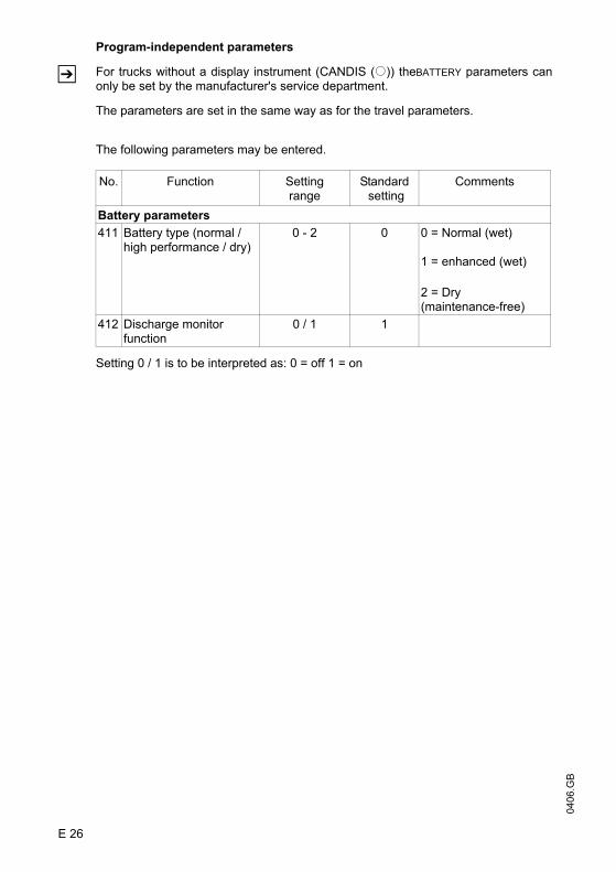
0406
.GB
E 26
Program-independent parameters
Z For trucks without a display instrument (CANDIS (o)) theBATTERY parameters canonly be set by the manufacturer's service department.
The parameters are set in the same way as for the travel parameters.
The following parameters may be entered.
Setting 0 / 1 is to be interpreted as: 0 = off 1 = on
No. Function Settingrange
Standard setting
Comments
Battery parameters411 Battery type (normal /
high performance / dry)0 - 2 0 0 = Normal (wet)
1 = enhanced (wet)
2 = Dry(maintenance-free)
412 Discharge monitor function
0 / 1 1
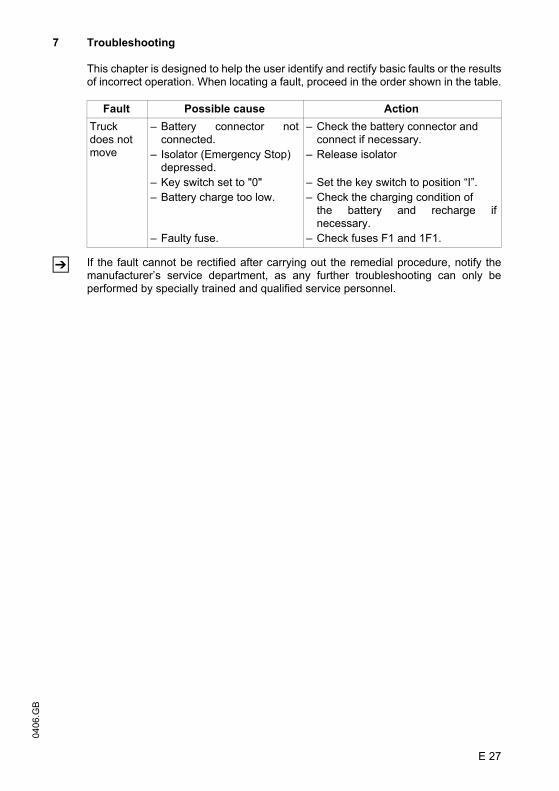
E 27
0406
.GB
7 Troubleshooting
This chapter is designed to help the user identify and rectify basic faults or the resultsof incorrect operation. When locating a fault, proceed in the order shown in the table.
Z If the fault cannot be rectified after carrying out the remedial procedure, notify themanufacturer’s service department, as any further troubleshooting can only beperformed by specially trained and qualified service personnel.
Fault Possible cause ActionTruck does not move
– Battery connector notconnected.
– Isolator (Emergency Stop) depressed.
– Key switch set to "0"– Battery charge too low.
– Faulty fuse.
– Check the battery connector and connect if necessary.
– Release isolator
– Set the key switch to position “I”.– Check the charging condition of
the battery and recharge ifnecessary.
– Check fuses F1 and 1F1.

0406
.GB
E 28
0406
.GB
E 28

F 1
0406
.GB
F Industrial Truck Maintenance1 Operational safety and environmental protection
The servicing and inspection duties contained in this chapter must be performed inaccordance with the intervals indicated in the maintenance checklists.
F Any modification to the forklift truck assemblies, in particular the safety mechanisms,is prohibited. The operational speeds of the truck must not be changed under anycircumstances.
M Only original spare parts have been certified by our quality assurance department. Toensure safe and reliable operation of the forklift truck, use only the manufacturer'sspare parts. Used parts, oils and fuels must be disposed of in accordance with therelevant environmental protection regulations. For oil changes, contact themanufacturer’s specialist department.
Upon completion of inspection and servicing, the tasks contained in the“Recommissioning” section must be performed (see chapter F).
2 Maintenance Safety Regulations
Maintenance personnel: Industrial trucks must only be serviced and maintained bythe manufacturer’s trained personnel. The manufacturer’s service department hasfield technicians specially trained for these tasks. We therefore recommend amaintenance contract with the manufacturer’s local service centre.
Lifting and jacking up: When an industrial truck is to be lifted, the lifting gear mustonly be secured to the points specially provided for this purpose. When jacking up thetruck, take appropriate measures to prevent the truck from slipping or tipping over(e.g. wedges, wooden blocks).
Cleaning: Do not use flammable liquids to clean the industrial truck. Prior to cleaning,implement all necessary safety measures to prevent sparking (e.g. through shortcircuits). For battery-operated trucks, the battery connector must be removed. Onlyweak suction or compressed air and non-conductive antistatic brushes may be usedfor cleaning electric or electronic assemblies.
M If the truck is to be cleaned with a water jet or a high-pressure cleaner, all electricaland electronic components must be carefully covered beforehand as moisture cancause malfunctions..Do not clean with pressurised water.
After cleaning the truck, carry out the activities detailed in the “Recommissioning”section.

0406
.GB
F 2
Electrical System: Only suitably trained personnel may operate on the truck’selectrical system. Before working on the electrical system, take all precautionarymeasures to avoid electric shocks. For battery-operated trucks, also de-energise thetruck by removing the battery connector.
Welding: To avoid damaging electric or electronic components, remove these fromthe truck before performing welding operations.
Settings: When repairing or replacing hydraulic, electric or electronic components orassemblies, always note the truck-specific settings.
Tyres: The quality of tyres affects the stability and performance of the truck. Whenreplacing tyres fitted at the factory, only use the manufacturer’s original spare parts.Otherwise the data sheet specifications of the truck cannot be guaranteed. Whenchanging wheels and tyres, ensure that the truck does not slew (e.g. when replacingwheels always left and right simultaneously).

F 3
0406
.GB
3 Servicing and inspection
Thorough and expert servicing is one of the most important requirements for the safeoperation of the industrial truck. Failure to perform regular servicing can lead to truckfailure and poses a potential hazard to personnel and equipment.
M The service intervals stated are based on single shift operation under normaloperating conditions. They must be reduced accordingly if the truck is to be used inconditions of extreme dust, temperature fluctuations or multiple shifts.
The following maintenance checklist states the tasks and intervals after which theyshould be carried out. Maintenance intervals are defined as:
W = Every 50 service hours, at least weeklyA = Every 500 service hoursB = Every 1000 service hours, or at least annually.C = Every 2000 service hours, or at least annually
Z W service intervals are to be performed by the customer.
During the run-in period – after approx. 100 service hours – the owner must checkthe wheel nuts/bolts and re-tighten if necessary.
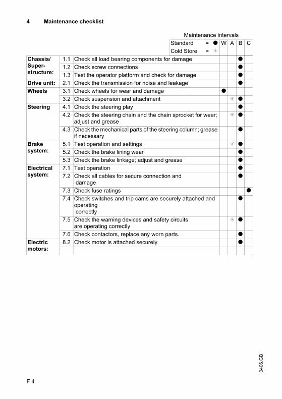
0406
.GB
F 4
4 Maintenance checklist
Maintenance intervalsStandard = t W A B CCold Store = k
Chassis/Super-structure:
1.1 Check all load bearing components for damage t1.2 Check screw connections t1.3 Test the operator platform and check for damage t
Drive unit: 2.1 Check the transmission for noise and leakage tWheels 3.1 Check wheels for wear and damage t
3.2 Check suspension and attachment l tSteering 4.1 Check the steering play t
4.2 Check the steering chain and the chain sprocket for wear; adjust and grease
l t
4.3 Check the mechanical parts of the steering column; grease if necessary
t
Brake system:
5.1 Test operation and settings l t5.2 Check the brake lining wear t5.3 Check the brake linkage; adjust and grease t
Electrical system:
7.1 Test operation t7.2 Check all cables for secure connection and
damaget
7.3 Check fuse ratings t7.4 Check switches and trip cams are securely attached and
operating correctly
t
7.5 Check the warning devices and safety circuits are operating correctly
l t
7.6 Check contactors, replace any worn parts. tElectric motors:
8.2 Check motor is attached securely t
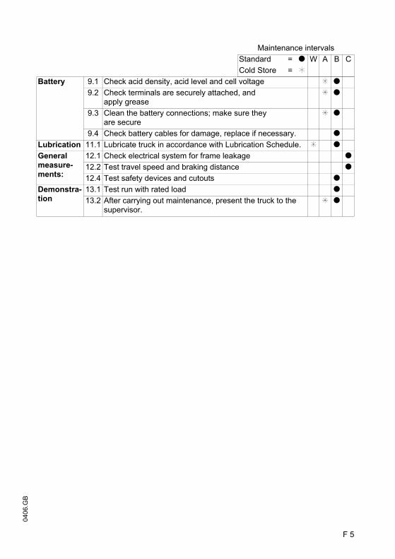
F 5
0406
.GB
Maintenance intervalsStandard = t W A B CCold Store = k
Battery 9.1 Check acid density, acid level and cell voltage l t9.2 Check terminals are securely attached, and
apply greasel t
9.3 Clean the battery connections; make sure they are secure
l t
9.4 Check battery cables for damage, replace if necessary. tLubrication 11.1 Lubricate truck in accordance with Lubrication Schedule. l tGeneral measure-ments:
12.1 Check electrical system for frame leakage t12.2 Test travel speed and braking distance t12.4 Test safety devices and cutouts t
Demonstra-tion
13.1 Test run with rated load t13.2 After carrying out maintenance, present the truck to the
supervisor.l t

0406
.GB
F 6
5 Lubrication Schedule
g Contact surfacess Grease nippleb Transmission oil filler necka Transmission oil drain plug
Cold store application
1) Compound ratio for cold store usage 1:1
G
B b
a
E
B+C 1) 1.4l
0406
.GB
F 6
5 Lubrication Schedule
g Contact surfacess Grease nippleb Transmission oil filler necka Transmission oil drain plug
Cold store application
1) Compound ratio for cold store usage 1:1
G
B b
a
E
B+C 1) 1.4l

F 7
0406
.GB
5.1 Consumables
Handling consumption type material: Consumables must always be handledcorrectly. Follow the manufacturer’s instructions.
F Improper handling is hazardous to health, life and the environment. Consumablesmust only be stored in appropriate containers. They may be flammable and musttherefore not come into contact with hot components or naked flames.
Only use clean containers when filling up with consumables. Do not mix consumablesof different grades. The only exception to this is if mixing is expressively prescribedin the corresponding operating instructions.
Avoid spillage. Spilled liquids must be removed immediately with suitable bondingagents and the bonding agent / consumable mixture must be disposed of inaccordance with regulations.
Grease guidelines
Code Order no. Quantity Description Used forB 50 380 904 5,0 l Fuchs Titan Gear
HSY 75W-90Transmission
C 29 200 810 5.0 l H-LP 10, DIN 51524 TransmissionE 29 201 430 1.0 kg Grease, DIN 51825 LubricationF 29 200 100 1.0 kg Grease, TTF52 LubricationG 29 201 280 0.4 l Chain spray Chains
Code Saponifica-tion
Dew point °C
Worked penetration at
25 °C
NLG1 class
Application temperature °C
E Lithium 185 265 - 295 2 -35 / +120F — — 310 - 340 1 -52 / +100
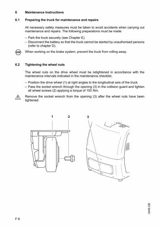
0406
.GB
F 8
6 Maintenance Instructions
6.1 Preparing the truck for maintenance and repairs
All necessary safety measures must be taken to avoid accidents when carrying outmaintenance and repairs. The following preparations must be made:
– Park the truck securely (see Chapter E).– Disconnect the battery so that the truck cannot be started by unauthorised persons
(refer to chapter D).
F When working on the brake system, prevent the truck from rolling away.
6.2 Tightening the wheel nuts
The wheel nuts on the drive wheel must be retightened in accordance with themaintenance intervals indicated in the maintenance checklist.
– Position the drive wheel (1) at right angles to the longitudinal axis of the truck.– Pass the socket wrench through the opening (3) in the collision guard and tighten
all wheel screws (2) applying a torque of 150 Nm.
M Remove the socket wrench from the opening (3) after the wheel nuts have beentightened.
1 2 3
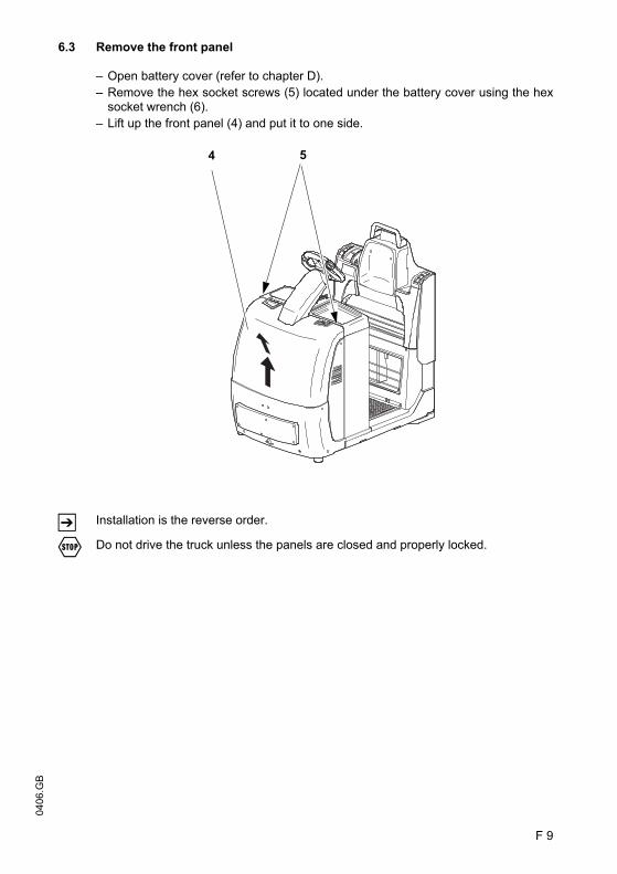
F 9
0406
.GB
6.3 Remove the front panel
– Open battery cover (refer to chapter D).– Remove the hex socket screws (5) located under the battery cover using the hex
socket wrench (6).– Lift up the front panel (4) and put it to one side.
Z Installation is the reverse order.
F Do not drive the truck unless the panels are closed and properly locked.
4 5

0406
.GB
F 10
6.4 Checking electrical fuses
– Prepare the truck for maintenance and repairs (see Chapter 6.1).
– Remove the front panel (see Section 6.3).– Referring to the table, check all fuses for correct rating and damage; replace fuses
where required.
– Reinstall the front panel (see section 6.3).
Item Description To protect: Rating6 6F1 Battery discharge indicator / battery hourmeter 2 A7 F1 Overall control circuit fuse 10 A8 3F6 Steer motor / steering 30 A9 1F1 Drive motor 300 A
67
8
9

F 11
0406
.GB
6.5 Recommissioning
The truck may only be restored to service after cleaning or repair work, once thefollowing operations have been performed.
– Test horn.– Test main switch operation.– Test brakes.– Lubricate the truck in accordance with the lubrication schedule.
7 Decommissioning the industrial truck
If the industrial truck is to be decommissioned for more than two months, e.g. foroperational reasons, it must be parked in a frost-free and dry location and allnecessary measures must be taken before, during and after decommissioning asdescribed.
M On decommissioning the truck must be jacked up so that all the wheels are clear ofthe ground. This is the only way of ensuring that the wheels and wheel bearings arenot damaged.
If the truck is to be out of service for more than 6 months, further measures must betaken in consultation with the manufacturer’s service department.
7.1 Prior to decommissioning:
– Thoroughly clean the truck.– Check the brakes.– Apply a thin layer of oil or grease to any non-painted mechanical components.– Lubricate the truck in accordance with the lubrication schedule (see Chapter F).– Charge the battery (see Chapter D).– Disconnect the battery, clean it and grease the terminals.
Z In addition, follow the battery manufacturer’s instructions.
– Spay all exposed electrical contacts with a suitable contact spray.
7.2 During decommissioning:
Every 2 months:
– Charge the battery (see Chapter D).
M Battery powered trucks:The battery must be charged at regular intervals to avoid depletion of the batterythrough self-discharge. The sulfatisation would destroy the battery.

0406
.GB
F 12
7.3 Returning the truck to operation after decommissioning
– Thoroughly clean the truck.– Lubricate the truck in accordance with the lubrication schedule (see Chapter F).– Clean the battery, grease the terminals and connect the battery.– Charge the battery (see Chapter D).– Check transmission oil for condensed water and replace if necessary.– Start up the truck (see Chapter E).
Z Battery powered trucks:If there are switching problems in the electrical system, apply contact spray to theexposed contacts and remove any oxide layers on the contacts of the operatingcontrols by applying them repeatedly.
F Perform several brake tests immediately after re-commissioning the truck.
8 Safety checks to be performed at regular intervals and following any unusualincidents (D: Accident prevention check according to BGV D27
The truck must be inspected at least annually or after any unusual event by a qualifiedinspector. The inspector shall assess the condition of the truck from purely a safetyviewpoint, without regard to operational or economic circumstances. The inspectorshall be sufficiently instructed and experienced to be able to assess the condition ofthe truck and the effectiveness of the safety mechanisms based on the technicalregulations and principles governing the inspection of forklift trucks.
A thorough test of the truck must be undertaken with regard to its technical conditionfrom a safety aspect. The truck must also be examined for damage caused bypossible improper use. A test report shall be provided. The test results must be keptfor at least the next 2 inspections.
The owner is responsible for ensuring that faults are immediately rectified.
Z The manufacturer has a safety department with trained personnel to carry outinspections. A test plate is attached to the truck as proof that it has passed the safetyinspection. This plate indicates the due date for the next inspection.
9 Final de-commissioning, disposal
Z Final, correct de-commissioning or disposal of the truck must be performed inaccordance with the regulations of the country of use. In particular, regulationsgoverning the disposal of batteries, fuels and electronic and electrical systems mustbe observed..

1
0506
.GB
Instructions for use
Jungheinrich traction battery
Table of contents1 Jungheinrich traction battery
with positive tubular plates type EPzS and EPzB..........................................2-6
Type plate Jungheinrich traction battery............................................7
Instruction for useAquamatic/BFS III water refilling system ......................................................8-12
2 Jungheinrich traction batteryMaintenance free traction batteries with positive tubular plates type EPzV and EPzV-BS ............................................................................................13-17
Type plate Jungheinrich traction battery............................................17
0506
.GB
2
1 Jungheinrich traction battery
with positive tubular plates type EPzS and EPzB
Rating Data
1. Nominal capacity C5: See type plate2. Nominal voltage: 2,0 V x No of cells3. Discharge current:: C5/5h4. Nominal S.G. of electrolyte*
Type EPzS: 1,29 kg/lType EPzB: 1,29 kg/l
5. Rated temperature: 30° C6. Nominal electrolyte level: up to electrolyte level mark „max.“
* Will be reached within the first 10 cycles.
•Pay attention to the operation instruction and fix them close to the battery!•Work on batteries to be carried out by skilled personnel only!
•Use protective glasses and clothes when working on batteries!•Pay attention to the accident prevention rules as well as DIN EN 50272-3, DIN 50110-1!
•No smoking!•Do not expose batteries to naked flames, glowing embers or sparks, as it may cause the battery to explode!
•Acid splashes in the eyes or on the skin must be washed with water. In case of accident consult a doctor immediately!•Clothing contaminated by acid should be washed in water.
•Risk of explosion and fire, avoid short circuits!
•Electrolyte is highly corrosive!
•Batteries and cells are heavy!•Ensure secure installation! Use only suitable handling equipment e.g. lifting gear in accordance with VDI 3616.
•Dangerous electrical voltage!•Caution! Metal parts of the battery are always live. Do not place tools or other me-tal objects on the battery!
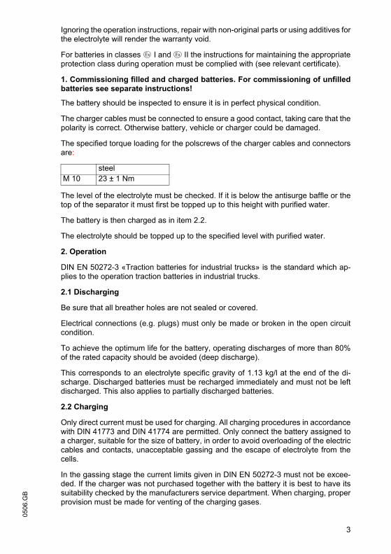
3
0506
.GBIgnoring the operation instructions, repair with non-original parts or using additives forthe electrolyte will render the warranty void.
For batteries in classes I and II the instructions for maintaining the appropriateprotection class during operation must be complied with (see relevant certificate).
1. Commissioning filled and charged batteries. For commissioning of unfilledbatteries see separate instructions!
The battery should be inspected to ensure it is in perfect physical condition.
The charger cables must be connected to ensure a good contact, taking care that thepolarity is correct. Otherwise battery, vehicle or charger could be damaged.
The specified torque loading for the polscrews of the charger cables and connectorsare:
The level of the electrolyte must be checked. If it is below the antisurge baffle or thetop of the separator it must first be topped up to this height with purified water.
The battery is then charged as in item 2.2.
The electrolyte should be topped up to the specified level with purified water.
2. Operation
DIN EN 50272-3 «Traction batteries for industrial trucks» is the standard which ap-plies to the operation traction batteries in industrial trucks.
2.1 Discharging
Be sure that all breather holes are not sealed or covered.
Electrical connections (e.g. plugs) must only be made or broken in the open circuitcondition.
To achieve the optimum life for the battery, operating discharges of more than 80%of the rated capacity should be avoided (deep discharge).
This corresponds to an electrolyte specific gravity of 1.13 kg/l at the end of the di-scharge. Discharged batteries must be recharged immediately and must not be leftdischarged. This also applies to partially discharged batteries.
2.2 Charging
Only direct current must be used for charging. All charging procedures in accordancewith DIN 41773 and DIN 41774 are permitted. Only connect the battery assigned toa charger, suitable for the size of battery, in order to avoid overloading of the electriccables and contacts, unacceptable gassing and the escape of electrolyte from thecells.
In the gassing stage the current limits given in DIN EN 50272-3 must not be excee-ded. If the charger was not purchased together with the battery it is best to have itssuitability checked by the manufacturers service department. When charging, properprovision must be made for venting of the charging gases.
steel M 10 23 ± 1 Nm
3
0506
.GB
Ignoring the operation instructions, repair with non-original parts or using additives forthe electrolyte will render the warranty void.
For batteries in classes I and II the instructions for maintaining the appropriateprotection class during operation must be complied with (see relevant certificate).
1. Commissioning filled and charged batteries. For commissioning of unfilledbatteries see separate instructions!
The battery should be inspected to ensure it is in perfect physical condition.
The charger cables must be connected to ensure a good contact, taking care that thepolarity is correct. Otherwise battery, vehicle or charger could be damaged.
The specified torque loading for the polscrews of the charger cables and connectorsare:
The level of the electrolyte must be checked. If it is below the antisurge baffle or thetop of the separator it must first be topped up to this height with purified water.
The battery is then charged as in item 2.2.
The electrolyte should be topped up to the specified level with purified water.
2. Operation
DIN EN 50272-3 «Traction batteries for industrial trucks» is the standard which ap-plies to the operation traction batteries in industrial trucks.
2.1 Discharging
Be sure that all breather holes are not sealed or covered.
Electrical connections (e.g. plugs) must only be made or broken in the open circuitcondition.
To achieve the optimum life for the battery, operating discharges of more than 80%of the rated capacity should be avoided (deep discharge).
This corresponds to an electrolyte specific gravity of 1.13 kg/l at the end of the di-scharge. Discharged batteries must be recharged immediately and must not be leftdischarged. This also applies to partially discharged batteries.
2.2 Charging
Only direct current must be used for charging. All charging procedures in accordancewith DIN 41773 and DIN 41774 are permitted. Only connect the battery assigned toa charger, suitable for the size of battery, in order to avoid overloading of the electriccables and contacts, unacceptable gassing and the escape of electrolyte from thecells.
In the gassing stage the current limits given in DIN EN 50272-3 must not be excee-ded. If the charger was not purchased together with the battery it is best to have itssuitability checked by the manufacturers service department. When charging, properprovision must be made for venting of the charging gases.
steel M 10 23 ± 1 Nm

0506
.GB
4
Battery container lids and the covers of battery compartments must be opened or re-moved. The vent plugs should stay on the cells and remain closed.
With the charger switched off connect up the battery, ensuring that the polarity is cor-rect. (positive to positive, negative to negative). Now switch on the charger. Whencharging the temperature of the electrolyte rises by about 10°C, so charging shouldonly begin if the electrolyte temperature is below 45°C. The electrolyte temperatureof batteries should be at least +10°C before charging otherwise a full charge will notbe achieved.
A charge is finished when the specific gravity of the electrolyte and the battery voltagehave remained constant for two hours. Special instructions for the operation of batte-ries in hazardous areas. This concerns batteries which are used in accordance withEN 50014, DIN VDE 0170/0171 Ex (in areas with a firedamp hazard) or Ex II (in po-tentially explosive areas). During charging and subsequent gassing the container lidsmust be removed or opened so that the explosive mixture of gases loses its flamma-bility due to adequate ventilation. The containers for batteries with plate protectionpacks must not be closed until at least half an hour after charging has past.
2.3 Equalising charge
Equalising charges are used to safeguard the life of the battery and to maintain itscapacity. They are necessary after deep discharges, repeated incomplete rechargesand charges to an IU characteristic curve. Equalising charges are carried out follo-wing normal charging. The charging current must not exceed 5 A/100 Ah of rated ca-pacity (end of charge - see point 2.2).
Watch the temperature!
2.4 Temperature
An electrolyte temperature of 30°C is specified as the rated temperature. Higher tem-peratures shorten the life of the battery, lower temperatures reduce the capacity avai-lable. 55°C is the upper temperature limit and is not acceptable as an operating tem-perature.
2.5 Electrolyte
The rated specific gravity (S. G.) of the electrolyte is related to a temperature of 30°Cand the nominal electrolyte level in the cell in fully charged condition. Higher tempe-ratures reduce the specified gravity of the electrolyte, lower temperatures increase it.The temperature correction factor is -0.0007 kg/l per °C, e.g. an electrolyte specificgravity of 1.28 kg/l at 45°C corresponds to an S.G. of 1.29 kg/l at 30°C.
The electrolyte must conform to the purity regulations in DIN 43530 part 2.

5
0506
.GB3. Maintenance
3.1 Daily
Charge the battery after every discharge. Towards the end of charge the electrolytelevel should be checked and if necessary topped up to the specified level with purifiedwater. The electrolyte level must not fall below the anti-surge baffle or the top of theseparator or the electrolyte „min“ level mark.
3.2 Weekly
Visual inspection after recharging for signs of dirt and mechanical damage. If the bat-tery is charged regularly with a IU characteristic curve an equalising charge must becarried out (see point 2.3).
3.3 Monthly
At the end of the charge the voltages of all cells or bloc batteries should be measuredwith the charger switched on, and recorded. After charging has ended the specificgravity and the temperature of the electrolyte in all cells should be measured and re-corded.
If significant changes from earlier measurements or differences between the cells orbloc batteries are found further testing and maintenance by the service departmentshould be requested.
3.4 Annually
In accordance with DIN VDE 0117 at least once per year, the insulation resistance ofthe truck and the battery must be checked by an electrical specialist.
The tests on the insulation resistance of the battery must be conducted in accordancewith DIN EN 60254-1.
The insulation resistance of the battery thus determined must not be below a value of50 Ω per Volt of nominal voltage, in compliance with DIN EN 50272-3.
For batteries up to 20 V nominal voltage the minimum value is 1000 Ω.
4. Care of the battery
The battery should always be kept clean and dry to prevent tracking currents. Clea-ning must be done in accordance with the ZVEI code of practice «The Cleaning ofVehicle Traction batteries».
Any liquid in the battery tray must be extracted and disposed of in the prescribed man-ner. Damage to the insulation of the tray should be repaired after cleaning, to ensurethat the insulation value complies DIN EN 50272-3 and to prevent tray corrosion. If itis necessary to remove cells it is best to call in our service department for this.
5
0506
.GB
3. Maintenance
3.1 Daily
Charge the battery after every discharge. Towards the end of charge the electrolytelevel should be checked and if necessary topped up to the specified level with purifiedwater. The electrolyte level must not fall below the anti-surge baffle or the top of theseparator or the electrolyte „min“ level mark.
3.2 Weekly
Visual inspection after recharging for signs of dirt and mechanical damage. If the bat-tery is charged regularly with a IU characteristic curve an equalising charge must becarried out (see point 2.3).
3.3 Monthly
At the end of the charge the voltages of all cells or bloc batteries should be measuredwith the charger switched on, and recorded. After charging has ended the specificgravity and the temperature of the electrolyte in all cells should be measured and re-corded.
If significant changes from earlier measurements or differences between the cells orbloc batteries are found further testing and maintenance by the service departmentshould be requested.
3.4 Annually
In accordance with DIN VDE 0117 at least once per year, the insulation resistance ofthe truck and the battery must be checked by an electrical specialist.
The tests on the insulation resistance of the battery must be conducted in accordancewith DIN EN 60254-1.
The insulation resistance of the battery thus determined must not be below a value of50 Ω per Volt of nominal voltage, in compliance with DIN EN 50272-3.
For batteries up to 20 V nominal voltage the minimum value is 1000 Ω.
4. Care of the battery
The battery should always be kept clean and dry to prevent tracking currents. Clea-ning must be done in accordance with the ZVEI code of practice «The Cleaning ofVehicle Traction batteries».
Any liquid in the battery tray must be extracted and disposed of in the prescribed man-ner. Damage to the insulation of the tray should be repaired after cleaning, to ensurethat the insulation value complies DIN EN 50272-3 and to prevent tray corrosion. If itis necessary to remove cells it is best to call in our service department for this.

0506
.GB
6
5. Storage
If batteries are taken out of service for a lengthy period they should be stored in thefully charged condition in a dry, frost-free room. To ensure the battery is always readyfor use a choice of charging methods can be made:
1. a monthly equalising charge as in point 2.3
2. float charging at a charging voltage of 2.23 V x the number of cells. The storagetime should be taken into account when considering the life of the battery.
6. Malfunctions
If malfunctions are found on the battery or the charger our service department shouldbe called in without delay. The measurements taken in point 3.3 will facilitate fault fin-ding and their elimination.
A service contract with us will make it easier to detect and correct faults in good time.
Back to the manufacturer!
Batteries with this sign must be recycled.
Batteries which are not returned for the recycling process must bedisposed of as hazardous waste!
We reserve the right make technical modification.

7
0506
.GB7.Type plate, Jungheinrich traction battery
* CE mark is only for batteries with a nominal voltage greater than 75 volt.
Item Designation Item Designation1 Logo 8 Recycling symbol2 Battery designation 9 Dustbin/material3 Battery type 10 Nominal battery voltage4 Battery number 11 Nominal battery capacity5 Battery tray number 12 Number of battery cells6 Delivery date 13 Battery weight7 Battery manufacturer's logo 14 Safety instructions and warnings
Typ1
Type
Nennspannung5
Nominal Voltage
Hersteller9
Manufacturer
Kapazität 6
Capacity
Zellenzahl7
Number of CellsBatteriegewicht min/max 8
Battery mass min/max
Serien-Nr.3
Serial-Nr.Lieferanten Nr. 4
Supplier No.
Baujahr 2
Year of manufacture
Jungheinrich AG, D-22047 Hamburg, Germany
5
Pb Pb
2/3 651113
1
14
41012
7
8
9
7
0506
.GB
7.Type plate, Jungheinrich traction battery
* CE mark is only for batteries with a nominal voltage greater than 75 volt.
Item Designation Item Designation1 Logo 8 Recycling symbol2 Battery designation 9 Dustbin/material3 Battery type 10 Nominal battery voltage4 Battery number 11 Nominal battery capacity5 Battery tray number 12 Number of battery cells6 Delivery date 13 Battery weight7 Battery manufacturer's logo 14 Safety instructions and warnings
Typ1
Type
Nennspannung5
Nominal Voltage
Hersteller9
Manufacturer
Kapazität 6
Capacity
Zellenzahl7
Number of CellsBatteriegewicht min/max 8
Battery mass min/max
Serien-Nr.3
Serial-Nr.Lieferanten Nr. 4
Supplier No.
Baujahr 2
Year of manufacture
Jungheinrich AG, D-22047 Hamburg, Germany
5
Pb Pb
2/3 651113
1
14
41012
7
8
9
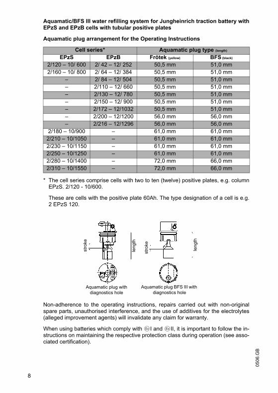
0506
.GB
8
Aquamatic/BFS III water refilling system for Jungheinrich traction battery withEPzS and EPzB cells with tubular positive plates
Aquamatic plug arrangement for the Operating Instructions
* The cell series comprise cells with two to ten (twelve) positive plates, e.g. columnEPzS. 2/120 - 10/600.
These are cells with the positive plate 60Ah. The type designation of a cell is e.g.2 EPzS 120.
Non-adherence to the operating instructions, repairs carried out with non-originalspare parts, unauthorised interference, and the use of additives for the electrolytes(alleged improvement agents) will invalidate any claim for warranty.
When using batteries which comply with I and II, it is important to follow the in-structions on maintaining the respective protection class during operation (see asso-ciated certification).
Cell series* Aquamatic plug type (length)
EPzS EPzB Frötek (yellow) BFS (black)
2/120 – 10/ 600 2/ 42 – 12/ 252 50,5 mm 51,0 mm2/160 – 10/ 800 2/ 64 – 12/ 384 50,5 mm 51,0 mm
– 2/ 84 – 12/ 504 50,5 mm 51,0 mm– 2/110 – 12/ 660 50,5 mm 51,0 mm– 2/130 – 12/ 780 50,5 mm 51,0 mm– 2/150 – 12/ 900 50,5 mm 51,0 mm– 2/172 – 12/1032 50,5 mm 51,0 mm– 2/200 – 12/1200 56,0 mm 56,0 mm– 2/216 – 12/1296 56,0 mm 56,0 mm
2/180 – 10/900 – 61,0 mm 61,0 mm2/210 – 10/1050 – 61,0 mm 61,0 mm2/230 – 10/1150 – 61,0 mm 61,0 mm2/250 – 10/1250 – 61,0 mm 61,0 mm2/280 – 10/1400 – 72,0 mm 66,0 mm2/310 – 10/1550 – 72,0 mm 66,0 mm
stro
ke
leng
th
stro
ke
leng
th
Aquamatic plug with diagnostics hole
Aquamatic plug BFS III with diagnostics hole

9
0506
.GBDiagrammatic view
Equipment for the water refilling system
1. Water tank
2. Level switch
3. Discharge point with ball valve
4. Discharge point with sole-noid valve
5. Charger
6. Sealing coupler
7. Closing nipple
8. Ion exchange cartridge with conductance meter and solenoid valve
9. Connection for untreated water
10. Charging lead
1. Design
The Aquamatic/BFS battery water refilling systems are used for automatically adjus-ting the nominal electrolyte level. Venting holes are provided for letting off the gaseswhich arise during charging. In addition to the optical level indicator, the plug systemsalso have a diagnostics hole for measuring the temperature and the electrolyte den-sity. All battery cells of the design series EPzS; EPzB can be equipped with the Aqua-matic/BFS filling systems. The water can be refilled by means of a central sealingcoupler through the hose connections in the individual Aquamatic/BFS plugs.
2. Application
The Aquamatic/BFS battery water refilling system is used in traction batteries forforklift trucks. The water refilling system is provided with a central water connectionfor the water supply. Soft PVC hose is used for this connection and for the hose con-nections for the individual plugs. The hose ends are put onto the hose connectionsleeves located on the T or < pieces.
3. Function
The quantity of water required in the refilling process is controlled by the valve locatedin the plug in combination with the float and the float rods. In the Aquamatic Systemthe existing water pressure at the valve turns off the water supply and ensures thatthe valve closes securely. When the maximum filling level is reached in the BFS sys-tem, the float and the float rods through a lever system close the valve with five timesthe buoyant force and consequently interrupt the water supply reliably.
at le
ast 3
m
9
0506
.GB
Diagrammatic view
Equipment for the water refilling system
1. Water tank
2. Level switch
3. Discharge point with ball valve
4. Discharge point with sole-noid valve
5. Charger
6. Sealing coupler
7. Closing nipple
8. Ion exchange cartridge with conductance meter and solenoid valve
9. Connection for untreated water
10. Charging lead
1. Design
The Aquamatic/BFS battery water refilling systems are used for automatically adjus-ting the nominal electrolyte level. Venting holes are provided for letting off the gaseswhich arise during charging. In addition to the optical level indicator, the plug systemsalso have a diagnostics hole for measuring the temperature and the electrolyte den-sity. All battery cells of the design series EPzS; EPzB can be equipped with the Aqua-matic/BFS filling systems. The water can be refilled by means of a central sealingcoupler through the hose connections in the individual Aquamatic/BFS plugs.
2. Application
The Aquamatic/BFS battery water refilling system is used in traction batteries forforklift trucks. The water refilling system is provided with a central water connectionfor the water supply. Soft PVC hose is used for this connection and for the hose con-nections for the individual plugs. The hose ends are put onto the hose connectionsleeves located on the T or < pieces.
3. Function
The quantity of water required in the refilling process is controlled by the valve locatedin the plug in combination with the float and the float rods. In the Aquamatic Systemthe existing water pressure at the valve turns off the water supply and ensures thatthe valve closes securely. When the maximum filling level is reached in the BFS sys-tem, the float and the float rods through a lever system close the valve with five timesthe buoyant force and consequently interrupt the water supply reliably.
at le
ast 3
m

0506
.GB
10
4. Filling (manual/automatic)
The batteries should be filled with battery water as soon as possible before the batterycharging comes to an end; this ensures that the refilled water quantity is mixed withthe electrolyte. In normal operation it is usually sufficient to fill once a week.
5. Connection pressure
The water refilling unit is to be operated in such a way that the water pressure in thewater pipe is between 0.3 bars and 1.8 bars. The Aquamatic System has an operatingpressure range of between 0.2 bars and 0.6 bars. The BFS system has an operatingpressure range of 0.3 bars to 1.8 bars. Deviations from the pressure ranges impairthe system's functional reliability. This wide pressure range permits three types of fil-ling.
5.1 Falling water
The height of the tank is chosen to suit whichever water refilling system is used. Forthe Aquamatic System the installation height is 2 m to 6 m and for the BFS systemthe installation height is 3 m to 18 m over the battery surface.
5.2 Pressurised water
The pressure-reducing valve in the Aquamatic System is set from 0.2 bars to 0.6 barsand from 0.3 bars to 1.8 bars in the BFS system.
5.3 Water Refill Trolley (serviceMobil)
The submergible pump located in the ServiceMobil's tank generates the necessaryfilling pressure. No difference in height is permitted between the standing level of theServiceMobil and the standing level of the battery.
6. Filling duration
The length of time needed to fill the batteries depends on the conditions under whichthe battery is used, the ambient temperatures and the type of filling and/or the fillingpressure. The filling time is approx. 0.5 to 4 minutes. Where filling is manual, the wa-ter feed pipe must be separated from the battery after filling.
7. Water quality
Only refilling water which conforms in quality to DIN 43530 part 4 may be used to fillthe batteries. The refilling unit (tank, pipelines, valves etc.) may not contain any kindof dirt which could impair the functional reliability of the Aquamatic/BFS plug. Forsafety reasons it is recommendable to insert a filter element (optional) with a max.passage opening of 100 to 300 µm into the battery's main supply pipe.

11
0506
.GB8. Battery hose connections
Hose connections for the individual plugs are laid along the existing electric circuit.No changes may be made.
9. Operating temperature
The temperature limit for battery operation is set at 55° C. Exceeding this temperaturedamages the batteries. The battery filling systems may be operated within a tempe-rature range of > 0° C to a maximum of 55° C.
CAUTION:Batteries with automatic water refilling systems may only be operated in roomswith temperatures > 0° C (as there is otherwise a danger that the systems mayfreeze).
9.1 Diagnostics hole
To be able to measure the acid density and temperature easily, the water refilling sys-tems must have a diagnostics hole with a 6.5 mm-diameter (Aquamatic plugs) or a7.5 mm-diameter (BFS plugs).
9.2 Float
Different floats are used depending on the cell design and type.
9.3 Cleaning
The plug systems may only be cleaned with water. No parts of the plugs may comein contact with soap or fabrics which contain solvents.
10. Accessories
10.1 Flow indicator
To monitor the filling process, a flow indicator can be inserted into the water feed pipeon the battery side. During the filling process, the paddlewheel is turned by the flowingwater. When the filling process ends, the wheel stops and this indicates the end ofthe filling process. (ident no.: 50219542).
10.2 Plug lifter
Only the appertaining special-purpose tool may be used to disassemble the plug sys-tems (plug lifter). The greatest of care must be employed when prising out the plug toprevent any damage to the plug systems.
11
0506
.GB
8. Battery hose connections
Hose connections for the individual plugs are laid along the existing electric circuit.No changes may be made.
9. Operating temperature
The temperature limit for battery operation is set at 55° C. Exceeding this temperaturedamages the batteries. The battery filling systems may be operated within a tempe-rature range of > 0° C to a maximum of 55° C.
CAUTION:Batteries with automatic water refilling systems may only be operated in roomswith temperatures > 0° C (as there is otherwise a danger that the systems mayfreeze).
9.1 Diagnostics hole
To be able to measure the acid density and temperature easily, the water refilling sys-tems must have a diagnostics hole with a 6.5 mm-diameter (Aquamatic plugs) or a7.5 mm-diameter (BFS plugs).
9.2 Float
Different floats are used depending on the cell design and type.
9.3 Cleaning
The plug systems may only be cleaned with water. No parts of the plugs may comein contact with soap or fabrics which contain solvents.
10. Accessories
10.1 Flow indicator
To monitor the filling process, a flow indicator can be inserted into the water feed pipeon the battery side. During the filling process, the paddlewheel is turned by the flowingwater. When the filling process ends, the wheel stops and this indicates the end ofthe filling process. (ident no.: 50219542).
10.2 Plug lifter
Only the appertaining special-purpose tool may be used to disassemble the plug sys-tems (plug lifter). The greatest of care must be employed when prising out the plug toprevent any damage to the plug systems.

0506
.GB
12
10.2.1 Clamping ring tool
The clamping ring tool is used to push on a clamping ring to increase the contact pres-sure of the hose connection on the plugs' hose couplings and to loosen it again.
10.3 Filter element
For safety reasons a filter element (ident no.: 50307282) can be fitted into the batte-ry's main supply pipe for supplying battery water. This filter element has a maximumpassage cross-section of 100 to 300 µm and is designed as a bag filter.
10.4 Sealing coupler
The water is supplied to the water refilling systems (Aquamatic/BFS) through a cen-tral supply pipe. This is connected to the water supply system at the battery chargingstation by means of a sealing coupler system. On the battery side a closing nipple(ident no.: 50219538) is mounted and the customer must place a sealing couplerconstruction on the water supply side (obtainable under ident. no.: 50219537).
11. Functional data
PS - self-sealing pressure: Aquamatic > 1.2 bars
BFS system none
D - rate of flow in the opened valve when the pressure is 0.1 bars: 350 ml/min
D1 - maximum permissible leakage rate in the closed valve when the pressure is at0.1 bars: 2 ml/min
T - permissible temperature range: 0° C to a maximum of 65° C
Pa - operating pressure range: 0.2 to 0.6 bars in the Aquamatic system andoperating pressure range: 0.3 to 1.8 bars in the BFS system.

13
0506
.GB
2 Jungheinrich traction batterie
Maintenance free Jungheinrich traction batterie with positive tubular platestype EPzV and EPzV-BS
Rating Data
1. Nominal capacity C5: See type plate
2. Nominal voltage: 2,0 Volt x No of cells
3. Discharge current: C5/5h
4. Rated temperature: 30° C
EPzV batteries are valve-regulated batteries with an immobilised electrolyte and whe-re a water refilling isn’t permitted during the whole battery life. Instead of a vent plugthere are valves used, who will be destroyed when they are opened.
When operating valve-regulated lead-acid batteries the same safety requirements asfor vented cells apply to protect against hazards from electric current, from explosionof electrolytic gas and in case of the cell container is damaged, from the corrosiveelectrolyte.
• Pay attention to the operation instruction and fix them close to the battery!• Work on batteries to be carried out by skilled personnel only!
• Use protective glasses and clothes when working on batteries!• Pay attention to the accident prevention rules as well as DIN EN 50272, DIN
50110-1!
• No smoking!• Do not expose batteries to naked flames, glowing embers or sparks, as it may
cause the battery to explode!
• Acid splashes in the eyes or on the skin must be washed with water. In case of accident consult a doctor immediately!
• Clothing contaminated by acid should be washed in water.
• Risk of explosion and fire, avoid short circuits!
• Electrolyte is highly corrosive!• In the normal operation of this batteries a contact with acid isn´t possible. If the
cell containers are damaged, the immobilised electrolyte (gelled sulphuric acid) is corrosive like the liquid electrolyte.
• Batteries and cells are heavy!• Ensure secure installation! Use only suitable handling equipment e.g. lifting gear
in accordance with VDI 3616.
• Dangerous electrical voltage!• Caution! Metal parts of the battery are always live. Do not place tools or other
metal objects on the battery!
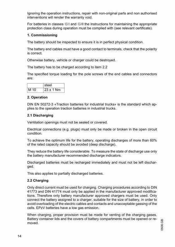
0506
.GB
14
Ignoring the operation instructions, repair with non-original parts and non authorisedinterventions will render the warranty void.
For batteries in classes I and II the instructions for maintaining the appropriateprotection class during operation must be complied with (see relevant certificate).
1. Commissioning
The battery should be inspected to ensure it is in perfect physical condition.
The battery end cables must have a good contact to terminals, check that the polarityis correct.
Otherwise battery, vehicle or charger could be destroyed.
The battery has to be charged according to item 2.2
The specified torque loading for the pole screws of the end cables and connectorsare:
2. Operation
DIN EN 50272-3 «Traction batteries for industrial trucks» is the standard which ap-plies to the operation traction batteries in industrial trucks.
2.1 Discharging
Ventilation openings must not be sealed or covered.
Electrical connections (e.g. plugs) must only be made or broken in the open circuitcondition.
To achieve the optimum life for the battery, operating discharges of more than 60%of the rated capacity should be avoided (deep discharge).
They reduce the battery life considerable. To measure the state of discharge use onlythe battery manufacturer recommended discharge indicators.
Discharged batteries must be recharged immediately and must not be left dischar-ged.
This also applies to partially discharged batteries.
2.2 Charging
Only direct current must be used for charging. Charging procedures according to DIN41773 and DIN 41774 must only be applied in the manufacturer approved modifica-tions. Therefore only battery manufacturer approved chargers must be used. Onlyconnect the battery assigned to a charger, suitable for the size of battery, in order toavoid overloading of the electric cables and contacts and unacceptable gassing of thecells. EPzV batteries have a low gas emission.
When charging, proper provision must be made for venting of the charging gases.Battery container lids and the covers of battery compartments must be opened or re-moved.
steel M 10 23 ± 1 Nm

15
0506
.GBWith the charger switched off connect up the battery, ensuring that the polarity is cor-rect (positive to positive, negative to negative). Now switch on the charger. Whencharging the temperature of the battery rises by about 15° C, so charging should onlybegin if the battery temperature is below 35° C. The battery temperature should be atleast +15°C before charging otherwise a full charge will not be achieved. Are the tem-peratures a longer time higher than +40° C or lower than +15° C, so the chargersneed a temperatures regulated voltage.
The correction factor is, in accordance with DIN EN 50272-1, -0,005 V/c and Kelvin.
Special instructions for the operation of batteries in hazardous areas.
This concerns batteries which are used in accordance with EN 50 014, DIN VDE 0170/ 0171 Ex I (in areas with a firedamp hazard) or Ex II (in potentially explosive areas).The attention pictograms has to be respected.
2.3 Equalising charge
Equalising charges are used to safeguard the life of the battery and to maintain itscapacity. Equalising charges are carried out following normal charging.
They are necessary after deep discharges and repeated incomplete recharges. Forthe equalising charges has to be used only the battery manufacturer prescribed char-gers.
Watch the temperature!
2.4 Temperature
A battery temperature of 30°C is specified as the rated temperature. Higher tempera-tures shorten the life of the battery, lower temperatures reduce the available capacity.45° C is the upper temperature limit and is not acceptable as an operating tempera-ture.
2.5 Electrolyte
The electrolyte is immobilised in a gel. The density of the electrolyte can not bemeasured.
3. Maintenance
Don’t refill water!
3.1 Daily
Charge the battery immediately after every discharge.
15
0506
.GB
With the charger switched off connect up the battery, ensuring that the polarity is cor-rect (positive to positive, negative to negative). Now switch on the charger. Whencharging the temperature of the battery rises by about 15° C, so charging should onlybegin if the battery temperature is below 35° C. The battery temperature should be atleast +15°C before charging otherwise a full charge will not be achieved. Are the tem-peratures a longer time higher than +40° C or lower than +15° C, so the chargersneed a temperatures regulated voltage.
The correction factor is, in accordance with DIN EN 50272-1, -0,005 V/c and Kelvin.
Special instructions for the operation of batteries in hazardous areas.
This concerns batteries which are used in accordance with EN 50 014, DIN VDE 0170/ 0171 Ex I (in areas with a firedamp hazard) or Ex II (in potentially explosive areas).The attention pictograms has to be respected.
2.3 Equalising charge
Equalising charges are used to safeguard the life of the battery and to maintain itscapacity. Equalising charges are carried out following normal charging.
They are necessary after deep discharges and repeated incomplete recharges. Forthe equalising charges has to be used only the battery manufacturer prescribed char-gers.
Watch the temperature!
2.4 Temperature
A battery temperature of 30°C is specified as the rated temperature. Higher tempera-tures shorten the life of the battery, lower temperatures reduce the available capacity.45° C is the upper temperature limit and is not acceptable as an operating tempera-ture.
2.5 Electrolyte
The electrolyte is immobilised in a gel. The density of the electrolyte can not bemeasured.
3. Maintenance
Don’t refill water!
3.1 Daily
Charge the battery immediately after every discharge.
0506
.GB
16
3.2 Weekly
Visual inspection after recharging for signs of dirt and mechanical damage.
3.3 Quarterly
After the end of the charge and a rest time of 5 h following should be measured andrecorded:
• the voltages of the battery
• the voltages of every cells
If significant changes from earlier measurements or differences between the cells orbloc batteries are found, further testing and maintenance by the service departmentshould be requested.
3.4 Annually
In accordance with DIN VDE 0117 at least once per year, the insulation resistance ofthe truck and the battery must be checked by an electrical specialist.
The tests on the insulation resistance of the battery must be conducted in accordancewith DIN 43539-1.
The insulation resistance of the battery thus determined must not be below a value of50 Ω per Volt of nominal voltage, in compliance with DIN EN 50272-3.
For batteries up to 20 V nominal voltage the minimum value is 1000 Ω.
4. Care of the battery
The battery should always be kept clean and dry to prevent tracking currents. Clea-ning must be done in accordance with the ZVEI code of practice «The Cleaning ofVehicle Traction batteries».
Any liquid in the battery tray must be extracted and disposed of in the prescribed man-ner.
Damage to the insulation of the tray should be repaired after cleaning, to ensure thatthe insulation value complies with DIN EN 50272-3 and to prevent tray corrosion. If itis necessary to remove cells it is best to call our service department for this.
5. Storage
If batteries are taken out of service for a lengthy period they should be stored in thefully charged condition in a dry, frost-free room.
To ensure the battery is always ready for use a choice of charging methods can bemade:
1.a quarterly full charging like charge as in point 2.2. If any consumer is connectedwith, e.g. measure or controlling systems, it can be, that this charging is necessaryevery 14 days.
2. float charging at a charging voltage of 2.25 V x the number of cells.
The storage time should be taken into account when considering the life of the batte-ry.

17
0506
.GB6. Malfunctions
If malfunctions are found on the battery or the charger our service department shouldbe called without delay. The measurements taken in point 3.3 will facilitate fault fin-ding and their elimination.
A service contract with us will make it easier to detect and correct faults in good time.
Back to the manufacturer!
Batteries with this sign must be recycled.
Batteries which are not returned for the recycling process must bedisposed of as hazardous waste!
We reserve the right make technical modification.
7.Type plate, Jungheinrich traction battery
* CE mark is only for batteries with a nominal voltage greater than 75 volt.
Item Designation Item Designation1 Logo 8 Recycling symbol2 Battery designation 9 Dustbin/material3 Battery type 10 Nominal battery voltage4 Battery number 11 Nominal battery capacity5 Battery tray number 12 Number of battery cells6 Delivery date 13 Battery weight7 Battery manufacturer's logo 14 Safety instructions and warnings
Typ1
Type
Nennspannung5
Nominal Voltage
Hersteller9
Manufacturer
Kapazität 6
Capacity
Zellenzahl7
Number of CellsBatteriegewicht min/max 8
Battery mass min/max
Serien-Nr.3
Serial-Nr.Lieferanten Nr. 4
Supplier No.
Baujahr 2
Year of manufacture
Jungheinrich AG, D-22047 Hamburg, Germany
5
Pb Pb
2/3 651113
1
14
41012
7
8
9
17
0506
.GB
6. Malfunctions
If malfunctions are found on the battery or the charger our service department shouldbe called without delay. The measurements taken in point 3.3 will facilitate fault fin-ding and their elimination.
A service contract with us will make it easier to detect and correct faults in good time.
Back to the manufacturer!
Batteries with this sign must be recycled.
Batteries which are not returned for the recycling process must bedisposed of as hazardous waste!
We reserve the right make technical modification.
7.Type plate, Jungheinrich traction battery
* CE mark is only for batteries with a nominal voltage greater than 75 volt.
Item Designation Item Designation1 Logo 8 Recycling symbol2 Battery designation 9 Dustbin/material3 Battery type 10 Nominal battery voltage4 Battery number 11 Nominal battery capacity5 Battery tray number 12 Number of battery cells6 Delivery date 13 Battery weight7 Battery manufacturer's logo 14 Safety instructions and warnings
Typ1
Type
Nennspannung5
Nominal Voltage
Hersteller9
Manufacturer
Kapazität 6
Capacity
Zellenzahl7
Number of CellsBatteriegewicht min/max 8
Battery mass min/max
Serien-Nr.3
Serial-Nr.Lieferanten Nr. 4
Supplier No.
Baujahr 2
Year of manufacture
Jungheinrich AG, D-22047 Hamburg, Germany
5
Pb Pb
2/3 651113
1
14
41012
7
8
9

0506
.GB
18
0506
.GB
18