v=- - مرحبا بكم في موقع د. عبدالله ... fogler-4th ed.… · batch reactors...
TRANSCRIPT

Sec. 3.4 Present Slatus of Our Approach to Reactor Siz~ng and Design 99
TABLE 3-2. DESIGN EQUATIONS
Diflerential Algebmic lntegml Form Fonn Form
Batch N 4 0 F r - r A V (2-6)
The design Backmix equations v=- tCSTR)
F*" ((2.1 3) - FA
Tubular (2-15) dX ( PFR ) V=F,,( - (?-!6j
. n - r ,
Packed bed (2-17) dX
WBR) W = Fhu (2-18)
A
With these additional relationships, one observes that if the rate law is given and the concentrations can be expressed as a function of conversion. r k ~ n it7
fact we have - r A as a ft~ncrion of X and rhis i s nll ,ha1 is needed io eraluore ?he design .equarions. One can use either the numericai techniques described in Chapter 2, or. as we shall see in Chapter 4, a table of integrals, andlor software programs le.g.. Polymath).
Now that we have shown how the rate law can be expressed as a function of concentrations. we need only express concentration as a function of conversion in order to carry out calculations similar to those presented in Chapter 2 to size reactors. If the rate law depends on more than one species. we must relate the concentrations of the different species to each other. This relationship is most easily established with the aid of a stoichiometric table. This table presents the stoichiometric relationships between reacting molecules for a single reaction. That is. it tells us how many rnolecuIes of one species will be formed during a chemical reaction when a given number of molecules of snorher species disap- pears. These ~Iationships will be developed for the general reac~ion
Recall that we have already used stoichiametr-jl to relate the reIatrve rates of reaction for Equation (2-1 ):
T h ~ c s~oich~ometnc ~lal lonship relating
reaction rates W I I I he used in Pan 1 of
Chapter 4.
100 Rate Laws and Stoichiometrj Chap. :
Components of the stoichiornettic table
In formulating our stoichiornetsic table, we shall take species A as o u ~ basis of calculation (i.e.. limiting reactant) and then divide through by the stoi- chiometric coefficient of A.
in order to put everything on a basis of "pet mole of A." Next, we develop the stoichiometric relationships for reacting species thal
give the change in the number of moles of each species li.e.. A. B, C. and D).
3.5 Batch Systems
Batch reactors are primarily used for the praduction of specialty chemicals and to obtain reaction rate data in order to determine reaction mte laws and rate law parameters such as k, the specific reaction rate.
Figure 3-4 shows an artist's rendition of a batch system in which we will carry ot~t the reaction given by Equation (2-2). At time t = O, we will open the reactor and place a number of moles of species A, B. C, D, and I (NAO, Ng0, N,,, N,, and N,, respectively) into the reactor.
Species A is our basis of calculation, and NAo is the number of moles of A initially present in the reactor. Of these. NA& moles of A are consumed in the system as a result of the chemical reaction, leaving (NAo - NA& moles of A in the system. That is, the number of moles of A remaining in the reactor after a conversion X has been achieved is
We now will use conversion in this fashion to expresc the number of moles of B, C, and D in terms of conversion.
To determine the number of moles of each species remaining after N,,X moles of A have reacted, we form the stoichiometric table (Table 3-3). This stoichiornetric table presents the foIlowing information:
Column I: the particular species Column 2: the number of moles of each species initially present Column 3: the change in the number of mojes brought about by reaction CoIumn 4: the number of moles remaining in the system at time t
To calculate the number of moles of species B remaining at time t , we recall that at time t the number of moles of A that have reacted is N A o X . For every mole of A that reacts, bla moles of B must react; therefore, the total: number of moles of B that have reacted is
moles B reacted = reacted - rnoIes A reacted moles A reacted

Sec. 3.5 Batch Systems
Figure 3.4 Batch reactor. (Schematic with permission by Renwahr.1
TABLE 3-3. STOICH~OMETRIC TMLE FOR A BATCH SYFTEM
It~irtuil~ CItcrrrge Rennining Specirs (mol) (moll (moll
A N%o - X W, = NAG - ,V+,,,XI
Because B is disappearing from the system, the sign of the "change" is nega- tive. NBO is the number of moles initially in the system. Therefore, the number of moles of B remaining in the system. N, , at a time f, is given in the Iast col- umn of Table 3-3 as
102 Rate Laws and Stoichiomefry Chap. 3
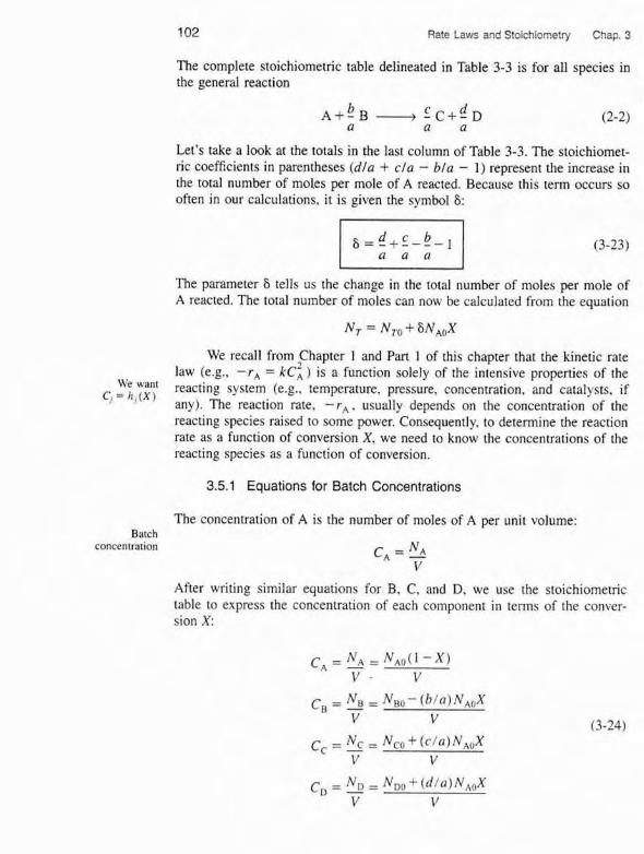
The complete stoichiometric tabIe delineated in Table 3-3 is for a11 species in the general reaction
Let's take a took at the totals in the last column of Table 3-3. The stoichiomet- ric coefficients in parentheses (dla -k c/a - bla - 1) represent the increase in the total number of moles per mole of A reacted. Because this term occurs so often in our calculations, it is given the symbol 8:
The parameter 6 tells us the change in the total number of moles per mole of A reacted. The total number of moles can now be calculated from the equation
We recall from Chapter 1 and Part 1 of this chapter that the Enetic rate law (e.g., - r , = kc:) is a function solely of the intensive properties of the
we reacting system (e-g.. temperature, pressure, concentration, and catalysts, if C, = " , [ X I any). The reaction rate, - r , . usually depends on the concenrration of the reacting species raised to some power. Consequently, to determine the reaction rate as a function of conversion X, we need to know the concentrations of the reacting species as a function of conversion.
3.5.1 Equations for Batch Concentrations
The concentration of A is the number of moles of A per unit volume: Batch
concentration N C , = 1 V
After writing similar equations for B. C, and D. we use ;the stoichiometric table to express the concentration of each component in terns of the conver- sion X:

Sec. 3.5 Batch Systems 103
We further simplify these equations by defining the parameter O, , which allows us to factor N,, in each of the expressions for concentration:
C, = [OD + ( d / a ) X ] NDO
v , with OD = - NAQ
we to 1% now need only to find volume as a function of conversion to obtain the ohlain C, = I I , ( X ) .
species concentration as a function of conversion.
3.5.2 Constant-Volume Batch Reaction Systems
Some significant simplifications in the reactor design equations are possible when the reacting syrtem undergoes no change in volume as the reaction progresses. These systems are called constant-volume. or constant-density, because of the invariance of either voIume or density during rhe reaction pro- cess. This situation may arise from several causes. In gas-phase batch systems, the reactor is usually a sealed constant-volume vessel with appropriate instsu- ments to measure pressure and temperature within the reactor. The volunle within this vessel is fixed and will not change. and is therefore a constant-\.olume system (V = V,,). The laboratory bomb calorimeter reactor i s a typical example of this type of reactor.
Another example of a constant-volume gas-phase isothermal reaction occurs when the number of moles of products equals the number of moles of reactants. The water-gas shtft reaction. important in coal gasification and many other processes, is one of these:
In this reaction, 2 mol of reactant forms 2 mol of product. %'hen the number of reactant molecules forms an equal number of product molecules at the sm~ie temperature and pressure, the volume of the reacting mixture will not change if the conditions are such that the ideal gas law is applicable. Qr if the com- pressihiliry factors of the products and reactants are appmximateIy equal.
For liquid-phase reactions taking place in solution. the solvent usually dominates the situarron. As a rewlt. changes in the denrity of the rolute do not

104 Rate Laws and Stolchiometry Chaw
affect the overall density of the solution significantly and therefore i t is essen tially a constant-volume reaction process. Most liquid-phase organic reaction do not change density during the reaction and represent still another case t which the constant-volume simplifications apply. An important exception t this general rule exists for polymerization processes.
For the constant-volume systems described earlier, Equation (3-25) ca be simplified to give the following expressions relating concentration and con version:
Concentration as a function of CB = NAo f ( N ~ ~ / N ~ ~ ) - (b/a)Xl- - 40 [@,-(blalXl = & ( O B - : X ) (
conversion when v~ vn no volume chanee
occurs with reactron CC = NAO
[ ( N , , / ~ , , 3 + (c/a)Xl yo
To summarize for liquid-phase reactions (or as we will soon see for isotherma and isobaric gas-phase reactions with no change in the total number of moles) we can use a rate law for reaction (2-2) such as -r, = kACACB to obtair
l-----l - r , =AX)% that is,
- r , = kCACB = kc:*( 1 - X)
Substituting for the given parameters k. CAO, and OB, we can now use the tech x niques in Chapter 2 to size the CSTRs and PFRs for liquid-phase reactions.
Example 3-2 Expressing = hj(X) for a Liquid-Phase Reaction
Soap consists of the sodium and potassium salts of various fatty acids such as oleic stearic, patmitic, lauric, and my~isttc acids. The saponification for the formation o soap from aqueous caustic soda and glyceryl stearate is
Letting X represent the conversion of sodium hydroxide (the moles of sodiurr hydroxide reacted per mole of sodium hydroxide initially present), set up a stoichio metric table expressing the concentration of each species in terms of its initial con centration and the conversion X.

Sec 3.5 Batch Systems 1 05
Choosing a bacis of calculation
Stoichiomerric table (batch)
Because we are taking sodlurn hydroxide as our basis, we divide through by the stoichiometric coefficient of sodium hydmx~de to put the reaction expression in the form
We may then perform the calculations shown in Table E3-2.1. Because this ir a liquid-phase reaction, the density p is considered to be constant; therefore, V = I.', .
TABLE E3-2.1. S~Y)ICHIOMETRIC TABLE FOR LIQUID-PHASE SOAP REALTION
Specie1 Symbol Initially C h a n ~ e Remaining Concentration
NaOH A NAO -maax N ~ o ( l - x ) C ~ o ( 1 - x )
Water (inen) I % - - Nto &lo Af T,, 0 NT = NTO
/ Example 3-3 What i s Be Limiting Reactant?
Waving set up the stoichiometric table i n Example 3-2, one can now readily use i t to calculate the concentrations at a given conversion. If the initial mixrute consists solely of sodium hydroxide at a concentmtion of 10 rnol/dmJ (i.e., 10 rnol/L or 10 kmollrn3 5 and of plyceryl stearate at a concentration of 2 molldm3, what is the con- centration of glycerine when the co'nversion of sodium hydroxide i s (a) 20% and (b) 90%?
[ Solution
Only the reactants NaOH and (Cl,H35COO)3C3FE5 are initidly present: therefore. 0, = 0, = 0.

Rate Laws and Stoichiometry Chap. 3
1 (a) For 20% conversion of NaOH:
(h) For 909 conversion of NaOH:
] Let us find C,:
3,6 Flow Systems
The bass or calculal'on chould
he Ihe limirinf reaclant.
The form of the stoichiometric table for a continuous-flaw system (see Figure 3-5) is vir~ually identical to that for a batch system (Table 3-3) except (hat we replace N!o by q;:, and N, by F, (Table 3-4). Taking A as the basis. divide Equation i2-1) through by the stoichiornetric coefficient of A to obtain
Oops!! Negative concentration-impossible! What went wrong? Ninety percent conversion of NaOH is not possible. because glyceryl stearate
is the limiting reactant. Consequently, all the glyceryl stearate i s used up before 90% of the NaOH could be reacted. It i s irnprtant to choose the Ilrnlting reactant as the basis of calcuIation.
Entering
F~~ 1
Figure 3-5 Flou- reactor.

Sec. 3.6 flow Systems 107
F ~ e d Rate lo Change wirhin Reacfox Reactor Eflueni Rote fmm Reocro r
Species (molltime) (molltirm) (mu1 {time)
A F A 0 - FAOX FA = FA0 ( I - X)
B F~~ = @ B ~ A O -- b FAOX a
Sro~chiometric table (Row) C Fco " @cFm : FAOX
where
and Bc, OD. and 8, are defined similarIy.
3.6.1 Equations for Concentrations in Flow Systems
For a flow system, the concentration C, at a given point can be determined from the molar flow rate F A and the volumetric flow rate v at that point:
Definition of concentration for a
flow system
Units of u are typically given in terms of liters per second, cubic deci- meters per second, or cubic feet per minute. We now can write the concenrra- tions of A, B, C, and D for t h e general reaction given by Equation (2-21 in terms of their respective entering molar flow rates (F,,, F R O . F,,. F,,), the conversion X. and the volumetric flow rate, v .
108 Rate Laws and Stoichiometry Chap. :
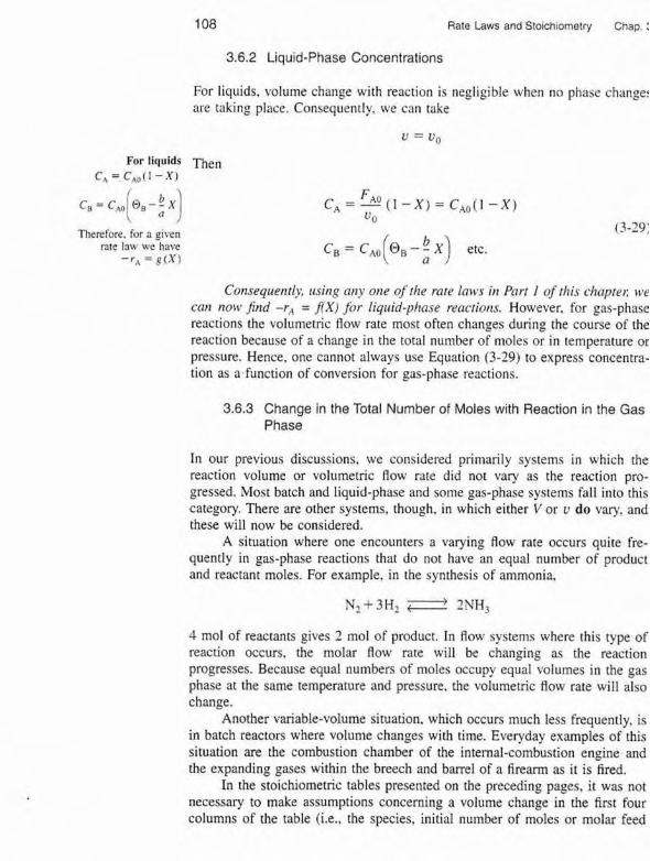
3.6.2 Liquid-Phase Concentrations
For liquids, volume change with reaction is negligible when no phase changer are taking place. Consequently, we can take
For IfquidS Then Cq =C*o(I - X I
Therefore, for a given rate law we have
- r A = ( X ) C,=C,, @,--X etc. ( :I
Consequentiy, btsing arty one oj' the rare lows in Port I of this chapr~l; cve con now Jnd -r, = AX) for liquid-phase reactions, However, for pas-phase reactions the volumetric flow rate most often changes during the course of the reaction because of a change in the total number of moles or in temperature or pressure. Hence, one cannot always use Equation (3-29) to express concentra- tion as a function of conversion for gas-phase reactions.
3.6.3 Change in the Total Number of Moles with Reaction in the Gas Phase
In our previous discussions, we considered primarily systems in which the reaction volume or volumetric flow rate did not vary as the reaction pro- gressed. Most batch and liquid-phase and some gas-phase systems fall into this category. There are other systems, though, in which either V or u do vary. and these will now be considered.
A situation where one encounters a varying flow rate occurs quite fre- quently in gas-phase reactions that do not have an equal number of product and reactant moles. For example, in the synthesis of ammonia,
4 rnol of reactants gives 2 mol of product. In ffow systems where this type of reaction occurs, the molar flow rate will be changing ar the reaction progresses. Because equal numbers of moles occupy equaI volumes in the gas phase at the same temperature and pressure. the volumetric flow rate wilI also change.
Another variable-volume situation, which occurs much less frequently, is in batch reactors where volume changes with time. Everyday examples of this situation are the combustion chamber of the internal-combustion engine and the expanding gases within the breech and barrel of a fiream as it is fired.
In the stoichiometric tables presented on the preceding pages, it was not necessary to make assumptions concerning a volume change in the first four coIumns of the table (i.e.. the species, initial number of moles or molar feed

See. 3.6 Flow Systems 109
rate, change within the reactor, and the remaining number of moles or the molar effluent rate). All of these columns of the stoichiometric table are inde- pendent of the volume or density. and they are irfenticnl for constant-volume (constant-density) and varying-volume (varying-density) situations. Only when concentration is expressed as a function of conversion doer variable dens~ty enter the picture.
Batch Reactors with Variable Volume Although variable volume batch reac- tors are seldom encountered because they are usually solid steel containers. we wiIl develop the concentrations as a function of conversion because (1) they have been used to collect reaction data for gas-phase reactions, and (2) the development of the equations that express volume as a function of conversion w~i l facilitate analyzing flow systems with variable volumetric flow rates.
Individual concentrations can be determined by expressing the volume V for a batch system, or volumetric flow rate v for a flow system, as a function of conversion using the following equation of state:
Equation of state PV = ZN,RT (3-30)
i n which V = volume and N , = total number of moles as before and
T = temperature. K P = total pressure, atm &Pa; t atm = 101.3 kPa) Z = compressibility factor
R = gas constant = 0.08206 dm" aatmtmol - K Thi s equation is valid at any point i n the system at any time t . At time
r = 0 (i.e., when the reaction is initiated). Equation 13-30) becomes
Dividing Equation (3-30) by Equation (3-3 1 ) and rearranging yields
We now want to express the volume V as a function of the conversion X. Recalling the equation for the total number of moles In Table 3-3,
where
S = Change in total number of moles Mole of A reacted

110 Rate Laws and Stoichiometry Chap. 3
We divide Equation (3-33) through by N,:
Then
- 'T = I + E X (3-34) NTQ
Rc[a l i~nsh i~ between where yAo is the mole fraction of A initially present, and where 8 and e
E = ~ + n - ~ - ~ ) ~ = J b A o ~ N, (3-351
Equation (3-35) holds for both batch and flow systems. To interpret E, let's rearrange Equation (3-34)
Interwiati*n of at complete conversion, (i .e.. X = I and N , = NTf)
- - Change in total number of moles for complete conversion Total moles fed
If all species in the generalized equation are in the gas phase. we can substitute Equation (3-34) with Equation (3-32) to arrive at
In the gas-phase systems that we shall be studying, the temperatures and pres- sures are such that the compressibility factor will not change significantly dur- ing the course of the reaction: hence Z,=Z. For a hatch system, the volume of gas at any time I is
Volume of gas for a variable volume
batch reaction
Equation (3-38) applies only to a 1~arinble-1~r)fu?nr hatch reactor, where one can now substitute Equation (3-38) into Equation (3-25) to express r, =PX). HOW- ever, if the reactor is a rigid steel container of constant volume, then of course

Sac. 3.6 FIOW Systems Ill
V = V,. For a constant-volume container, V = I],, and Equation 13-38] can be used to calculate the gas pressure inside the reactor as a function of temper- ature and conversion.
Flow Reactors with Variable Volumetric Flow Rate. An expression sirnifar to Equation (3-38) for a variable-volume batch reactor exists for a variable-vol- ume fiow system. To derive the concentrations of each species in terns of con- version for a variable-volume flew system, we shall use the relationships for the total concentration. The total concentration, CT. at any point in the reactor is the total molar flow rate, 6, divided by volumetric flow rate v [cf. Equation (3-27)J. In the gas phase, the total concentration is also found from the gas law. Cr = PER1 Equating these two ~Iationships gives
P c , = F ' = - v ZRT
At the entrance to the reactor,
Taking the ratio of Equation (3-40) to Equation (3-39) and assuming neg- ligible changes in the compressibility factor, we have upon rearrangement
We can now express the concentration of species j for a flow system in terms of its flow rate, 5, the temperature, T, and total pressure. P.
Use th~s form for membrane reactop
(Chapter 4) and for rnuEiipfe
reaction.: (Chapter 61
The total moiar flow rate is just the sum of the molar flaw rates of each of the species in the system and is
11 2 Rate Laws and Stoichiometry Chap
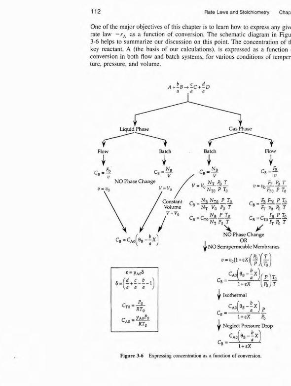
One of the major objectives of this chapter is to learn how to express any giv~ rate law - r , as a function of conversron. The schematic diagram in Figu 3-6 helps to summarize our discussion on this point. The concentration of t l key reactant. A (the basis of our calculations), is expressed as a function conversion in both flow and batch systems, for various conditions of temper ture. pressure, and voIume.
Flow
v NO Phase Change
J NO Phase Change
OR NO Sern~penneable Membranes
4 Isothermal
Ifr Neglect Pressure Drop
c, = c*,(e, - $ x )
1 +EX
Flgure 3-6 Expressing concentration as a function of conversion.

Gns-phase volumetric flow
rate
Sec. 3.6 Flow Svsterns 113
We see that conversion is not used in this sum. The molar flow rates, F,, are found by solving the mole balance equations. Equation 11-42) wiIl be used for measures ohher than conversion when we discuss membrane reactors (Chapter 4 Pan 2) and multiple reactions (Chapter 6). We wiil use this form of the concenfration equation for multiple gas-phase reactions and for membrane reactors.
Now let's express the concentration in terms of conversion for gas flow systems. From Table 3 4 the total niolx Row rate can be written in terms of conversion and is
FT = F f f l + F,40 8 X 13-43}
Substituting for F , in Equation (3-41) gives
U = U o FTO + f,, 5X P, T Fm (F) E
The concentration of species j is
The molar flow rate of species j is
where v, is the stoichiometric coefficient, which is negative for reactants and positive for products. For example, for the reaction
v, = -1, v, = -bla, v, = c / a . v D = d / a , and O j = FplFAw
Substituting for v using Equation (3-42) and for F,, we have
Gasphase concmtration as a
function of conversion
114 Rate Laws and Stoichiometry C h a ~ . 3
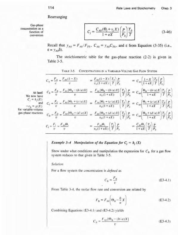
Rearranging
Recall that yAo = F,,/F,, , C,, = y,,Cm, and E from Equation (3-35) (i.e., E = ?'A06).
The stoichiornettic table for the gas-phase reacrion (2-2) is given jn Table 3-5.
Wc now have v
C, = h , ( X , and - FC - F,, I (-), + ( r ln)Xl - - FA(, + ( I . / N J X I TO P @ , + ( r / a ) X T, p
c - y - - r , = R ( X ) u V ~ ( I + ~ X ) ( ) I + E X )F[g)
for variable-volume gas-phase reaction< -FD - F 4 ~ [ 8 ~ C ( d ! u ) X l = Q, f ( d l a ) X 7, p D - - -
L'
Exumple 3 4 Maniprlatiotr of the Equation for C, = hj (XI
1 Show under H hat condirions and manipulation the expression for CB for a gas Row system reduces to that given in Tahle 3-5.
Soll~tinrr
For a flow system the concentration is dcj i~~cd as
From Tahle 3-3, the molar Row raIe and conversion are related by
Cornhininy Eqi~ations (E.1-4.1) and (E3-4.2) yields

Sec. 5.6 Flow Systems
This equalion for u Using Equation (3-45) gives us is only for a gas- I
phase reaction I
to substitute for the volumetric flow rate gives
( which is identical to the concentration expression for a variable-volume batch reactor.
I Example 3-5 Determining Cj = hi (XI for a Gas-Phase Reaction
A mixture of 28% SO, and 72% air is charged to a flow reactor in which SO, is oxidized.
2so2 + 0, ----4 2S0,
First. set up a stoichiometric table using only the symbols (i.e.. O , , F , ) and then pzpare a second stoichiometric table evaluating numericalry as many symbols as possible for the case when the total pressure is 1485 kPa (14.7 atm) and the temper- ature is constant at 227'C.
Taking SO: as the basis of calculation. we divide the reaction through by the stoi- chiometric cmfficient of Our chosen basis of calculation:
I SOz + f02 - SO?
The initial stoichiometric table is given as Table E3-5.1. Initially, 72% of the total number of moles i s air containing (21% O2 and 79% N 2 ) along with 2 8 8 SO?.
From the definition of conversion, we ~ubstitute not only for the molar flow rate of SO, (A ) in tenns of conver~ion hut a150 for the volumetric flow rate as a function of conversion.

116 Rate Laws and Stoichiometry Chap. ;
Species S m h f Initially Chmge Remnining
so2 A FA, - F A U X F A F , = F , , , ( l - X )
NegIecting pressure
drop. P = Po
isotherma[ operation, T = To
SO, C 0 +FAfiX Fc = FAOX
Recalling Equation (3-451, we have
Neglecting pressure drop in the reaction. P = P,, yields
If the reaction is also carried out isothermally. T = To . we obtain
The concentration of A initially is equal ta the mole fraction of A initially multiplied by the total concentration. The total concentration can be calculated from an eaua- tion of state such as the ideal gas taw. Recall that y~~ = 0.28, To = 500 K. and Po= 1485 Wa.
Sec, 3.6 Flow Systems
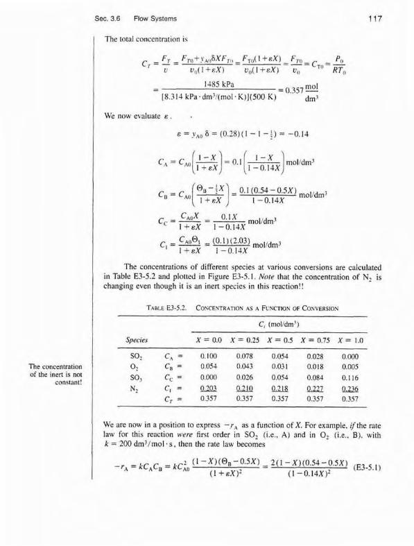
I The total concentration i s
The concentration of the inert is nor
constant!
I We now ewlunte e . .
The concentntions of different species at various conversions are calculated in Table E3-5.2 and plotted in Figure E3-5.1. Note that the concentntion of N2 is changing even though i t is an inert species in this reaction!!
TABLE E3-5.1. COXCESTRATIOY 45 A F U Y ~ I O N OF CONVERSIOS
C, (molldm')
Species X=O.O X = 0 . 2 5 X = 0 . 5 X=8.75 X = 1.0
SO, C, = 0.100 0078 0.054 0.028 0.000
a? C, = 0.054 0.043 0.031 0.018 0.005 SO, C, = 0.000 0.026 0.054 0.084 0.1 16
We are now in a position to express - r , as a function of X. For example, ifthe nte law for this reaction were first order in SO, (i.e., A) and in 0, (i+e., S), with k = 280 dm3/mol - s , then the rate law becomes

118 Rate Laws and Stoichiometry Chap. 3
Nore: Because the voiurnetic Row rate varies with conversion, the
concentration of inert5 (N2) i s not
constant.
Now use tech- niques presented
i n Chapter 2 to size reaclors.
Figure E3-5.1 Concentration as a function of conversion.
- 1 Taking the reciprocal of - r , yields
We see that we could ~ite a variety of combinations of i s o r h e m i reactors using the
1 techniques discussed in Chapter 2.
Thus far in this chapter, we have focused mostly on irreversible reac- tions. The procedure one uses for the isothermal reactor design of reversible reactions is virtually the same as that for irreversible reactions. with one nota-
Need to first cllrculate xr ble exception. First calculate the maximum conversion that can be achieved at
the isothermal reaction rernperature. This value is the equilibrium conversion. In the following example it will be shown how our algorithm for reactor design is easily extended to reversible reactions.
I Example 3-6 Calcuhting the Equilibrium Conversion
The reversible gas-phase decomposition of nitrogen tetroxide, N,O,. to nitrogen dioxide, NO2,

Sec. 3.6 flm Systems f19
is to be carried out at constant temperature. The feed consists of pure NzO, at 340 K and 202.6 kFa (2 am). The concentration equilibrium constant. Kc. at 340 K is 0.1 molldm". (a) Calculate the equilibrium conversion of N,O, in a constant-volume batch
reactor. (b) CalcuIate the equilibrium conversion of N20, in a flow reactor. (c) Assuming the reaction is elementary, express the rate of reaction soleIy as a
function of conversion for a Row system and for a batch system. Id) Determine the CSTR volume necessary to achieve 80% of the equilibrium
conversion.
At equilibrium the concentrations of the reacting species are relaled by the relation- ship dictated by thermodynamics [see Equation (3-10) and Appendix C]
( (a, Batch system-constant volume, V = Y o . See %Me E3-6.1.
Living Example Problea
For batch systems C, = N, / V ,
C - !'~oPo , ( I ) ( ? atm) *' RT,, (0.082 atm.dm3/rnol +K)(340 K)
At equilibrium. X= J,,. and we substitute Equations (E3-6.2) and (E3-6.31 illto Equation (E3-6. I ) .

120 Rate Laws and Stoichiometry Chap.
There is a PoIymath tutorial in the
summary Notes of Chapter 1
We will use Polymath to solve for the equilibnum conversion and let xeb repfese the equilibrium conversion in a constant-volume batch reactor. Equation (E3-6.m written in Polymath format becomes
f (xeb) = xeb - [kc*(l - xeb)/(?*cao) J "0.5
The Polymath program and solution are given in Table E3-6.1.
When looking at Equation (E3-6.4). you probably asked yourself. "Why not use tl quadratic formula to solve for the equilibnum convesston in both batch and flo syrterns?' That is,
I Batch: X, = -[(-I + JF + l6CAOIKc)/(CA,J K c ) ] 8
[(E- I ) + J(G- I ) ~ * ~ I F + ~ C ~ ~ / K ~ ) I Flow: X, =
2 ( ~ + 4 C A o l K c )
The answer is that future problems will be nonlinear and require Polymath solution: and I wanted to increase the reader's ease in using Polymath.
TABLE E3-6.2. POLYMATH PROGRAM AND SOLLTEOY FOR BOTH BATCH 4x0 FLOW SYSTEMS
m i a b l e f (XI Ini G u w Xeb 4.078E-08 0 . 5 Xe f 2.622E-10 0 . 5 Kc 0.1
NLES Report Wenewt)
Nonlinear equations . I: f(Xeb) = Xeb-(Kcm(l -Xeb)l(4"Cao))"O.S = 0 i i : f(Xef) = Xef-(Kc'(1-Xef)'(t+eps*Xef)I(CCao)~.S = O
Explicit equations i - ] Kc=O.l if.; Cao=0.07174 :3; eps= 1
The equilibrium conversion in a constant-volume batch reactor is