v2.1 integrators handbook - linuxcnc.orgcontents v 7 hal tutorial 48 7.1 before we start . . . . . ....
TRANSCRIPT
V2.1 Integrators Handbook
June 25, 2007

i
The EMC Team
This handbook is a work in progress. If you are able to help with writing, editing, or graphicpreparation please contact any member of the writing team or join and send an email to [email protected].
Copyright (c) 2000-6 LinuxCNC.org
Permission is granted to copy, distribute and/or modify this document under the terms of theGNU Free Documentation License, Version 1.1 or any later version published by the Free SoftwareFoundation; with no Invariant Sections, no Front-Cover Texts, and one Back-Cover Text: "This EMCHandbook is the product of several authors writing for linuxCNC.org. As you find it to be of value inyour work, we invite you to contribute to its revision and growth." A copy of the license is included inthe section entitled "GNU Free Documentation License". If you do not find the license you may ordera copy from Free Software Foundation, Inc. 59 Temple Place, Suite 330 Boston, MA 02111-1307

Contents
I Introduction 1
1 The Enhanced Machine Control 2
1.1 Introduction . . . . . . . . . . . . . . . . . . . . . . . . . . . . . . . . . . . . . . . . . . . 2
1.2 The Big CNC Picture . . . . . . . . . . . . . . . . . . . . . . . . . . . . . . . . . . . . . . . 2
1.3 Computer Operating Systems . . . . . . . . . . . . . . . . . . . . . . . . . . . . . . . . . 3
1.4 History of the Software . . . . . . . . . . . . . . . . . . . . . . . . . . . . . . . . . . . . . 3
1.5 How the EMC2 Works . . . . . . . . . . . . . . . . . . . . . . . . . . . . . . . . . . . . . . 4
1.5.1 Graphical User Interfaces . . . . . . . . . . . . . . . . . . . . . . . . . . . . . . . 5
1.5.2 Motion Controller EMCMOT . . . . . . . . . . . . . . . . . . . . . . . . . . . . . . 6
1.5.3 Discrete I/O Controller EMCIO . . . . . . . . . . . . . . . . . . . . . . . . . . . . 7
1.5.4 Task Executor EMCTASK . . . . . . . . . . . . . . . . . . . . . . . . . . . . . . . 7
1.6 Thinking Like a Machine Operator . . . . . . . . . . . . . . . . . . . . . . . . . . . . . . 8
1.6.1 Modes of Operation . . . . . . . . . . . . . . . . . . . . . . . . . . . . . . . . . . . 9
1.6.2 Information Display . . . . . . . . . . . . . . . . . . . . . . . . . . . . . . . . . . 10
1.7 Thinking Like An Integrator . . . . . . . . . . . . . . . . . . . . . . . . . . . . . . . . . . 11
1.7.1 Units . . . . . . . . . . . . . . . . . . . . . . . . . . . . . . . . . . . . . . . . . . . 12
1.7.2 Some things we may not want to change. . . . . . . . . . . . . . . . . . . . . . . 12
1.7.3 Some things we will need to change. . . . . . . . . . . . . . . . . . . . . . . . . . 12
II Installing 14
2 Installing the EMC2 software 15
2.1 Introduction . . . . . . . . . . . . . . . . . . . . . . . . . . . . . . . . . . . . . . . . . . . 15
2.2 EMC Download Page . . . . . . . . . . . . . . . . . . . . . . . . . . . . . . . . . . . . . . 15
2.3 EMC2 Live CD . . . . . . . . . . . . . . . . . . . . . . . . . . . . . . . . . . . . . . . . . . 16
2.4 EMC2 install script . . . . . . . . . . . . . . . . . . . . . . . . . . . . . . . . . . . . . . . 16
2.5 Manual installing using apt commands. . . . . . . . . . . . . . . . . . . . . . . . . . . . 16
ii

CONTENTS iii
3 Compiling EMC2 from source 18
3.1 Introduction . . . . . . . . . . . . . . . . . . . . . . . . . . . . . . . . . . . . . . . . . . . 18
3.2 EMC Download Page . . . . . . . . . . . . . . . . . . . . . . . . . . . . . . . . . . . . . . 18
3.3 EMC2 Release Description . . . . . . . . . . . . . . . . . . . . . . . . . . . . . . . . . . . 18
3.4 Download and source preparation. . . . . . . . . . . . . . . . . . . . . . . . . . . . . . . 19
3.4.1 Downloading the CVS version . . . . . . . . . . . . . . . . . . . . . . . . . . . . . 19
3.5 Installed . . . . . . . . . . . . . . . . . . . . . . . . . . . . . . . . . . . . . . . . . . . . . . 19
3.6 Run-in-place . . . . . . . . . . . . . . . . . . . . . . . . . . . . . . . . . . . . . . . . . . . 20
3.7 Simulator . . . . . . . . . . . . . . . . . . . . . . . . . . . . . . . . . . . . . . . . . . . . . 20
3.8 Editing and Recompiling . . . . . . . . . . . . . . . . . . . . . . . . . . . . . . . . . . . . 20
III EMC Configuration 21
4 INI Configuration 22
4.1 Files Used for Configuration . . . . . . . . . . . . . . . . . . . . . . . . . . . . . . . . . . 22
4.2 The INI File Layout . . . . . . . . . . . . . . . . . . . . . . . . . . . . . . . . . . . . . . . 22
4.2.1 Comments . . . . . . . . . . . . . . . . . . . . . . . . . . . . . . . . . . . . . . . . 23
4.2.2 Sections . . . . . . . . . . . . . . . . . . . . . . . . . . . . . . . . . . . . . . . . . . 23
4.2.3 Variables . . . . . . . . . . . . . . . . . . . . . . . . . . . . . . . . . . . . . . . . . 24
4.3 INI Variable Definitions . . . . . . . . . . . . . . . . . . . . . . . . . . . . . . . . . . . . . 24
4.3.1 [EMC] Section . . . . . . . . . . . . . . . . . . . . . . . . . . . . . . . . . . . . . . 24
4.3.2 [DISPLAY] Section . . . . . . . . . . . . . . . . . . . . . . . . . . . . . . . . . . . . 24
4.3.3 [EMCMOT] Section . . . . . . . . . . . . . . . . . . . . . . . . . . . . . . . . . . . 24
4.3.4 [TASK] Section . . . . . . . . . . . . . . . . . . . . . . . . . . . . . . . . . . . . . . 25
4.3.5 [HAL] section . . . . . . . . . . . . . . . . . . . . . . . . . . . . . . . . . . . . . . . 25
4.3.6 [TRAJ] Section . . . . . . . . . . . . . . . . . . . . . . . . . . . . . . . . . . . . . . 25
4.3.7 [AXIS_<num>] Section . . . . . . . . . . . . . . . . . . . . . . . . . . . . . . . . . 26
4.3.7.1 Homing-related items . . . . . . . . . . . . . . . . . . . . . . . . . . . . . . 28
4.3.7.2 Servo-related items . . . . . . . . . . . . . . . . . . . . . . . . . . . . . . . 28
4.3.7.3 Stepper-related items . . . . . . . . . . . . . . . . . . . . . . . . . . . . . . 30
4.3.8 [EMCIO] Section . . . . . . . . . . . . . . . . . . . . . . . . . . . . . . . . . . . . 30
4.4 Homing . . . . . . . . . . . . . . . . . . . . . . . . . . . . . . . . . . . . . . . . . . . . . . 31
4.4.1 Overview . . . . . . . . . . . . . . . . . . . . . . . . . . . . . . . . . . . . . . . . . 31
4.4.2 Homing Sequence . . . . . . . . . . . . . . . . . . . . . . . . . . . . . . . . . . . . 31
4.4.3 Configuration . . . . . . . . . . . . . . . . . . . . . . . . . . . . . . . . . . . . . . 31
4.4.3.1 HOME_SEARCH_VEL . . . . . . . . . . . . . . . . . . . . . . . . . . . . . . 31
4.4.3.2 HOME_LATCH_VEL . . . . . . . . . . . . . . . . . . . . . . . . . . . . . . . 31
4.4.3.3 HOME_IGNORE_LIMITS . . . . . . . . . . . . . . . . . . . . . . . . . . . . . 33
4.4.3.4 HOME_USE_INDEX . . . . . . . . . . . . . . . . . . . . . . . . . . . . . . . 33

CONTENTS iv
4.4.3.5 HOME_OFFSET . . . . . . . . . . . . . . . . . . . . . . . . . . . . . . . . . 33
4.4.3.6 HOME . . . . . . . . . . . . . . . . . . . . . . . . . . . . . . . . . . . . . . . 33
4.4.3.7 HOME_IS_SHARED . . . . . . . . . . . . . . . . . . . . . . . . . . . . . . . 33
4.4.3.8 HOME_SEQUENCE . . . . . . . . . . . . . . . . . . . . . . . . . . . . . . . 33
5 EMC2 and HAL 35
5.1 motion (realtime) . . . . . . . . . . . . . . . . . . . . . . . . . . . . . . . . . . . . . . . . . 35
5.1.1 Pins . . . . . . . . . . . . . . . . . . . . . . . . . . . . . . . . . . . . . . . . . . . . 35
5.1.2 Parameters . . . . . . . . . . . . . . . . . . . . . . . . . . . . . . . . . . . . . . . . 36
5.1.3 Functions . . . . . . . . . . . . . . . . . . . . . . . . . . . . . . . . . . . . . . . . . 36
5.2 axis.N (realtime) . . . . . . . . . . . . . . . . . . . . . . . . . . . . . . . . . . . . . . . . . 36
5.2.1 Pins . . . . . . . . . . . . . . . . . . . . . . . . . . . . . . . . . . . . . . . . . . . . 36
5.2.2 Parameters . . . . . . . . . . . . . . . . . . . . . . . . . . . . . . . . . . . . . . . . 37
5.3 iocontrol (userspace) . . . . . . . . . . . . . . . . . . . . . . . . . . . . . . . . . . . . . . 38
5.3.1 Pins . . . . . . . . . . . . . . . . . . . . . . . . . . . . . . . . . . . . . . . . . . . . 38
IV HAL Specifics 39
6 Introduction 40
6.1 What is HAL? . . . . . . . . . . . . . . . . . . . . . . . . . . . . . . . . . . . . . . . . . . . 40
6.1.1 HAL is based on traditional system design techniques . . . . . . . . . . . . . . . 40
6.1.1.1 Part Selection . . . . . . . . . . . . . . . . . . . . . . . . . . . . . . . . . . . 40
6.1.1.2 Interconnection Design . . . . . . . . . . . . . . . . . . . . . . . . . . . . . 40
6.1.1.3 Implementation . . . . . . . . . . . . . . . . . . . . . . . . . . . . . . . . . . 41
6.1.1.4 Testing . . . . . . . . . . . . . . . . . . . . . . . . . . . . . . . . . . . . . . . 41
6.1.2 Summary . . . . . . . . . . . . . . . . . . . . . . . . . . . . . . . . . . . . . . . . . 41
6.2 HAL Concepts . . . . . . . . . . . . . . . . . . . . . . . . . . . . . . . . . . . . . . . . . . 42
6.3 HAL components . . . . . . . . . . . . . . . . . . . . . . . . . . . . . . . . . . . . . . . . . 43
6.3.1 External Programs with HAL hooks . . . . . . . . . . . . . . . . . . . . . . . . . . 43
6.3.2 Internal Components . . . . . . . . . . . . . . . . . . . . . . . . . . . . . . . . . . 43
6.3.3 Hardware Drivers . . . . . . . . . . . . . . . . . . . . . . . . . . . . . . . . . . . . 44
6.3.4 Tools and Utilities . . . . . . . . . . . . . . . . . . . . . . . . . . . . . . . . . . . . 44
6.4 Tinkertoys, Erector Sets, Legos and the HAL . . . . . . . . . . . . . . . . . . . . . . . . 44
6.4.1 Tower . . . . . . . . . . . . . . . . . . . . . . . . . . . . . . . . . . . . . . . . . . . 44
6.4.2 Erector Sets . . . . . . . . . . . . . . . . . . . . . . . . . . . . . . . . . . . . . . . 44
6.4.3 Tinkertoys . . . . . . . . . . . . . . . . . . . . . . . . . . . . . . . . . . . . . . . . 45
6.4.4 A Lego Example . . . . . . . . . . . . . . . . . . . . . . . . . . . . . . . . . . . . . 46
6.5 Timing Issues In HAL . . . . . . . . . . . . . . . . . . . . . . . . . . . . . . . . . . . . . . 47
6.6 Dynamic Linking and Configuration . . . . . . . . . . . . . . . . . . . . . . . . . . . . . 47

CONTENTS v
7 HAL Tutorial 48
7.1 Before we start . . . . . . . . . . . . . . . . . . . . . . . . . . . . . . . . . . . . . . . . . . 48
7.1.1 Notation . . . . . . . . . . . . . . . . . . . . . . . . . . . . . . . . . . . . . . . . . . 48
7.1.2 The RTAPI environment . . . . . . . . . . . . . . . . . . . . . . . . . . . . . . . . 48
7.2 Tab-completion . . . . . . . . . . . . . . . . . . . . . . . . . . . . . . . . . . . . . . . . . . 49
7.3 A Simple Example . . . . . . . . . . . . . . . . . . . . . . . . . . . . . . . . . . . . . . . . 49
7.3.1 Loading a realtime component . . . . . . . . . . . . . . . . . . . . . . . . . . . . . 49
7.3.2 Examining the HAL . . . . . . . . . . . . . . . . . . . . . . . . . . . . . . . . . . . 49
7.3.3 Making realtime code run . . . . . . . . . . . . . . . . . . . . . . . . . . . . . . . 51
7.3.4 Changing parameters . . . . . . . . . . . . . . . . . . . . . . . . . . . . . . . . . . 52
7.3.5 Saving the HAL configuration . . . . . . . . . . . . . . . . . . . . . . . . . . . . . 52
7.3.6 Restoring the HAL configuration . . . . . . . . . . . . . . . . . . . . . . . . . . . 53
7.4 Looking at the HAL with halmeter . . . . . . . . . . . . . . . . . . . . . . . . . . . . . . . 53
7.4.1 Starting halmeter . . . . . . . . . . . . . . . . . . . . . . . . . . . . . . . . . . . . 53
7.4.2 Using halmeter . . . . . . . . . . . . . . . . . . . . . . . . . . . . . . . . . . . . . . 55
7.5 A slightly more complex example. . . . . . . . . . . . . . . . . . . . . . . . . . . . . . . . 56
7.5.1 Installing the components . . . . . . . . . . . . . . . . . . . . . . . . . . . . . . . 56
7.5.2 Connecting pins with signals . . . . . . . . . . . . . . . . . . . . . . . . . . . . . 57
7.5.3 Setting up realtime execution - threads and functions . . . . . . . . . . . . . . . 58
7.5.4 Setting parameters . . . . . . . . . . . . . . . . . . . . . . . . . . . . . . . . . . . 60
7.5.5 Run it! . . . . . . . . . . . . . . . . . . . . . . . . . . . . . . . . . . . . . . . . . . . 60
7.6 Taking a closer look with halscope. . . . . . . . . . . . . . . . . . . . . . . . . . . . . . . 60
7.6.1 Starting Halscope . . . . . . . . . . . . . . . . . . . . . . . . . . . . . . . . . . . . 60
7.6.2 Hooking up the “scope probes” . . . . . . . . . . . . . . . . . . . . . . . . . . . . 63
7.6.3 Capturing our first waveforms . . . . . . . . . . . . . . . . . . . . . . . . . . . . . 64
7.6.4 Vertical Adjustments . . . . . . . . . . . . . . . . . . . . . . . . . . . . . . . . . . 65
7.6.5 Triggering . . . . . . . . . . . . . . . . . . . . . . . . . . . . . . . . . . . . . . . . . 65
7.6.6 Horizontal Adjustments . . . . . . . . . . . . . . . . . . . . . . . . . . . . . . . . 67
7.6.7 More Channels . . . . . . . . . . . . . . . . . . . . . . . . . . . . . . . . . . . . . . 68
8 General Reference Information 69
8.1 Notation . . . . . . . . . . . . . . . . . . . . . . . . . . . . . . . . . . . . . . . . . . . . . . 69
8.1.1 Typographical Conventions . . . . . . . . . . . . . . . . . . . . . . . . . . . . . . 69
8.1.2 Names . . . . . . . . . . . . . . . . . . . . . . . . . . . . . . . . . . . . . . . . . . . 69
8.2 General Naming Conventions . . . . . . . . . . . . . . . . . . . . . . . . . . . . . . . . . 69
8.3 Hardware Driver Naming Conventions . . . . . . . . . . . . . . . . . . . . . . . . . . . . 70
8.3.1 Pin/Parameter names . . . . . . . . . . . . . . . . . . . . . . . . . . . . . . . . . . 70
8.3.1.1 Examples . . . . . . . . . . . . . . . . . . . . . . . . . . . . . . . . . . . . . 71
8.3.2 Function Names . . . . . . . . . . . . . . . . . . . . . . . . . . . . . . . . . . . . . 71
8.3.2.1 Examples . . . . . . . . . . . . . . . . . . . . . . . . . . . . . . . . . . . . . 72
CONTENTS vi
9 Canonical Device Interfaces 73
9.1 Digital Input . . . . . . . . . . . . . . . . . . . . . . . . . . . . . . . . . . . . . . . . . . . 73
9.1.1 Pins . . . . . . . . . . . . . . . . . . . . . . . . . . . . . . . . . . . . . . . . . . . . 73
9.1.2 Parameters . . . . . . . . . . . . . . . . . . . . . . . . . . . . . . . . . . . . . . . . 73
9.1.3 Functions . . . . . . . . . . . . . . . . . . . . . . . . . . . . . . . . . . . . . . . . . 73
9.2 Digital Output . . . . . . . . . . . . . . . . . . . . . . . . . . . . . . . . . . . . . . . . . . 73
9.2.1 Pins . . . . . . . . . . . . . . . . . . . . . . . . . . . . . . . . . . . . . . . . . . . . 73
9.2.2 Parameters . . . . . . . . . . . . . . . . . . . . . . . . . . . . . . . . . . . . . . . . 74
9.2.3 Functions . . . . . . . . . . . . . . . . . . . . . . . . . . . . . . . . . . . . . . . . . 74
9.3 Analog Input . . . . . . . . . . . . . . . . . . . . . . . . . . . . . . . . . . . . . . . . . . . 74
9.3.1 Pins . . . . . . . . . . . . . . . . . . . . . . . . . . . . . . . . . . . . . . . . . . . . 74
9.3.2 Parameters . . . . . . . . . . . . . . . . . . . . . . . . . . . . . . . . . . . . . . . . 74
9.3.3 Functions . . . . . . . . . . . . . . . . . . . . . . . . . . . . . . . . . . . . . . . . . 74
9.4 Analog Output . . . . . . . . . . . . . . . . . . . . . . . . . . . . . . . . . . . . . . . . . . 74
9.4.1 Parameters . . . . . . . . . . . . . . . . . . . . . . . . . . . . . . . . . . . . . . . . 75
9.4.2 Functions . . . . . . . . . . . . . . . . . . . . . . . . . . . . . . . . . . . . . . . . . 75
9.5 Encoder . . . . . . . . . . . . . . . . . . . . . . . . . . . . . . . . . . . . . . . . . . . . . . 75
9.5.1 Pins . . . . . . . . . . . . . . . . . . . . . . . . . . . . . . . . . . . . . . . . . . . . 75
9.5.2 Parameters . . . . . . . . . . . . . . . . . . . . . . . . . . . . . . . . . . . . . . . . 76
9.5.3 Functions . . . . . . . . . . . . . . . . . . . . . . . . . . . . . . . . . . . . . . . . . 76
10 Tools and Utilities 77
10.1 Halcmd . . . . . . . . . . . . . . . . . . . . . . . . . . . . . . . . . . . . . . . . . . . . . . 77
10.2 Halmeter . . . . . . . . . . . . . . . . . . . . . . . . . . . . . . . . . . . . . . . . . . . . . 77
10.3 Halscope . . . . . . . . . . . . . . . . . . . . . . . . . . . . . . . . . . . . . . . . . . . . . 77
10.4 Halshow . . . . . . . . . . . . . . . . . . . . . . . . . . . . . . . . . . . . . . . . . . . . . . 79
10.4.1 Hal Tree Area . . . . . . . . . . . . . . . . . . . . . . . . . . . . . . . . . . . . . . 79
10.4.2 Hal Show Area . . . . . . . . . . . . . . . . . . . . . . . . . . . . . . . . . . . . . . 80
10.4.3 Hal Watch Area . . . . . . . . . . . . . . . . . . . . . . . . . . . . . . . . . . . . . 83
11 comp: a tool for creating HAL modules 85
11.1 Introduction . . . . . . . . . . . . . . . . . . . . . . . . . . . . . . . . . . . . . . . . . . . 85
11.2 Definitions . . . . . . . . . . . . . . . . . . . . . . . . . . . . . . . . . . . . . . . . . . . . 85
11.3 Instance creation . . . . . . . . . . . . . . . . . . . . . . . . . . . . . . . . . . . . . . . . 86
11.4 Syntax . . . . . . . . . . . . . . . . . . . . . . . . . . . . . . . . . . . . . . . . . . . . . . . 86
11.5 Other restrictions on comp files . . . . . . . . . . . . . . . . . . . . . . . . . . . . . . . . 87
11.6 Convenience Macros . . . . . . . . . . . . . . . . . . . . . . . . . . . . . . . . . . . . . . . 87
11.7 Compiling .comp files in the source tree . . . . . . . . . . . . . . . . . . . . . . . . . . . 88
11.8 Compiling components outside the source tree . . . . . . . . . . . . . . . . . . . . . . . 88

CONTENTS vii
11.9 Examples . . . . . . . . . . . . . . . . . . . . . . . . . . . . . . . . . . . . . . . . . . . . . 89
11.9.1 constant . . . . . . . . . . . . . . . . . . . . . . . . . . . . . . . . . . . . . . . . . 89
11.9.2 sincos . . . . . . . . . . . . . . . . . . . . . . . . . . . . . . . . . . . . . . . . . . . 89
11.9.3 out8 . . . . . . . . . . . . . . . . . . . . . . . . . . . . . . . . . . . . . . . . . . . . 89
11.9.4 hal_loop . . . . . . . . . . . . . . . . . . . . . . . . . . . . . . . . . . . . . . . . . . 90
12 Creating Userspace Python Components with the ’hal’ module 91
12.1 Basic usage . . . . . . . . . . . . . . . . . . . . . . . . . . . . . . . . . . . . . . . . . . . . 91
12.2 Userspace components and delays . . . . . . . . . . . . . . . . . . . . . . . . . . . . . . 92
12.3 Create pins and parameters . . . . . . . . . . . . . . . . . . . . . . . . . . . . . . . . . . 92
12.3.1 Changing the prefix . . . . . . . . . . . . . . . . . . . . . . . . . . . . . . . . . . . 92
12.4 Reading and writing pins and parameters . . . . . . . . . . . . . . . . . . . . . . . . . . 92
12.4.1 Driving output (HAL_OUT) pins . . . . . . . . . . . . . . . . . . . . . . . . . . . . 93
12.4.2 Driving bidirectional (HAL_IO) pins . . . . . . . . . . . . . . . . . . . . . . . . . . 93
12.5 Exiting . . . . . . . . . . . . . . . . . . . . . . . . . . . . . . . . . . . . . . . . . . . . . . . 93
12.6 Project ideas . . . . . . . . . . . . . . . . . . . . . . . . . . . . . . . . . . . . . . . . . . . 93
V EMC related HAL 94
13 Basic configurations for a stepper based system 95
13.1 Introduction . . . . . . . . . . . . . . . . . . . . . . . . . . . . . . . . . . . . . . . . . . . 95
13.2 Maximum step rate . . . . . . . . . . . . . . . . . . . . . . . . . . . . . . . . . . . . . . . 95
13.3 Pinout . . . . . . . . . . . . . . . . . . . . . . . . . . . . . . . . . . . . . . . . . . . . . . . 95
13.3.1 standard_pinout.hal . . . . . . . . . . . . . . . . . . . . . . . . . . . . . . . . . . 96
13.3.2 Overview of the standard_pinout.hal . . . . . . . . . . . . . . . . . . . . . . . . . 98
13.3.3 Changing the standard_pinout.hal . . . . . . . . . . . . . . . . . . . . . . . . . . 98
13.3.4 Changing the polarity of a signal . . . . . . . . . . . . . . . . . . . . . . . . . . . 98
13.3.5 Adding PWM Spindle Speed Control . . . . . . . . . . . . . . . . . . . . . . . . . 99
13.3.6 Adding an enable signal . . . . . . . . . . . . . . . . . . . . . . . . . . . . . . . . 99
13.3.7 Adding an external ESTOP button . . . . . . . . . . . . . . . . . . . . . . . . . . 99
14 Internal Components 100
14.1 Stepgen . . . . . . . . . . . . . . . . . . . . . . . . . . . . . . . . . . . . . . . . . . . . . . 100
14.1.1 Installing . . . . . . . . . . . . . . . . . . . . . . . . . . . . . . . . . . . . . . . . . 100
14.1.2 Removing . . . . . . . . . . . . . . . . . . . . . . . . . . . . . . . . . . . . . . . . . 100
14.1.3 Pins . . . . . . . . . . . . . . . . . . . . . . . . . . . . . . . . . . . . . . . . . . . . 100
14.1.4 Parameters . . . . . . . . . . . . . . . . . . . . . . . . . . . . . . . . . . . . . . . . 102
14.1.5 Step Types . . . . . . . . . . . . . . . . . . . . . . . . . . . . . . . . . . . . . . . . 103
14.1.6 Functions . . . . . . . . . . . . . . . . . . . . . . . . . . . . . . . . . . . . . . . . . 103

CONTENTS viii
14.2 Freqgen . . . . . . . . . . . . . . . . . . . . . . . . . . . . . . . . . . . . . . . . . . . . . . 107
14.2.1 Installing . . . . . . . . . . . . . . . . . . . . . . . . . . . . . . . . . . . . . . . . . 107
14.2.2 Removing . . . . . . . . . . . . . . . . . . . . . . . . . . . . . . . . . . . . . . . . . 107
14.2.3 Pins . . . . . . . . . . . . . . . . . . . . . . . . . . . . . . . . . . . . . . . . . . . . 107
14.2.4 Parameters . . . . . . . . . . . . . . . . . . . . . . . . . . . . . . . . . . . . . . . . 109
14.2.5 Step Types . . . . . . . . . . . . . . . . . . . . . . . . . . . . . . . . . . . . . . . . 109
14.2.6 Functions . . . . . . . . . . . . . . . . . . . . . . . . . . . . . . . . . . . . . . . . . 110
14.3 PWMgen . . . . . . . . . . . . . . . . . . . . . . . . . . . . . . . . . . . . . . . . . . . . . . 110
14.3.1 Installing . . . . . . . . . . . . . . . . . . . . . . . . . . . . . . . . . . . . . . . . . 110
14.3.2 Removing . . . . . . . . . . . . . . . . . . . . . . . . . . . . . . . . . . . . . . . . . 110
14.3.3 Pins . . . . . . . . . . . . . . . . . . . . . . . . . . . . . . . . . . . . . . . . . . . . 110
14.3.4 Parameters . . . . . . . . . . . . . . . . . . . . . . . . . . . . . . . . . . . . . . . . 111
14.3.5 Output Types . . . . . . . . . . . . . . . . . . . . . . . . . . . . . . . . . . . . . . 111
14.3.6 Functions . . . . . . . . . . . . . . . . . . . . . . . . . . . . . . . . . . . . . . . . . 111
14.4 Encoder . . . . . . . . . . . . . . . . . . . . . . . . . . . . . . . . . . . . . . . . . . . . . . 113
14.4.1 Installing . . . . . . . . . . . . . . . . . . . . . . . . . . . . . . . . . . . . . . . . . 113
14.4.2 Removing . . . . . . . . . . . . . . . . . . . . . . . . . . . . . . . . . . . . . . . . . 113
14.4.3 Pins . . . . . . . . . . . . . . . . . . . . . . . . . . . . . . . . . . . . . . . . . . . . 114
14.4.4 Parameters . . . . . . . . . . . . . . . . . . . . . . . . . . . . . . . . . . . . . . . . 114
14.4.5 Functions . . . . . . . . . . . . . . . . . . . . . . . . . . . . . . . . . . . . . . . . . 114
14.5 PID . . . . . . . . . . . . . . . . . . . . . . . . . . . . . . . . . . . . . . . . . . . . . . . . . 115
14.5.1 Installing . . . . . . . . . . . . . . . . . . . . . . . . . . . . . . . . . . . . . . . . . 115
14.5.2 Removing . . . . . . . . . . . . . . . . . . . . . . . . . . . . . . . . . . . . . . . . . 115
14.5.3 Pins . . . . . . . . . . . . . . . . . . . . . . . . . . . . . . . . . . . . . . . . . . . . 115
14.5.4 Parameters . . . . . . . . . . . . . . . . . . . . . . . . . . . . . . . . . . . . . . . . 117
14.5.5 Functions . . . . . . . . . . . . . . . . . . . . . . . . . . . . . . . . . . . . . . . . . 117
14.6 Simulated Encoder . . . . . . . . . . . . . . . . . . . . . . . . . . . . . . . . . . . . . . . 118
14.6.1 Installing . . . . . . . . . . . . . . . . . . . . . . . . . . . . . . . . . . . . . . . . . 118
14.6.2 Removing . . . . . . . . . . . . . . . . . . . . . . . . . . . . . . . . . . . . . . . . . 118
14.6.3 Pins . . . . . . . . . . . . . . . . . . . . . . . . . . . . . . . . . . . . . . . . . . . . 118
14.6.4 Parameters . . . . . . . . . . . . . . . . . . . . . . . . . . . . . . . . . . . . . . . . 118
14.6.5 Functions . . . . . . . . . . . . . . . . . . . . . . . . . . . . . . . . . . . . . . . . . 118
14.7 Debounce . . . . . . . . . . . . . . . . . . . . . . . . . . . . . . . . . . . . . . . . . . . . . 119
14.7.1 Installing . . . . . . . . . . . . . . . . . . . . . . . . . . . . . . . . . . . . . . . . . 119
14.7.2 Removing . . . . . . . . . . . . . . . . . . . . . . . . . . . . . . . . . . . . . . . . . 119
14.7.3 Pins . . . . . . . . . . . . . . . . . . . . . . . . . . . . . . . . . . . . . . . . . . . . 119
14.7.4 Parameters . . . . . . . . . . . . . . . . . . . . . . . . . . . . . . . . . . . . . . . . 119
14.7.5 Functions . . . . . . . . . . . . . . . . . . . . . . . . . . . . . . . . . . . . . . . . . 119
CONTENTS ix
14.8 Blocks . . . . . . . . . . . . . . . . . . . . . . . . . . . . . . . . . . . . . . . . . . . . . . . 120
14.8.1 Available Blocks . . . . . . . . . . . . . . . . . . . . . . . . . . . . . . . . . . . . . 120
14.8.2 Installing . . . . . . . . . . . . . . . . . . . . . . . . . . . . . . . . . . . . . . . . . 120
14.8.3 Removing . . . . . . . . . . . . . . . . . . . . . . . . . . . . . . . . . . . . . . . . . 121
14.8.4 Pins . . . . . . . . . . . . . . . . . . . . . . . . . . . . . . . . . . . . . . . . . . . . 121
14.8.5 Parameters . . . . . . . . . . . . . . . . . . . . . . . . . . . . . . . . . . . . . . . . 121
14.8.6 Functions . . . . . . . . . . . . . . . . . . . . . . . . . . . . . . . . . . . . . . . . . 122
14.9 Siggen . . . . . . . . . . . . . . . . . . . . . . . . . . . . . . . . . . . . . . . . . . . . . . . 123
14.9.1 Installing . . . . . . . . . . . . . . . . . . . . . . . . . . . . . . . . . . . . . . . . . 123
14.9.2 Removing . . . . . . . . . . . . . . . . . . . . . . . . . . . . . . . . . . . . . . . . . 123
14.9.3 Pins . . . . . . . . . . . . . . . . . . . . . . . . . . . . . . . . . . . . . . . . . . . . 123
14.9.4 Parameters . . . . . . . . . . . . . . . . . . . . . . . . . . . . . . . . . . . . . . . . 123
14.9.5 Functions . . . . . . . . . . . . . . . . . . . . . . . . . . . . . . . . . . . . . . . . . 123
15 Hardware Drivers 124
15.1 Parport . . . . . . . . . . . . . . . . . . . . . . . . . . . . . . . . . . . . . . . . . . . . . . 124
15.1.1 Installing . . . . . . . . . . . . . . . . . . . . . . . . . . . . . . . . . . . . . . . . . 124
15.1.2 Removing . . . . . . . . . . . . . . . . . . . . . . . . . . . . . . . . . . . . . . . . . 125
15.1.3 Pins . . . . . . . . . . . . . . . . . . . . . . . . . . . . . . . . . . . . . . . . . . . . 125
15.1.4 Parameters . . . . . . . . . . . . . . . . . . . . . . . . . . . . . . . . . . . . . . . . 125
15.1.5 Functions . . . . . . . . . . . . . . . . . . . . . . . . . . . . . . . . . . . . . . . . . 127
15.1.6 Common problems . . . . . . . . . . . . . . . . . . . . . . . . . . . . . . . . . . . 127
15.2 probe_parport . . . . . . . . . . . . . . . . . . . . . . . . . . . . . . . . . . . . . . . . . . 127
15.2.1 Installing . . . . . . . . . . . . . . . . . . . . . . . . . . . . . . . . . . . . . . . . . 127
15.3 AX5214H . . . . . . . . . . . . . . . . . . . . . . . . . . . . . . . . . . . . . . . . . . . . . 127
15.3.1 Installing . . . . . . . . . . . . . . . . . . . . . . . . . . . . . . . . . . . . . . . . . 128
15.3.2 Removing . . . . . . . . . . . . . . . . . . . . . . . . . . . . . . . . . . . . . . . . . 128
15.3.3 Pins . . . . . . . . . . . . . . . . . . . . . . . . . . . . . . . . . . . . . . . . . . . . 128
15.3.4 Parameters . . . . . . . . . . . . . . . . . . . . . . . . . . . . . . . . . . . . . . . . 128
15.3.5 Functions . . . . . . . . . . . . . . . . . . . . . . . . . . . . . . . . . . . . . . . . . 129
15.4 Servo-To-Go . . . . . . . . . . . . . . . . . . . . . . . . . . . . . . . . . . . . . . . . . . . 129
15.4.1 Installing: . . . . . . . . . . . . . . . . . . . . . . . . . . . . . . . . . . . . . . . . . 129
15.4.2 Removing . . . . . . . . . . . . . . . . . . . . . . . . . . . . . . . . . . . . . . . . . 129
15.4.3 Pins . . . . . . . . . . . . . . . . . . . . . . . . . . . . . . . . . . . . . . . . . . . . 130
15.4.4 Parameters . . . . . . . . . . . . . . . . . . . . . . . . . . . . . . . . . . . . . . . . 130
15.4.5 Functions . . . . . . . . . . . . . . . . . . . . . . . . . . . . . . . . . . . . . . . . . 130
15.5 Mesa Electronics m5i20 “Anything I/O Card” . . . . . . . . . . . . . . . . . . . . . . . . 131
15.5.1 Removing . . . . . . . . . . . . . . . . . . . . . . . . . . . . . . . . . . . . . . . . . 131
15.5.2 Pins . . . . . . . . . . . . . . . . . . . . . . . . . . . . . . . . . . . . . . . . . . . . 131

CONTENTS x
15.5.3 Parameters . . . . . . . . . . . . . . . . . . . . . . . . . . . . . . . . . . . . . . . . 132
15.5.4 Functions . . . . . . . . . . . . . . . . . . . . . . . . . . . . . . . . . . . . . . . . . 132
15.5.5 Connector pinout . . . . . . . . . . . . . . . . . . . . . . . . . . . . . . . . . . . . 132
15.5.5.1Connecor P2 . . . . . . . . . . . . . . . . . . . . . . . . . . . . . . . . . . . 133
15.5.5.2Connector P3 . . . . . . . . . . . . . . . . . . . . . . . . . . . . . . . . . . . 133
15.5.5.3Connector P4 . . . . . . . . . . . . . . . . . . . . . . . . . . . . . . . . . . . 134
15.5.5.4LEDs . . . . . . . . . . . . . . . . . . . . . . . . . . . . . . . . . . . . . . . . 135
15.6 Vital Systems Motenc-100 and Motenc-LITE . . . . . . . . . . . . . . . . . . . . . . . . . 135
15.6.1 Removing . . . . . . . . . . . . . . . . . . . . . . . . . . . . . . . . . . . . . . . . . 136
15.6.2 Pins . . . . . . . . . . . . . . . . . . . . . . . . . . . . . . . . . . . . . . . . . . . . 136
15.6.3 Parameters . . . . . . . . . . . . . . . . . . . . . . . . . . . . . . . . . . . . . . . . 137
15.6.4 Functions . . . . . . . . . . . . . . . . . . . . . . . . . . . . . . . . . . . . . . . . . 137
15.7 Pico Systems PPMC (Parallel Port Motion Control) . . . . . . . . . . . . . . . . . . . . . 137
15.7.1 Removing . . . . . . . . . . . . . . . . . . . . . . . . . . . . . . . . . . . . . . . . . 138
15.7.2 Pins . . . . . . . . . . . . . . . . . . . . . . . . . . . . . . . . . . . . . . . . . . . . 138
15.7.3 Parameters . . . . . . . . . . . . . . . . . . . . . . . . . . . . . . . . . . . . . . . . 138
15.7.4 Functions . . . . . . . . . . . . . . . . . . . . . . . . . . . . . . . . . . . . . . . . . 139
16 Halui 140
16.1 Introduction . . . . . . . . . . . . . . . . . . . . . . . . . . . . . . . . . . . . . . . . . . . 140
16.2 Halui pin reference . . . . . . . . . . . . . . . . . . . . . . . . . . . . . . . . . . . . . . . 140
16.2.1 Machine . . . . . . . . . . . . . . . . . . . . . . . . . . . . . . . . . . . . . . . . . . 140
16.2.2 E-Stop . . . . . . . . . . . . . . . . . . . . . . . . . . . . . . . . . . . . . . . . . . . 140
16.2.3 Mode . . . . . . . . . . . . . . . . . . . . . . . . . . . . . . . . . . . . . . . . . . . 140
16.2.4 Mist, Flood, Lube . . . . . . . . . . . . . . . . . . . . . . . . . . . . . . . . . . . . 141
16.2.5 Spindle . . . . . . . . . . . . . . . . . . . . . . . . . . . . . . . . . . . . . . . . . . 141
16.2.6 Joints . . . . . . . . . . . . . . . . . . . . . . . . . . . . . . . . . . . . . . . . . . . 141
16.2.7 Jogging . . . . . . . . . . . . . . . . . . . . . . . . . . . . . . . . . . . . . . . . . . 142
16.2.8 Selecting a joint . . . . . . . . . . . . . . . . . . . . . . . . . . . . . . . . . . . . . 142
16.2.9 Feed override . . . . . . . . . . . . . . . . . . . . . . . . . . . . . . . . . . . . . . . 142
16.2.10 Spindle override . . . . . . . . . . . . . . . . . . . . . . . . . . . . . . . . . . . . . 142
16.2.11 Tool . . . . . . . . . . . . . . . . . . . . . . . . . . . . . . . . . . . . . . . . . . . . 142
16.2.12 Program . . . . . . . . . . . . . . . . . . . . . . . . . . . . . . . . . . . . . . . . . . 143
16.2.13 General . . . . . . . . . . . . . . . . . . . . . . . . . . . . . . . . . . . . . . . . . . 143
16.3 Case - Studies . . . . . . . . . . . . . . . . . . . . . . . . . . . . . . . . . . . . . . . . . . 143

CONTENTS xi
17 Virtual Control Panels 144
17.1 Introduction . . . . . . . . . . . . . . . . . . . . . . . . . . . . . . . . . . . . . . . . . . . 144
17.2 pyVCP . . . . . . . . . . . . . . . . . . . . . . . . . . . . . . . . . . . . . . . . . . . . . . . 144
17.3 Using pyVCP with AXIS . . . . . . . . . . . . . . . . . . . . . . . . . . . . . . . . . . . . . 145
17.4 pyVCP Widget reference . . . . . . . . . . . . . . . . . . . . . . . . . . . . . . . . . . . . . 146
17.4.0.1Syntax . . . . . . . . . . . . . . . . . . . . . . . . . . . . . . . . . . . . . . . 146
17.4.1 LED . . . . . . . . . . . . . . . . . . . . . . . . . . . . . . . . . . . . . . . . . . . . 147
17.4.2 Button . . . . . . . . . . . . . . . . . . . . . . . . . . . . . . . . . . . . . . . . . . 147
17.4.3 Checkbutton . . . . . . . . . . . . . . . . . . . . . . . . . . . . . . . . . . . . . . . 147
17.4.4 Radiobutton . . . . . . . . . . . . . . . . . . . . . . . . . . . . . . . . . . . . . . . 147
17.4.5 Number . . . . . . . . . . . . . . . . . . . . . . . . . . . . . . . . . . . . . . . . . . 148
17.4.6 Bar . . . . . . . . . . . . . . . . . . . . . . . . . . . . . . . . . . . . . . . . . . . . 148
17.4.7 Meter . . . . . . . . . . . . . . . . . . . . . . . . . . . . . . . . . . . . . . . . . . . 149
17.4.8 Spinbox . . . . . . . . . . . . . . . . . . . . . . . . . . . . . . . . . . . . . . . . . . 149
17.4.9 Scale . . . . . . . . . . . . . . . . . . . . . . . . . . . . . . . . . . . . . . . . . . . 149
17.4.10 Jogwheel . . . . . . . . . . . . . . . . . . . . . . . . . . . . . . . . . . . . . . . . . 150
17.4.11 Hbox . . . . . . . . . . . . . . . . . . . . . . . . . . . . . . . . . . . . . . . . . . . . 150
17.4.12 Vbox . . . . . . . . . . . . . . . . . . . . . . . . . . . . . . . . . . . . . . . . . . . . 150
17.4.13 Label . . . . . . . . . . . . . . . . . . . . . . . . . . . . . . . . . . . . . . . . . . . 151
17.5 VCP: A small example . . . . . . . . . . . . . . . . . . . . . . . . . . . . . . . . . . . . . . 151
17.6 VCP: Another small example with EMC . . . . . . . . . . . . . . . . . . . . . . . . . . . . 152
17.7 VCP Syntax . . . . . . . . . . . . . . . . . . . . . . . . . . . . . . . . . . . . . . . . . . . . 153
17.7.1 Block . . . . . . . . . . . . . . . . . . . . . . . . . . . . . . . . . . . . . . . . . . . 153
VI Advanced topics 154
18 Kinematics in EMC2 155
18.1 Introduction . . . . . . . . . . . . . . . . . . . . . . . . . . . . . . . . . . . . . . . . . . . 155
18.1.1 Joints vs. Axes . . . . . . . . . . . . . . . . . . . . . . . . . . . . . . . . . . . . . . 155
18.2 Trivial Kinematics . . . . . . . . . . . . . . . . . . . . . . . . . . . . . . . . . . . . . . . . 155
18.3 Non-trivial kinematics . . . . . . . . . . . . . . . . . . . . . . . . . . . . . . . . . . . . . . 156
18.3.1 Forward transformation . . . . . . . . . . . . . . . . . . . . . . . . . . . . . . . . 156
18.3.2 Inverse transformation . . . . . . . . . . . . . . . . . . . . . . . . . . . . . . . . . 158
18.4 Implementation details . . . . . . . . . . . . . . . . . . . . . . . . . . . . . . . . . . . . . 158
VII Tuning 15918.5 Tuning servo systems . . . . . . . . . . . . . . . . . . . . . . . . . . . . . . . . . . . . . . 160
18.5.1 PID Controller . . . . . . . . . . . . . . . . . . . . . . . . . . . . . . . . . . . . . . 161
18.5.1.1Control loop basics . . . . . . . . . . . . . . . . . . . . . . . . . . . . . . . . 161
18.5.1.2Theory . . . . . . . . . . . . . . . . . . . . . . . . . . . . . . . . . . . . . . . 161
18.5.1.3Loop Tuning . . . . . . . . . . . . . . . . . . . . . . . . . . . . . . . . . . . 162
18.6 Tuning stepper systems . . . . . . . . . . . . . . . . . . . . . . . . . . . . . . . . . . . . . 164

CONTENTS xii
A Glossary of Common Terms Used in the EMC Documents 165
B Legal Section 168
B.1 GNU Free Documentation License Version 1.1, March 2000 . . . . . . . . . . . . . . . 168
B.1.1 GNU Free Documentation License Version 1.1, March 2000 . . . . . . . . . . . 168

Part I
Introduction
1
Chapter 1
The Enhanced Machine Control
1.1 Introduction
This book is intended for people who want to use the Enhanced Machine Controller to run a mill,lathe, router, or to control some other rather standard kind of machine. Computer NumericalControl or CNC is the general term used to name this kind of computer application. In order toget right into the essential task of operating it we have limited the amount of information aboutinstallation and setup. We assume that the user will install one of the standard ways (covered inChapter 2). Machine wiring and setup is limited to what we refer to as a mini or benchtop mill thatis powered by stepper motors and amps that use a single parallel port.
If the user is interested in developing their own install using some other distribution of Linux oranother operating system, or applying the EMC2 to a more complex machine, they should study theIntegrators Handbook where these topics are covered in greater detail.
1.2 The Big CNC Picture
The term CNC has taken on a lot of different meanings over the years. In the early days CNCreplaced the hands of a skilled machinist with motors that followed commands in much the sameway that the machinist turned the handwheels. From these early machines, a language of machinetool control has grown. This language is called RS274 and several standard variants of it have beenput forward. It has also been expanded by machine tool and control builders in order to meet theneeds of specific machines. If a machine changed tools during a program it needed to have toolchange commands. If it changed pallets in order to load new castings, it had to have commandsthat allowed for these kinds of devices as well. Like any language, RS274 has evolved over time.Currently there are several dialects. In general each machine tool maker has been consistent withintheir product line but different dialects can have commands that cause quite different behavior fromone machine to another.
More recently the language of CNC has been hidden behind or side-stepped by several programmingschemes that are referred to as “Conversational1 programming languages.” One common featureof these kinds of programming schemes is the selection of a shape or geometry and the addition ofvalues for the corners, limits, or features of that geometry.
The use of Computer Aided Drafting has also had an effect on the CNC programming languages.Because CAD drawings are saved as a list or database of geometries and variables associated witheach, they are available to be interpreted into G-Code. These interpreters are called CAM (ComputerAided Machining) programs.
1One machine tool manufacturer, Hurco, claims to have a right to the use of these programming schemes and to the useof the term conversational when used in this context.
2

CHAPTER 1. THE ENHANCED MACHINE CONTROL 3
Like the CAD converters, the rise of drawing programs, like CorelTM and the whole bunch of paintprograms, converters have been written that will take a bitmap or raster or vector image and turnit into G-Code that can be run with a CNC.
You’re asking yourself, “Why did I want to know this?” The answer is that the EMC2 as it currentlyexists does not directly take in CAD or any image and run a machine using it. The EMC2 uses avariant of the earlier CNC language named RS274NGC. (Next Generation Controller). All of the com-mands given to the EMC2 must be in a form that is recognized and have meaning to the RS274NGCinterpreter. This means that if you want to carve parts that were drawn in some graphical or draft-ing program you will also have to find a converter that will transform the image or geometry list intocommands that are acceptable to the EMC2 interpreter. Several commercial CAD/CAM programsare available to do this conversion. At least one converter (Ace) has been written that carries acopyright that makes it available to the public.
There has been recent talk about writing a “conversational” or geometric interface that would allowan operator to enter programs is much the same way that several modern proprietary controls enterprograms but it isn’t in there yet.
1.3 Computer Operating Systems
The EMC2 code can be compiled on almost any GNU-Linux Distribution (assuming it has beenpatched with a real time extension). In addition to the raw code, some binary distributions areavailable. The latest packages have been created around the Ubuntu GNU-Linux Distribution.Ubuntu is one of the distributions that is aimed at novice Linux users, and has been found to bevery easy to use. Along with that, there are lots of places around the world that offer support for it.Installing EMC2 on it is trivial, as you will see in Chapter 2.
The EMC2 will not run under a Microsoft (TM) operating system. The reason for this is that theEMC2 requires a real-time environment for the proper operation of its motion planning and stepperpulse outputs. Along with that, it also benefits from the much-needed stability and performance ofthe Linux OS.
1.4 History of the Software
The EMC code was started by the Intelligent Systems Division at the National Institute of Standardsand Technology in the United States. The quotation below, taken from the NIST web presencesome time back, should lend some understanding of the essential reasons for the existence of thissoftware and of the NIST involvement in it.
As part of our (NIST) collaboration with the OMAC User’s Group, we have written soft-ware which implements real-time control of equipment such as machine tools, robots,and coordinate measuring machines. The goal of this software development is twofold:first, to provide complete software implementations of all OMAC modules for the purposeof validating application programming interfaces; and second, to provide a vehicle for thetransfer of control technology to small- and medium-sized manufacturers via the NISTManufacturing Extension Partnership. The EMC software is based on the NIST Real-time Control System (RCS) Methodology, and is programmed using the NIST RCS Library.The RCS Library eases the porting of controller code to a variety of Unix and Microsoftplatforms, providing a neutral application programming interface (API) to operating sys-tem resources such as shared memory, semaphores, and timers. The RCS Library alsoimplements a communication model, the Neutral Manufacturing Language, which allowscontrol processes to read and write C++ data structures throughout a single homogeneousenvironment or a heterogeneous networked environment. The EMC software is written inC and C++, and has been ported to the PC Linux, Windows NT, and Sun Solaris operating
CHAPTER 1. THE ENHANCED MACHINE CONTROL 4
systems. When running actual equipment, a real-time version of Linux is used to achievethe deterministic computation rates required (200 microseconds is typical). The softwarecan also be run entirely in simulation, down to simulations of the machine motors. Thisenables entire factories of EMC machines to be set up and run in a computer integratedmanufacturing environment.
EMC has been installed on many machines, both with servo motors and stepper motors. Here is asampling of the earliest applications.
• 3-axis Bridgeport knee mill at Shaver Engineering. The machine uses DC brush servo motorsand encoders for motion control, and OPTO-22 compatible I/O interfaced to the PC parallelport for digital I/O to the spindle, coolant, lube, and e-stop systems.
• 3-axis desktop milling machine used for prototype development. The machine uses DC brushservo motors and encoders. Spindle control is accomplished using the 4th motion control axis.The machine cuts wax parts.
• 4-axis Kearney & Trecker horizontal machining center at General Motors Powertrain in Pontiac,MI. This machine ran a precursor to the full-software EMC which used a hardware motioncontrol board.
After these early tests, Jon Elson found the Shaver Engineering notes and replaced a refrigera-tor sized Allen Bradley 7300 control on his Bridgeport with the EMC running on a Red Hat 5.2distribution of Linux. He was so pleased with the result that he advertised the software on sev-eral newsgroups. He continues to use that installation and has produced several boards that aresupported by the software.
From these early applications news of the software spread around the world. It is now used to con-trol many different kinds of machines. More recently the Sherline company http://www.sherline.com has released their first CNC mill. It uses a standard release of the EMC.
The source code files that make up the controller are kept in a repository on http://cvs.linuxcnc.org. They are available for anyone to inspect or download. The EMC2 source code (with a few ex-ceptions2) is released under the GNU General Public License (GPL). The GPL controls the termsunder which EMC2 can be changed and distributed. This is done in order to protect the rights ofpeople like you to use, study, adapt, improve, and redistribute it freely, now and in the future. Toread about your rights as a user of EMC2, and the terms under which you are allowed to distributeany modifications you may make, see the full GPL at http://www.gnu.org/copyleft/gpl.html.
1.5 How the EMC2 Works
The Enhanced Machine Controller (EMC2) is a lot more than just another CNC mill program. Itcan control machine tools, robots, or other automated devices. It can control servo motors, steppermotors, relays, and other devices related to machine tools. In this handbook we focus on only asmall part of that awesome capability, the minimill.
Figure 1.1 shows a simple block diagram showing what a typical 3-axis EMC2 system might looklike. This diagram shows a stepper motor system. The PC, running Linux as its operating system,is actually controlling the stepper motor drives by sending signals through the printer port. Thesesignals (pulses) make the stepper drives move the stepper motors. The EMC2 can also run servomotors via servo interface cards or by using an extended parallel port to connect with externalcontrol boards. As we examine each of the components that make up an EMC2 system we willremind the reader of this typical machine.
2some parts of EMC2 are released under the “Lesser” GPL (LPGL), which allows them to be used with proprietary softwareas long as certain restrictions are observed.

CHAPTER 1. THE ENHANCED MACHINE CONTROL 5
Figure 1.1: Typical EMC2 Controlled Machine
There are four main components to the EMC2 software: a motion controller (EMCMOT), a discreteI/O controller (EMCIO), a task executor which coordinates them (EMCTASK), and a collection oftext-based or graphical user interfaces. An EMC2 capable of running a minimill must start someversion of all four of these components in order to completely control it. Each component is brieflydescribed below. In addition there is a layer called HAL (Hardware Abstraction Layer) which allowssimple reconfiguration of EMC2 without the need of recompiling.
1.5.1 Graphical User Interfaces
A graphical interface is the part of the EMC2 that the machine tool operator interacts with. TheEMC2 comes with several types of user interfaces:
• an interactive command-line program named emcpanel
• a character-based screen graphics program named keystick 1.3
• X Windows programs named xemc 1.6 and yemc
• a Java-based GUI, emcgui
• two Tcl/Tk-based GUIs named tkemc 1.5 and mini 1.4.
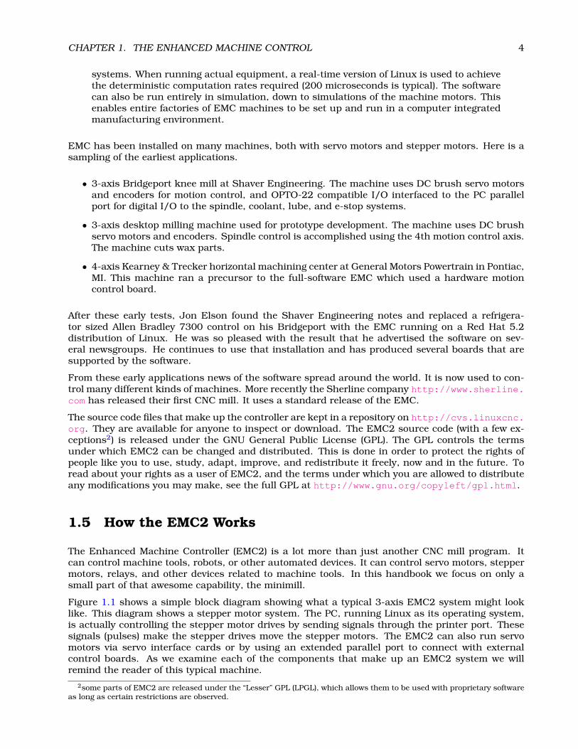
• an OpenGL-based GUI, with an interactive G-Code previewer, called AXIS 1.2
CHAPTER 1. THE ENHANCED MACHINE CONTROL 6
Figure 1.2: The AXIS Graphical Interface
Tkemc and Mini will run on Linux, Mac, and Microsoft Windows if the Tcl/Tk programming languagehas been installed. The Mac and Microsoft Windows version can connect to a real-time EMC2running on a Linux machine via a network connection, allowing the monitoring of the machinefrom a remote location. Instructions for installing and configuring the connection between a Mac orMicrosoft Machine and a PC running the EMC2 can be found in the Integrators Handbook.
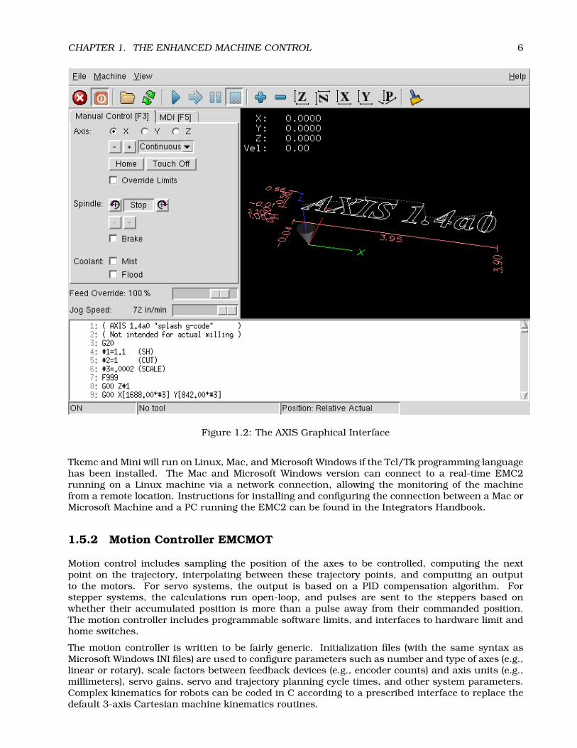
1.5.2 Motion Controller EMCMOT
Motion control includes sampling the position of the axes to be controlled, computing the nextpoint on the trajectory, interpolating between these trajectory points, and computing an outputto the motors. For servo systems, the output is based on a PID compensation algorithm. Forstepper systems, the calculations run open-loop, and pulses are sent to the steppers based onwhether their accumulated position is more than a pulse away from their commanded position.The motion controller includes programmable software limits, and interfaces to hardware limit andhome switches.
The motion controller is written to be fairly generic. Initialization files (with the same syntax asMicrosoft Windows INI files) are used to configure parameters such as number and type of axes (e.g.,linear or rotary), scale factors between feedback devices (e.g., encoder counts) and axis units (e.g.,millimeters), servo gains, servo and trajectory planning cycle times, and other system parameters.Complex kinematics for robots can be coded in C according to a prescribed interface to replace thedefault 3-axis Cartesian machine kinematics routines.

CHAPTER 1. THE ENHANCED MACHINE CONTROL 7
Figure 1.3: The Keystick interface
1.5.3 Discrete I/O Controller EMCIO
Discrete I/O controllers are highly machine-specific, and are not customizable in general usingthe INI file technique used to configure the more generic motion controller. However, since EMC2uses the HAL, reconfiguration of the I/O subsystem has become very powerful and flexible. EMC2contains a Programmable Logic Controller module (behaves just like a hardware PLC) that can beused for very complex scenarios (tool changers, etc.).
In EMC2 there is only one big I/O controller, which provides support for all kinds of actions andhardware control. All its outputs and inputs are HAL pins (more on this later on), so you can useonly the subset that fits your hardware and is necessary for your application.
1.5.4 Task Executor EMCTASK
The Task Executor is responsible for interpreting G and M code programs whose behavior doesnot vary appreciably between machines. G-code programming is designed to work like a machinistmight work. The motion or turns of a handwheel are coded into blocks. If a machinist wanted hismill to move an inch in the +X direction at some feedrate, he might slowly turn the handwheel fiveturns clockwise in 20 seconds. The same machinist programming that same move for CNC mightwrite the following block of code.
G1 F3 X1.000

CHAPTER 1. THE ENHANCED MACHINE CONTROL 8
Figure 1.4: The Mini Graphical Interface
G1 means that the machine is supposed to run at a programmed feedrate rather than at the fastestspeed that it can (G0 is the way to command a rapid move like you would make above the workwhen not cutting). The F3 means that it should travel at 3 inches a minute or 3 millimeters aminute if it is working in metric mode. The X1.000 (assuming that the X axis started at zero) meansthe machine should move one inch in the positive X direction. You will read quite a bit more aboutG-code in the programming chapters .
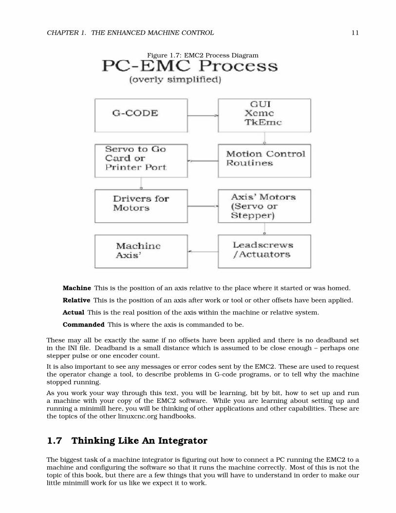
Figure 1.7 is a block diagram of how a personal computer running the EMC2 is used to controla machine with G-code. The actual G-code can be sent using the MDI (Machine Device Interface)mode or it can be sent as a file when the machine is in Auto mode. These choices are made by theoperator and entered using one of the Graphical User Interfaces available with the software.
G-code is sent to the interpreter which compares the new block with what has already been sentto it. The interpreter then figures out what needs to be done for the motion and input or outputsystems and sends blocks of canonical commands to the task and motion planning programs.
1.6 Thinking Like a Machine Operator
This book will not even pretend that it can teach you to run a mill or a lathe. Becoming a machinisttakes time and hard work. An author once said, “We learn from experience, if at all.” Broken tools,gouged vices, and scars are the evidence of lessons taught. Good part finish, close tolerances, and
CHAPTER 1. THE ENHANCED MACHINE CONTROL 9
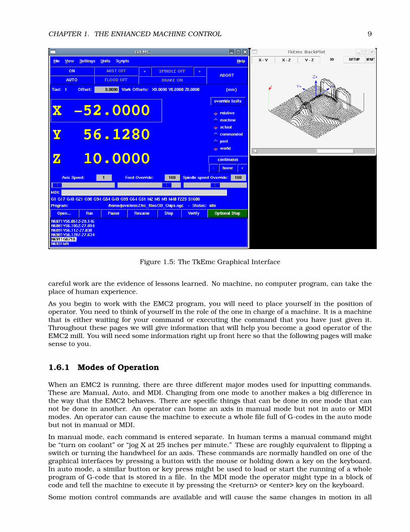
Figure 1.5: The TkEmc Graphical Interface
careful work are the evidence of lessons learned. No machine, no computer program, can take theplace of human experience.
As you begin to work with the EMC2 program, you will need to place yourself in the position ofoperator. You need to think of yourself in the role of the one in charge of a machine. It is a machinethat is either waiting for your command or executing the command that you have just given it.Throughout these pages we will give information that will help you become a good operator of theEMC2 mill. You will need some information right up front here so that the following pages will makesense to you.
1.6.1 Modes of Operation
When an EMC2 is running, there are three different major modes used for inputting commands.These are Manual, Auto, and MDI. Changing from one mode to another makes a big difference inthe way that the EMC2 behaves. There are specific things that can be done in one mode that cannot be done in another. An operator can home an axis in manual mode but not in auto or MDImodes. An operator can cause the machine to execute a whole file full of G-codes in the auto modebut not in manual or MDI.
In manual mode, each command is entered separate. In human terms a manual command mightbe “turn on coolant” or “jog X at 25 inches per minute.” These are roughly equivalent to flipping aswitch or turning the handwheel for an axis. These commands are normally handled on one of thegraphical interfaces by pressing a button with the mouse or holding down a key on the keyboard.In auto mode, a similar button or key press might be used to load or start the running of a wholeprogram of G-code that is stored in a file. In the MDI mode the operator might type in a block ofcode and tell the machine to execute it by pressing the <return> or <enter> key on the keyboard.
Some motion control commands are available and will cause the same changes in motion in all
CHAPTER 1. THE ENHANCED MACHINE CONTROL 10
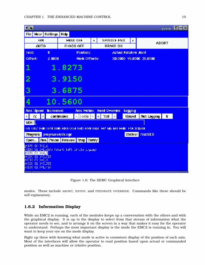
Figure 1.6: The XEMC Graphical Interface
modes. These include ABORT, ESTOP, and FEEDRATE OVERRIDE. Commands like these should beself explanatory.
1.6.2 Information Display
While an EMC2 is running, each of the modules keeps up a conversation with the others and withthe graphical display. It is up to the display to select from that stream of information what theoperator needs to see, and to arrange it on the screen in a way that makes it easy for the operatorto understand. Perhaps the most important display is the mode the EMC2 is running in. You willwant to keep your eye on the mode display.
Right up there with knowing what mode is active is consistent display of the position of each axis.Most of the interfaces will allow the operator to read position based upon actual or commandedposition as well as machine or relative position.
CHAPTER 1. THE ENHANCED MACHINE CONTROL 11
Figure 1.7: EMC2 Process Diagram
Machine This is the position of an axis relative to the place where it started or was homed.
Relative This is the position of an axis after work or tool or other offsets have been applied.
Actual This is the real position of the axis within the machine or relative system.
Commanded This is where the axis is commanded to be.
These may all be exactly the same if no offsets have been applied and there is no deadband setin the INI file. Deadband is a small distance which is assumed to be close enough – perhaps onestepper pulse or one encoder count.
It is also important to see any messages or error codes sent by the EMC2. These are used to requestthe operator change a tool, to describe problems in G-code programs, or to tell why the machinestopped running.
As you work your way through this text, you will be learning, bit by bit, how to set up and runa machine with your copy of the EMC2 software. While you are learning about setting up andrunning a minimill here, you will be thinking of other applications and other capabilities. These arethe topics of the other linuxcnc.org handbooks.
1.7 Thinking Like An Integrator
The biggest task of a machine integrator is figuring out how to connect a PC running the EMC2 to amachine and configuring the software so that it runs the machine correctly. Most of this is not thetopic of this book, but there are a few things that you will have to understand in order to make ourlittle minimill work for us like we expect it to work.

CHAPTER 1. THE ENHANCED MACHINE CONTROL 12
1.7.1 Units
Units can be confusing. You might ask, “Does it work in inches, feet, centimeters, millimeters, orwhat?” There are several possible answers to this question but the best one is that it works in theunits that you set it to work in.
At a machine level, we set each axis’s units to some value using an INI variable that looks like this.
UNITS = 1
or
UNITS = 0.03937007874016
The long number above is the distance represented by one millimeter if we convert it into inches.“So,” you say, “the EMC2 uses millimeters internally.” If we use UNITS = 1 then we have definedour user units as millimeters. If we use UNITS = 0.03937007874016 then we have defined our userunits as inches. Using similar arithmetic we could set our units to most any value we wanted. (Youwill want to use inches or millimeters for your minimill, but some who run vehicles with the EMC2have been known to set units to kilometers or miles.)
After we have decided upon a value for the units for an axis, we tell the EMC2 how may step pulsesor encoder pulses it should send or read for each unit of distance to be traveled. Once we have donethis, the EMC2 knows how to count units of distance. However it is very important to understandthat this counting of distance is different from the commanding of distance. You can commanddistance in millimeters or inches without even thinking about the units that you defined. There areG-codes that allow you to switch easily between metric and imperial.
1.7.2 Some things we may not want to change.
Within the EMC2 code are a few things that are not easily changed. We call these defaults. Thereare connections that have been made between the running components of the EMC2 that we cannot easily change. We’ll see that there are displays and buttons and keyboard keys that are noteasily shifted about. We’ll learn about and get used to these in the chapters ahead.
1.7.3 Some things we will need to change.
The EMC2 is configured with files that are read at startup and used to override the compiled de-faults. No real controller will likely use the compiled defaults, so you will certainly need to edit atleast some of these files to reflect the specifics of your machine.
There are five kinds of configuration files: INI, NML, TBL, VAR and HAL files. These are reflectedin lower case file extensions to a file name. They may be named stepper.tbl or generic.tbl but theydo the same thing when they are read by the EMC2 as it starts up. Many users copy these andname them for the specific machine. A set of these files named Sherlinemill.ini, Sherlinemill.var,Sherlinemill.tbl and Sherlinemill.nml are certainly more descriptive than a bunch of files namedgeneric.
These files each contain specific information for your CNC.
• stepper.ini contains all the machine parameters such as servo gains, scale factors, cycle times,units, etc. and will certainly need to be edited.
• emc.nml contains communication settings for shared memory and network ports you mayneed to override on your system, although it is likely that you can leave these settings alone.

CHAPTER 1. THE ENHANCED MACHINE CONTROL 13
• stepper.tbl contains the tool information such as which pocket contains which tool, and thelength and diameter for each tool.
• rs274ngc.var contains variables specific to the RS-274-NGC dialect of NC code, notably forsetting the persistent numeric variables for the nine work coordinate systems.
We’ll get into some of the details of these files as we begin to hook up and operate our little machine.
In addition to these four files, there is a standard startup file. Back in the early days of the EMCit was common to have to start up several different tasks in different terminal windows in order toget the EMC to run a machine. Each of these tasks had to be supplied a bunch of information inthe form of arguments in order to be certain that the task started the way that we expected it to. Allof this was tedious and has been replaced by one script. It is named simply ’emc’. This executablescript file controls the startup of all of the modules needed to run a standard version of the EMC2.When run, it lets the user choose a certain configuration.

Part II
Installing
14

Chapter 2
Installing the EMC2 software
2.1 Introduction
One of the problems users often complained about EMC was installing the software itself. Theywere forced to get sources, and compile themselves, and try to set up a RT-patched Linux, etc. Thedevelopers of EMC2 chose to go with a standard distribution called Ubuntu1.
Ubuntu has been chosen, because it fits perfectly into the Open Source views of EMC2:
• Ubuntu will always be free of charge, and there is no extra fee for the "enterprise edition", wemake our very best work available to everyone on the same Free terms.
• Ubuntu comes with full professional support on commercial terms from hundreds of compa-nies around the world, if you need those services. Each new version of Ubuntu receives freesecurity updates for 18 months after release, some versions are supported for even longer.
• Ubuntu uses the very best in translations and accessibility infrastructure that the Free Soft-ware community has to offer, to make Ubuntu usable for as many people as possible.
• Ubuntu is released regularly and predictably; a new release is made every six months. Youcan use the current stable release or help improve the current development release.
• The Ubuntu community is entirely committed to the principles of free software development;we encourage people to use open source software, improve it and pass it on.
2.2 EMC Download Page
You will find the most recent releases of EMC2 announced on www.linuxcnc.org. The releasesof EMC2 will be done in two ways (sources and binary package). The sources (described in theDevelopers Handbook) consist of a tarball (emc2-<version>.tar.gz), which you should download andunpack into your home directory.
This document (oriented towards the end-user) will only try to explain how to install the binarypackage on the Ubuntu distribution2.
1“Ubuntu” is an ancient African word, meaning “humanity to others”. Ubuntu also means “I am what I am because ofwho we all are”. The Ubuntu Linux distribution brings the spirit of Ubuntu to the software world. You can read more aboutit at http://www.ubuntu.com
2For information regarding other Linux variants, check the Developers Handbook or ask for help on the emc-developersmailing list http://sourceforge.net/mail/?group_id=6744.
15

CHAPTER 2. INSTALLING THE EMC2 SOFTWARE 16
2.3 EMC2 Live CD
The EMC2 team now has a custom Live-CD based on Ubuntu 6.06 that will let you try out EMC2before installing, and it’s also the easiest way to install Ubuntu and EMC2 together.
Just download the ISO http://linuxcnc.org/iso/emc2-ubuntu6.06-desktop-i386.iso (EUMirror http://dsplabs.utt.ro/~juve/emc/) and burn it to a CD. (The MD5SUM of the CD is6ee5048eb9cb424aa030dfedccc5386b)
When you boot the CD on your machine, you can see and experiment with the exact environmentand EMC2 software that you will have if you choose to install it.
If you like what you see, just click the Install icon on the desktop, answer a few questions (yourname, timezone, password) and the install completes in a few minutes.
This install gives you all the benefits of the community-supported Ubuntu distribution as well asbeing automatically configured for EMC2. As new Ubuntu updates or EMC2 releases are made, theUpdate manager will let you know and allow you to easily upgrade.
2.4 EMC2 install script
We also provide a simple script to install emc2 on Ubuntu for users with an existing installation ofUbuntu. It runs the commands explained in 2.5.
To use it you need to :
• Download the script from http://www.linuxcnc.org/emc2-install.sh (for Ubuntu 5.10)or http://linuxcnc.org/dapper/emc2-install.sh (For Ubuntu 6.06)
• Save it on your Desktop. Right-click the icon, select Properties. Go to the Permissions tab andcheck the box for Owner: Execute. Close the Properties window.
• Now double-click the emc2-install.sh icon, and select "Run in Terminal". A terminal will appearand you will be asked for your password.
• When the installation asks if you are sure you want to install the EMC2 packages, hit Enter toaccept. Now just allow the install to finish.
• When it is done, you must reboot (System > Log Out > Restart the Computer), and when youlog in again you can run EMC2 by selecting it on the Applications > CNC Menu.
• If you aren’t ready to set up a machine configuration, try the sim-AXIS configuration; it runs a"simulated machine" that requires no attached hardware.
• Now that the initial installation is done, Ubuntu will prompt you when updates of EMC2 or itssupporting files are available. When they are, you can update them easily and automaticallywith the Update Manager.
2.5 Manual installing using apt commands.
The following few section will describe how to install EMC2 using a console and apt-commands. Ifyou know a bit about Linux and Debian-flavored distributions this might be trivial. If not, you mightconsider reading 2.4.
First add the repository to /etc/apt/sources.list:
$ sudo sh -c ’echo "deb http://www.linuxcnc.org/emc2/ dapper emc2" >>/etc/apt/sources.list;’$ sudo sh -c ’echo "deb-src http://www.linuxcnc.org/emc2/ dapper emc2" >>/etc/apt/sources.list’

CHAPTER 2. INSTALLING THE EMC2 SOFTWARE 17
Or replace ’dapper’ above with ’breezy’ if you still use Ubuntu 5.10 Breezy Badger.
Then update & get emc2.
$ sudo apt-get update$ sudo apt-get install emc2
This command will install the emc23 package along with all dependencies4.
You might get warnings that the packages are from an untrusted source (this means your com-puter doesn’t recognize the GPG signature on the packages). To correct that issue the followingcommands:
$ gpg --keyserver pgpkeys.mit.edu --recv-key BC92B87F
$ gpg -a --export BC92B87F | sudo apt-key add -
3AXIS is now part of emc2. You don’t need to install emc2-axis as previously.4The dependencies are one of the nicest thing in Debian based distributions. They assure you have everything installed
that you need. In the case of emc2 it’s even a RT-patched kernel, and all needed libraries.

Chapter 3
Compiling EMC2 from source
3.1 Introduction
The third hurdle that you face when you begin to set up the EMC2 is getting and installing the EMC2software itself. All of EMC2 has been placed on cvs.linuxcnc.org in a concurrent versioning (CVS)repository. EMC2 is also available as a precompiled package (for various platforms) for downloadfrom that site.
Installation can be a daunting task to people new to Linux. The hardest part is getting the Real TimeLinux patch up and running. After that, installing EMC is pretty easy. With that said, we recentlyprovided a completely new experience for users, they only need to install Ubuntu (a very friendlylinux distribution), then run a single install script, and they already should have the Real Time partand EMC2 working. Information how to access this can be found on the www.linuxcnc.org pageunder Download.
3.2 EMC Download Page
You will find the most recent releases of EMC2 announced on www.linuxcnc.org. The releases ofEMC2 will be done in two ways (sources and binary package). The sources (described furtheron)consist of a tarball (emc2-version.tar.gz), which you should download and unpack into your homedirectory.
3.3 EMC2 Release Description
EMC2 will be using a release model similar to (but simpler than) the one used by Debian. At anyone time there will be three versions of EMC2. Debian uses "stable", "testing", and "unstable". Wewill be using "Released", "Testing", and "Head". For the latest information, click on the version youare interested in.
Released is exactly that, a released version of EMC2 with a version number. It is tested by bothdevelopers and beta users before being released, and is suitable for the average user. Most de-velopers and IRC/mailing list regulars are able to help support people running a released version."Released" is available in several forms, including .debs for Ubuntu and source tarballs for localcompilation. There will be a debian repository which will always have the latest released version(and thus allows for easy upgrades from one stable release to the next).
Testing is a version of EMC2 that is ready for "beta testing" but not for general release. Beforea version is labeled testing it will be known to compile and run on several different platforms,
18

CHAPTER 3. COMPILING EMC2 FROM SOURCE 19
but there will probably be various limitations and known problems. The Testing wiki page willattempt to list known problems and workarounds, but there will probably also be undiscoveredbugs. Since Testing is "beta" software, it should not be used for anything critical. Users of Testingneed to understand that it is beta software, and must be willing to give detailed bug reports if thingsgo wrong. Testing is available primarily as a tag in CVS, although for convenience of testers, a"testing" debian repository and/or tarballs may also be available. The EMC Board of Directors willdecide when "Testing" is worthy of becoming "Released". This is a formal decision, made by motionand voting on the board mailing list or board IRC channel.
TRUNK is a CVS term for where all the primary development takes place. TRUNK can be brokenat any time. When TRUNK reaches a state that is deemed worthy of testing by a larger number ofpeople, the "Testing" tag will be moved. This is an informal decision, made by concensus of leaddevelopers, usually on IRC. Development will immediately continue, and TRUNK will once againdiverge from Testing. TRUNK has no "version number", and on a busy weekend it can literallychange every 10 minutes.
3.4 Download and source preparation.
The following few section will describe how to get EMC2, and compile it.
To download, simply go to www.linuxcnc.org to the Download page, and get the latest release ortesting tarball.
Once you have it, extract it to your home folder:
$ cd ~/$ tar xzvf emc2-version.tar.gz
Next you’ll need to decide what kind of install you want. There are two ways to try EMC2 out:
Installed Like most other software on Linux, the files are placed in system directories, and isautomatically available to all users of that computer.1
Run-in-place All the files for EMC2 are kept inside the emc2 directory. This is useful for trying outEMC2, especially when there is another version of EMC2 already installed on the system.
3.4.1 Downloading the CVS version
If you wish to use the TRUNK version of emc2, please follow the instructions on our wiki to obtainthe source code: http://wiki.linuxcnc.org/cgi-bin/emcinfo.pl?CVS
3.5 Installed
EMC2 followes the standard way of compiling linux software. To compile it simply go to the sourcesfolder:
$ cd ~/emc2/src
and issue these commands:
$ ./configure$ make && sudo make install
To run it simply type ’emc’.1The pre-built packages for Ubuntu Linux use the “installed” method

CHAPTER 3. COMPILING EMC2 FROM SOURCE 20
3.6 Run-in-place
If you want only to test the software before installing it, or if you’re worried about overwriting anexisting installation, there is a Run-In-Place (RIP) mode which you can try out. In this mode, thereis no installation step, and no files are placed outside the top directory , ~/emc2 in this example.
$ cd ~/emc2/src
and issue these commands:
$ ./configure --enable-run-in-place$ make && sudo make setuid
In a shell session where you want to use the run-in-place version of emc2, execute
$ . ~/emc2/scripts/emc-environment
Until you close that terminal, it will be set up so that the programs and manual pages from theRun-In-Place directory are available without referring to the path each time. After that you can runEMC2 by issuing:
$ emc
3.7 Simulator
To install EMC2 on a system without a realtime kernel, add --enable-simulator to the configurecommandline. In this mode, EMC2 runs as a purely userspace program. No hardware can becontrolled and realtime scheduling is not guaranteed, but the other features of HAL, EMC andits various user interfaces are available. When using --enable-run-in-place, the sudo makesetuid step is unneeded.
3.8 Editing and Recompiling
You may need to recompile the EMC2 code for a number of reasons. You may have modified thesource code, or you may have downloaded just a few new files. To recompile, do the following:
$ cd ~/emc2/src$ make && sudo make install # for run-installed$ make && sudo make setuid # for run-in-place$ make # for run-in-place, simulator
The build process is smart enough to only rebuild things that are affected by your changes.
2By putting this command in a shell start-up script, such as ~/.bash_profile, you do not need to manually run it ineach terminal window.
Part III
EMC Configuration
21

Chapter 4
INI Configuration
4.1 Files Used for Configuration
The EMC is configured with human readable text files. All of these files can be read and edited inany of the common text file editors available with most any Linux distribution.1 You’ll need to be abit careful when you edit these files. Some mistakes will cause the startup to fail. These files areread whenever the software starts up. Some of them are read repeatedly while the CNC is running.
Configuration files include;
INI The ini file overrides defaults that are compiled into the EMC code. It also provides sectionsthat are read directly by the Hardware Abstraction Layer.
HAL The hal files start up process modules and provide linkages between EMC signals and specifichardware pins.
VAR The var file provide a set of numbered variables for use by the interpreter. These values aresaved from one run to another.
TBL The tbl file saves tool information.
NML The nml file configures the communication channels used by the EMC. It is normally setupto run all of the communication within a single computer but can be modified to communicatebetween several computers.
.emcrc This file saves user specific information and is created to save the name of the directorywhen the user first selects an EMC configuration.2
This chapter describes the EMC2’s INI file in just enough detail so that the reader can understandwhich variable values might need to be edited in order to make a stock configuration conform to areal machine.3
4.2 The INI File Layout
A typical INI file follows a rather simple layout that includes;
1Don’t confuse a text editor with a word processor. A text editor like gedit or kwrite produce files that are plain text.They also produce lines of text that are separated from each other. A word processor like Open Office produce files withparagraphs and word wrapping and lots of embedded codes that control font size and such. A text editor does none of this.
2Usually this file is in the users home directory (e.g. /home/user/ )3Complete reference to these files are left to the Integrator and Developer Handbooks.
22
CHAPTER 4. INI CONFIGURATION 23
• comments.
• sections,
• variables.
Each of these elements is separated on single lines. Each end of line or newline character creates anew element.
4.2.1 Comments
A comment line is started with a ; or a # mark. When the ini reader sees either of these marks atthe start a line, the rest of the line is ignored by the software. Comments can be used to describewhat some INI element will do.
; This is my little mill configuration file.; I set it up on January 12, 2006
Comments can also be used to select between several values of a single variable.
# DISPLAY = tkemcDISPLAY = axis# DISPLAY = mini# DISPLAY = keystick
In this list, the DISPLAY variable will be set to axis because all of the others are commented out.If someone carelessly edits a list like this and leaves two of the lines uncommented, the first oneencountered will be used.
4.2.2 Sections
Sections in an INI file work like file folders in a drawer. They separate variables based on whatpart of the EMC they refer to. A section line looks like [THIS_SECTION]. The name of the section isenclosed in brackets. Common INI files have several sections including;
• [EMC] general information (4.3.1)
• [DISPLAY] selects and sets up some display characteristics (4.3.2
• [TASK] sets up the task planner (4.3.4)
• [RS274NGC] location of interpreter specific file
• [EMCMOT] motion module and default characteristics (4.3.3)
• [HAL] hardware configuration files and commands (4.3.5)
• [TRAJ] information for the motion planner (4.3.6)
• [AXIS_0] ... [AXIS_n] individual axis variables (4.3.7)
• [EMCIO] emc’s input and output variables. (4.3.8)
Each of these section names are on a line by themselves so you can quickly scan through the file.
CHAPTER 4. INI CONFIGURATION 24
4.2.3 Variables
A variable line is made up of a variable name, an equals sign(=), and a value. Everything from thefirst non-whitespace character after the = up to the end of the line is passed as the value, so you canembed spaces in string symbols if you want to or need to. A variable name is often called a keyword.These variables and the values they are assigned are the way that the INI affects the operation ofthe EMC. You can edit the values for each keyword in any text editor. Changes don’t take effectuntil the next time the controller is run.
The following sections detail each section of the configuration file, using sample values for theconfiguration lines.
Some of the variables are used by EMC, and must always use the section names and variable namesshown. Other variables are used only by HAL, and the section names and variable names shownare those used in the sample configuration files.
4.3 INI Variable Definitions
4.3.1 [EMC] Section
VERSION = $Revision: 1.3 $ The version number for the INI file. The value shown here looks oddbecause it is automatically updated when using the Revision Control System. It’s a good ideato change this number each time you revise your file. If you want to edit this manually justchange the number and leave the other tags alone.
MACHINE = My Controller This is the name of the controller, which is printed out at the top ofmost graphical interfaces. You can put whatever you want here as long as you make it a singleline long.
RS274NGC_STARTUP_CODE = G21 G90 A string of NC codes that the interpreter is initializedwith. These are the codes that an interpreter will be reset to.
4.3.2 [DISPLAY] Section
DISPLAY = tkemc The name of the user interface to use. Valid options may include:
• axis
• keystick
• mini
• tkemc
• xemc
4.3.3 [EMCMOT] Section
BASE_PERIOD = 50000 Base task period, in nanoseconds - this is the fastest thread in the ma-chine. It’s units are nanoseconds. This is a fairly conservative value but if you are installingon a very old, slow processor you may have to make this a larger number or the machine maylock up or reboot.You might want to make this value smaller if you have a fast computer because this value setsthe maximum number of stepper pulses you can get from your machine. It has little effect
CHAPTER 4. INI CONFIGURATION 25
on servo systems so leave it large. In the absence of long setup or hold times, the absolutemaximum step rate for a step+direction motor is one step per two BASE_PERIOD, so
max_step_rate [ stepssecond ] =
109
2 ∗ base_period
Thus, the BASE_PERIOD shown above gives an absolute maximum step rate of 10000 stepsper second.
SERVO_PERIOD = 1000000 Servo task period is also in nanoseconds. This value will be roundedto an integer multiple of BASE_PERIOD.Most systems will not need to change this value. It is the update rate of the low level motionplanner. You’ll need it even if you only have steppers.
TRAJ_PERIOD = 10000000 Trajectory Planner task period in nanoseconds This value will be roundedto an integer multiple of SERVO_PERIOD.Folk with fast computers have found that reducing this value by half will give them smothermotion blending during contour cutting .
4.3.4 [TASK] Section
The [TASK] section contains general parameters for EMCTASK, which includes primarily the NClanguage interpreter and the sequencing logic for sending commands to EMCMOT and EMCIO.
CYCLE_TIME = 0.100 The period, in seconds, at which EMCTASK will run. This parameter mostlyaffects the polling interval when waiting for motion to complete, or when executing a pauseinstruction. It no longer affects the throughput when transferring segments to the real-timelayer. Making it 0.0 or a negative number will tell EMCTASK not to sleep at all.
4.3.5 [HAL] section
The [HAL] section lists files and commands to setup the Hardware Abstraction Layer. If this is astepper system you might see several files here. The exact set would depend upon the configurationof signals at the parallel port. At a minimum you would see the following. Sherline mills use the“standard_pinout”, and “xylotex_pinout” matches the setup for those brand of cards.
HALFILE = core_stepper.halHALFILE = standard_pinout.hal# HALFILE = xylotex_pinout.hal
You can also add variables (commands really) here.4
4.3.6 [TRAJ] Section
The [TRAJ] section contains general parameters for the trajectory planning module in EMCMOT.You will not need to change these if you are applying EMC to a common three axis mill in the UnitedStates of America. If you are in an area using metric hardware components you might be workingwith the stepper_mm.ini where these numbers are already setup for that system of units.
AXES = 3 The number of controlled axes in the system. If you have a four axis system put thatnumber here and edit the next two variables as well
4See the Integrator Handbook for details.
CHAPTER 4. INI CONFIGURATION 26
COORDINATES = X Y Z The names of the axes being controlled. X, Y, Z, A, B, and C are all valid.It is also possible to have X Y Y Z and control ganged slides. For a fourth axis mounted on Xyou would use X Y Z A. This has no effect on the mapping from G-code axis names (X- Y- Z-)to joint numbers–kinematics does this–but is largely for documentation.
HOME = 0 0 0 Coordinates of the homed position of each axis. Again for a fourth axis you will need0 0 0 0. This value is only used for machines with nontrivial kinematics. On machines withtrivial kinematics this value is ignored.
LINEAR_UNITS = <units> The name of units to be used. Possible choices are (in, inch, imperial,metric, mm). For systems executing in native English (inch) units, this value shall be any oneof ’in’, ’inch’ or ’imperial’. For systems executing in native millimeter units, this value shall be’mm’ or ’metric’. This does not affect the ability to program in English or metric units in NCcode. It is used to determine how to interpret the numbers reported in the controller status byexternal programs.
ANGULAR_UNITS = <units> The name of units to be used. For systems executing in native degreeunits, this value should be ’deg’ or ’degree’. For systems executing in radians, this value is’rad’ or ’radian’. Another possible value is ’grad’ or ’gon’ for units operating in gradians (400gradians in a full circle).
DEFAULT_VELOCITY = 0.0167 The initial velocity used for axis or coordinated axis motion, inuser units per second. The value shown is one unit per minute.
DEFAULT_ACCELERATION = 2.0 The initial acceleration used for axis or coordinated axis motion,in user units per second per second.
MAX_VELOCITY = 5.0 The maximum velocity for any axis or coordinated move, in user units persecond. Think for a moment what this value really means in hardware terms. The formula isMAX_VELOCITY * 60. In this case this is 300 inches per minute.
MAX_ACCELERATION = 20.0 The maximum acceleration for any axis or coordinated axis move,in user units per second per second.
POSITION_FILE = position.txt If set to a non-empty value, the joint positions are stored betweenruns in this file. This allows the machine to start with the same coordinates it had on shut-down.5 If unset, joint positions are not stored and will begin at 0 each time emc is started.
4.3.7 [AXIS_<num>] Section
The [AXIS_0], [AXIS_1], etc. sections contains general parameters for the individual componentsin the axis control module. The axis section names begin numbering at 0, and run through thenumber of axes specified in the [TRAJ] AXES entry minus 1.
Values for the various parameters of LINEAR axes are in the units specified in the [TRAJ] LIN-EAR_UNITS entry. Values for the position of ANGULAR axes are in the units specified in the [TRAJ]ANGULAR_UNITS entry.
TYPE = LINEAR The type of axes, either LINEAR or ANGULAR.
MAX_VELOCITY = 1.2 Per axis maximum velocity while coordinated motion is in effect.
MAX_ACCELERATION = 20.0 Per axis maximum acceleration while coordinated motion is in effect.
BACKLASH = 0.000 Backlash compensation value can be used to make up for small deficienciesin the hardware used to drive an axis. Don’t expect this to compensate for poor mechanicalelements. The value set here is in UNITS.
5This assumes there was no movement of the machine while powered off. It helps on smaller machines without homeswitches.
CHAPTER 4. INI CONFIGURATION 27
COMP_FILE = file.extension A file holding a compensation structure for the specific axis. Thevalues inside are triplets of nominal, forward and reverse positions which correspond to thenominal position (where it should be), forward (where the axis is while travelling forward) andreverse (where the axis is while travelling back). One set of triplets per line. Currently the limitinside EMC2 is for 256 triplets / axis.
COMP_FILE_TYPE = 1 Specifying a non-zero value changes the expected format of the COMP_FILE.While type == 0, the expected values are triplets for nominal, forward & reverse. With COMP_FILE_TYPEnon-zero, the expected values in the COMP_FILE are nominal, forward_trim and reverse_trim.These correspond to the nominal, nominal-forward and nominal-reverse defined above.
INPUT_SCALE = 4000 This variable has slightly different meaning for stepper and for servo sys-tems. For steppers, the only number it is the number of pulses required to move the axis oneUNIT.For servos this value is the scale factors for the axis input from the raw feedback device, e.g.,an incremental encoder. The units on the scale value are in raw units (e.g., counts) per userunits (e.g., inch).The value for scale can be obtained by doing a unit analysis, i.e., units are
sensor units
desired input SI units
For example, on a 2000 counts per rev encoder, and 10 revs/inch gearing, and desired unitsof mm, we have
[scaleunits] = 2000counts
rev∗ 10
rev
inch∗ 1/25.4
inch
mm
= 787.4counts
mm
and, as a result,input[mm] = (encoder[counts])/787.4
MIN_LIMIT = -1000 The minimum limit (soft limit) for axis motion, in user units. When this limitis exceeded, the controller aborts axis motion.
MAX_LIMIT = 1000 The maximum limit (soft limit) for axis motion, in user units. When this limitis exceeded, the controller aborts axis motion.
MIN_FERROR = 0.010 This is the value by which the axis is permitted to deviate from commandedposition at very low speeds. If MIN_FERROR is smaller than FERROR, the two produce a rampof error trip points. You could think of this as a graph where one dimension is speed andthe other is permitted following error. As speed increases the amount of following error alsoincreases toward the FERROR value.
FERROR = 1.0 FERROR is the maximum allowable following error, in user units. If the differencebetween commanded and sensed position exceeds this amount, the controller disables servocalculations, sets all the outputs to 0.0, and disables the amplifiers. If MIN_FERROR is presentin the .ini file, velocity-proportional following errors are used. Here, the maximum allowablefollowing error is proportional to the speed, with FERROR applying to the rapid rate set by[TRAJ]MAX_VELOCITY, and proportionally smaller following errors for slower speeds. Themaximum allowable following error will always be greater than MIN_FERROR. This preventssmall following errors for stationary axes from inadvertently aborting motion. Small followingerrors will always be present due to limited position resolution, vibration, etc.
UNITS = inch Historically, the UNITS were specified for each axis. It is now preferable to specify the[TRAJ]LINEAR_UNITS and [TRAJ]ANGULAR_UNITS values only, and have no [AXIS_n]UNITSsetting.
CHAPTER 4. INI CONFIGURATION 28
4.3.7.1 Homing-related items
The next few parameters are Homing related, for a better explanation read Section 4.4
HOME_OFFSET = 0.0 The axis position of the home switch or index pulse.
HOME_SEARCH_VEL = 0.0 A value of zero means assume that the current location is the homeposition for the machine. If your machine has no home switches you will want to leave thisvalue alone.
HOME_LATCH_VEL = 0.0 This is the final velocity to be used during a home sequence.
HOME_USE_INDEX = NO If the encoder used for this axis has an index pulse, and the motion cardhas provision for this signal you may set it to yes. When it is yes, it will affect the kind of homepattern used.
HOME_IGNORE_LIMITS = NO Some machines use a limit switch as a home switch. This variableshould be set to yes if you machine does this.
4.3.7.2 Servo-related items
The following items are for servo-based systems and servo-like systems including the univstep boardfrom Pico Systems. 6
P = 50 The proportional gain for the axis servo. This value multiplies the error between commandedand actual position in user units, resulting in a contribution to the computed voltage for themotor amplifier. The units on the P gain are volts per user unit.
I = 0 The integral gain for the axis servo. The value multiplies the cumulative error between com-manded and actual position in user units, resulting in a contribution to the computed voltagefor the motor amplifier. The units on the I gain are volts per user unit-seconds.
D = 0 The derivative gain for the axis servo. The value multiplies the difference between the currentand previous errors, resulting in a contribution to the computed voltage for the motor amplifier.The units on the D gain are volts per user unit per second.
FF0 = 0 The 0-th order feedforward gain. This number is multiplied by the commanded position,resulting in a contribution to the computed voltage for the motor amplifier. The units on theFF0 gain are volts per user unit.
FF1 = 0 The 1st order feedforward gain. This number is multiplied by the change in commandedposition per second, resulting in a contribution to the computed voltage for the motor amplifier.The units on the FF1 gain are volts per user unit per second.
FF2 = 0 The 2nd order feedforward gain. This number is multiplied by the change in commandedposition per second per second, resulting in a contribution to the computed voltage for themotor amplifier. The units on the FF1 gain are volts per user unit per second per second.
OUTPUT_SCALE = 1.000
OUTPUT_OFFSET = 0.000 These two values are the scale and offset factors for the axis output tothe motor amplifiers. The second value (offset) is subtracted from the computed output (involts), and divided by the first value (scale factor), before being written to the D/A converters.The units on the scale value are in true volts per DAC output volts. The units on the offsetvalue are in volts. These can be used to linearize a DAC.
6Refer to the the EMC2_Integrator_Manual for further information about servo systems and PID control.
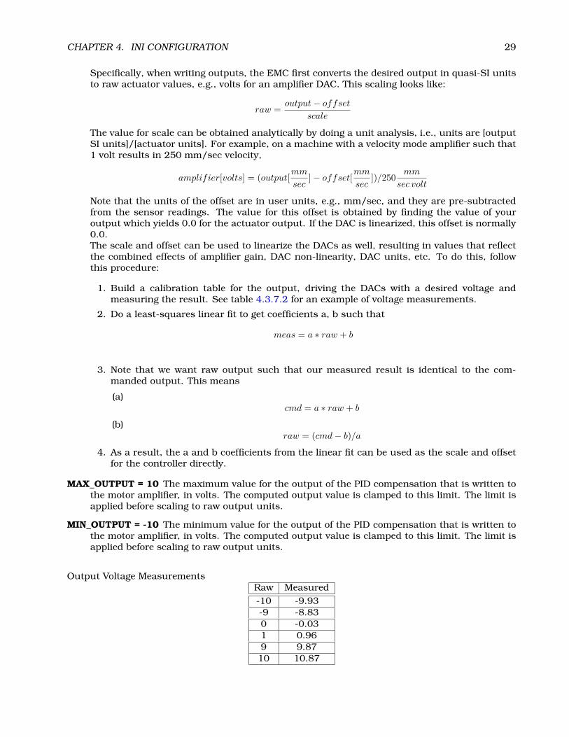
CHAPTER 4. INI CONFIGURATION 29
Specifically, when writing outputs, the EMC first converts the desired output in quasi-SI unitsto raw actuator values, e.g., volts for an amplifier DAC. This scaling looks like:
raw =output− offset
scale
The value for scale can be obtained analytically by doing a unit analysis, i.e., units are [outputSI units]/[actuator units]. For example, on a machine with a velocity mode amplifier such that1 volt results in 250 mm/sec velocity,
amplifier[volts] = (output[mm
sec]− offset[
mm
sec])/250
mm
sec volt
Note that the units of the offset are in user units, e.g., mm/sec, and they are pre-subtractedfrom the sensor readings. The value for this offset is obtained by finding the value of youroutput which yields 0.0 for the actuator output. If the DAC is linearized, this offset is normally0.0.The scale and offset can be used to linearize the DACs as well, resulting in values that reflectthe combined effects of amplifier gain, DAC non-linearity, DAC units, etc. To do this, followthis procedure:
1. Build a calibration table for the output, driving the DACs with a desired voltage andmeasuring the result. See table 4.3.7.2 for an example of voltage measurements.
2. Do a least-squares linear fit to get coefficients a, b such that
meas = a ∗ raw + b
3. Note that we want raw output such that our measured result is identical to the com-manded output. This means
(a)cmd = a ∗ raw + b
(b)raw = (cmd− b)/a
4. As a result, the a and b coefficients from the linear fit can be used as the scale and offsetfor the controller directly.
MAX_OUTPUT = 10 The maximum value for the output of the PID compensation that is written tothe motor amplifier, in volts. The computed output value is clamped to this limit. The limit isapplied before scaling to raw output units.
MIN_OUTPUT = -10 The minimum value for the output of the PID compensation that is written tothe motor amplifier, in volts. The computed output value is clamped to this limit. The limit isapplied before scaling to raw output units.
Output Voltage MeasurementsRaw Measured-10 -9.93-9 -8.830 -0.031 0.969 9.8710 10.87

CHAPTER 4. INI CONFIGURATION 30
4.3.7.3 Stepper-related items
The following items are used by core_stepper.hal to set limits on the step waveforms that will begenerated. They typically include a headroom of 5% to 10% compared to the MAX_VELOCITY andMAX_ACCEL items in the same AXIS.
STEPGEN_MAXVEL = 1.4 A value applied to the stepper pulse generator to provide some overheadfor following error catch up.7
STEPGEN_MAXACCEL = 21.0 Overhead for the stepper pulse generator when it needs to catch up.
4.3.8 [EMCIO] Section
CYCLE_TIME = 0.100 The period, in seconds, at which EMCIO will run. You can make this assmall as you want to increase the throughput. Making it 0.0 or a negative number will tellEMCIO not to sleep at all. Ultimately the system loading will limit the effective throughput.
TOOL_TABLE = tool.tbl The file which contains tool information, described in ??
TOOL_CHANGE_POSITION = 0 0 2 Specifies the XYZ location to move to when performing a toolchange.
7The step generator module, stepgen, applies its own limits to acceleration and velocity. We have discovered that it needsto have a little "headroom" over the accel by the trajectory planner, otherwise it can fall slightly behind during accel and laterovershoot as it catches up. In the long term we hope to come up with a clean fix for this problem. In the meantime, pleaseset STEPGEN_MAXVEL to a few percent higher than MAX_VELOCITY, the regular velocity limit and STEPGEN_MAXACCELslightly larger that of MAX_ACCELERATION.
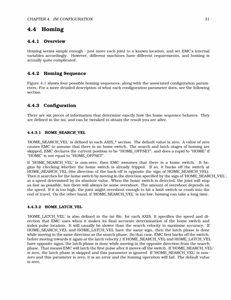
CHAPTER 4. INI CONFIGURATION 31
4.4 Homing
4.4.1 Overview
Homing seems simple enough - just move each joint to a known location, and set EMC’s internalvariables accordingly. However, different machines have different requirements, and homing isactually quite complicated.
4.4.2 Homing Sequence
Figure 4.1 shows four possible homing sequences, along with the associated configuration param-eters. For a more detailed description of what each configuration parameter does, see the followingsection.
4.4.3 Configuration
There are six pieces of information that determine exactly how the home sequence behaves. Theyare defined in the ini, and can be tweaked to obtain the result you are after.
4.4.3.1 HOME_SEARCH_VEL
’HOME_SEARCH_VEL’ is defined in each AXIS_* section. The default value is zero. A value of zerocauses EMC to assume that there is no home switch. The search and latch stages of homing areskipped, EMC declares the current position to be “HOME_OFFSET”, and does a rapid to “HOME” if“HOME” is not equal to “HOME_OFFSET”.
If ’HOME_SEARCH_VEL’ is non-zero, then EMC assumes that there is a home switch. It be-gins by checking whether the home switch is already tripped. If so, it backs off the switch atHOME_SEARCH_VEL (the direction of the back-off is opposite the sign of HOME_SEARCH_VEL).Then it searches for the home switch by moving in the direction specified by the sign of ’HOME_SEARCH_VEL’,at a speed determined by its absolute value. When the home switch is detected, the joint will stopas fast as possible, but there will always be some overshoot. The amount of overshoot depends onthe speed. If it is too high, the joint might overshoot enough to hit a limit switch or crash into theend of travel. On the other hand, if ’HOME_SEARCH_VEL’ is too low, homing can take a long time.
4.4.3.2 HOME_LATCH_VEL
’HOME_LATCH_VEL’ is also defined in the ini file, for each AXIS. It specifies the speed and di-rection that EMC uses when it makes its final accurate determination of the home switch andindex pulse location. It will usually be slower than the search velocity to maximise accuracy. IfHOME_SEARCH_VEL and HOME_LATCH_VEL have the same sign, then the latch phase is donewhile moving in the same direction as the search phase. (In that case, EMC first backs off the switch,before moving towards it again at the latch velocity.) If HOME_SEARCH_VEL and HOME_LATCH_VELhave opposite signs, the latch phase is done while moving in the opposite direction from the searchphase. That means EMC will latch the first pulse after it moves off the switch. If ’HOME_SEARCH_VEL’is zero, the latch phase is skipped and this parameter is ignored. If ’HOME_SEARCH_VEL’ is non-zero and this parameter is zero, it is an error and the homing operation will fail. The default valueis zero.
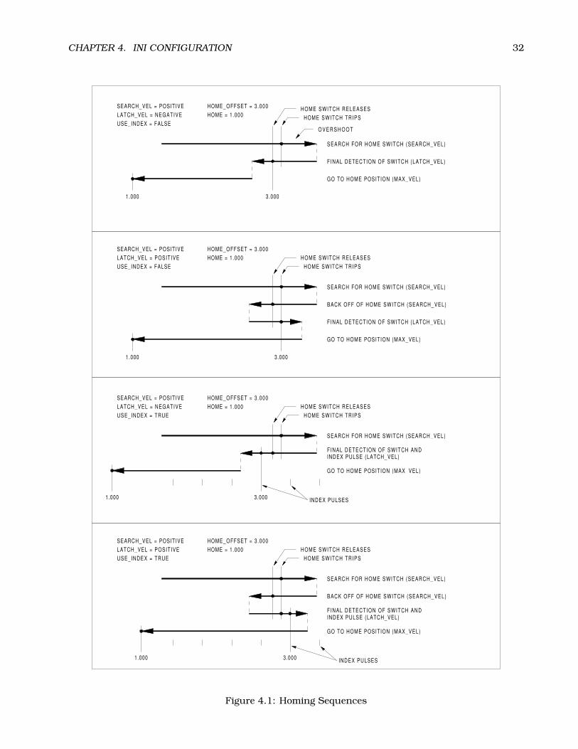
CHAPTER 4. INI CONFIGURATION 32
INDEX PULSES
INDEX PULSES
HOME SWITCH TRIPS
HOME SWITCH TRIPS
HOME SWITCH TRIPS
HOME SWITCH TRIPS
SEARCH FOR HOME SWITCH (SEARCH_VEL)
SEARCH FOR HOME SWITCH (SEARCH_VEL)
SEARCH FOR HOME SWITCH (SEARCH_VEL)
SEARCH FOR HOME SWITCH (SEARCH_VEL)
BACK OFF OF HOME SWITCH (SEARCH_VEL)
BACK OFF OF HOME SWITCH (SEARCH_VEL)
F INAL DETECTION OF SWITCH (LATCH_VEL)
F INAL DETECTION OF SWITCH ANDINDEX PULSE (LATCH_VEL)
F INAL DETECTION OF SWITCH (LATCH_VEL)
F INAL DETECTION OF SWITCH ANDINDEX PULSE (LATCH_VEL)
GO TO HOME POSITION (MAX_VEL)
GO TO HOME POSITION (MAX_VEL)
GO TO HOME POSITION (MAX_VEL)
GO TO HOME POSITION (MAX_VEL)
1.000
1.000
1.000
1.000
3.000
3.000
3.000
3.000
SEARCH_VEL = POSITIVE
SEARCH_VEL = POSITIVE
SEARCH_VEL = POSITIVE
SEARCH_VEL = POSITIVE
LATCH_VEL = NEGATIVE
LATCH_VEL = NEGATIVE
LATCH_VEL = POSITIVE
LATCH_VEL = POSITIVE
USE_INDEX = FALSE
USE_INDEX = TRUE
USE_INDEX = FALSE
USE_INDEX = TRUE
HOME_OFFSET = 3 .000
HOME_OFFSET = 3 .000
HOME_OFFSET = 3 .000
HOME_OFFSET = 3 .000
HOME = 1.000
HOME = 1.000
HOME = 1.000
HOME = 1.000
O V E R S H O O T
HOME SWITCH RELEASES
HOME SWITCH RELEASES
HOME SWITCH RELEASES
HOME SWITCH RELEASES
Figure 4.1: Homing Sequences
CHAPTER 4. INI CONFIGURATION 33
4.4.3.3 HOME_IGNORE_LIMITS
’HOME_IGNORE_LIMITS’ is another settable option in the AXIS_* section. It’s a boolean flag, andcan hold the values YES / NO. This flag determines whether EMC will ignore the limit switch inputs.Some machine configurations do not use a separate home switch, instead they route one of the limitswitch signals to the home switch input as well. In this case, EMC needs to ignore that limit duringhoming. The default value for this parameter is NO.
4.4.3.4 HOME_USE_INDEX
’HOME_USE_INDEX’ is a single bit settable in the AXIS_* section. It specifies whether or not thereis an index pulse. If the flag is true (HOME_USE_INDEX = YES), EMC will latch on the rising edgeof the index pulse. If false, EMC will latch on either the rising or falling edge of the home switch(depending on the signs of search_vel and latch_vel). If ’HOME_SEARCH_VEL’ is zero, the latchphase is skipped and this parameter is ignored. The default value is NO.
4.4.3.5 HOME_OFFSET
’HOME_OFFSET’ is a value setable from the ini in the AXIS_* section. It contains the location of thehome switch or index pulse, in joint coordinates. It can also be treated as the distance between thepoint where the switch or index pulse is latched and the zero point of the joint. After detecting theindex pulse, EMC sets the joint coordinate of the current point to “HOME_OFFSET”. The defaultvalue is zero.
4.4.3.6 HOME
’HOME’ is a value setable from the ini in the AXIS_* section. It is the position that the joint willgo to upon completion of the homing sequence. After detecting the index pulse, and setting thecoordinate of that point to “HOME_OFFSET”, EMC makes a move to "HOME" as the final stepof the homing process. The default value is zero. Note that even if this parameter is the sameas “HOME_OFFSET”, the axis will slightly overshoot the latched position as it stops. Thereforethere will always be a small move at this time (unless HOME_SEARCH_VEL is zero, and the entiresearch/latch stage was skipped). This final move will be made at the joint’s maximum velocity.Since the axis is now homed, there should be no risk of crashing the machine, and a rapid move isthe quickest way to finish the homing sequence. 8
4.4.3.7 HOME_IS_SHARED
’HOME_IS_SHARED’ is a value setable from the ini in the AXIS_* section. If there is not a separatehome switch input for this axis, but a number of momentary switches wired to the same pin, setthis value to 1 to prevent homing from starting if one of the shared switches is already closed. Setthis value to 0 to permit homing even if the switch is already closed.
4.4.3.8 HOME_SEQUENCE
’HOME_SEQUENCE’ is a value setable from the ini in the AXIS_* section. This value is used toperform a multi-axis homing sequence (“HOME ALL”) and enforce homing order (e.g., Z may not behomed if X is not yet homed). An axis may be homed after all axes with a lower HOME_SEQUENCEhave already been homed and are at the HOME_OFFSET. If two axes have the same HOME_SEQUENCE,they may be homed at the same time. If HOME_SEQUENCE is -1 or not specified then this joint
8The distinction between ’home’ and ’home_offset’ is not as clear as I would like. I intend to make a small drawing andexample to help clarify it.

CHAPTER 4. INI CONFIGURATION 34
will not be homed by the HOME ALL sequence. HOME_SEQUENCE numbers start with 0 and theremay be no unused numbers.

Chapter 5
EMC2 and HAL
5.1 motion (realtime)
These pins, parameters, and functions are created by the realtime motmod module.
5.1.1 Pins
motion.adaptive-feed IN float When adaptive feed is enabled with M52 P1 (See section ??), thecommanded velocity is multiplied by this value. This effect is multiplicative with the NML-levelfeed override value
motion.digital-out-NN OUT bit These pins are controlled by the M62 through M65 words.
motion.enable IN bit If this bit is driven FALSE, motion stops, the machine is placed in the “ma-chine off” state, and a message is displayed for the operator. For normal motion, drive this bitTRUE.
motion.feed-hold IN bit If this bit is set to TRUE, the feed rate is set to 0.
motion.motion-inpos OUT bit TRUE if the machine is in position.
motion.probe-input IN bit G38.2 uses the value on this pin to determine when the probe hasmade contact. TRUE for probe contact closed (touching), FALSE for probe contact open.
motion.spindle-brake OUT bit TRUE when the spindle brake should be applied
motion.spindle-forward OUT bit TRUE when the spindle should rotate forward
motion.spindle-reverse OUT bit TRUE when the spindle should rotate backward
motion.spindle-on OUT bit TRUE when spindle should rotate
motion.spindle-speed-out OUT float Desired spindle speed in rotations per minute
motion.spindle-index-enable I/O bit For correct operation of spindle synchronized moves, thissignal must be hooked to the index-enable pin of the spindle encoder.
motion.spindle-revs IN float For correct operation of spindle synchronized moves, this signal mustbe hooked to the position pin of the spindle encoder.
35

CHAPTER 5. EMC2 AND HAL 36
5.1.2 Parameters
Many of these parameters serve as debugging aids, and are subject to change or removal at anytime.
motion.coord-error TRUE when motion has encountered an error, such as exceeding a soft limit
motion.coord-mode TRUE when motion is in “coordinated mode”, as opposed to “teleop mode”
motion.in-position Same as the pin motion.motion-inpos
motion.motion-enabled TRUE when motion is enabled
motion.servo.last-period The number of CPU cycles between invocations of the servo thread. Typ-ically, this number divided by the CPU speed gives the time in seconds, and can be used todetermine whether the realtime motion controller is meeting its timing constraints
motion.servo.overruns By noting large differences between successive values of motion.servo.last-period, the motion controller can determine that there has probably been a failure to meet itstiming constraints. Each time such a failure is detected, this value is incremented.
motion.debug-bit-0
motion.debug-bit-1
motion.debug-float-0
motion.debug-float-1 These values are used for debugging purposes.
5.1.3 Functions
Generally, these functions are both added to the servo-thread in the order shown.
motion-command-handler Processes motion commands coming from user space
motion-controller Runs the emc motion controller
5.2 axis.N (realtime)
These pins and parameters are created by the realtime motmod module. These are actually jointvalues, but the pins and parameters are still called “axis.N”.1 They are read and updated by themotion-controller function.
5.2.1 Pins
axis.N.amp-enable-out OUT bit TRUE if the amplifier for this joint should be enabled
axis.N.amp-fault-in IN bit Should be driven TRUE if an external fault is detected with the amplifierfor this joint
axis.N.home-sw-in IN bit Should be driven TRUE if the home switch for this joint is closed
axis.N.homing OUT bit TRUE if the joint is currently homing
axis.N.pos-lim-sw-in IN bit Should be driven TRUE if the positive limit switch for this joint is closed
1In “trivial kinematics” machines, there is a one-to-one correspondence between joints and axes.

CHAPTER 5. EMC2 AND HAL 37
axis.N.neg-lim-sw-in IN bit Should be driven TRUE if the negative limit switch for this joint isclosed
axis.N.index-enable IO BIT Should be attached to the index-enable pin of the joint’s encoder toenable homing to index pulse
axis.N.jog-counts IN s32 Connect to the “counts” pin of an external encoder to use a physical jogwheel.
axis.N.jog-enable IN bit When TRUE (and in manual mode), any change in “jog-counts” will resultin motion. When false, “jog-counts” is ignored.
axis.N.jog-scale IN float Sets the distance moved for each count on “jog-counts”, in machine units.
axis.N.motor-pos-cmd OUT float The commanded position for this joint
axis.N.motor-pos-fb IN float The actual position for this joint.
5.2.2 Parameters
Many of these parameters serve as debugging aids, and are subject to change or removal at anytime.
axis.N.active TRUE when this joint is active
axis.N.backlash-corr Backlash or screw compensation raw value
axis.N.backlash-filt Backlash or screw compensation filtered value (respecting motion limits)
axis.N.backlash-vel Backlash or screw compensation velocity
axis.N.coarse-pos-cmd
axis.N.error TRUE when this joint has encountered an error, such as a limit switch closing
axis.N.f-error The actual following error
axis.N.f-error-lim The following error limit
axis.N.f-errored TRUE when this joint has exceeded the following error limit
axis.N.free-pos-cmd The “free planner” commanded position for this joint.
axis.N.free-tp-enable TRUE when the “free planner” is enabled for this joint
axis.N.free-vel-lim The velocity limit for the free planner
axis.N.home-state Reflects the step of homing currently taking place
axis.N.homed TRUE if the joint has been homed
axis.N.in-position TRUE if the joint is using the “free planner” and has come to a stop
axis.N.joint-pos-cmd The joint (as opposed to motor) commanded position. There may be an offsetbetween the joint and motor positions–for example, the homing process sets this offset
axis.N.joint-pos-fb The joint (as opposed to motor) feedback position.
axis.N.joint-vel-cmd The joint’s commanded velocity
axis.N.neg-hard-limit The negative hard limit for the joint
axis.N.neg-soft-limit The negative soft limit for the joint
axis.N.pos-hard-limit The positive hard limit for the joint
axis.N.pos-soft-limit The positive soft limit for the joint

CHAPTER 5. EMC2 AND HAL 38
5.3 iocontrol (userspace)
These pins are created by the userspace IO controller, usually called io.
5.3.1 Pins
iocontrol.0.coolant-flood TRUE when flood coolant is requested
iocontrol.0.coolant-mist TRUE when mist coolant is requested
iocontrol.0.emc-enable-in Should be driven FALSE when an external estop condition exists
iocontrol.0.lube
iocontrol.0.lube_level Should be driven TRUE when
iocontrol.0.tool-change TRUE when a tool change is requested
iocontrol.0.tool-changed Should be driven TRUE when a tool change is completed
iocontrol.0.tool-prep-number The number of the next tool, from the RS274NGC T-word
iocontrol.0.tool-prepare TRUE when a tool prepare is requested
iocontrol.0.tool-prepared Should be driven TRUE when a tool prepare is completed
iocontrol.0.user-enable-out FALSE when an internal estop condition exists
iocontrol.0.user-request-enable TRUE when the user has requested that estop be cleared

Part IV
HAL Specifics
39

Chapter 6
Introduction
6.1 What is HAL?
HAL stands for Hardware Abstraction Layer. At the highest level, it is simply a way to allow anumber of “building blocks” to be loaded and interconnected to assemble a complex system. The“Hardware” part is because HAL was originally designed to make it easier to configure EMC for awide variety of hardware devices. Many of the building blocks are drivers for hardware devices.However, HAL can do more than just configure hardware drivers.
6.1.1 HAL is based on traditional system design techniques
HAL is based on the same principles that are used to design hardware circuits and systems, so it isuseful to examine those principles first.
Any system (including a CNC machine), consists of interconnected components. For the CNC ma-chine, those components might be the main controller, servo amps or stepper drives, motors, en-coders, limit switches, pushbutton pendants, perhaps a VFD for the spindle drive, a PLC to run atoolchanger, etc. The machine builder must select, mount and wire these pieces together to make acomplete system.
6.1.1.1 Part Selection
The machine builder does not need to worry about how each individual part works. He treats themas black boxes. During the design stage, he decides which parts he is going to use - steppers orservos, which brand of servo amp, what kind of limit switches and how many, etc. The integrator’sdecisions about which specific components to use is based on what that component does and thespecifications supplied by the manufacturer of the device. The size of a motor and the load it mustdrive will affect the choice of amplifier needed to run it. The choice of amplifier may affect the kindsof feedback needed by the amp and the velocity or position signals that must be sent to the ampfrom a control.
In the HAL world, the integrator must decide what HAL components are needed. Usually everyinterface card will require a driver. Additional components may be needed for software generationof step pulses, PLC functionality, and a wide variety of other tasks.
6.1.1.2 Interconnection Design
The designer of a hardware system not only selects the parts, he also decides how those parts willbe interconnected. Each black box has terminals, perhaps only two for a simple switch, or dozens
40

CHAPTER 6. INTRODUCTION 41
for a servo drive or PLC. They need to be wired together. The motors connect to the servo amps, thelimit switches connect to the controller, and so on. As the machine builder works on the design, hecreates a large wiring diagram that shows how all the parts should be interconnected.
When using HAL, components are interconnected by signals. The designer must decide whichsignals are needed, and what they should connect.
6.1.1.3 Implementation
Once the wiring diagram is complete it is time to build the machine. The pieces need to be acquiredand mounted, and then they are interconnected according to the wiring diagram. In a physicalsystem, each interconnection is a piece of wire that needs to be cut and connected to the appropriateterminals.
HAL provides a number of tools to help “build” a HAL system. Some of the tools allow you to“connect” (or disconnect) a single “wire”. Other tools allow you to save a complete list of all theparts, wires, and other information about the system, so that it can be “rebuilt” with a singlecommand.
6.1.1.4 Testing
Very few machines work right the first time. While testing, the builder may use a meter to seewhether a limit switch is working or to measure the DC voltage going to a servo motor. He mayhook up an oscilloscope to check the tuning of a drive, or to look for electrical noise. He may finda problem that requires the wiring diagram to be changed; perhaps a part needs to be connecteddifferently or replaced with something completely different.
HAL provides the software equivalents of a voltmeter, oscilloscope, signal generator, and other toolsneeded for testing and tuning a system. The same commands used to build the system can be usedto make changes as needed.
6.1.2 Summary
This document is aimed at people who already know how to do this kind of hardware system inte-gration, but who do not know how to connect the hardware to EMC.
The traditional hardware design as described above ends at the edge of the main control. Outsidethe control are a bunch of relatively simple boxes, connected together to do whatever is needed.Inside, the control is a big mystery – one huge black box that we hope works.
HAL extends this traditional hardware design method to the inside of the big black box. It makesdevice drivers and even some internal parts of the controller into smaller black boxes that can beinterconnected and even replaced just like the external hardware. It allows the “system wiring dia-gram”to show part of the internal controller, rather than just a big black box. And most importantlyit allows the integrator to test and modify the controller using the same methods he would use onthe rest of the hardware.
Terms like motors, amps, and encoders are familiar to most machine integrators. When we talkabout using extra flexible eight conductor shielded cable to connect an encoder to the servo inputboard in the computer, the reader immediately understands what it is and is led to the question,“what kinds of connectors will I need to make up each end.” The same sort of thinking is essentialfor the HAL but the specific train of thought may take a bit to get on track. Using HAL words mayseem a bit strange at first, but the concept of working from one connection to the next is the same.
This idea of extending the wiring diagram to the inside of the controller is what HAL is all about. Ifyou are comfortable with the idea of interconnecting hardware black boxes, you will probably havelittle trouble using HAL to interconnect software black boxes.

CHAPTER 6. INTRODUCTION 42
6.2 HAL Concepts
This section is a glossary that defines key HAL terms but it is a bit different than a traditionalglossary because these terms are not arranged in alphabetical order. They are arranged by theirrelationship or flow in the HAL way of things.
Component: When we talked about hardware design, we referred to the individual pieces as "parts","building blocks", "black boxes", etc. The HAL equivalent is a "component" or "HAL component".(This document uses "HAL component" when there is likely to be confusion with other kindsof components, but normally just uses "component".) A HAL component is a piece of softwarewith well-defined inputs, outputs, and behavior, that can be installed and interconnected asneeded.
Parameter: Many hardware components have adjustments that are not connected to any othercomponents but still need to be accessed. For example, servo amps often have trim potsto allow for tuning adjustments, and test points where a meter or scope can be attached toview the tuning results. HAL components also can have such items, which are referred toas "parameters". There are two types of parameters: Input parameters are equivalent to trimpots - they are values that can be adjusted by the user, and remain fixed once they are set.Output parameters cannot be adjusted by the user - they are equivalent to test points thatallow internal signals to be monitored.
Pin: Hardware components have terminals which are used to interconnect them. The HAL equiva-lent is a "pin" or "HAL pin". ("HAL pin" is used when needed to avoid confusion.) All HAL pinsare named, and the pin names are used when interconnecting them. HAL pins are softwareentities that exist only inside the computer.
Physical_Pin: Many I/O devices have real physical pins or terminals that connect to external hard-ware, for example the pins of a parallel port connector. To avoid confusion, these are referredto as "physical pins". These are the things that “stick out” into the real world.
Signal: In a physical machine, the terminals of real hardware components are interconnected bywires. The HAL equivalent of a wire is a "signal" or "HAL signal". HAL signals connect HAL pinstogether as required by the machine builder. HAL signals can be disconnected and reconnectedat will (even while the machine is running).
Type: When using real hardware, you would not connect a 24 volt relay output to the +/-10Vanalog input of a servo amp. HAL pins have the same restrictions, which are based upon theirtype. Both pins and signals have types, and signals can only be connected to pins of the sametype. Currently there are 4 types, as follows:
• BIT - a single TRUE/FALSE or ON/OFF value
• FLOAT - a 32 bit floating point value, with approximately 24 bits of resolution and over 200 bitsof dynamic range.
• U32 - a 32 bit unsigned integer, legal values are 0 to +4294967295
• S32 - a 32 bit signed integer, legal values are -2147483648 to +2147483647
Function: Real hardware components tend to act immediately on their inputs. For example, ifthe input voltage to a servo amp changes, the output also changes automatically. Howeversoftware components cannot act "automatically". Each component has specific code that mustbe executed to do whatever that component is supposed to do. In some cases, that code simplyruns as part of the component. However in most cases, especially in realtime components, thecode must run in a specific sequence and at specific intervals. For example, inputs should beread before calculations are performed on the input data, and outputs should not be writtenuntil the calculations are done. In these cases, the code is made available to the system in

CHAPTER 6. INTRODUCTION 43
the form of one or more "functions". Each function is a block of code that performs a specificaction. The system integrator can use "threads" to schedule a series of functions to be executedin a particular order and at specific time intervals.
Thread: A "thread" is a list of functions that runs at specific intervals as part of a realtime task.When a thread is first created, it has a specific time interval (period), but no functions. Func-tions can be added to the thread, and will be executed in order every time the thread runs.
As an example, suppose we have a parport component named hal_parport. That component definesone or more HAL pins for each physical pin. The pins are described in that component’s doc section:their names, how each pin relates to the physical pin, are they inverted, can you change polarity,etc. But that alone doesn’t get the data from the HAL pins to the physical pins. It takes code todo that, and that is where functions come into the picture. The parport component needs at leasttwo functions: one to read the physical input pins and update the HAL pins, the other to take datafrom the HAL pins and write it to the physical output pins. Both of these functions are part of theparport driver.
6.3 HAL components
Each HAL component is a piece of software with well-defined inputs, outputs, and behavior, thatcan be installed and interconnected as needed. This section lists available components and a briefdescription of what each does. Complete details for each component are available later in thisdocument.
6.3.1 External Programs with HAL hooks
motion A realtime module that accepts NML motion commands and interacts with HAL
iocontrol A user space module that accepts NML I/O commands and interacts with HAL
classicladder A PLC using HAL for all I/O
halui A user space program that interacts with HAL and sends NML commands, it is intended towork as a full User Interface using external knobs & switches
6.3.2 Internal Components
stepgen Software step pulse generator with position loop. See section 14.1
freqgen Software step pulse generator. See section 14.2
encoder Software based encoder counter. See section 14.4
pid Proportional/Integral/Derivative control loops. See section 14.5
siggen A sine/cosine/triangle/square wave generator for testing. See section 14.9
supply a simple source for testing
blocks assorted useful components (mux, demux, or, and, integ, ddt, limit, wcomp, etc.)

CHAPTER 6. INTRODUCTION 44
6.3.3 Hardware Drivers
hal_ax5214h A driver for the Axiom Measurement & Control AX5241H digital I/O board
hal_m5i20 Mesa Electronics 5i20 board
hal_motenc Vital Systems MOTENC-100 board
hal_parport PC parallel port. See section 15.1
hal_ppmc Pico Systems family of controllers (PPMC, USC and UPC)
hal_stg Servo To Go card (version 1 & 2)
hal_vti Vigilant Technologies PCI ENCDAC-4 controller
6.3.4 Tools and Utilities
halcmd Command line tool for configuration and tuning. See section 10.1
halgui GUI tool for configuration and tuning (not implemented yet).
halmeter A handy multimeter for HAL signals. See section 10.2
halscope A full featured digital storage oscilloscope for HAL signals. See section 10.3
Each of these building blocks is described in detail in later chapters.
6.4 Tinkertoys, Erector Sets, Legos and the HAL
A first introduction to HAL concepts can be mind boggling. Building anything with blocks can be achallenge but some of the toys that we played with as kids can be an aid to building things with theHAL.
6.4.1 Tower
I’m watching as my son and his six year old daughter build a tower from a box full ofrandom sized blocks, rods, jar lids and such. The aim is to see how tall they can makethe tower. The narrower the base the more blocks left to stack on top. But the narrowerthe base, the less stable the tower. I see them studying both the next block and the shelfwhere they want to place it to see how it will balance out with the rest of the tower.
The notion of stacking cards to see how tall you can make a tower is a very old and honored wayof spending spare time. At first read, the integrator may have gotten the impression that building aHAL was a bit like that. It can be but with proper planning an integrator can build a stable systemas complex as the machine at hand requires.
6.4.2 Erector Sets1
What was great about the sets was the building blocks, metal struts and angles and plates, all withregularly spaced holes. You could design things and hold them together with the little screws andnuts.
1The Erector Set was an invention of AC Gilbert

CHAPTER 6. INTRODUCTION 45
I got my first erector set for my fourth birthday. I know the box suggested a much olderage than I was. Perhaps my father was really giving himself a present. I had a hard timewith the little screws and nuts. I really needed four arms, one each for the screwdriver,screw, parts to be bolted together, and nut. Perseverence, along with father’s eventualboredom, got me to where I had built every project in the booklet. Soon I was lustingafter the bigger sets that were also printed on that paper. Working with those regularsized pieces opened up a world of construction for me and soon I moved well beyond theillustrated projects.
Hal components are not all the same size and shape but they allow for grouping into larger unitsthat will do useful work.In this sense they are like the parts of an Erector set. Some componentsare long and thin. They essentially connect high level commands to specific physical pins. Othercomponents are more like the rectangular platforms upon which whole machines could be built. Anintegrator will quickly get beyond the brief examples and begin to bolt together components in waysthat are unique to them.
6.4.3 Tinkertoys2
Wooden Tinker toys had a more humane feel that the cold steel of Erector Sets. The heartof construction with Tinker Toys was a round connector with eight holes equally spacedaround the circumference. It also had a hole in the center that was perpendicular to allthe holes around the hub.
Hubs were connected with rods of several different lengths. Builders would make largewheels by using these rods as spokes sticking out from the center hub.
My favorite project was a rotating space station. Short spokes radiated from all the holesin the center hub and connected with hubs on the ends of each spoke. These outer hubswere connected to each other with longer spokes. I’d spend hours dreaming of living insuch a device, walking from hub to hub around the outside as it slowly rotated producingnear gravity in weightless space. Supplies traveled through the spokes in elevators thattransfered them to an from rockets docked at the center hub while they transfered theirprecious cargos.
The idea of one pin or component being the hub for many connections is also an easy conceptwithin the HAL. Examples two and four (see section 7) connect the meter and scope to signals thatare intended to go elsewhere. Less easy is the notion of a hub for several incoming signals but thatis also possible with proper use of functions within that hub component that handle those signalsas they arrive from other components.
Another thought that comes forward from this toy is a mechanical representation of HAL threads.A thread might look a bit like a centipede, caterpillar, or earwig. A backbone of hubs, HAL com-ponents, strung together with rods, HAL signals. Each component takes in it own parameters andinput pins and passes on output pins and parameters to the next component. Signals travel alongthe backbone from end to end and are added to or modified by each component in turn.
Threads are all about timing and doing a set of tasks from end to end. A mechanical representationis available with Tinkertoys also when we think of the length of the toy as a measure of the timetaken to get from one end to the other. A very different thread or backbone is created by connectingthe same set of hubs with different length rods. The total length of the backbone can be changedby the length of rods used to connect the hubs. The order of operations is the same but the time toget from beginning to end is very diferent.
2Tinkertoy is now a registered trademark of the Hasbro company.

CHAPTER 6. INTRODUCTION 46
6.4.4 A Lego Example3
When Lego blocks first arrived in our stores they were pretty much all the same size and shape.Sure there were half sized one and a few quarter sized as well but that rectangular one did most ofthe work. Lego blocks interconnected by snapping the holes in the underside of one onto the pinsthat stuck up on another. By overlapping layers, the joints between could be made very strong,even around corners or tees.
I watched my children and grandchildren build with legos – the same legos. There are afew thousand of them in an old ratty but heavy duty cardboard box that sits in a cornerof the recreation room. It stays there in the open because it was too much trouble to putthe box away and then get it back out for every visit and it is always used during a visit.There must be Lego parts in there from a couple dozen different sets. The little bookletsthat came with them are long gone but the magic of building with interlocking pieces allthe same size is something to watch.
Notice the following description of building a set of motion components in the HAL and how muchlike a wall of lego blocks it is.
The motion module exports a pin for each axis in cartesean space, and another pin foreach axis in joint space. When it is loaded, it automatically creates a "jumper" signal foreach axis, and automatically connects those signals from the joint pin to the carteseanpin. So you automatically have "trivkins" as soon as you load the motion module. (trivkins– trivial kinematics is the case where each motor moves a single axis at 90 degrees to theothers)
The motion module is like a pair of legos in a line end to end. Trivkins is just like a single blockoverlapping the two. The in and out motion pins are plugged into each other by the block restingabove. But the parallel goes on.
If you need some other kinematics, you then load a specific kins component. This com-ponent "knows" the names of the pins that the motion module uses for each axis, bothjoint and cartesean. When the module loads, it again automatically creates signals andconnects its own pins to the motion module’s pins (which will disconnect the "jumpers").It could also know the thread names used by the motion module, and could automaticallyadd its own functions to those threads.
Trivkins is removed so that the motion blocks can be spread apart and by using other blocks, adifferent bridge is built between input and output pins. In Lego terms, trivkins might be a grayblock and xxkins might be a yellow block.
So the net result is that 24 HAL signals and two HAL functions are configured, with noaction needed by the integrator other than loading the module. (24 signals are from 6axis * 2 because we have joint and cartesean * 2 because we have forward and inversekinematics. Two functions because we have forward and inverse.) Because these HALsignals exist, they can be metered or scoped or whatever for testing. But because bothmodules know their names and know how to automatically connect them, the integratordoesn’t have to know or care.
This kind of automatic HAL configuration is possible because all kinematics modules "plug in" thesame way.
3The Lego name is a trademark of the Lego company.

CHAPTER 6. INTRODUCTION 47
6.5 Timing Issues In HAL
Threads is going to take a major intellectual push because unlike the physical wiring models be-tween black boxes that we have said that HAL is based upon, simply connecting two pins with ahal-signal falls far short of the action of the physical case.
True relay logic consists of relays connected together, and when a contact opens or closes, currentflows (or stops) immediately. Other coils may change state, etc, and it all just "happens". But inPLC style ladder logic, it doesn’t work that way. Usually in a single pass through the ladder, eachrung is evaluated in the order in which it appears, and only once per pass. A perfect example is asingle rung ladder, with a NC contact in series with a coil. The contact and coil belong to the samerelay.
If this were a conventional relay, as soon as the coil is energized, the contacts begin to open andde-energize it. That means the contacts close again, etc, etc. The relay becomes a buzzer.
With a PLC, if the coil is OFF and the contact is closed when the PLC begins to evaluate the rung,then when it finishes that pass, the coil is ON. The fact that turning on the coil opens the contactfeeding it is ignored until the next pass. On the next pass, the PLC sees that the contact is open, andde-energizes the coil. So the relay still switches rapidly between on and off, but at a rate determinedby how often the PLC evaluates the rung.
In HAL, the function is the code that evaluates the rung(s). In fact a HAL-aware realtime versionof ClassicLadder would export a function to do exactly that. Meanwhile, a thread is the thing thatruns the function at specific time intervals. Just like you can choose to have a PLC evaluate all itsrungs every 10mS, or every second, you can define HAL threads with different periods.
What distinguishes one thread from another is _not_ what the thread does - that is determined bywhich functions are connected to it. The real distinction is simply how often a thread runs.
In EMC we might have a 15uS thread, a 1mS thread, and a 10mS thread. These would be createdbased on "Period", "ServoPeriod", and "TrajPeriod" respectively - the actual times would depend onthe ini. That is one part of the config process, and although it could be done manually, it wouldnormally be automatic.
The next step is to decide what each thread needs to do. Some of those decisions would also beautomatic - the motion module would automatically connect its "PlanTrajectory" function to theTrajPeriod thread, and its "ControlMotion" function to the ServoPeriod thread.
Other connections would be made by the integrator (at least the first time). These might includehooking the STG driver’s encoder read and DAC write functions to the servo thread, or hookingstepgen’s function to the fast thread, along with the parport function(s) to write the steps to theport.
6.6 Dynamic Linking and Configuration
It is indeed possible to configure HAL with a form of dynamic linking. But it is different than DLLsas used by Microsoft(tm) or shared libraries as used in Linux. Both DLLs and shared librariesessentially say "Here I am, I have this code you might want to use", where "you" is other modules.Then when those other modules or programs are loaded, they say "I need a function called ’X’, isthere one?" and if the answer is YES, they link to it.
With HAL, a component still says "Here I am, I have this code you might want to use", but "you"is the system integrator. The integrator gets to decide what functions are used and doesn’t have toworry about another module needing "function X" and not finding it.
HAL can follow the normal DLL model as well. Although most components will simply export pins,functions, and parameters, and then wait for the integrator (or a saved file) to interconnect them, wecan write modules that (attempt to) make connections when they are installed. One specific placewhere this would work well is kinematics as illustrated in the Lego section 6.4.4 .
Chapter 7
HAL Tutorial
7.1 Before we start
Configuration moves from theory to device – HAL device that is. For those who have had just a bit ofcomputer programming, this section is the “Hello World” of the HAL. As noted above halcmd can beused to create a working system. It is a command line or text file tool for configuration and tuning.The following examples illustrate its setup and operation.
7.1.1 Notation
Command line examples are presented in bold typewriter font. Responses from the computerwill be in typewriter font. Text inside square brackets [like-this] is optional. Text insideangle brackets <like-this> represents a field that can take on different values, and the adjacentparagraph will explain the appropriate values. Text items separated by a vertical bar means thatone or the other, but not both, should be present. All command line examples assume that you arein the emc2/ directory, and paths will be shown accordingly when needed.
7.1.2 The RTAPI environment
RTAPI stands for Real Time Application Programming Interface. Many HAL components work inrealtime, and all HAL components store data in shared memory so realtime components can ac-cess it. Normal Linux does not support realtime programming or the type of shared memory thatHAL needs. Fortunately there are realtime operating systems (RTOS’s) that provide the neccessaryextensions to Linux. Unfortunately, each RTOS does things a little differently.
To address these differences, the EMC team came up with RTAPI, which provides a consistent wayfor programs to talk to the RTOS. If you are a programmer who wants to work on the internals ofEMC, you may want to study emc2/src/rtapi/rtapi.h to understand the API. But if you are anormal person all you need to know about RTAPI is that it (and the RTOS) needs to be loaded intothe memory of your computer before you do anything with HAL.
For this tutorial, we are going to assume that you have successfully compiled the emc2/ sourcetree. In that case, all you need to do is load the required RTOS and RTAPI modules into memory.Just run the following command:
emc2$ halrunhalcmd:
48

CHAPTER 7. HAL TUTORIAL 49
With the realtime OS and RTAPI loaded, we can move into the first example. Notice that the prompthas changed from the shell’s “$” to “halcmd”. This is because subsequent commands will be inter-preted as HAL commands, not shell commands. halrun is a simple shell script, and it is more orless equivalent to running
emc2$ realtime startemc2$ halcmd -kf
When halcmd exits, halrun stops the realtime system, just like
emc2$ realtime stop
You can also supply arguments to halrun that are passed on to halcmd, or give the name of a.hal file. Because halrun stops the realtime system when it exits, the hal file run in this way willtypically end with a command that waits for completion, like loadrt -w halscope.
7.2 Tab-completion
Your version of halcmd may include tab-completion. Instead of completing filenames as a shelldoes, it completes commands with HAL identifiers. Try pressing tab after starting a HAL command:
halcmd: lo<TAB>loadrt loadusr lockhalcmd: loadrt d<TAB>ddt debounce
7.3 A Simple Example
7.3.1 Loading a realtime component
For the first example, we will use a HAL component called siggen, which is a simple signal genera-tor. A complete description of the siggen component can be found in section 14.9 of this document.It is a realtime component, implemented as a Linux kernel module. To load siggen use the halcmdloadrt command:
halcmd: loadrt siggen
7.3.2 Examining the HAL
Now that the module is loaded, it is time to introduce halcmd, the command line tool used to config-ure the HAL. This tutorial will introduce some halcmd features, for a more complete description tryman halcmd, or see the halcmd reference in section 10.1 of this document. The first halcmd featureis the show command. This command displays information about the current state of the HAL. Toshow all installed components:
halcmd: show compLoaded HAL Components:ID Type Name PID State32769 RT siggen ready9775 User halcmd9775 9775 initializing

CHAPTER 7. HAL TUTORIAL 50
Since halcmd itself is a HAL component, it will always show up in the list1. The list also showsthe siggen component that we installed in the previous step. The “RT” under “Type” indicates thatsiggen is a realtime component.
Next, let’s see what pins siggen makes available:
halcmd: show pinComponent Pins:Owner Type Dir Value Name 02 float -W 0.00000e+00 siggen.0.cosine32769 float OUT 0.00000e+00 siggen.0.sawtooth32769 float OUT 0.00000e+00 siggen.0.sine32769 float OUT 0.00000e+00 siggen.0.square32769 float OUT 0.00000e+00 siggen.0.triangle
This command displays all of the pins in the HAL - a complex system could have dozens or hundredsof pins. But right now there are only five pins. All five of these pins are floating point, and all fivecarry data out of the siggen component. Since we have not yet executed the code contained withinthe component, all the pins have a value of zero.
The next step is to look at parameters:
halcmd: show paramParameters:Owner Type Dir Value Name32769 float RW 1.00000e+00 siggen.0.amplitude32769 float RW 1.00000e+00 siggen.0.frequency32769 float RW 0.00000e+00 siggen.0.offset32769 s32 RO 0 siggen.0.update.time32769 s32 RW 0 siggen.0.update.tmax
The show param command shows all the parameters in the HAL. Right now each parameter hasthe default value it was given when the component was loaded. Note the column labeled Dir. Theparameters labeled -W are writeable ones that are never changed by the component itself, insteadthey are meant to be changed by the user to control the component. We will see how to do this later.Parameters labeled R- are read only parameters. They can be changed only by the component.Finally, parameter labeled RW are read-write parameters. That means that thay are changed by thecomponent, but can also be changed by the user. Note: the parameters siggen.0.update.timeand siggen.0.update.tmax are for debugging purposes, and won’t be covered in this section.
Most realtime components export one or more functions to actually run the realtime code theycontain. Let’s see what function(s) siggen exported:
halcmd: show functExported Functions:Owner CodeAddr Arg FP Users Name32769 b7f74ac5 b7d0c0b4 YES 0 siggen.0.update
The siggen component exported a single function. It requires floating point. It is not currently linkedto any threads, so “users” is zero2.
1The number after halcmd in the component list is the process ID. It is possible to run more than one copy of halcmd atthe same time (in different windows for example), so the PID is added to the end of the name to make it unique.
2The codeaddr and arg fields were used in development, and should probably be removed from the halcmd listing.

CHAPTER 7. HAL TUTORIAL 51
7.3.3 Making realtime code run
To actually run the code contained in the function siggen.0.update, we need a realtime thread.Eventually halcmd will have a newthread command that can be used to create a thread, but thatrequires some significant internal changes. For now, we have a component called threads thatis used to create a new thread. Lets create a thread called test-thread with a period of 1mS(1000000nS):
halcmd: loadrt threads name1=test-thread period1=1000000
Let’s see if that worked:
halcmd: show threadRealtime Threads:
Period FP Name (Time, Max-Time)999849 YES test-thread ( 0, 0 )
It did. The period is not exactly 1000000nS because of hardware limitations, but we have a threadthat runs at approximately the correct rate, and which can handle floating point functions. Thenext step is to connect the function to the thread:
halcmd: addf siggen.0.update test-thread
Up till now, we’ve been using halcmd only to look at the HAL. However, this time we used theaddf (add function) command to actually change something in the HAL. We told halcmd to add thefunction siggen.0.update to the thread test-thread, and if we look at the thread list again, wesee that it succeeded:
halcmd: show threadRealtime Threads:
Period FP Name (Time, Max-Time)999849 YES test-thread ( 0, 0 )
1 siggen.0.update
There is one more step needed before the siggen component starts generating signals. When theHAL is first started, the thread(s) are not actually running. This is to allow you to completelyconfigure the system before the realtime code starts. Once you are happy with the configuration,you can start the realtime code like this:
halcmd: start
Now the signal generator is running. Let’s look at its output pins:
halcmd: show pinComponent Pins:Owner Type Dir Value Name32769 float OUT 2.12177e-01 siggen.0.cosine32769 float OUT -5.64055e-01 siggen.0.sawtooth32769 float OUT 9.79820e-01 siggen.0.sine32769 float OUT -1.00000e+00 siggen.0.square32769 float OUT 1.28110e-01 siggen.0.triangle
halcmd: show pinComponent Pins:Owner Type Dir Value Name

CHAPTER 7. HAL TUTORIAL 52
32769 float OUT 5.19530e-01 siggen.0.cosine32769 float OUT 6.73893e-01 siggen.0.sawtooth32769 float OUT -8.54452e-01 siggen.0.sine32769 float OUT 1.00000e+00 siggen.0.square32769 float OUT 3.47785e-01 siggen.0.triangle
We did two show pin commands in quick succession, and you can see that the outputs are nolonger zero. The sine, cosine, sawtooth, and triangle outputs are changing constantly. The squareoutput is also working, however it simply switches from +1.0 to -1.0 every cycle.
7.3.4 Changing parameters
The real power of HAL is that you can change things. For example, we can use the setp commandto set the value of a parameter. Let’s change the amplitude of the signal generator from 1.0 to 5.0:
halcmd: setp siggen.0.amplitude 5emc2$
Check the parameters and pins again:
halcmd: setp siggen.0.amplitude 5halcmd: show paramParameters:Owner Type Dir Value Name32769 float RW 5.00000e+00 siggen.0.amplitude32769 float RW 1.00000e+00 siggen.0.frequency32769 float RW 0.00000e+00 siggen.0.offset32769 s32 RO 397 siggen.0.update.time32769 s32 RW 109100 siggen.0.update.tmax
halcmd: show pinComponent Pins:Owner Type Dir Value Name32769 float OUT 4.78453e+00 siggen.0.cosine32769 float OUT -4.53106e+00 siggen.0.sawtooth32769 float OUT 1.45198e+00 siggen.0.sine32769 float OUT -5.00000e+00 siggen.0.square32769 float OUT 4.02213e+00 siggen.0.triangle
Note that the value of parameter siggen.0.amplitude has changed to 5.000, and that the pinsnow have larger values.
7.3.5 Saving the HAL configuration
Most of what we have done with halcmd so far has simply been viewing things with the showcommand. However two of the commands actually changed things. As we design more complexsystems with HAL, we will use many commands to configure things just the way we want them.HAL has the memory of an elephant, and will retain that configuration until we shut it down. Butwhat about next time? We don’t want to manually enter a bunch of commands every time we wantto use the system. We can save the configuration of the entire HAL with a single command:
halcmd: save# componentsloadrt threads name1=test-thread period1=1000000
CHAPTER 7. HAL TUTORIAL 53
loadrt siggen# signals# links# parameter valuessetp siggen.0.amplitude 5.00000e+00setp siggen.0.frequency 1.00000e+00setp siggen.0.offset 0.00000e+00# realtime thread/function linksaddf siggen.0.update test-thread
The output of the save command is a sequence of HAL commands. If you start with an “empty” HALand run all these commands, you will get the configuration that existed when the save commandwas issued. To save these commands for later use, we simply redirect the output to a file:
halcmd: save all saved.hal
7.3.6 Restoring the HAL configuration
To restore the HAL configuration stored in saved.hal, we need to execute all of those HAL com-mands. To do that, we use halcmd -f <filename> which reads commands from a file:
emc2$ halcmd -f saved.hal
7.4 Looking at the HAL with halmeter
You can build very complex HAL systems without ever using a graphical interface. However thereis something satisfying about seeing the result of your work. The first and simplest GUI tool forthe HAL is halmeter. It is a very simple program that is the HAL equivalent of the handy Flukemultimeter (or Simpson analog meter for the old timers).
We will use the siggen component again to check out halmeter. If you just finished the previousexample, then siggen is already loaded. If not, we can load it just like we did before:
emc2$ halrunhalcmd: loadrt siggenhalcmd: loadrt threads name1=test-thread period1=1000000halcmd: addf siggen.0.update test-threadhalcmd: starthalcmd: setp siggen.0.amplitude 5
7.4.1 Starting halmeter
At this point we have the siggen component loaded and running. It’s time to start halmeter. Sincehalmeter is a GUI app, X must be running.
halcmd: loadusr halmeter
At the same time, a halmeter window opens on your screen, looking something like figure 7.1.

CHAPTER 7. HAL TUTORIAL 54
Figure 7.1: Halmeter at startup, nothing selected
Figure 7.2: Halmeter source selection dialog

CHAPTER 7. HAL TUTORIAL 55
7.4.2 Using halmeter
The meter in figure 7.1 isn’t very useful, because it isn’t displaying anything. To change that, clickon the ’Select’ button, which will open the probe selection dialog (figure 7.2).
This dialog has three tabs. The first tab displays all of the HAL pins in the system. The second onedisplays all the signals, and the third displays all the parameters. We would like to look at the pinsiggen.0.triangle first, so click on it then click the ’OK’ button. The probe selection dialog willclose, and the meter looks something like figure 7.3.
Figure 7.3: Halmeter displaying the value of a pin
You should see the value changing as siggen generates its triangle wave. Halmeter refreshes itsdisplay about 5 times per second.
If you want to quickly look at a number of pins, you can use the ’Accept’ button in the sourceselection dialog. Click on ’Select’ to open the dialog again. This time, click on another pin, likesiggen.0.cosine, and then click ’Accept’. When you click ’Accept’, the meter immediately begins todisplay the newly selected item, but the dialog does not close. Try displaying a parameter instead ofa pin. Click on the ’Parameters’ tab, then select a parameter and click ’Accept’ again. You can veryquickly move the “meter probes” from one item to the next with a couple of clicks.
To shut down halmeter, just click the exit button.
If you want to look at more than one pin, signal, or parameter at a time, you can just start morehalmeters. The halmeter window was intentionally made very small so you could have a lot of themon the screen at once. 3
3Halmeter is due for a rewrite. The rewrite will do a number of things to make it nicer. Scientific notation will go away - itis a pain to read. Some form of ranging (including autoranging) will be added to allow it to display a wide range of numberswithout using scientific notation. An “analog bar graph” display will also be added to give a quick indication of trends. Whenthe rewrite is done, these screenshots and the accompanying text will be revised to match the new version.

CHAPTER 7. HAL TUTORIAL 56
7.5 A slightly more complex example.
Up till now we have only loaded one HAL component. But the whole idea behind the HAL is to allowyou to load and connect a number of simple components to make up a complex system. The nextexample will use two components.
Before we can begin building this new example, we want to start with a clean slate. If you justfinished one of the previous examples, we need to remove the all components and reload the RTAPIand HAL libraries:
halcmd: exitemc2$ halrun
7.5.1 Installing the components
Now we are going to load the step pulse generator component. For a detailed description of thiscomponent refer to section 14.2. For now, we can skip the details, and just run the followingcommands:4
halrun: loadrt freqgen step_type=0,0halcmd: loadrt siggenhalcmd: loadrt threads name1=fast fp1=0 period1=50000 name2=slow period2=1000000
The first command loads two step generators, both configured to generate stepping type 0. Thesecond command loads our old friend siggen, and the third one creates two threads, a fast one witha period of 50 micro-seconds and a slow one with a period of 1mS. The fast thread doesn’t supportfloating point functions.
As before, we can use halcmd show to take a look at the HAL. This time we have a lot more pinsand parameters than before:
halcmd: show pinComponent Pins:Owner Type Dir Value Name03 float -W 0.00000e+00 siggen.0.cosine03 float -W 0.00000e+00 siggen.0.sawtooth03 float -W 0.00000e+00 siggen.0.sine03 float -W 0.00000e+00 siggen.0.square03 float -W 0.00000e+00 siggen.0.triangle02 s32 -W 0 freqgen.0.counts02 bit -W FALSE freqgen.0.dir02 float -W 0.00000e+00 freqgen.0.position02 bit -W FALSE freqgen.0.step02 float R- 0.00000e+00 freqgen.0.velocity02 s32 -W 0 freqgen.1.counts02 bit -W FALSE freqgen.1.dir02 float -W 0.00000e+00 freqgen.1.position02 bit -W FALSE freqgen.1.step02 float R- 0.00000e+00 freqgen.1.velocity
halcmd: show paramParameters:Owner Type Dir Value Name03 float -W 1.00000e+00 siggen.0.amplitude
4The “\” at the end of a long line indicates line wrapping (needed for formatting this document). When entering thecommands at the command line, simply skip the “\” (do not hit enter) and keep typing from the following line.

CHAPTER 7. HAL TUTORIAL 57
03 float -W 1.00000e+00 siggen.0.frequency03 float -W 0.00000e+00 siggen.0.offset02 u32 -W 000000001 freqgen.0.dirhold02 u32 -W 000000001 freqgen.0.dirsetup02 float R- 0.00000e+00 freqgen.0.frequency02 float -W 0.00000e+00 freqgen.0.maxaccel02 float -W 1.00000e+15 freqgen.0.maxfreq02 float -W 1.00000e+00 freqgen.0.position-scale02 s32 R- 0 freqgen.0.rawcounts02 u32 -W 000000001 freqgen.0.steplen02 u32 -W 000000001 freqgen.0.stepspace02 float -W 1.00000e+00 freqgen.0.velocity-scale02 u32 -W 000000001 freqgen.1.dirhold02 u32 -W 000000001 freqgen.1.dirsetup02 float R- 0.00000e+00 freqgen.1.frequency02 float -W 0.00000e+00 freqgen.1.maxaccel02 float -W 1.00000e+15 freqgen.1.maxfreq02 float -W 1.00000e+00 freqgen.1.position-scale02 s32 R- 0 freqgen.1.rawcounts02 u32 -W 000000001 freqgen.1.steplen02 u32 -W 000000001 freqgen.1.stepspace02 float -W 1.00000e+00 freqgen.1.velocity-scale
7.5.2 Connecting pins with signals
What we have is two step pulse generators, and a signal generator. Now it is time to create some HALsignals to connect the two components. We are going to pretend that the two step pulse generatorsare driving the X and Y axis of a machine. We want to move the table in circles. To do this, we willsend a cosine signal to the X axis, and a sine signal to the Y axis. The siggen module creates thesine and cosine, but we need “wires” to connect the modules together. In the HAL, “wires” are calledsignals. We need to create two of them. We can call them anything we want, for this example theywill be X_vel and Y_vel. To create them we use the the newsig command. We also need to specifythe type of data that will flow through these “wires”, in this case it is floating point:
halcmd: newsig X_vel floathalcmd: newsig Y_vel float
To make sure that worked, we can look at all the signals:
halcmd: show sigSignals:Type Value Namefloat 0.00000e+00 X_velfloat 0.00000e+00 Y_vel
The next step is to connect the signals to component pins. The signal X_vel is intended to run fromthe cosine output of the signal generator to the velocity input of the first step pulse generator. Thefirst step is to connect the signal to the signal generator output. To connect a signal to a pin we usethe linksp command.
halcmd: linksp X_vel siggen.0.cosine
To see the effect of the linksp command, we show the signals again:
CHAPTER 7. HAL TUTORIAL 58
halcmd: show sigignals:Type Value Namefloat 0.00000e+00 X_vel
<== siggen.0.cosinefloat 0.00000e+00 Y_vel
When a signal is connected to one or more pins, the show command lists the pins immediatelyfollowing the signal name. The “arrow” shows the direction of data flow - in this case, data flowsfrom pin siggen.0.cosine to signal X_vel. Now let’s connect the X_vel to the velocity input of astep pulse generator:
halcmd: linksp X_vel freqgen.0.velocity
We can also connect up the Y axis signal Y_vel. It is intended to run from the sine output of thesignal generator to the input of the second step pulse generator:
halcmd: linksp Y_vel siggen.0.sinehalcmd: linksp Y_vel freqgen.1.velocity
Now let’s take a final look at the signals and the pins connected to them:
halcmd: show sigSignals:Type Value Namefloat 0.00000e+00 X_vel
<== siggen.0.cosine==> freqgen.0.velocity
float 0.00000e+00 Y_vel<== siggen.0.sine==> freqgen.1.velocity
The show sig command makes it clear exactly how data flows through the HAL. For example, theX_vel signal comes from pin siggen.0.cosine, and goes to pin freqgen.0.velocity.
7.5.3 Setting up realtime execution - threads and functions
Thinking about data flowing through “wires” makes pins and signals fairly easy to understand.Threads and functions are a little more difficult. Functions contain the computer instructions thatactually get things done. Thread are the method used to make those instructions run when theyare needed. First let’s look at the functions available to us:
halcmd: show functExported Functions:Owner CodeAddr Arg FP Users Name03 D89051C4 D88F10FC YES 0 siggen.0.update02 D8902868 D88F1054 YES 0 freqgen.capture_position02 D8902498 D88F1054 NO 0 freqgen.make_pulses02 D89026F0 D88F1054 YES 0 freqgen.update_freq
In general, you will have to refer to the documentation for each component to see what its functionsdo. In this case, the function siggen.0.update is used to update the outputs of the signal gen-erator. Every time it is executed, it calculates the values of the sine, cosine, triangle, and squareoutputs. To make smooth signals, it needs to run at specific intervals.
CHAPTER 7. HAL TUTORIAL 59
The other three functions are related to the step pulse generators:
The first one, freqgen.capture_position, is used for position feedback. It captures the value ofan internal counter that counts the step pulses as they are generated. Assuming no missed steps,this counter indicates the position of the motor.
The main function for the step pulse generator is freqgen.make_pulses. Every time make_pulsesruns it decides if it is time to take a step, and if so sets the outputs accordingly. For smooth steppulses, it should run as frequently as possible. Because it needs to run so fast, make_pulses ishighly optimized and performs only a few calculations. Unlike the others, it does not need floatingpoint math.
The last function, freqgen.update_freq, is responsible for doing scaling and some other calcula-tions that need to be performed only when the frequency command changes.
What this means for our example is that we want to run siggen.0.update at a moderate rate tocalculate the sine and cosine values. Immediately after we run siggen.0.update, we want to runfreqgen.update_freq to load the new values into the step pulse generator. Finally we need torun freqgen.make_pulses as fast as possible for smooth pulses. Because we don’t use positionfeedback, we don’t need to run freqgen.capture_position at all.
We run functions by adding them to threads. Each thread runs at a specific rate. Let’s see whatthreads we have available:
halcmd: show threadRealtime Threads:
Period FP Name1005720 YES slow ( 0, 0 )
50286 NO fast ( 0, 0 )
The two threads were created when we loaded threads. The first one, slow, runs every millisec-ond, and is capable of running floating point functions. We will use it for siggen.0.update andfreqgen.update_freq. The second thread is fast, which runs every 50 microseconds, and doesnot support floating point. We will use it for freqgen.make_pulses. To connect the functions tothe proper thread, we use the addf command. We specify the function first, followed by the thread:
halcmd: addf siggen.0.update slowhalcmd: addf freqgen.update_freq slowhalcmd: addf freqgen.make_pulses fast
After we give these commands, we can run the show thread command again to see what happened:
halcmd: show threadRealtime Threads:
Period FP Name (Time, Max-Time)1005720 YES slow ( 0, 0 )
1 siggen.0.update2 freqgen.update-freq
50286 NO fast ( 0, 0 )1 freqgen.make-pulses
Now each thread is followed by the names of the functions, in the order in which the functions willrun.

CHAPTER 7. HAL TUTORIAL 60
7.5.4 Setting parameters
We are almost ready to start our HAL system. However we still need to adjust a few parameters. Bydefault, the siggen component generates signals that swing from +1 to -1. For our example that isfine, we want the table speed to vary from +1 to -1 inches per second. However the scaling of the steppulse generator isn’t quite right. By default, it generates an output frequency of 1 step per secondwith an input of 1.000. It is unlikely that one step per second will give us one inch per second oftable movement. Let’s assume instead that we have a 5 turn per inch leadscrew, connected to a 200step per rev stepper with 10x microstepping. So it takes 2000 steps for one revolution of the screw,and 5 revolutions to travel one inch. that means the overall scaling is 10000 steps per inch. Weneed to multiply the velocity input to the step pulse generator by 10000 to get the proper output.That is exactly what the parameter freqgen.n.velocity-scale is for. In this case, both the X andY axis have the same scaling, so we set the scaling parameters for both to 10000:
halcmd: setp freqgen.0.velocity-scale 10000halcmd: setp freqgen.1.velocity-scale 10000
This velocity scaling means that when the pin freqgen.0.velocity is 1.000, the step generatorwill generate 10000 pulses per second (10KHz). With the motor and leadscrew described above, thatwill result in the axis moving at exactly 1.000 inches per second. This illustrates a key HAL concept- things like scaling are done at the lowest possible level, in this case in the step pulse generator.The internal signal X_vel is the velocity of the table in inches per second, and other componentssuch as siggen don’t know (or care) about the scaling at all. If we changed the leadscrew, or motor,we would change only the scaling parameter of the step pulse generator.
7.5.5 Run it!
We now have everything configured and are ready to start it up. Just like in the first example, weuse the start command:
halcmd: start
Although nothing appears to happen, inside the computer the step pulse generator is cranking outstep pulses, varying from 10KHz forward to 10KHz reverse and back again every second. Later inthis tutorial we’ll see how to bring those internal signals out to run motors in the real world, butfirst we want to look at them and see what is happening.
7.6 Taking a closer look with halscope.
The previous example generates some very interesting signals. But much of what happens is fartoo fast to see with halmeter. To take a closer look at what is going on inside the HAL, we want anoscilloscope. Fortunately HAL has one, called halscope.
7.6.1 Starting Halscope
Halscope has two parts - a realtime part that is loaded as a kernel module, and a user part thatsupplies the GUI and display. However, you don’t need to worry about this, because the userspaceportion will automatically request that the realtime part be loaded.
halcmd: loadusr halscope

CHAPTER 7. HAL TUTORIAL 61
Figure 7.4: “Realtime function not linked” dialog

CHAPTER 7. HAL TUTORIAL 62
The scope GUI window will open, immediately followed by a “Realtime function not linked” dialogthat looks like figure 7.45.
This dialog is where you set the sampling rate for the oscilloscope. For now we want to sample onceper millisecond, so click on the 1.03mS thread “slow” (formerly “siggen.thread”, see footnote), andleave the multiplier at 1. We will also leave the record length at 4047 samples, so that we can use upto four channels at one time. When you select a thread and then click “OK”, the dialog disappears,and the scope window looks something like figure 7.5.
Figure 7.5: Initial scope window
5Several of these screen captures refer to threads named “siggen.thread” and “stepgen.thread” instead of “slow” and“fast”. When the screenshots were captured, the “threads” component didn’t exist, and a different method was used to createthreads, giving them different names. Also, the screenshots show pins, etc, as “stepgen.xxx” rather than “freqgen.xxx”. Theoriginal name of the freqgen module was stepgen, and I haven’t gotten around to re-doing all the screen shots since it wasrenamed. The name “stepgen” now refers to a different step pulse generator, one that accepts position instead of velocitycommands. Both are described in detail later in this document.

CHAPTER 7. HAL TUTORIAL 63
7.6.2 Hooking up the “scope probes”
At this point, Halscope is ready to use. We have already selected a sample rate and record length,so the next step is to decide what to look at. This is equivalent to hooking “virtual scope probes” tothe HAL. Halscope has 16 channels, but the number you can use at any one time depends on therecord length - more channels means shorter records, since the memory available for the record isfixed at approximately 16,000 samples.
The channel buttons run across the bottom of the halscope screen. Click button “1”, and you willsee the “Select Channel Source” dialog, figure 7.6. This dialog is very similar to the one used byHalmeter. We would like to look at the signals we defined earlier, so we click on the “Signals” tab,and the dialog displays all of the signals in the HAL (only two for this example).
Figure 7.6: Select Channel Source dialog
To choose a signal, just click on it. In this case, we want to use channel 1 to display the signal“X_vel”. When we click on “X_vel”, the dialog closes and the channel is now selected. The channel 1button is pressed in, and channel number 1 and the name “X_vel” appear below the row of buttons.That display always indicates the selected channel - you can have many channels on the screen,but the selected one is highlighted, and the various controls like vertical position and scale alwayswork on the selected one. To add a signal to channel 2, click the “2” button. When the dialog popsup, click the “Signals” tab, then click on “Y_vel”.
We also want to look at the square and triangle wave outputs. There are no signals connectedto those pins, so we use the “Pins” tab instead. For channel 3, select “siggen.0.triangle” and forchannel 4, select “siggen.0.square”.
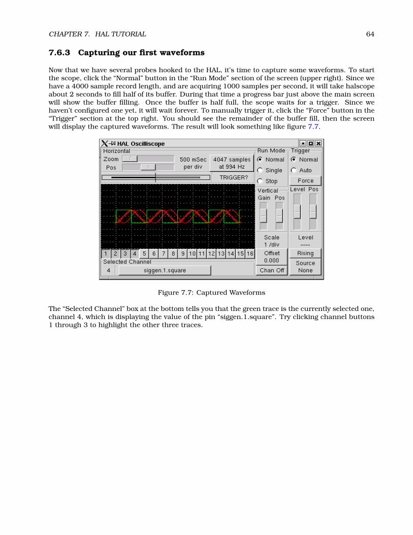
CHAPTER 7. HAL TUTORIAL 64
7.6.3 Capturing our first waveforms
Now that we have several probes hooked to the HAL, it’s time to capture some waveforms. To startthe scope, click the “Normal” button in the “Run Mode” section of the screen (upper right). Since wehave a 4000 sample record length, and are acquiring 1000 samples per second, it will take halscopeabout 2 seconds to fill half of its buffer. During that time a progress bar just above the main screenwill show the buffer filling. Once the buffer is half full, the scope waits for a trigger. Since wehaven’t configured one yet, it will wait forever. To manually trigger it, click the “Force” button in the“Trigger” section at the top right. You should see the remainder of the buffer fill, then the screenwill display the captured waveforms. The result will look something like figure 7.7.
Figure 7.7: Captured Waveforms
The “Selected Channel” box at the bottom tells you that the green trace is the currently selected one,channel 4, which is displaying the value of the pin “siggen.1.square”. Try clicking channel buttons1 through 3 to highlight the other three traces.

CHAPTER 7. HAL TUTORIAL 65
7.6.4 Vertical Adjustments
The traces are rather hard to distinguish since all four are on top of each other. To fix this, weuse the “Vertical” controls in the box to the right of the screen. These controls act on the currentlyselected channel. When adjusting the gain, notice that it covers a huge range - unlike a real scope,this one can display signals ranging from very tiny (pico-units) to very large (Tera-units). Theposition control moves the displayed trace up and down over the height of the screen only. Forlarger adjustments the offset button should be used (see the halscope reference in section 10.3 fordetails).
7.6.5 Triggering
Using the “Force” button is a rather unsatisfying way to trigger the scope. To set up real triggering,click on the “Source” button at the bottom right. It will pop up the “Trigger Source” dialog, whichis simply a list of all the probes that are currently connected (Figure 7.8 ). Select a probe to use fortriggering by clicking on it. For this example we will use channel 3, the triangle wave.
Figure 7.8: Trigger Source Dialog
After setting the trigger source, you can adjust the trigger level and trigger position using the slidersin the “Trigger” box along the right edge. The level can be adjusted from the top to the bottom of thescreen, and is displayed below the sliders. The position is the location of the trigger point within theoverall record. With the slider all the way down, the trigger point is at the end of the record, andhalscope displays what happened before the trigger point. When the slider is all the way up, thetrigger point is at the beginning of the record, displaying what happened after it was triggered. Thetrigger point is visible as a vertical line in the progress box above the screen. The trigger polaritycan be changed by clicking the button just below the trigger level display. Note that changing thetrigger position stops the scope, once the position is adjusted you restart the scope by clicking the“Normal” button in the “Run Mode” box.
Now that we have adjusted the vertical controls and triggering, the scope display looks somethinglike figure 7.9.

CHAPTER 7. HAL TUTORIAL 66
Figure 7.9: Waveforms with Triggering

CHAPTER 7. HAL TUTORIAL 67
7.6.6 Horizontal Adjustments
To look closely at part of a waveform, you can use the zoom slider at the top of the screen toexpand the waveforms horizontally, and the position slider to determine which part of the zoomedwaveform is visible. However, sometimes simply expanding the waveforms isn’t enough and youneed to increase the sampling rate. For example, we would like to look at the actual step pulsesthat are being generated in our example. Since the step pulses may be only 50uS long, samplingat 1KHz isn’t fast enough. To change the sample rate, click on the button that displays the recordlength and sample rate to bring up the “Select Sample Rate” dialog, figure . For this example, wewill click on the 50uS thread, “fast”, which gives us a sample rate of about 20KHz. Now insteadof displaying about 4 seconds worth of data, one record is 4000 samples at 20KHz, or about 0.20seconds.
Figure 7.10: Sample Rate Dialog

CHAPTER 7. HAL TUTORIAL 68
7.6.7 More Channels
Now let’s look at the step pulses. Halscope has 16 channels, but for this example we are using only4 at a time. Before we select any more channels, we need to turn off a couple. Click on the channel 2button, then click the “Off” button at the bottom of the “Vertical” box. Then click on channel 3, turnif off, and do the same for channel 4. Even though the channels are turned off, they still rememberwhat they are connected to, and in fact we will continue to use channel 3 as the trigger source.To add new channels, select channel 5, and choose pin “stepgen.1.dir”, then channel 6, and select“stepgen.1.step”. Then click run mode “Normal” to start the scope, and adjust the horizontal zoomto 5mS per division. You should see the step pulses slow down as the velocity command (channel1) approaches zero, then the direction pin changes state and the step pulses speed up again. Youmight want to increase the gain on channel 1 to about 20m per division to better see the change inthe velocity command. The result should look like figure 7.11.
Figure 7.11: Looking at Step Pulses
Chapter 8
General Reference Information
8.1 Notation
8.1.1 Typographical Conventions
Command line examples are presented in bold typewriter font. Responses from the computerwill be in typewriter font. As of early 2006, there are no longer commands that require rootprivileges, so all examples will be preceded by the normal user prompt, $. Text inside squarebrackets [like-this] is optional. Text inside angle brackets <like-this> represents a field thatcan take on different values, and the adjacent paragraph will explain the appropriate values. Textitems separated by a vertical bar means that one or the other, but not both, should be present. Allcommand line examples assume that you are in the emc2/ directory, and you configured/compiledemc2 for the run-in-place scenario. Paths will be shown accordingly when needed.
8.1.2 Names
All HAL entities are accessed and manipulated by their names, so documenting the names of pins,signals, parameters, etc, is very important. HAL names are a maximum of 41 characters long (asdefined by HAL_NAME_LEN in hal.h). Many names will be presented in a general form, with textinside angle brackets <like-this> representing fields that can take on different values.
When pins, signals, or parameters are described for the first time, their names will be preceededby their type in (SMALL CAPS) and followed by a brief description. A typical pin definition will looksomething like these examples:
• (BIT) parport.<portnum>.pin-<pinnum>-in – The HAL pin associated with the physicalinput pin <pinnum> on the 25 pin D-shell connector.
• (FLOAT) pid.<loopnum>.output – The output of the PID loop.
At times, a shortened version of a name may be used - for example the second pin above might bereferred to simply as .output when it can be done without causing confusion.
8.2 General Naming Conventions
Consistent naming conventions would make HAL much easier to use. For example, if every encoderdriver provided the same set of pins and named them the same way it would be easy to changefrom one type of encoder driver to another. Unfortunately, like many open-source projects, HAL is
69
CHAPTER 8. GENERAL REFERENCE INFORMATION 70
a combination of things that were designed, and things that simply evolved. As a result, there aremany inconsistencies. This section attempts to address that problem by defining some conventions,but it will probably be a while before all the modules are converted to follow them.
Halcmd and other low-level HAL utilities treat HAL names as single entities, with no internal struc-ture. However, most modules do have some implicit structure. For example, a board providesseveral functional blocks, each block might have several channels, and each channel has one ormore pins. This results in a structure that resembles a directory tree. Even though halcmd doesn’trecognize the tree structure, proper choice of naming conventions will let it group related itemstogether (since it sorts the names). In addition, higher level tools can be designed to recognize suchstructure, if the names provide the neccessary information. To do that, all HAL modules shouldfollow these rules:
• Dots (“.”) separate levels of the heirarchy. This is analogous to the slash (“/”) in a filename.
• Hypens (“-”) separate words or fields in the same level of the heirarchy.
• HAL modules should not use underscores or “MixedCase”. 1
• Use only lowercase letters and numbers in names.
8.3 Hardware Driver Naming Conventions2
8.3.1 Pin/Parameter names
Hardware drivers should use five fields (on three levels) to make up a pin or parameter name, asfollows:
<device-name>.<device-num>.<io-type>.<chan-num>.<specific-name>
The individual fields are:
<device-name> The device that the driver is intended to work with. This is most often an interfaceboard of some type, but there are other possibilities.
<device-num> It is possible to install more than one servo board, parallel port, or other hardwaredevice in a computer. The device number identifies a specific device. Device numbers start at0 and increment.3
<io-type> Most devices provide more than one type of I/O. Even the simple parallel port has bothdigital inputs and digital outputs. More complex boards can have digital inputs and outputs,encoder counters, pwm or step pulse generators, analog-to-digital converters, digital-to-analogconverters, or other unique capabilities. The I/O type is used to identify the kind of I/O that apin or parameter is associated with. Ideally, drivers that implement the same I/O type, even iffor very different devices, should provide a consistent set of pins and parameters and identicalbehavior. For example, all digital inputs should behave the same when seen from inside theHAL, regardless of the device.
1Underscores have all been removed, but there are still a few instances of mixed case, for example “pid.0.Pgain” insteadof “pid.0.p-gain”.
2Most drivers do not follow these conventions as of version 2.0. This chapter is really a guide for future development.3Some devices use jumpers or other hardware to attach a specific ID to each board. Ideally, the driver provides a way for
the user to specifically say “device-num 0 is the board with ID XXX”, and the device numbers always start at 0. However atpresent some drivers use the board ID directly as the device number. That means it is possible to have a device number 2,without a device 0. This is a bug and will be fixed in version 2.1.
CHAPTER 8. GENERAL REFERENCE INFORMATION 71
<chan-num> Virtually every I/O device has multiple channels, and the channel number identifiesone of them. Like device numbers, channel numbers start at zero and increment.4 If more thanone device is installed, the channel numbers on additional devices start over at zero. If it ispossible to have a channel number greater than 9, then channel numbers should be two digits,with a leading zero on numbers less than 10 to preserve sort ordering. Some modules have pinsand/or parameters that affect more than one channel. For example a PWM generator mighthave four channels with four independent “duty-cycle” inputs, but one “frequency” parameterthat controls all four channels (due to hardware limitations). The frequency parameter shoulduse “0-3” as the channel number.
<specific-name> An individual I/O channel might have just a single HAL pin associated with it,but most have more than one. For example, a digital input has two pins, one is the state ofthe physical pin, the other is the same thing inverted. That allows the configurator to choosebetween active high and active low inputs. For most io-types, there is a standard set of pinsand parameters, (referred to as the “canonical interface”) that the driver should implement.The canonical interfaces are described in chapter 9.
8.3.1.1 Examples
motenc.0.encoder.2.position – the position output of the third encoder channel on the firstMotenc board.
stg.0.din.03.in – the state of the fourth digital input on the first Servo-to-Go board.
ppmc.0.pwm.00-03.frequency – the carrier frequency used for PWM channels 0 through 3.
8.3.2 Function Names
Hardware drivers usually only have two kinds of HAL functions, ones that read the hardware andupdate HAL pins, and ones that write to the hardware using data from HAL pins. They should benamed as follows:
<device-name>-<device-num>[.<io-type>[-<chan-num-range>]].read|write
<device-name> The same as used for pins and parameters.
<device-num> The specific device that the function will access.
<io-type> Optional. A function may access all of the I/O on a board, or it may access only acertain type. For example, there may be independent functions for reading encoder countersand reading digital I/O. If such independent functions exist, the <io-type> field identifies thetype of I/O they access. If a single function reads all I/O provided by the board, <io-type> isnot used.5
<chan-num-range> Optional. Used only if the <io-type> I/O is broken into groups and accessed bydifferent functions.
read|write Indicates whether the function reads the hardware or writes to it.
4One glaring exception to the “channel numbers start at zero” rule is the parallel port. Its HAL pins are numbered withthe corresponding pin number on the DB-25 connector. This is convenient for wiring, but inconsistent with other drivers.There is some debate over whether this is a bug or a feature.
5Note to driver programmers: do NOT implement separate functions for different I/O types unless they are interruptableand can work in independent threads. If interrupting an encoder read, reading digital inputs, and then resuming the encoderread will cause problems, then implement a single function that does everything.

CHAPTER 8. GENERAL REFERENCE INFORMATION 72
8.3.2.1 Examples
motenc.0.encoder.read – reads all encoders on the first motenc board
generic8255.0.din.09-15.read – reads the second 8 bit port on the first generic 8255 baseddigital I/O board
ppmc.0.write – writes all outputs (step generators, pwm, DACs, and digital) on the first ppmcboard
Chapter 9
Canonical Device Interfaces1
The following sections show the pins, parameters, and functions that are supplied by “canonicaldevices”. All HAL device drivers should supply the same pins and parameters, and implement thesame behavior.
Note that the only the <io-type> and <specific-name> fields are defined for a canonical device.The <device-name>, <device-num>, and <chan-num> fields are set based on the characteristics ofthe real device.
9.1 Digital Input
The canonical digital input (I/O type field: digin) is quite simple.
9.1.1 Pins
• (BIT) in – State of the hardware input.
• (BIT) in-not – Inverted state of the input.
9.1.2 Parameters
• None
9.1.3 Functions
• (FUNCT) read – Read hardware and set in and in-not HAL pins.
9.2 Digital Output
The canonical digital output (I/O type field: digout) is also very simple.
9.2.1 Pins
• (BIT) out – Value to be written (possibly inverted) to the hardware output.1As of version 2.0, most of the HAL drivers don’t quite match up to the canonical interfaces defined here. In version 2.1,
the drivers will be changed to match these specs.
73
CHAPTER 9. CANONICAL DEVICE INTERFACES 74
9.2.2 Parameters
• (BIT) invert – If TRUE, out is inverted before writing to the hardware.
9.2.3 Functions
• (FUNCT) write – Read out and invert, and set hardware output accordingly.
9.3 Analog Input
The canonical analog input (I/O type: adcin). This is expected to be used for analog to digitalconverters, which convert e.g. voltage to a continuous range of values.
9.3.1 Pins
• (FLOAT) value – The hardware reading, scaled according to the scale and offset parameters.Value = ((input reading, in hardware-dependent units) * scale) - offset
9.3.2 Parameters
• (FLOAT) scale – The input voltage (or current) will be multiplied by scale before being output tovalue.
• (FLOAT) offset – This will be subtracted from the hardware input voltage (or current) after thescale multiplier has been applied.
• (FLOAT) bit_weight – The value of one least significant bit (LSB). This is effectively the granu-larity of the input reading.
• (FLOAT) hw_offset – The value present on the input when 0 volts is applied to the input pin(s).
9.3.3 Functions
• (FUNCT) read – Read the values of this analog input channel. This may be used for individualchannel reads, or it may cause all channels to be read
9.4 Analog Output
The canonical analog output (I/O Type: adcout). This is intended for any kind of hardware thatcan output a more-or-less continuous range of values. Examples are digital to analog converters orPWM generators.
Pins
• (FLOAT) value – The value to be written. The actual value output to the hardware will dependon the scale and offset parameters.
• (BIT) enable – If false, then output 0 to the hardware, regardless of the value pin.
CHAPTER 9. CANONICAL DEVICE INTERFACES 75
9.4.1 Parameters
• (FLOAT) offset – This will be added to the value before the hardware is updated
• (FLOAT) scale – This should be set so that an input of 1 on the value pin will cause 1V
• (FLOAT) high_limit (optional) – When calculating the value to output to the hardware, if value+ offset is greater than high_limit, then high_limit will be used instead.
• (FLOAT) low_limit (optional) – When calculating the value to output to the hardware, if value +offset is less than low_limit, then low_limit will be used instead.
• (FLOAT) bit_weight (optional) – The value of one least significant bit (LSB), in volts (or mA, forcurrent outputs)
• (FLOAT) hw_offset (optional) – The actual voltage (or current) that will be output if 0 is writtento the hardware.
9.4.2 Functions
(FUNCT) write – This causes the calculated value to be output to the hardware. If enable is false,then the output will be 0, regardles of value, scale, and offset. The meaning of “0” is dependent onthe hardware. For example, a bipolar 12-bit A/D may need to write 0x1FF (mid scale) to the D/Aget 0 volts from the hardware pin. If enable is true, read scale, offset and value and output to theadc (scale * value) + offset. If enable is false, then output 0.
9.5 Encoder
The canonical encoder interface (I/O type field: encoder ) provides the functionality needed forhoming to an index pulse and doing spindle synchronization, as well as basic position and/or ve-locity control. This interface should be implementable regardless of the actual underlying hardware,although some hardware will provide “better” results. (For example, capture the index position to+/- 1 count while moving faster, or have less jitter on the velocity pin.)
9.5.1 Pins
• (S32) count – Encoder value in counts.
• (FLOAT) position – Encoder value in position units (see parameter “scale”).
• (FLOAT) velocity – Velocity in position units per second.
• (BIT) reset – When True, force counter to zero.
• (BIT) index-enable – (bidirectional) When True, reset to zero on next index pulse, and set pinFalse.
The “index-enable” pin is bi-directional, and might require a little more explanation. If “index-enable” is False, the index channel of the encoder will be ignored, and the counter will countnormally. The encoder driver will never set “index-enable” True. However, some other componentmay do so. If “index-enable” is True, then when the next index pulse arrives, the encoder counterwill be reset to zero, and the driver will set “index-enable” False. That will let the other componentknow that an index pulse arrived. This is a form of handshaking - the other component sets “index-enable” True to request a index pulse reset, and the driver sets it False when the request has beensatisfied.

CHAPTER 9. CANONICAL DEVICE INTERFACES 76
9.5.2 Parameters
• (FLOAT) scale – The scale factor used to convert counts to position units. It is in “counts perposition unit”. For example, if you have a 512 count per turn encoder on a 5 turn per inchscrew, the scale should be 512*5 = 2560 counts per inch, which will result in “position” ininches and “velocity” in inches per second.
• (FLOAT) max-index-vel – (optional) The maximum velocity (in position units per second) atwhich the encoder can reset on an index pulse with +/- 1 count accuracy. This is an outputfrom the encoder driver, and is intended to tell the user something about the hardware capa-bilities. Some hardware can reset the counter at the exact moment the index pulse arrives.Other hardware can only tell that an index pulse arrived sometime since the last time the readfunction was called. For the latter, +/- 1 count accuracy can only be achieved if the encoderadvances by 1 count or less between calls to the read function.
• (FLOAT) velocity-resolution – (optional) The resolution of the velocity output, in positionunits per second. This is an output from the encoder driver, and is intended to tell the usersomething about the hardware capabilities. The simplest implementation of the velocity outputis the change in postion from one call of the read function to the next, divided by the timebetween calls. This yields a rather coarse velocity signal that jitters back and forth betweenwidely spaced possible values (quantization error). However, some hardware captures both thecounts and the exact time when a count occurres (possibly with a very high resolution clock).That data allows the driver to calculate velocity with finer resolution and less jitter.
9.5.3 Functions
There is only one function, to read the encoder(s).
• (FUNCT) read – Capture counts, update position and velocity.
Chapter 10
Tools and Utilities
10.1 Halcmd
Halcmd is a command line tool for manipulating the HAL. There is a rather complete man page forhalcmd, which will be installed if you have installed EMC2 from either source or a package. If youhave compiled EMC2 for “run-in-place”, the man page is not installed, but it is accessible. From themain EMC2 directory, do:
$ man -M docs/man halcmd
Chapter 7 has a number of examples of halcmd usage, and is a good tutorial for halcmd.
10.2 Halmeter
Halmeter is a “voltmeter” for the HAL. It lets you look at a pin, signal, or parameter, and displays thecurrent value of that item. It is pretty simple to use. Start it by typing “halmeter” in a X windowsshell. Halmeter is a GUI application. It will pop up a small window, with two buttons labeled “Select”and “Exit”. Exit is easy - it shuts down the program. Select pops up a larger window, with threetabs. One tab lists all the pins currently defined in the HAL. The next lists all the signals, and thelast tab lists all the parameters. Click on a tab, then click on a pin/signal/parameter. Then click on“OK”. The lists will disappear, and the small window will display the name and value of the selecteditem. The display is updated approximately 10 times per second. If you click “Accept” instead of“OK”, the small window will display the name and value of the selected item, but the large windowwill remain on the screen. This is convenient if you want to look at a number of different itemsquickly.
You can have many halmeters running at the same time, if you want to monitor several items. Ifyou want to launch a halmeter without tying up a shell window, type “halmeter &” to run it in thebackground. You can also make halmeter start displaying a specific item immediately, by adding“pin|sig|par[am] <name>” to the command line. It will display the pin, signal, or parameter<name> as soon as it starts. (If there is no such item, it will simply start normally.) And finally, ifyou specify an item to display, you can add “-s” before the pin|sig|param to tell halmeter to use asmall window. The item name will be displayed in the title bar instead of under the value, and therewill be no buttons. Usefull when you want a lot of meters in a small amount of screen space.
10.3 Halscope
Halscope is an “oscilloscope” for the HAL. It lets you capture the value of pins, signals, and param-eters as a function of time. Complete operating instructions should be located here eventually. For
77

CHAPTER 10. TOOLS AND UTILITIES 78
now, refer to section 7.6 in the tutorial chapter, which explains the basics.
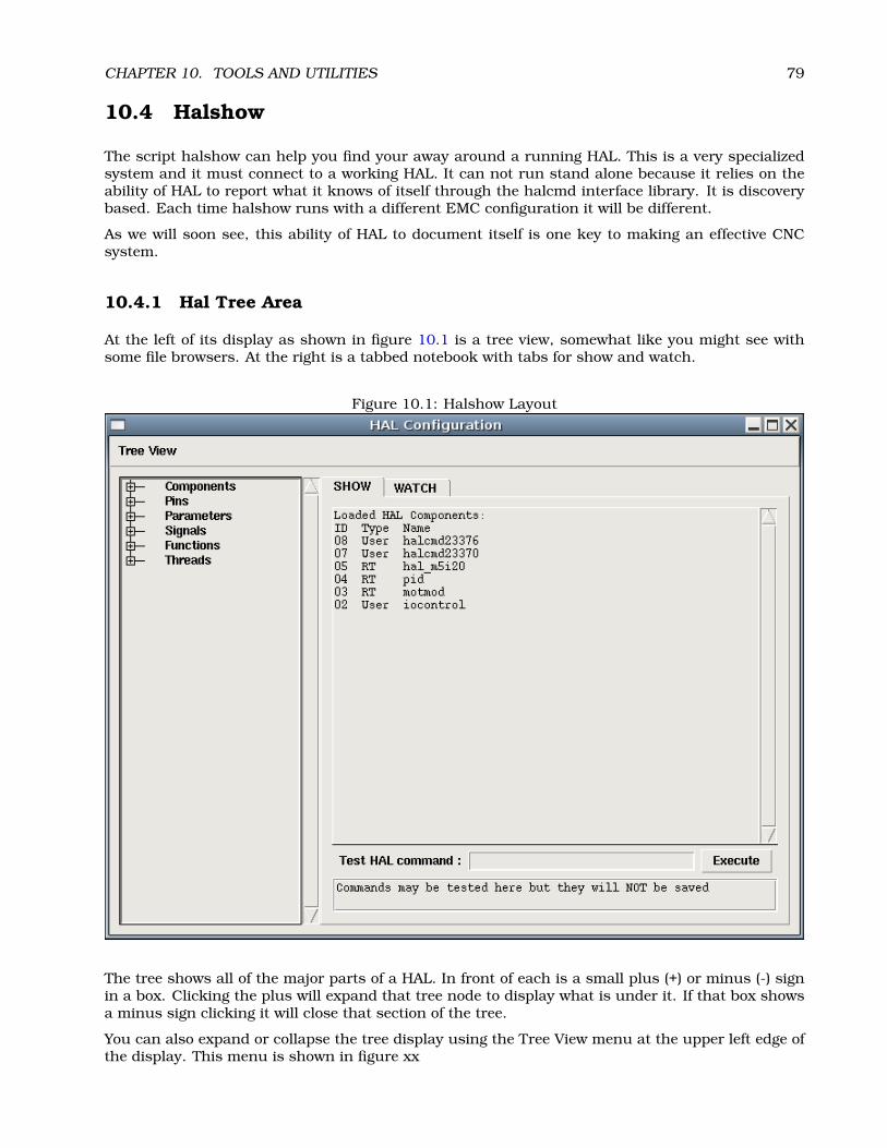
CHAPTER 10. TOOLS AND UTILITIES 79
10.4 Halshow
The script halshow can help you find your away around a running HAL. This is a very specializedsystem and it must connect to a working HAL. It can not run stand alone because it relies on theability of HAL to report what it knows of itself through the halcmd interface library. It is discoverybased. Each time halshow runs with a different EMC configuration it will be different.
As we will soon see, this ability of HAL to document itself is one key to making an effective CNCsystem.
10.4.1 Hal Tree Area
At the left of its display as shown in figure 10.1 is a tree view, somewhat like you might see withsome file browsers. At the right is a tabbed notebook with tabs for show and watch.
Figure 10.1: Halshow Layout
The tree shows all of the major parts of a HAL. In front of each is a small plus (+) or minus (-) signin a box. Clicking the plus will expand that tree node to display what is under it. If that box showsa minus sign clicking it will close that section of the tree.
You can also expand or collapse the tree display using the Tree View menu at the upper left edge ofthe display. This menu is shown in figure xx

CHAPTER 10. TOOLS AND UTILITIES 80
Figure 10.2: Show Menu
10.4.2 Hal Show Area
Clicking on the node name rather than its plus or minus sign, the word “Components” for example,will show you all that hal knows about the contents of it. Figure 10.1 shows a list exactly like youwill see if you click the “Components” name while you are running a standard m5i20 servo card.The information display is exactly like those shown in traditional text based HAL analysis tools. Theadvantage here is that we have mouse click access. Access that can be as broad or as focused asyou need.
If we take a closer look at the tree display we can see that the six major parts of a HAL can allbe expanded at least one level. As these levels are expanded you can get more focused with thereply when you click on the rightmost tree node. You will find that there are some hal pins andparameters that show more than one reply. This is do to the nature of the search routines inhalcmd itself. If you search one pin you may get two like this.
Component Pins:Owner Type Dir Value Name06 bit -W TRUE parport.0.pin-10-in06 bit -W FALSE parport.0.pin-10-in-not
The second pins name contains the complete name of the first.
Below the show area on the right is a set of widgets that will allow you to play with the runningHAL. The commands you enter here and the effect that they have on the running HAL are not saved.They will persist as long as the emc remains up but are gone as soon as it is.
The entry box labeled Test Hal Command : will accept any of the commands listed for halcmd.These include;
• loadrt, unloadrt
• addf, delf
• newsig, delsig
• linkpp, linksp, linkps, unlinkp
• setp, sets

CHAPTER 10. TOOLS AND UTILITIES 81
This little editor will enter a command any time you press <enter> or push the execute button.An error message from halcmd will show below this entry widget when these commands are notproperly formed. If you are not certain how to set up a proper command you’ll need to read againthe documentation on halcmd and the specific modules that you are working with.
Let’s use this editor to add a differential module to a hal and connect it to axis position so that wecould see the rate of change in position, ie acceleration. We first need to load a hal module namedblocks, add it to the servo thread, then connect it to the position pin of an axis. Once that is donewe can find the output of the differentiator in halscope. So let’s go. (yes I looked this one up.)
loadrt blocks ddt=1
Now look at the components node and you should see blocks in there someplace.
Loaded HAL Components:ID Type Name10 User halcmd2980009 User halcmd2937408 RT blocks06 RT hal_parport05 RT scope_rt04 RT stepgen03 RT motmod02 User iocontrol
Sure enough there it is. Notice that its id is 08. Next we need to find out what functions are availablewith it so we look at functions.
Exported Functions:Owner CodeAddr Arg FP Users Name08 E0B97630 E0DC7674 YES 0 ddt.003 E0DEF83C 00000000 YES 1 motion-command-handler03 E0DF0BF3 00000000 YES 1 motion-controller06 E0B541FE E0DC75B8 NO 1 parport.0.read06 E0B54270 E0DC75B8 NO 1 parport.0.write06 E0B54309 E0DC75B8 NO 0 parport.read-all06 E0B5433A E0DC75B8 NO 0 parport.write-all05 E0AD712D 00000000 NO 0 scope.sample04 E0B618C1 E0DC7448 YES 1 stepgen.capture-position04 E0B612F5 E0DC7448 NO 1 stepgen.make-pulses04 E0B614AD E0DC7448 YES 1 stepgen.update-freq
Here we look for owner #08 and see that blocks has exported a function named ddt.0. We should beable to add ddt.0 to the servo thread and it will do its math each time the servo thread is updated.Once again I look up the addf command and find that it uses three arguments like this.
addf <functname> <threadname> [<position>]
We already know the functname=ddt.0 so let’s get the thread name right by expanding the threadnode in the tree. Here we see two threads servo-thread and base-thread. The position of ddt.0 inthe thread is not critical.
addf ddt.0 servo-thread

CHAPTER 10. TOOLS AND UTILITIES 82
Figure 10.3: Addf Command
CHAPTER 10. TOOLS AND UTILITIES 83
This is just for viewing so we leave position blank and get the last position in the thread. Figure 10.3shows the state of halshow after this command has been issued.
Next we need to connect this block to something. But how do we know what pins are available. Theanswer is look under pins. There we find ddt and see this.
Component Pins:Owner Type Dir Value Name08 float R- 0.00000e+00 ddt.0.in08 float -W 0.00000e+00 ddt.0.out
That looks easy enough to understand but what signal or pin do we want to connect to it. It couldbe an axis pin, a stepgen pin, or a signal. I see this when I look at axis.0.
Component Pins:Owner Type Dir Value Name03 float -W 0.00000e+00 axis.0.motor-pos-cmd ==> Xpos-cmd
So it looks like Xpos-cmd should be a good signal to use. Back to the editor where I enter thefollowing command.
linksp Xpos-cmd ddt.0.in
Now if I look at the Xpos-cmd signal using the tree node I’ll see what I’ve done.
Signals:Type Value Namefloat 0.00000e+00 Xpos-cmd<== axis.0.motor-pos-cmd==> ddt.0.in==> stepgen.0.position-cmd
We see that this signal comes from axis.o.motor-pos-cmd and goes to both ddt.0.in and stepgen.0.position-cmd. By connecting our block to the signal we have avoided any complications with the normal flowof this motion command.
The Hal Show Area uses halcmd to discover what is happening in a running HAL. It gives youcomplete information about what it has discovered. It also updates as you issue commands fromthe little editor panel to modify that HAL. There are times when you want a different set of thingsdisplayed without all of the information available in this area. That is where the Hal Watch Area isof value.
10.4.3 Hal Watch Area
Clicking the watch tab produces a blank canvas. You can add signals and pins to this canvas andwatch their values.1 You can add signals or pins when the watch tab is displayed by clicking onthe name of it. Figure 10.4 shows this canvas with several “bit” type signals. These signals includeenable-out for the first three axes and two of the three iocontrol “estop” signals. Notice that theaxes are not enabled even though the estop signals say that the EMC is not in estop. A quick lookat themc shows that the condition of the EMC is ESTOP RESET. The amp enables do not turn trueuntil the machine has been turned on.
1The refresh rate of the watch display is much lower than Halmeter or Halscope. If you need good resolution of the timingof signals these tools are much more effective.
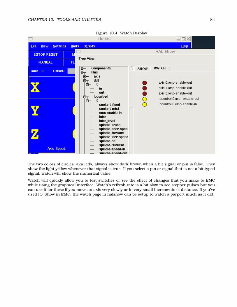
CHAPTER 10. TOOLS AND UTILITIES 84
Figure 10.4: Watch Display
The two colors of circles, aka leds, always show dark brown when a bit signal or pin is false. Theyshow the light yellow whenever that signal is true. If you select a pin or signal that is not a bit typedsignal, watch will show the numerical value.
Watch will quickly allow you to test switches or see the effect of changes that you make to EMCwhile using the graphical interface. Watch’s refresh rate is a bit slow to see stepper pulses but youcan use it for these if you move an axis very slowly or in very small increments of distance. If you’veused IO_Show in EMC, the watch page in halshow can be setup to watch a parport much as it did.
Chapter 11
comp: a tool for creating HALmodules
11.1 Introduction
Writing a HAL component can be a tedious process, most of it in setup calls to rtapi_ and hal_functions and associated error checking. comp will write all this code for you, automatically.
Compiling a realtime HAL component is also much easier when using comp, whether the componentis part of the emc2 source tree, or outside it.
For instance, the “ddt” portion of blocks is around 80 lines of code. The equivalent component isvery short when written using the comp preprocessor:
component ddt “Compute the derivative of the input function”;pin in float in;pin out float out;option data float;function _;;;MODULE_LICENSE("GPL");FUNCTION(_)
float tmp = in;out = (tmp - data) / fperiod;data = tmp;
and it can be compiled and installed very easily: by simply placing ddt.comp in src/hal/componentsand running ’make’, or by placing it anywhere on the system and running comp --install ddt.comp
11.2 Definitions
component A component is a single real-time module, which is loaded with halcmd loadrt. One.comp file specifies one component.
instance A component can have zero or more instances. Each instance of a component is createdequal (they all have the same pins, parameters, functions, and data) but behave independentlywhen their pins, parameters, and data have different values.
85
CHAPTER 11. COMP: A TOOL FOR CREATING HAL MODULES 86
singleton It is possible for a component to be a ’singleton’, in which case exactly one instance iscreated. It seldom makes sense to write a singleton component, unless there can literallyonly be a single object of that kind in the system (for instance, a component whose purpose isto provide a pin with the current UNIX time, or a hardware driver for the internal PC speaker)
11.3 Instance creation
For a singleton, the one instance is created when the component is loaded.
For a non-singleton, the ’count’ module parameter determines how many numbered instances arecreated.
11.4 Syntax
A .comp file consists of a number of declarations, followed by ;; on a line of its own, followed by Ccode implementing the module’s realtime functions.
Declarations include:
component NAME [DOC];pin PINDIRECTION TYPE NAME [DOC];param PARAMDIRECTION TYPE NAME [= STARTVALUE] [DOC] ;function NAME [fp | nofp] [DOC];option NAME [VALUE];
Brackets indicate optional items. A vertical bar indicates alternatives. Words in CAPITALS indicatevariable text, as follows:
NAME A C identifier.When used to create a HAL identifier, any underscores are replaced with dashes, and anytrailing dash is removed, so that “this_name_” will be turned into “this-name”. If the name is“_”, then a trailing period is removed as well, so that “function _” gives a HAL function namelike component.<num> instead of component.<num>.If present, the prefix hal_ is removed from the beginning of the component name when creatingpins, parameters and functions.
DOC A string that documents the item. String can be a C-style “double quoted” string, like"Selects the desired edge: TRUE means falling, FALSE means rising" or a Python-style “triple quoted” string, which may include embedded newlines and quote characters, suchas:
param rw bit zot=TRUE"""The effect of this parameter, also known as "the orb of zot",will require at least two paragraphs to explain.
Hopefully these paragraphs have allowed you to understand "zot"better.""";
TYPE One of the HAL types: bit, s32, u32, or float.
PINDIRECTION One of the following: in, out, or io. A component sets a value for an out pin, itreads a value from an in pin, and it may read or set the value of an io pin.
PARAMDIRECTION One of the following: r or rw. A component sets a value for a r parameter, andit may read or set the value of a rw parameter.

CHAPTER 11. COMP: A TOOL FOR CREATING HAL MODULES 87
STARTVALUE Specifies the initial value of a parameter. If it is not specified, then the default is 0or FALSE, depending on the type of the parameter.
fp Indicates that the function performs floating-point calculations.
nofp Indicates that it only performs integer calculations. If neither is specified, fp is assumed.Neither comp nor gcc can detect the use of floating-point calculations in functions that aretagged nofp.
VALUE Depending on the option name, the valid VALUEs vary. The currently defined options are:
option singleton yes (default: no)Do not create a count module parameter, and always create a single instance. Withsingleton, items are named component-name.item-name and without singleton, itemsfor numbered instances are named component-name.<num>.item-name.
option default_count (default: 1)Normally, the module parameter count defaults to 0. If specified, the count will defaultto this value instead.
option count_function yes (default: no)Normally, the number of instances to create is specified in the module parameter count; ifcount_function is specified, the value returned by the function int get_count(void)is used instead, and the count module parameter is not defined.
option rtapi_app no (default: yes)Normally, the functions rtapi_app_main and rtapi_app_exit are automatically defined.With option rtapi_app no, they are not, and must be provided in the C code.When implementing your own rtapi_app_main, call the function int export(char *prefix,long extra_arg) to register the pins, parameters, and functions for prefix.
option data type (default: none)If specified, each instance of the component will have an associated data block of type(which can be a simple type like float or the name of a type created with typedef).
option extra_setup yes (default: no)If specified, call the function defined by EXTRA_SETUP for each instance. If using theautomatically defined rtapi_app_main, extra_arg is the number of this instance.
option extra_cleanup yes (default: no)If specified, call the function defined by EXTRA_CLEANUP from the automatically definedrtapi_app_exit, or if an error is detected in the automatically defined rtapi_app_main.
If an option’s VALUE is not specified, then it is equivalent to specifying option ... yes. Theresult of assigning an inappropriate value to an option is undefined. The result of using anyother option is undefined.
C++-style one-line comments (// ...) and C-style multi-line comments (/* ... */) are bothsupported in the declaration section.
11.5 Other restrictions on comp files
Though HAL permits a pin, a parameter, and a function to have the same name, comp does not.
11.6 Convenience Macros
Based on the items in the declaration section, comp creates a C structure called struct state.However, instead of referring to the members of this structure (e.g., *(inst->name)), they willgenerally be referred to using the macros below. The details of struct state and these macrosmay change from one version of comp to the next.

CHAPTER 11. COMP: A TOOL FOR CREATING HAL MODULES 88
FUNCTION(name) Use this macro to begin the definition of a realtime function which was previ-ously declared with ’function NAME’. The function includes a parameter ’period’ which is theinteger number of nanoseconds between calls to the function.
EXTRA_SETUP() Use this macro to begin the definition of the function called to perform extra setupof this instance. Return a negative Unix errno value to indicate failure (e.g., return -EBUSYon failure to reserve an I/O port), or 0 to indicate success.
EXTRA_CLEANUP() Use this macro to begin the definition of the function called to perform extracleanup of the component. Note that this function must clean up all instances of the com-ponent, not just one. The ’pin_name’, ’parameter_name’, and ’data’ macros may not be usedhere.
pin_name
parameter_name For each pin pin_name or param parameter_name there is a macro which allowsthe name to be used on its own to refer to the pin or parameter.
data If ’option data’ is specified, this macro allows access to the instance data.
fperiod The floating-point number of seconds between calls to this function.
11.7 Compiling .comp files in the source tree
Place the .comp file in the source directory emc2/src/hal/components and re-run make. Comp filesare automatically detected by the build system.
If a .comp file is a driver for hardware, it may be placed in emc2/src/hal/components and will bebuilt except if emc2 is configured as a userspace simulator.
11.8 Compiling components outside the source tree
comp can process, compile, and install a component in a single step, placing example.ko in theemc2 realtime module directory:
comp --install example.comp
Or, it can process and compile in one step, leaving example.ko in the current directory:
comp --compile example.comp
Or it can simply process, leaving example.c in the current directory:
comp example.comp
comp can also compile and install a component written in C, using the --install and --compileoptions shown above:
comp --install example2.c
man-format documentation can also be created from the information in the declaration section:
comp --document example.comp
The resulting manpage, example.9 can be viewed with
man ./example.9
or copied to a standard location for manual pages.

CHAPTER 11. COMP: A TOOL FOR CREATING HAL MODULES 89
11.9 Examples
11.9.1 constant
This component functions like the one in ’blocks’, including the default value of 1.0. The declaration“function _” creates functions named ’constant.0’, etc.
component constant;pin out float out;param r float value = 1.0;function _;option extra_setup yes;;;FUNCTION(_) out = value;
11.9.2 sincos
This component computes the sine and cosine of an input angle in radians. It has different ca-pabilities than the ’sine’ and ’cosine’ outputs of siggen, because the input is an angle, rather thanrunning freely based on a ’frequency’ parameter.
The pins are declared with the names sin_ and cos_ in the source code so that they do not interferewith the functions sin() and cos(). The HAL pins are still called sincos.<num>.sin.
component sincos;pin out float sin_ out;pin out float cos_ out;pin in float theta in;function _;;;#include <rtapi_math.h>FUNCTION(_) sin_ = sin(theta); cos_ = cos(theta);
11.9.3 out8
This component is a driver for a fictional card called “out8”, which has 8 pins of digital outputwhich are treated as a single 8-bit value. There can be a varying number of such cards in thesystem, and they can be at various addresses. The pin is called out_ because out is an identifierused in <asm/io.h>. It illustrates the use of EXTRA_SETUP and EXTRA_CLEANUP to request an I/Oregion and then free it in case of error or when the module is unloaded.
component out8;pin out u32 out_ "Output value; only low 8 bits are used";param r u32 ioaddr;
function _;
option count_function;option extra_setup;option extra_cleanup;option constructable no;
;;

CHAPTER 11. COMP: A TOOL FOR CREATING HAL MODULES 90
#include <asm/io.h>
#define MAX 8int io[MAX] = 0,;RTAPI_MP_ARRAY_INT(io, MAX, "I/O addresses of out8 boards");
int get_count(void) int i = 0;for(i=0; i<MAX && io[i]; i++) /* Nothing */ return i;
EXTRA_SETUP() if(!rtapi_request_region(io[extra_arg], 1, "out8"))
// set this I/O port to 0 so that EXTRA_CLEANUP does not release the IO// ports that were never requested.
io[extra_arg] = 0;return -EBUSY;
ioaddr = io[extra_arg];return 0;
EXTRA_CLEANUP() int i;for(i=0; i < MAX && io[i]; i++)
rtapi_release_region(io[i], 1);
FUNCTION(_) outb(out_, ioaddr);
11.9.4 hal_loop
component hal_loop;pin out float example;
This fragment of a component illustrates the use of the hal_ prefix in a component name. loop isthe name of a standard Linux kernel module, so a loop component might not successfully load ifthe Linux loop module was also present on the system.
When loaded, halcmd show comp will show a component called hal_loop. However, the pin shownby halcmd show pin will be loop.0.example, not hal-loop.0.example.

Chapter 12
Creating Userspace PythonComponents with the ’hal’ module
12.1 Basic usage
A userspace component begins by creating its pins and parameters, then enters a loop which willperiodically drive all the outputs from the inputs. The following component copies the value seenon its input pin (passthrough.in) to its output pin (passthrough.out) approximately once persecond.
#!/usr/bin/pythonimport hal, timeh = hal.component("passthrough")h.newpin("in", hal.HAL_FLOAT, hal.HAL_IN)h.newpin("out", hal.HAL_FLOAT, hal.HAL_OUT)h.ready()try:
while 1:time.sleep(1)h[’out’] = h[’in’]
except KeyboardInterrupt:raise SystemExit
Copy the above listing into a file named “passthrough”, make it executable (chmod +x), and placeit on your $PATH. Then try it out:
$ halrunhalcmd: loadusr passthroughhalcmd: show pinComponent Pins:Owner Type Dir Value Name03 float IN 0 passthrough.in03 float OUT 0 passthrough.out
halcmd: setp passthrough.in 3.14halcmd: show pinComponent Pins:Owner Type Dir Value Name03 float IN 3.14 passthrough.in03 float OUT 3.14 passthrough.out
91
CHAPTER 12. CREATING USERSPACE PYTHON COMPONENTS WITH THE ’HAL’ MODULE 92
12.2 Userspace components and delays
If you typed “show pin” quickly, you may see that passthrough.out still had its old value of 0. Thisis because of the call to ’time.sleep(1)’, which makes the assignment to the output pin occur at mostonce per second. Because this is a userspace component, the actual delay between assignmentscan be much longer–for instance, if the memory used by the passthrough component is swapped todisk, the assignment could be delayed until that memory is swapped back in.
Thus, userspace components are suitable for user-interactive elements such as control panels (de-lays in the range of milliseconds are not noticed, and longer delays are acceptable), but not forsending step pulses to a stepper driver board (delays must always be in the range of microseconds,no matter what).
12.3 Create pins and parameters
h = hal.component("passthrough")
The component itself is created by a call to the constructor ’hal.component’. The arguments arethe HAL component name and (optionally) the prefix used for pin and parameter names. If the prefixis not specified, the component name is used.
h.newpin("in", hal.HAL_FLOAT, hal.HAL_IN)
Then pins are created by calls to methods on the component object. The arguments are: pin namesuffix, pin type, and pin direction. For parameters, the arguments are: parameter name suffix,parameter type, and parameter direction.
Table 12.1: HAL Option NamesPin and Parameter Types: HAL_BIT HAL_FLOAT HAL_S32 HAL_U32
Pin Directions: HAL_IN HAL_OUT HAL_IOParameter Directions: HAL_RO HAL_RW
The full pin or parameter name is formed by joining the prefix and the suffix with a “.”, so in theexample the pin created is called passthrough.in.
h.ready()
Once all the pins and parameters have been created, call the .ready() method.
12.3.1 Changing the prefix
The prefix can be changed by calling the .setprefix() method. The current prefix can be retrievedby calling the .getprefix() method.
12.4 Reading and writing pins and parameters
For pins and parameters which are also proper Python identifiers, the value may be accessed or setusing the attribute syntax:
h.out = h.in
For all pins, whether or not they are also proper Python identifiers, the value may be accessed orset using the subscript syntax:
h[’out’] = h[’in’]

CHAPTER 12. CREATING USERSPACE PYTHON COMPONENTS WITH THE ’HAL’ MODULE 93
12.4.1 Driving output (HAL_OUT) pins
Periodically, usually in response to a timer, all HAL_OUT pins should be “driven” by assigning thema new value. This should be done whether or not the value is different than the last one assigned.When a pin is connected to a signal, its old output value is not copied into the signal, so the propervalue will only appear on the signal once the component assigns a new value.
12.4.2 Driving bidirectional (HAL_IO) pins
The above rule does not apply to bidirectional pins. Instead, a bidirectional pin should only be drivenby the component when the component wishes to change the value. For instance, in the canonicalencoder interface, the encoder component only sets the index-enable pin to FALSE (when an indexpulse is seen and the old value is TRUE), but never sets it to TRUE. Repeatedly driving the pinFALSE might cause the other connected component to act as though another index pulse had beenseen.
12.5 Exiting
A “halcmd unload” request for the component is delivered as a KeyboardInterrupt exception.When an unload request arrives, the process should either exit in a short time, or call the .exit()method on the component if substantial work (such as reading or writing files) must be done tocomplete the shutdown process.
12.6 Project ideas
• Create an external control panel with buttons, switches, and indicators. Connect everythingto a microcontroller, and connect the microcontroller to the PC using a serial interface. Pythonhas a very capable serial interface module called pyserial http://pyserial.sourceforge.net/ (Ubuntu package name “python-serial”, in the universe repository)
• Attach a LCDProc http://lcdproc.omnipotent.net/-compatible LCD module and use it todisplay a digital readout with information of your choice (Ubuntu package name “lcdproc”, inthe universe repository)
• Create a virtual control panel using any GUI library supported by Python (gtk, qt, wxwindows,etc)
Part V
EMC related HAL
94

Chapter 13
Basic configurations for a stepperbased system
13.1 Introduction
This chapter describes some of the more common settings that users want to change when settingup EMC2. Because of the various possibilities of configuring EMC2, it is very hard to documentthem all, and keep this document relatively short.
The most common EMC2 usage (as reported by our users) is for stepper based systems. Thesesystems are using stepper motors with drives that accept step & direction signals.
It is one of the simpler setups, because the motors run open-loop (no feedback comes back from themotors), yet the system needs to be configured properly so the motors don’t stall or lose steps.
Most of this chapter is based on the sample config released along with EMC2. The config is calledstepper, and usually it is found in /etc/emc2/sample-configs/stepper.
13.2 Maximum step rate
With software step generation, the maximum step rate is one step per two BASE_PERIODs for step-and-direction output. The maximum requested step rate is the product of an axis’s MAX_VELOCITYand its INPUT_SCALE. If the requested step rate is not attainable, following errors will occur, par-ticularly during fast jogs and G0 moves.
If your stepper driver can accept quadrature input, use this mode. With a quadrature signal, onestep is possible for each BASE_PERIOD, doubling the maximum step rate.
The other remedies are to decrease one or more of: the BASE_PERIOD (setting this too low will causethe machine to become unresponsive or even lock up), the INPUT_SCALE (if you can select differentstep sizes on your stepper driver, change pulley ratios, or leadscrew pitch), or the MAX_VELOCITYand STEPGEN_MAXVEL.
If no valid combination of BASE_PERIOD, INPUT_SCALE, and MAX_VELOCITY is acceptable, thenhardware step generation (such as with the emc2-supported Universal Stepper Controller)
13.3 Pinout
One of the majour flaws in EMC was that you couldn’t specify the pinout without recompiling thesource code. EMC2 is far more flexible, and now (thanks to the Hardware Abstraction Layer) you
95

CHAPTER 13. BASIC CONFIGURATIONS FOR A STEPPER BASED SYSTEM 96
can easily specify which signal goes where. (read the 6.1 section for more information about theHAL).
As it is described in the HAL Introduction and tutorial, we have signals, pins and parameters insidethe HAL.
The ones relevant for our pinout are1:
signals: Xstep, Xdir & Xenpins: parport.0.pin-XX-out & parport.0.pin-XX-in 2
Depending on what you have chosen in your ini file you are using either standard_pinout.hal orxylotex_pinout.hal. These are two files that instruct the HAL how to link the various signals & pins.Furtheron we’ll investigate the standard_pinout.hal.
13.3.1 standard_pinout.hal
This file contains several HAL commands, and usually looks like this:
# standard pinout config file for 3-axis steppers# using a parport for I/O## first load the parport driverloadrt hal_parport cfg="0x0378"## next connect the parport functions to threads# read inputs firstaddf parport.0.read base-thread 1# write outputs lastaddf parport.0.write base-thread -1## finally connect physical pins to the signalslinksp Xstep => parport.0.pin-03-outlinksp Xdir => parport.0.pin-02-outlinksp Ystep => parport.0.pin-05-outlinksp Ydir => parport.0.pin-04-outlinksp Zstep => parport.0.pin-07-outlinksp Zdir => parport.0.pin-06-out
# create a signal for the estop loopbacklinkpp iocontrol.0.user-enable-out iocontrol.0.emc-enable-in
# create signals for tool loading loopbacklinkpp iocontrol.0.tool-prepare iocontrol.0.tool-preparedlinkpp iocontrol.0.tool-change iocontrol.0.tool-changed
# create a signal for "spindle on"newsig spindle-on bit# connect the controller to itlinkps motion.spindle-on => spindle-on# connect it to a physical pinlinksp spindle-on => parport.0.pin-09-out
1Note: we are only presenting one axis to keep it short, all others are similar.2Refer to section 15.1 for additional information

CHAPTER 13. BASIC CONFIGURATIONS FOR A STEPPER BASED SYSTEM 97
###### You might use something like this to enable chopper drives when machine ON### the Xen signal is defined in core_stepper.hal###
# linksp Xen => parport.0.pin-01-out
###### If you want active low for this pin, invert it like this:###
# setp parport.0.pin-01-out-invert 1
###### A sample home switch on the X axis (axis 0). make a signal,### link the incoming parport pin to the signal, then link the signal### to EMC’s axis 0 home switch input pin###
# newsig Xhome bit# linkps parport.0.pin-10-in => Xhome# linksp Xhome => axis.0.home-sw-in
###### Shared home switches all on one parallel port pin?### that’s ok, hook the same signal to all the axes, but be sure to### set HOME_IS_SHARED and HOME_SEQUENCE in the ini file. See the### user manual!###
# newsig homeswitches bit# linkps parport.0.pin-10-in => homeswitches# linksp homeswitches => axis.0.home-sw-in# linksp homeswitches => axis.1.home-sw-in# linksp homeswitches => axis.2.home-sw-in
###### Sample separate limit switches on the X axis (axis 0)###
# newsig X-neg-limit bit# linkps parport.0.pin-11-in => X-neg-limit# linksp X-neg-limit => axis.0.neg-lim-sw-in
# newsig X-pos-limit bit# linkps parport.0.pin-12-in => X-pos-limit# linksp X-pos-limit => axis.0.pos-lim-sw-in
###### Just like the shared home switches example, you can wire together### limit switches. Beware if you hit one, EMC will stop but can’t tell### you which switch/axis has faulted. Use caution when recovering from this.###
# newsig Xlimits bit# linkps parport.pin-13-in => Xlimits

CHAPTER 13. BASIC CONFIGURATIONS FOR A STEPPER BASED SYSTEM 98
# linksp Xlimits => axis.0.neg-lim-sw-in# linksp Xlimits => axis.0.pos-lim-sw-in
###### you can also use the "net" syntax to accomplish the "newsig" and "link"### operations all at once. This command does the same thing as the above### block.###
# net Xlimits parport.pin-13-in => axis.0.neg-lim-sw-in axis.0.pos-lim-sw-in
The files starting with ’#’ are comments, and their only purpose is to guide the reader through thefile.
13.3.2 Overview of the standard_pinout.hal
There are a couple of operations that get executed when the standard_pinout.hal gets executed /interpreted:
1. The Parport driver gets loaded (see 15.1 for details)
2. The read & write functions of the parport driver get assigned to the Base thread 3
3. The step & direction signals for axes X,Y,Z get linked to pins on the parport
4. Further IO signals get connected (estop loopback, toolchanger loopback)
5. A spindle On signal gets defined and linked to a parport pin
13.3.3 Changing the standard_pinout.hal
If you want to change the standard_pinout.hal file, all you need is a text editor. Open the file andlocate the parts you want to change.
If you want for example to change the pin for the X-axis Step & Directions signals, all you need todo is to change the number in the ’parport.0.pin-XX-out’ name:
linksp Xstep parport.0.pin-03-outlinksp Xdir parport.0.pin-02-out
can be changed to:
linksp Xstep parport.0.pin-02-outlinksp Xdir parport.0.pin-03-out
or basicly any other numbers you like.
Hint: make sure you don’t have more than one signal connected to the same pin.
13.3.4 Changing the polarity of a signal
If external hardware expects an “active low” signal, set the corresponding -invert parameter. Forinstance, to invert the spindle control signal:
setp parport.0.pin-09-invert TRUE
3the fastest thread in the EMC2 setup, usually the code gets executed every few microseconds

CHAPTER 13. BASIC CONFIGURATIONS FOR A STEPPER BASED SYSTEM 99
13.3.5 Adding PWM Spindle Speed Control
If your spindle can be controlled by a PWM signal, use the pwmgen component to create the signal:
loadrt pwmgen output_type=0addf pwmgen.update servo-threadaddf pwmgen.make-pulses base-threadnet spindle-speed-cmd motion.spindle-speed-out => pwmgen.0.valuenet spindle-on motion.spindle-on => pwmgen.0.enablenet spindle-pwm pwmgen.0.pwm => parport.0.pin-09-outsetp pwmgen.0.scale 1800 # Change to your spindle’s top speed in RPM
This assumes that the spindle controller’s response to PWM is simple: 0% PWM gives 0RPM, 10%PWM gives 180 RPM, etc. If there is a minimum PWM required to get the spindle to turn, follow theexample in the nist-lathe sample configuration to use a scale component.
13.3.6 Adding an enable signal
Some amplifiers (drives) require an enable signal before they accept and command movement of themotors. For this reason there are already defined signals called ’Xen’, ’Yen’, ’Zen’.
To connect them use the following example:
linksp Xen parport.0.pin-08-out
You can either have one single pin that enables all drives, or several, depending on the setup youhave. Note however that usually when one axis faults, all the other ones will be disabled aswell, sohaving only one signal / pin is perfectly safe.
13.3.7 Adding an external ESTOP button
As you can see in 13.3.1 by default the stepper configuration assumes no external ESTOP button. 4
To add a simple external button you need to replace the line:
linkpp iocontrol.0.user-enable-out iocontrol.0.emc-enable-in
with
linkpp parport.0.pin-01-in iocontrol.0.emc-enable-in
This assumes an ESTOP switch connected to pin 01 on the parport. As long as the switch willstay pushed5, EMC2 will be in the ESTOP state. When the external button gets released EMC2 willimediately switch to the ESTOP-RESET state, and all you need to do is switch to Machine On andyou’ll be able to continue your work with EMC2.
4An extensive explanation of hooking up ESTOP circuitry is explained in the wiki.linuxcnc.org and in the IntegratorManual
5make sure you use a maintained switch for ESTOP.
Chapter 14
Internal Components
14.1 Stepgen
This component provides software based generation of step pulses in response to position com-mands. It has a built in pre-tuned position loop, so PID tuning is not required. This component isstrongly recommended for stepper based EMC machines, since it eliminates the need to use (andtune) a separate PID loop. It is a realtime component only, and depending on CPU speed, etc, is ca-pable of maximum step rates of 10kHz to perhaps 50kHz. Figure 14.1 shows three block diagrams,each is a single step pulse generator. The first diagram is for step type ’0’, (step and direction). Thesecond is for step type ’1’ (up/down, or pseudo-PWM), and the third is for step types 2 through 14(various stepping patterns).
14.1.1 Installing
emc2$ halcmd loadrt stepgen step_type=<config-array>
<config-array> is a series of comma separated decimal integers. Each number causes a singlestep pulse generator to be loaded, the value of the number determines the stepping type. Forexample:
emc2# halcmd loadrt stepgen.o step_type=0,0,2
will install three step generators, two with step type ’0’ (step and direction) and one with step type’2’ (quadrature). The default value for <config-array> is “0,0,0” which will install three type ’0’(step/dir) generators. The maximum number of step generators is 8 (as defined by MAX_CHAN instepgen.c). Each generator is independent, but all are updated by the same function(s) at the sametime. In the following descriptions, <chan> is the number of a specific generator. The first generatoris number 0.
14.1.2 Removing
emc2$ halcmd unloadrt stepgen
14.1.3 Pins
Each step pulse generator will have only some of these pins, depending on the step type selected.
100

CHAPTER 14. INTERNAL COMPONENTS 101
position-cmd
position-cmd
position-cmd
phase-B
phase-E
phase-D
down
step
phase-A
phase-C
up
dir
counts
counts
counts
position-fb
position-fb
position-fb
maxaccel
maxaccel
maxaccel
maxfreq
maxfreq
maxfreq
frequencygenerator
frequencygenerator
frequencygenerator
statecounter
lookuptable
ramp
ramp
ramp
latch
latch
latch
counter
counter
counter
step/dirlogicand
timing
vel-err
vel-err
vel-err
pos-err
pos-err
pos-err
frequency
frequency
frequency
stepspace
dirsetup
dirhold
steplen
rawcounts
rawcounts
rawcounts
position-scale
position-scale
position-scale
d
d
d
dT
dT
dT
up/dn
up/dn
up/dn
up/dn
up/dn
up/dn
count
count
count
count
count
count
make_pulses()
make_pulses()
make_pulses()
STEP TYPE = 1
STEP TYPE = 2 - 14
STEP TYPE = 0
update_freq()
update_freq()
update_freq()
capture_position()
capture_position()
capture_position()
stepgen.0
stepgen.0
stepgen.0
1/x
1/x
1/x
1 count
1 count
1 count
controlequation
controlequation
controlequation
Figure 14.1: Step Pulse Generator Block Diagram

CHAPTER 14. INTERNAL COMPONENTS 102
• (FLOAT) stepgen.<chan>.position-cmd – Desired motor position, in position units (inches,mm, etc).
• (S32) stepgen.<chan>.count – Feedback position in counts, updated by capture_position().
• (FLOAT) stepgen.<chan>.position-fb – Feedback position in position units, updated bycapture_position().
• (BIT) stepgen.<chan>.step – Step pulse output (step type 0 only).
• (BIT) stepgen.<chan>.dir – Direction output (step type 0 only).
• (BIT) stepgen.<chan>.up – UP pseudo-PWM output (step type 1 only).
• (BIT) stepgen.<chan>.down – DOWN pseudo-PWM output (step type 1 only).
• (BIT) stepgen.<chan>.phase-A – Phase A output (step types 2-14 only).
• (BIT) stepgen.<chan>.phase-B – Phase B output (step types 2-14 only).
• (BIT) stepgen.<chan>.phase-C – Phase C output (step types 3-14 only).
• (BIT) stepgen.<chan>.phase-D – Phase D output (step types 5-14 only).
• (BIT) stepgen.<chan>.phase-E – Phase E output (step types 11-14 only).
14.1.4 Parameters
• (FLOAT) stepgen.<chan>.position-scale – Steps per position unit. This parameter is usedfor both output and feedback.
• (FLOAT) stepgen.<chan>.maxfreq – Maximum step rate, in steps per second. If 0.0, has noeffect.
• (FLOAT) stepgen.<chan>.maxaccel – Maximum accel/decel rate, in steps per second squared.If 0.0, has no effect.
• (FLOAT) stepgen.<chan>.pos-err – The position error - difference between commanded andactual position, in steps.
• (FLOAT) stepgen.<chan>.vel-err – The velocity error - in steps per second.
• (FLOAT) stepgen.<chan>.frequency – The current step rate, in steps per second. This is theoutput of the position loop.
• (FLOAT) stepgen.<chan>.steplen – Length of a step pulse (step type 0 only).
• (FLOAT) stepgen.<chan>.stepspace – Minimum spacing between two step pulses (step type0 only).
• (FLOAT) stepgen.<chan>.dirsetup – Minimum time from a direction change to the begin-ning of the next step pulse (step type 0 only).
• (FLOAT) stepgen.<chan>.dirhold – Minmum time from the end of a step pulse to a directionchange (step type 0 only).
• (S32) stepgen.<chan>.rawcounts – The raw feedback count, updated by make_pulses().
The values of maxfreq and maxaccel are used by the internal position loop to avoid generating steppulse trains that the motor cannot follow. When set to values that are appropriate for the motor,even a large instantaneous change in commanded position will result in a smooth trapezoidal moveto the new location. The algorithm works by measuring both position error and velocity error, andcalculating an acceleration that attempts to reduce both to zero at the same time. For more details,including the contents of the “control equation” box, consult the code.
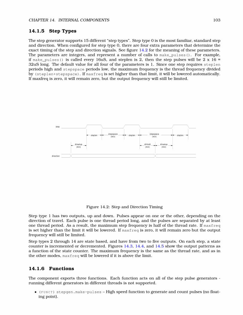
CHAPTER 14. INTERNAL COMPONENTS 103
14.1.5 Step Types
The step generator supports 15 different “step types”. Step type 0 is the most familiar, standard stepand direction. When configured for step type 0, there are four extra parameters that determine theexact timing of the step and direction signals. See figure 14.2 for the meaning of these parameters.The parameters are integers, and represent a number of calls to make_pulses(). For example,if make_pulses() is called every 16uS, and steplen is 2, then the step pulses will be 2 x 16 =32uS long. The default value for all four of the parameters is 1. Since one step requires steplenperiods high and stepspace periods low, the maximum frequency is the thread frequency dividedby (steplen+stepspace). If maxfreq is set higher than that limit, it will be lowered automatically.If maxfreq is zero, it will remain zero, but the output frequency will still be limited.
step lenstep len s tepspace(min)
s tepspace(min)
di rsetup(min)
di rsetup(min)
dirhold(min)
s tep len
step
direct ion
Figure 14.2: Step and Direction Timing
Step type 1 has two outputs, up and down. Pulses appear on one or the other, depending on thedirection of travel. Each pulse is one thread period long, and the pulses are separated by at leastone thread period. As a result, the maximum step frequency is half of the thread rate. If maxfreqis set higher than the limit it will be lowered. If maxfreq is zero, it will remain zero but the outputfrequency will still be limited.
Step types 2 through 14 are state based, and have from two to five outputs. On each step, a statecounter is incremented or decremented. Figures 14.3, 14.4, and 14.5 show the output patterns asa function of the state counter. The maximum frequency is the same as the thread rate, and as inthe other modes, maxfreq will be lowered if it is above the limit.
14.1.6 Functions
The component exports three functions. Each function acts on all of the step pulse generators -running different generators in different threads is not supported.
• (FUNCT) stepgen.make-pulses – High speed function to generate and count pulses (no float-ing point).

CHAPTER 14. INTERNAL COMPONENTS 104
0
0
0
1
1
1
2
2
2
1
4
0
0
3
3
2
5
1
0
0
2
1
1
3
2
2
0
0
3 4
STEP TYPE 3
STEP TYPE 4
STEP TYPE 2
phase-A
phase-A
phase-A
phase-B
phase-B
phase-B
phase-C
phase-C
Figure 14.3: Quadrature and Three Phase Step Types
• (FUNCT) stepgen.update-freq – Low speed function does position to velocity conversion,scaling and limiting.
• (FUNCT) stepgen.capture-position – Low speed function for feedback, updates latches andscales position.
The high speed function stepgen.make-pulses should be run in a very fast thread, from 10 to50uS depending on the capabilities of the computer. That thread’s period determines the maximumstep frequency, and is also the time unit used by the length, space, setup, and hold parameters(step type 0). The other two functions can be called at a much lower rate.
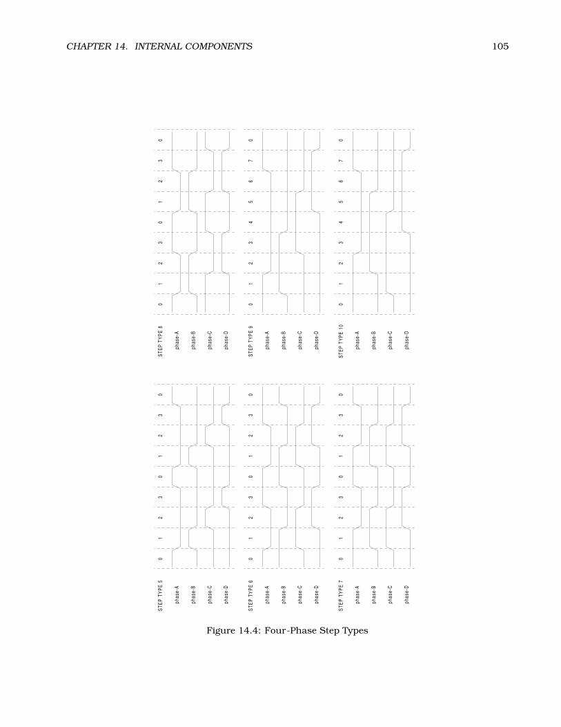
CHAPTER 14. INTERNAL COMPONENTS 105
0 0
00
0 0
1 1
11
1 1
2 2
22
2 2
0 0
00
4 4
3 3
33
3 3
1 1
11
5 5
2 2
22
6 6
3 3
33
7 7
0 0
00
0 0
STEP
TYP
E 5
STEP
TYP
E 6
STEP
TYP
E 7
STEP
TYP
E 8
STEP
TYP
E 9
STEP
TYP
E 10
phas
e-A
phas
e-A
phas
e-A
phas
e-A
phas
e-A
phas
e-A
phas
e-B
phas
e-B
phas
e-B
phas
e-B
phas
e-B
phas
e-B
phas
e-C
phas
e-C
phas
e-C
phas
e-C
phas
e-C
phas
e-C
phas
e-D
phas
e-D
phas
e-D
phas
e-D
phas
e-D
phas
e-D
Figure 14.4: Four-Phase Step Types

CHAPTER 14. INTERNAL COMPONENTS 106
0
0
0
0
0
0
1
1
1
1
1
1
2
2
2
2
2
2
4
4
4
4
4
4
3
3
3
3
3
3
5
5
6
6
7
7
8
8
9
9
0
0
0
0
STEP TYPE 11
STEP TYPE 12
STEP TYPE 14
STEP TYPE 13
phase-A
phase-A
phase-A
phase-A
phase-B
phase-B
phase-B
phase-B
phase-C
phase-C
phase-C
phase-C
phase-D
phase-D
phase-D
phase-D
phase-E
phase-E
phase-E
phase-E
Figure 14.5: Five-Phase Step Types
CHAPTER 14. INTERNAL COMPONENTS 107
14.2 Freqgen
This component provides software based generation of step pulses from a frequency or velocitycommand. EMC normally uses position commands, not velocity commands, and stepgen (describedin section 14.1 is more appropriate. However, there may be applications where velocity based pulsesare needed. One such application is using step type 1 as a pseudo-PWM output. Combined witha PID loop. the software encoder counter module, and a simple H-bridge, this has been used torun small DC servomotors, however now that the pwmgen component has been added, it is a betterchoice for this purpose. Another possible use for freqgen is to simply spin a stepper motor at aconstant (or adjustable) rate, while ignoring position. Freqgen uses the same pulse generator coreas stepgen, however it has no position loop. It is a realtime component only, and depending on CPUspeed, etc, is capable of maximum step rates of 10kHz to perhaps 50kHz. Figure 14.6 shows threeblock diagrams, each is a single step pulse generator. The first diagram is for step type ’0’, (stepand direction). The second is for step type ’1’ (up/down, or pseudo-PWM), and the third is for steptypes 2 through 14 (various stepping patterns).
14.2.1 Installing
emc2$ halcmd loadrt freqgen step_type=<config-array>
<config-array> is a series of comma separated decimal integers. Each number causes a sin-gle frequency generator to be loaded, the value of the number determines the stepping type. Forexample:
emc2$ halcmd loadrt freqgen step_type=0,0,2
will install three frequency generators, two with step type ’0’ (step and direction) and one withstep type ’2’ (quadrature). The default value for <config-array> is “0,0,0” which will installthree type ’0’ (step/dir) generators. The maximum number of frequency generators is 8 (as definedby MAX_CHAN in freqgen.c). Each generator is independent, but all are updated by the samefunction(s) at the same time. In the following descriptions, <chan> is the number of a specificgenerator. The first generator is number 0.
14.2.2 Removing
emc2$ halcmd unloadrt freqgen
14.2.3 Pins
Each frequency generator will have only some of these pins, depending on the step type selected.
• (FLOAT) freqgen.<chan>.velocity – Desired velocity, in arbitrary units.
• (BIT) freqgen.<chan>.step – Step pulse output (step type 0 only).
• (BIT) freqgen.<chan>.dir – Direction output (step type 0 only).
• (BIT) freqgen.<chan>.up – UP pseudo-PWM output (step type 1 only).
• (BIT) freqgen.<chan>.down – DOWN pseudo-PWM output (step type 1 only).
• (BIT) freqgen.<chan>.phase-A – Phase A output (step types 2-14 only).
• (BIT) freqgen.<chan>.phase-B – Phase B output (step types 2-14 only).

CHAPTER 14. INTERNAL COMPONENTS 108
velocity
velocity
velocity
phase-B
phase-E
phase-D
down
step
phase-A
phase-C
up
dir
counts
counts
counts
position
position
position
maxfreq
maxfreq
maxfreq
frequencygenerator
frequencygenerator
frequencygenerator
statecounter
lookuptable
ramp
ramp
ramp
latch
latch
latch
counter
counter
counter
step/dirlogicand
timing
maxaccel
maxaccel
maxaccel
frequency
frequency
frequency
stepspace
dirsetup
dirhold
steplen
rawcounts
rawcounts
rawcounts
velocity-scale
velocity-scale
velocity-scale
position-scale
position-scale
position-scale
up/dn
up/dn
up/dn
up/dn
up/dn
up/dn
count
count
count
count
count
count
make_pulses()
make_pulses()
STEP TYPE = 1
STEP TYPE = 2 - 14
STEP TYPE = 0
make_pulses()
update_freq()
update_freq()
update_freq()
capture_position()
capture_position()
capture_position()
freqgen.0
freqgen.0
freqgen.0
Figure 14.6: Step Pulse Generator Block Diagram

CHAPTER 14. INTERNAL COMPONENTS 109
• (BIT) freqgen.<chan>.phase-C – Phase C output (step types 3-14 only).
• (BIT) freqgen.<chan>.phase-D – Phase D output (step types 5-14 only).
• (BIT) freqgen.<chan>.phase-E – Phase E output (step types 11-14 only).
• (S32) freqgen.<chan>.count – Feedback position in counts, updated by capture_position().
• (FLOAT) freqgen.<chan>.position-fb – Position feedback in arbitrary units updated bycapture_position().
14.2.4 Parameters
• (FLOAT) freqgen.<chan>.velocity-scale – Scaling factor to convert from velocity units topulses per second (Hz).
• (FLOAT) freqgen.<chan>.maxfreq – Maximum frequency, in Hz. If 0.0, has no effect. If sethigher than internal limits, next call of update_freq() will set it to the internal limit.
• (FLOAT) freqgen.<chan>.frequency – The current frequency, in Hz. This is the value afterscaling and limiting.
• (FLOAT) freqgen.<chan>.maxaccel – Maximum accel/decel rate, in Hz per second. If 0.0,has no effect.
• (FLOAT) freqgen.<chan>.steplen – Length of a step pulse (step type 0 only).
• (FLOAT) freqgen.<chan>.stepspace – Minimum spacing between two step pulses (step type0 only).
• (FLOAT) freqgen.<chan>.dirsetup – Minimum time from a direction change to the begin-ning of the next step pulse (step type 0 only).
• (FLOAT) freqgen.<chan>.dirhold – Minmum time from the end of a step pulse to a directionchange (step type 0 only).
• (S32) freqgen.<chan>.rawcounts – The raw feedback count, updated by make_pulses().
• (FLOAT) freqgen.<chan>.position-scale – The scale factor used to convert from feedbackcounts to position units.
14.2.5 Step Types
The frequency generator supports 15 different “step types”. Except for stepping type 1, they areidentical to those generated by the stepgen component. Refer to section 14.1.5 for more information.
There is one difference between stepgen and freqgen. Step type 1 has two outputs, up and down.Pulses appear on one or the other, depending on the direction of travel. Each pulse is one threadperiod long. Stepgen assumes that you need a distinct pulse for each step, so it limits the frequencyto half of the thread rate, to allow for one low period between pulses. However, freqgen allows higherfrequencies, up to the thread rate. This allows step type 1 to be used as a pseudo-PWM source, orfiltered to use as a D-to-A converter. At the maximum frequency (equal to the thread rate), the upor down output will remain on constantly.
CHAPTER 14. INTERNAL COMPONENTS 110
14.2.6 Functions
The component exports three functions. Each function acts on all of the step pulse generators -running different generators in different threads is not supported.
• (FUNCT) freqgen.make-pulses – High speed function to generate and count pulses (no float-ing point).
• (FUNCT) freqgen.update-freq – Low speed function to scale and limit velocity command.
• (FUNCT) freqgen.capture-position – Low speed function for feedback, updates latches andscales position.
The high speed function freqgen.make-pulses should be run in a very fast thread, from 10 to50uS depending on the capabilities of the computer. That thread’s period determines the maximumstep frequency, and is also the time unit used by the length, space, setup, and hold parameters(step type 0). The other two functions can be called at a much lower rate.
14.3 PWMgen
This component provides software based generation of PWM (Pulse Width Modulation) and PDM(Pulse Density Modulation) waveforms. It is a realtime component only, and depending on CPUspeed, etc, is capable of PWM frequencies from a few hundred Hertz at pretty good resolution, toperhaps 10KHz with limited resolution.
14.3.1 Installing
emc2$ halcmd loadrt pwmgen output_type=<config-array>
<config-array> is a series of comma separated decimal integers. Each number causes a singlePWM generator to be loaded, the value of the number determines the output type. For example:
emc2$ halcmd loadrt pwmgen step_type=0,1,2
will install three PWM generators. The first one will use output type ’0’ (PWM only), the next usesoutput type 1 (PWM and direction) and the last one uses output type 2 (UP and DOWN). Thereis no default value, if <config-array> is not specified, no PWM generators will be installed. Themaximum number of frequency generators is 8 (as defined by MAX_CHAN in pwmgen.c). Eachgenerator is independent, but all are updated by the same function(s) at the same time. In thefollowing descriptions, <chan> is the number of a specific generator. The first generator is number0.
14.3.2 Removing
emc2$ halcmd unloadrt pwmgen
14.3.3 Pins
Each PWM generator will have the following pins:
• (FLOAT) pwmgen.<chan>.value – Command value, in arbitrary units. Will be scaled by thescale parameter (see below).

CHAPTER 14. INTERNAL COMPONENTS 111
• (BIT) pwmgen.<chan>.enable – Enables or disables the PWM generator outputs.
Each PWM generator will also have some of these pins, depending on the output type selected:
• (BIT) pwmgen.<chan>.pwm – PWM (or PDM) output, (output types 0 and 1 only).
• (BIT) pwmgen.<chan>.dir – Direction output (output type 1 only).
• (BIT) pwmgen.<chan>.up – PWM/PDM output for positive input value (output type 2 only).
• (BIT) pwmgen.<chan>.down – PWM/PDM output for negative input value (output type 2 only).
14.3.4 Parameters
• (FLOAT) pwmgen.<chan>.scale – Scaling factor to convert value from arbitrary units to dutycycle.
• (FLOAT) pwmgen.<chan>.pwm-freq – Desired PWM frequency, in Hz. If 0.0, generates PDMinstead of PWM. If set higher than internal limits, next call of update_freq() will set it to theinternal limit. If non-zero, and dither is false, next call of update_freq() will set it to thenearest integer multiple of the make_pulses() function period.
• (BIT) pwmgen.<chan>.dither-pwm – If true, enables dithering to achieve average PWM fre-quencies or duty cycles that are unobtainable with pure PWM. If false, both the PWM frequencyand the duty cycle will be rounded to values that can be achieved exactly.
• (FLOAT) pwmgen.<chan>.min-dc – Minimum duty cycle, between 0.0 and 1.0 (duty cycle willgo to zero when disabled, regardless of this setting).
• (FLOAT) pwmgen.<chan>.max-dc – Maximum duty cycle, between 0.0 and 1.0.
• (FLOAT) pwmgen.<chan>.curr-dc – Current duty cycle - after all limiting and rounding (readonly).
14.3.5 Output Types
The PWM generator supports three different “output types”. Type 0 has a single output pin. Onlypositive commands are accepted, negative values are treated as zero (and will be affected by min-dcif it is non-zero). Type 1 has two output pins, one for the PWM/PDM signal and one to indicatedirection. The duty cycle on the PWM pin is based on the absolute value of the command, so negativevalues are acceptable. The direction pin is false for positive commands, and true for negativecommands. Finally, type 2 also has two outputs, called up and down. For positive commands, thePWM signal appears on the up output, and the down output remains false. For negative commands,the PWM signal appears on the down output, and the up output remains false. Output type 2 issuitable for driving most H-bridges.
14.3.6 Functions
The component exports two functions. Each function acts on all of the PWM generators - runningdifferent generators in different threads is not supported.
• (FUNCT) pwmgen.make-pulses – High speed function to generate PWM waveforms (no floatingpoint).
• (FUNCT) pwmgen.update – Low speed function to scale and limit value and handle otherparemeters.

CHAPTER 14. INTERNAL COMPONENTS 112
The high speed function pwmgen.make-pulses should be run in a very fast thread, from 10 to 50uSdepending on the capabilities of the computer. That thread’s period determines the maximum PWMcarrier frequency, as well as the resolution of the PWM or PDM signals. The other function can becalled at a much lower rate.

CHAPTER 14. INTERNAL COMPONENTS 113
14.4 Encoder
This component provides software based counting of signals from quadrature encoders. It is arealtime component only, and depending on CPU speed, etc, is capable of maximum count rates of10kHz to perhaps 50kHz. Figure 14.7 is a block diagram of one channel of encoder counter.
reset
index-enable phase-Z
phase-B
phase-A
counts
position
latch
counter
edgedetect
quaddecode
rawcounts
position-scale
up/dncount
clear
update-counters()capture-position()
encoder.0
Figure 14.7: Encoder Counter Block Diagram
14.4.1 Installing
emc2$ halcmd loadrt encoder [num_chan=<counters>]
<counters> is the number of encoder counters that you want to install. If numchan is not specified,three counters will be installed. The maximum number of counters is 8 (as defined by MAX_CHANin encoder.c). Each counter is independent, but all are updated by the same function(s) at the sametime. In the following descriptions, <chan> is the number of a specific counter. The first counter isnumber 0.
14.4.2 Removing
emc2$ halcmd unloadrt encoder

CHAPTER 14. INTERNAL COMPONENTS 114
14.4.3 Pins
• (BIT) encoder.<chan>.phase-A – Phase A of the quadrature encoder signal.
• (BIT) encoder.<chan>.phase-B – Phase B of the quadrature encoder signal.
• (BIT) encoder.<chan>.phase-Z – Phase Z (index pulse) of the quadrature encoder signal.
• (BIT) encoder.<chan>.reset – See canonical encoder interface, section 9.5.
• (BIT) encoder.<chan>.velocity – Estimated speed of the quadrature signal.
• (BIT) encoder.<chan>.index-enable – See canonical encoder interface.
• (S32) encoder.<chan>.count – See canonical encoder interface.
• (FLOAT) encoder.<chan>.position – See canonical encoder interface.
14.4.4 Parameters
• (S32) encoder.<chan>.raw-count – The raw count value, updated by update-counters().
• (BIT) encoder.<chan>.x4-mode – Sets encoder to 4x or 1x mode. The 1x mode is usefull forsome jogwheels.
• (FLOAT) encoder.<chan>.position-scale – See canonical encoder interface, section 9.5.
14.4.5 Functions
The component exports two functions. Each function acts on all of the encoder counters - runningdifferent counters in different threads is not supported.
• (FUNCT) encoder.update-counters – High speed function to count pulses (no floating point).
• (FUNCT) encoder.capture-position – Low speed function to update latches and scale posi-tion.

CHAPTER 14. INTERNAL COMPONENTS 115
14.5 PID
This component provides Proportional/Integeral/Derivative control loops. It is a realtime compo-nent only. For simplicity, this discussion assumes that we are talking about position loops, howeverthis component can be used to implement other feedback loops such as speed, torch height, tem-perature, etc. Figure 14.8 is a block diagram of a single PID loop.
14.5.1 Installing
emc2$ halcmd loadrt pid [num_chan=<loops>] [debug=1]
<loops> is the number of PID loops that you want to install. If numchan is not specified, one loopwill be installed. The maximum number of loops is 16 (as defined by MAX_CHAN in pid.c). Eachloop is completely independent. In the following descriptions, <loopnum> is the loop number of aspecific loop. The first loop is number 0.
If debug=1 is specified, the component will export a few extra parameters that may be useful duringdebugging and tuning. By default, the extra parameters are not exported, to save shared memoryspace and avoid cluttering the parameter list.
14.5.2 Removing
emc2$ halcmd unloadrt pid
14.5.3 Pins
The three most important pins are
• (FLOAT) pid.<loopnum>.command – The desired position, as commanded by another systemcomponent.
• (FLOAT) pid.<loopnum>.feedback – The present position, as measured by a feedback devicesuch as an encoder.
• (FLOAT) pid.<loopnum>.output – A velocity command that attempts to move from the presentposition to the desired position.
For a position loop, ’command’ and ’feedback’ are in position units. For a linear axis, this couldbe inches, mm, meters, or whatever is relevant. Likewise, for an angular axis, it could be degrees,radians, etc. The units of the ’output’ pin represent the change needed to make the feedbackmatch the command. As such, for a position loop ’Output’ is a velocity, in inches/sec, mm/sec,degrees/sec, etc. Time units are always seconds, and the velocity units match the position units. Ifcommand and feedback are in meters, then output is in meters per second.
Each loop has two other pins which are used to monitor or control the general operation of thecomponent.
• (FLOAT) pid.<loopnum>.error – Equals .command minus .feedback.
• (BIT) pid.<loopnum>.enable – A bit that enables the loop. If .enable is false, all integratorsare reset, and the output is forced to zero. If .enable is true, the loop operates normally.
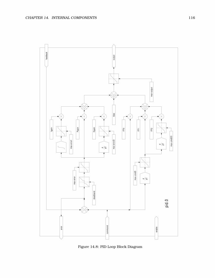
CHAPTER 14. INTERNAL COMPONENTS 116
outp
ut
enab
le
comm
and
feed
back
erro
r
max-
cmdD
D
max-
cmdD
max-
erro
rD
Pgain
FF2
bias
FF0
FF1
Dgain
Igain
max-
erro
rI
max-
outp
ut
max-
erro
r
dead
band
pid.0
d
d
d
dT
dT
dT
Figure 14.8: PID Loop Block Diagram
CHAPTER 14. INTERNAL COMPONENTS 117
14.5.4 Parameters
The PID gains, limits, and other ’tunable’ features of the loop are implemented as parameters.
• (FLOAT) pid.<loopnum>.Pgain – Proportional gain
• (FLOAT) pid.<loopnum>.Igain – Integral gain
• (FLOAT) pid.<loopnum>.Dgain – Derivative gain
• (FLOAT) pid.<loopnum>.bias – Constant offset on output
• (FLOAT) pid.<loopnum>.FF0 – Zeroth order feedforward - output proportional to command(position).
• (FLOAT) pid.<loopnum>.FF1 – First order feedforward - output proportional to derivative ofcommand (velocity).
• (FLOAT) pid.<loopnum>.FF2 – Second order feedforward - output proportional to 2nd deriva-tive of command (acceleration)1.
• (FLOAT) pid.<loopnum>.deadband – Amount of error that will be ignored
• (FLOAT) pid.<loopnum>.maxerror – Limit on error
• (FLOAT) pid.<loopnum>.maxerrorI – Limit on error integrator
• (FLOAT) pid.<loopnum>.maxerrorD – Limit on error derivative
• (FLOAT) pid.<loopnum>.maxcmdD – Limit on command derivative
• (FLOAT) pid.<loopnum>.maxcmdDD – Limit on command 2nd derivative
• (FLOAT) pid.<loopnum>.maxoutput – Limit on output value
All of the max??? limits are implemented such that if the parameter value is zero, there is no limit.
If debug=1 was specified when the component was installed, four additional parameters will beexported:
• (FLOAT) pid.<loopnum>.errorI – Integral of error.
• (FLOAT) pid.<loopnum>.errorD – Derivative of error.
• (FLOAT) pid.<loopnum>.commandD – Derivative of the command.
• (FLOAT) pid.<loopnum>.commandDD – 2nd derivative of the command.
14.5.5 Functions
The component exports one function for each PID loop. This function performs all the calculationsneeded for the loop. Since each loop has its own function, individual loops can be included indifferent threads and execute at different rates.
• (FUNCT) pid.<loopnum>.do_pid_calcs – Performs all calculations for a single PID loop.
If you want to understand the exact algorithm used to compute the output of the PID loop, refer tofigure 14.8, the comments at the beginning of emc2/src/hal/components/pid.c, and of course tothe code itself. The loop calculations are in the C function calc_pid().
1FF2 is not currently implemented, but it will be added. Consider this note a “FIXME” for the code

CHAPTER 14. INTERNAL COMPONENTS 118
14.6 Simulated Encoder
The simulated encoder is exactly that. It produces quadrature pulses with an index pulse, at aspeed controlled by a HAL pin. Mostly useful for testing.
14.6.1 Installing
emc2$ halcmd loadrt sim-encoder num_chan=<number>
<number> is the number of encoders that you want to simulate. If not specified, one encoder will beinstalled. The maximum number is 8 (as defined by MAX_CHAN in sim_encoder.c).
14.6.2 Removing
emc2$ halcmd unloadrt sim-encoder
14.6.3 Pins
• (FLOAT) sim-encoder.<chan-num>.speed – The speed command for the simulated shaft.
• (BIT) sim-encoder.<chan-num>.phase-A – Quadrature output.
• (BIT) sim-encoder.<chan-num>.phase-B – Quadrature output.
• (BIT) sim-encoder.<chan-num>.phase-Z – Index pulse output.
When .speed is positive, .phase-A leads .phase-B.
14.6.4 Parameters
• (U32) sim-encoder.<chan-num>.ppr – Pulses Per Revolution.
• (FLOAT) sim-encoder.<chan-num>.scale – Scale Factor for speed. The default is 1.0, whichmeans that speed is in revolutions per second. Change to 60 for RPM, to 360 for degrees persecond, 6.283185 for radians per seconed, etc.
Note that pulses per revolution is not the same as counts per revolution. A pulse is a completequadrature cycle. Most encoder counters will count four times during one complete cycle.
14.6.5 Functions
The component exports two functions. Each function affects all simulated encoders.
• (FUNCT) sim-encoder.make-pulses – High speed function to generate quadrature pulses (nofloating point).
• (FUNCT) sim-encoder.update-speed – Low speed function to read speed, do scaling, and setup make-pulses.

CHAPTER 14. INTERNAL COMPONENTS 119
14.7 Debounce
Debounce is a realtime component that can filter the glitches created by mechanical switch contacts.It may also be useful in other applications where short pulses are to be rejected.
14.7.1 Installing
emc2$ halcmd loadrt debounce cfg=”<config-string>”
<config-string> is a series of space separated decimal integers. Each number installs a group ofidentical debounce filters, the number determines how many filters are in the group. For example:
emc2$ halcmd loadrt debounce cfg=”1 4 2”
will install three groups of filters. Group 0 contains one filter, group 1 contains four, and group2 contains two filters. The default value for <config-string> is “1” which will install a singlegroup containing a single filter. The maximum number of groups 8 (as defined by MAX_GROUPS indebounce.c). The maximum number of filters in a group is limited only by shared memory space.Each group is completely independent. All filters in a single group are identical, and they are allupdated by the same function at the same time. In the following descriptions, <G> is the groupnumber and <F> is the filter number within the group. The first filter is group 0, filter 0.
14.7.2 Removing
emc2$ halcmd unloadrt debounce
14.7.3 Pins
Each individual filter has two pins.
• (BIT) debounce.<G>.<F>.in – Input of filter <F> in group <G>.
• (BIT) debounce.<G>.<F>.out – Output of filter <F> in group <G>.
14.7.4 Parameters
Each group of filters has one parameter2.
• (S32) debounce.<G>.delay – Filter delay for all filters in group <G>.
The filter delay is in units of thread periods. The minimum delay is zero. The output of a zero delayfilter exactly follows its input - it doesn’t filter anything. As delay increases, longer and longerglitches are rejected. If delay is 4, all glitches less than or equal to four thread periods will berejected.
14.7.5 Functions
Each group of filters has one function, which updates all the filters in that group “simultaneously”.Different groups of filters can be updated from different threads at different periods.
• (FUNCT) debounce.<G> – Updates all filters in group <G>.
2Each individual filter also has an internal state variable. There is a compile time switch that can export that variable asa parameter. This is intended for testing, and simply wastes shared memory under normal circumstances.
CHAPTER 14. INTERNAL COMPONENTS 120
14.8 Blocks
Blocks is a realtime HAL component containing a number of simple functional blocks. They areprimarily intended for testing and other offhand uses, but may prove useful for some EMC configu-rations as well.
14.8.1 Available Blocks
The complete list of available blocks is as follows:
• constant – makes a parameter value available on a pin
• comp – standard 2-input comparator with adjustable hysteresis
• wcomp – window comparator, output true when input is between adjustable upper and lowerlimits
• sum2 – 2-input summer, output = in0 * gain0 + in1 * gain1
• mux2 – 2-input multiplexor, output = in0 if sel is false, output = in1 if sel is true
• mux4 – 4-input multiplexor, output = in<n> based on sel0, sel1
• integ – integrator, input of +1.0 produces an output ramp of +1.0 per second
• ddt – differentiator, input ramp of +1.0 per second produces output of +1.0
• limit1 – first order limiter (limits output)
• limit2 – second order limiter (limits output and 1st derivative)
• limit3 – third order limiter (limits ouput, 1st & 2nd derivative)
• estop – latch for estops or other faults, with reset
• not – logical inverter
• and2 – 2 input logical and
• or2 – 2 input logical or
• scale – gain/offset block (out = in * gain + offset)
• lowpass – lowpass filter (out = last_out * (1 - gain) + in * gain
• match8 – 8 bit binary match detector (with input for cascading)
14.8.2 Installing
emc2$ halcmd loadrt blocks <blockname>=<number>
<blockname> is the name of one of the functional blocks that the component can provide, and<number> is the desired quantity of that block. Multiple name/number pairs may be specified onthe command line to install a variety of different blocks. For example:
emc2$ halcmd loadrt blocks wcomp=2 sum2=1 comp=3
installs two window comparators (wcomp), one two-input summer (sum2), and three standard com-parators (comp).
CHAPTER 14. INTERNAL COMPONENTS 121
14.8.3 Removing
emc2$ halcmd unloadrt blocks
14.8.4 Pins
The various blocks each have their own input and output pins. Each pin begins with the blockname, then the block number, and finally the pin function.
• (FLOAT) constant.<num>.out – Output of constant block, tracks the parameter value.
• (FLOAT) comp.<num>.in0 – Inverting input of 2-input comparator.
• (FLOAT) comp.<num>.in1 – Non-inverting input of 2-input comparator.
• (BIT) comp.<num>.out – Output, true if in1 > in0.
• (FLOAT) wcomp.<num>.in –Input of window comparator.
• (BIT) wcomp.<num>.out – Output, TRUE if min < input < max.
• (FLOAT) sum2.<num>.in0 – First input of 2-input summer.
• (FLOAT) sum2.<num>.in1 – Second input of 2-input summer.
• (FLOAT) sum2.<num>.out – Output, equals in0 * gain0 + in1 * gain1.
• (FLOAT) mux2.<num>.in0 – First input of 2-input multiplexor.
• (FLOAT) mux2.<num>.in1 –Second input of 2-input multiplexor.
• (BIT) mux2.<num>.sel – Control input of 2-input multiplexor.
• (FLOAT) mux2.<num>.out – Output, equals in0 if sel is FALSE, in1 if sel is TRUE.
• (FLOAT) integ.<num>.in – Input of integrator.
• (FLOAT) integ.<num>.out – Output of integrator.
• (FLOAT) ddt.<num>.in – Input of differentiator.
• (FLOAT) ddt.<num>.out – Output of differentiator.
• ... and so on (too many pins to list them all here, but you can easily see them with halcmdshow pin )
14.8.5 Parameters
Some of the blocks have parameters that control and adjust the details of their operation. Like thepin names, they begin with the block name and the block number, then the parameter name.
• (FLOAT) constant.<num>.value – The value to be written to the out pin, default value is 1.0.
• (FLOAT) comp.<num>.hyst – Hystersis for 2-input comparator, default is 0.0.
• (FLOAT) wcomp.<num>.min – Minimum threshold for window comparator, default is -1.0.
• (FLOAT) wcomp.<num>.max – Maximum threshold for window comparator, default is +1.0.
• (FLOAT) sum2.<num>.gain0 – Value by which in0 is multiplied, default is 1.0.
• (FLOAT) sum2.<num>.gain1 – Value by which in1 is multiplied, default is 1.0.
CHAPTER 14. INTERNAL COMPONENTS 122
14.8.6 Functions
Each individual block has its own function. This allows complete control over when each blockexecutes. In general, blocks should execute in the order of signal flow. If the outputs of blocks Aand B are connected to inputs of block C, then the functions for A and B should be executed beforethe function for C. Note that unless these functions are connected to a realtime thread so that theyexecute, the blocks do nothing at all.
• (FUNCT) constant.<num> – Writes parameter value to pin out.
• (FUNCT) comp.<num> – Compares in0 and in1 (with hysteresis), writes result to out.
• (FUNCT) wcomp.<num> – Compares in to min and max, writes result to out.
• (FUNCT) sum2.<num> – Computes out = in0 * gain0 + in1 * gain1.
• (FUNCT) mux2.<num> – If sel is TRUE, writes in1 to out, else writes in0 to out.
• (FUNCT) integ.<num> – Calculates integral of in, writes result to out.
• (FUNCT) constant.<num> – Calculates derivative of in, writes result to out.
CHAPTER 14. INTERNAL COMPONENTS 123
14.9 Siggen
Siggen is a realtime component that generates square, triangle, and sine waves. It is primarily usedfor testing.
14.9.1 Installing
emc2$ halcmd loadrt siggen [num_chan=<chans>]
<chans> is the number of signal generators that you want to install. If numchan is not specified,one signal generator will be installed. The maximum number of generators is 16 (as defined byMAX_CHAN in siggen.c). Each generator is completely independent. In the following descriptions,<chan> is the number of a specific signal generator (the numbers start at 0).
14.9.2 Removing
emc2$ halcmd unloadrt siggen
14.9.3 Pins
Each generator has five output pins.
• (FLOAT) siggen.<chan>.sine – Sine wave output.
• (FLOAT) siggen.<chan>.cosine – Cosine output.
• (FLOAT) siggen.<chan>.sawtooth – Sawtooth output.
• (FLOAT) siggen.<chan>.triangle – Triangle wave output.
• (FLOAT) siggen.<chan>.square – Square wave output.
All five outputs have the same frequency, amplitude, and offset.
In addition to the output pins, there are three control pins:
• (FLOAT) siggen.<chan>.frequency – Sets the frequency in Hertz, default value is 1 Hz.
• (FLOAT) siggen.<chan>.amplitude – Sets the peak amplitude of the output waveforms, de-fault is 1.
• (FLOAT) siggen.<chan>.offset – Sets DC offset of the output waveforms, default is 0.
For example, if siggen.0.amplitude is 1.0 and siggen.0.offset is 0.0, the outputs will swingfrom -1.0 to +1.0. If siggen.0.amplitude is 2.5 and siggen.0.offset is 10.0, then the outputswill swing from 7.5 to 12.5.
14.9.4 Parameters
None. 3
14.9.5 Functions
• (FUNCT) siggen.<chan>.update – Calculates new values for all five outputs.
3Prior to version 2.1, frequency, amplitude, and offset were parameters. They were changed to pins to allow control byother components.

Chapter 15
Hardware Drivers
15.1 Parport
Parport is a driver for the traditional PC parallel port. The port has a total of 17 physical pins. Theoriginal parallel port divided those pins into three groups: data, control, and status. The data groupconsists of 8 output pins, the control group consists of 4 pins, and the status group consists of 5input pins.
In the early 1990’s, the bidirectional parallel port was introduced, which allows the data group tobe used for output or input. The HAL driver supports the bidirectional port, and allows the user toset the data group as either input or output. If configured as output, a port provides a total of 12outputs and 5 inputs. If configured as input, it provides 4 outputs and 13 inputs.
In some parallel ports, the control group pins are open collectors, which may also be driven low byan external gate. On a board with open collector control pins, the “x” mode allows a more flexiblemode with 8 dedicated outputs, 5 dedicated inputs, and 4 open collector pins. In other parallelports, the control group has push-pull drivers and cannot be used as an input.1
No other combinations are supported, and a port cannot be changed from input to output once thedriver is installed. Figure 15.1 shows two block diagrams, one showing the driver when the datagroup is configured for output, and one showing it configured for input.
The parport driver can control up to 8 ports (defined by MAX_PORTS in hal_parport.c). The portsare numbered starting at zero.
15.1.1 Installing
From command line:
emc2$ halcmd loadrt hal_parport cfg="<config-string>"2
1HAL cannot automatically determine if the “x” mode bidirectional pins are actually open collectors (OC). If they are not,they cannot be used as inputs, and attempting to drive them LOW from an external source can damage the hardware.
To determine whether your port has “open collector” pins, load hal_parport in “x” mode, output a HIGH value on the pin.HAL should read the pin as TRUE. Next, insert a 470Ω resistor from one of the control pins to GND. If the resulting voltageon the control pin is close to 0V, and HAL now reads the pin as FALSE, then you have an OC port. If the resulting voltage isfar from 0V, or HAL does not read the pin as FALSE, then your port cannot be used in “x” mode.
The external hardware that drives the control pins should also use open collector gates (e.g., 74LS05). Generally, the -outHAL pins should be set to TRUE when the physical pin is being used as an input.
On some machines, BIOS settings may affect whether “x” mode can be used. “SPP” mode is most most likely to work.2The single quotes around the entire cfg= argument are needed to prevent the shell from misinterpreting the double
quotes around the string, and any spaces or special characters in the string. Single quotes should not be used in a file orfrom the halcmd prompt.
124

CHAPTER 15. HARDWARE DRIVERS 125
From a file or at the halcmd: prompt:
loadrt hal_parport cfg="<config-string>"
The config string consists of a hex port address, followed by an optional direction, repeated foreach port. The direction is “in”, “out”, or “x” and determines the direction of the physical pins 2through 9, and whether to create input HAL pins for the physical control pins. If the direction isnot specified, the data group defaults to output. For example:
loadrt hal_parport cfg="0x278 0x378 in 0x20A0 out"
This example installs drivers for one port at 0x0278, with pins 2-9 as outputs (by default, sinceneither “in” nor “out” was specified), one at 0x0378, with pins 2-9 as inputs, and one at 0x20A0,with pins 2-9 explicitly specified as outputs. Note that you must know the base address of theparallel port to properly configure the driver. For ISA bus ports, this is usually not a problem, sincethe port is almost always at a “well known” address, like 0278 or 0378 which is typically configuredin the system BIOS. The address for a PCI card is usally shown in “lspci -v” in an “I/O ports” line.There is no default address; if <config-string> does not contain at least one address, it is anerror.
15.1.2 Removing
emc2$ halcmd unloadrt hal_parport
15.1.3 Pins
• (BIT) parport.<portnum>.pin-<pinnum>-out – Drives a physical output pin.
• (BIT) parport.<portnum>.pin-<pinnum>-in – Tracks a physical input pin.
• (BIT) parport.<portnum>.pin-<pinnum>-in-not – Tracks a physical input pin, but in-verted.
For each pin, <portnum> is the port number, and <pinnum> is the physical pin number in the 25pin D-shell connector.
For each physical output pin, the driver creates a single HAL pin, for example parport.0.pin-14-out.Pins 1, 14, 16, and 17 are always outputs. Pins 2 through 9 are part of the data group and areoutput pins if the port is defined as an output port. (Output is the default.) These HAL pins controlthe state of the corresponding physical pins.
For each physical input pin, the driver creates two HAL pins, for example parport.0.pin-12-inand parport.0.pin-12-in-not. Pins 10, 11, 12, 13, and 15 are always input pins. Pins 2 through9 are input pins only if the port is defined as an input port. The -in HAL pin is TRUE if the physicalpin is high, and FALSE if the physical pin is low. The -in-not HAL pin is inverted – it is FALSEif the physical pin is high. By connecting a signal to one or the other, the user can determine thestate of the input.
15.1.4 Parameters
• (BIT) parport.<portnum>.pin-<pinnum>-out-invert – Inverts an output pin.
The -invert parameter determines whether an output pin is active high or active low. If -invertis FALSE, setting the HAL -out pin TRUE drives the physical pin high, and FALSE drives it low. If-invert is TRUE, then setting the HAL -out pin TRUE will drive the physical pin low.

CHAPTER 15. HARDWARE DRIVERS 126
pin-8
-in-n
otpin
-8-in
pin-7
-in-n
otpin
-7-in
pin-6
-in-n
otpin
-6-in
pin-5
-in-n
otpin
-5-in
pin-4
-in-n
otpin
-4-in
pin-3
-in-n
otpin
-3-in
pin-2
-in-n
otpin
-2-in
pin-9
-in-n
otpin
-9-in
pin-1
5-in-
not
pin-1
5-in
pin-1
3-in-
not
pin-1
3-in
pin-1
2-in-
not
pin-1
2-in
pin-1
1-in-
not
pin-1
1-in
pin-1
0-in-
not
pin-1
0-in
pin-1
7-ou
t-inv
ert
pin-1
7-ou
t
pin-1
6-ou
t-inv
ert
pin-1
6-ou
t
pin-1
4-ou
t-inv
ert
pin-1
4-ou
t
pin-1
-out
-inve
rtpin
-1-o
ut
pin-1
0-in-
not
pin-1
0-in
pin-1
1-in-
not
pin-1
1-in
pin-1
2-in-
not
pin-1
2-in
pin-1
3-in-
not
pin-1
3-in
pin-1
5-in-
not
pin-1
5-in
pin-8
-out
-inve
rtpin
-8-o
ut
pin-7
-out
-inve
rtpin
-7-o
ut
pin-6
-out
-inve
rtpin
-6-o
ut
pin-5
-out
-inve
rtpin
-5-o
ut
pin-4
-out
-inve
rtpin
-4-o
ut
pin-3
-out
-inve
rtpin
-3-o
ut
pin-2
-out
-inve
rtpin
-2-o
ut
pin-9
-out
-inve
rtpin
-9-o
ut
pin-1
7-ou
t-inv
ert
pin-1
7-ou
t
pin-1
6-ou
t-inv
ert
pin-1
6-ou
t
pin-1
4-ou
t-inv
ert
pin-1
4-ou
t
pin-1
-out
-inve
rtpin
-1-o
ut
2525
1313
2424
1212
1111
1010
99
88
77
66
55
44
33
22
11
2323
2222
2121
2020
1919
1818
1717
1616
1515
1414
parp
ort.0
parp
ort.0
conf
igure
d as
inpu
tco
nfigu
red
as o
utpu
t
Figure 15.1: Parport Block Diagram
CHAPTER 15. HARDWARE DRIVERS 127
15.1.5 Functions
• (FUNCT) parport.<portnum>.read– Reads physical input pins of port <portnum> and up-dates HAL -in and -in-not pins.
• (FUNCT) parport.read-all – Reads physical input pins of all ports and updates HAL -inand -in-not pins.
• (FUNCT) parport.<portnum>.write – Reads HAL -out pins of port <portnum> and updatesthat port’s physical output pins.
• (FUNCT) parport.write-all – Reads HAL -out pins of all ports and updates all physicaloutput pins.
The individual functions are provided for situations where one port needs to be updated in a veryfast thread, but other ports can be updated in a slower thread to save CPU time. It is probably nota good idea to use both an -all function and an individual function at the same time.
15.1.6 Common problems
If loading the module reports
insmod: error inserting ’/home/jepler/emc2/rtlib/hal_parport.ko’:-1 Device or resource busy
then ensure that the standard kernel module parport_pc is not loaded and that no other device inthe system has claimed the I/O ports.
If the module loads but does not appear to function, then the port address is incorrect or theprobe_parport module is required.
15.2 probe_parport
In modern PCs, the parallel port may require plug and play (PNP) configuration before it can beused. The probe_parport module performs configuration of any PNP ports present, and should beloaded before hal_parport. On machines without PNP ports, it cannot be loaded.
15.2.1 Installing
loadrt probe_parportloadrt hal_parport ...
If the Linux kernel prints a message similar to
parport: PnPBIOS parport detected.
when the parport_pc module is loaded (sudo modprobe -a parport_pc) then use of this moduleis probably required
15.3 AX5214H
The Axiom Measurement & Control AX5214H is a 48 channel digital I/O board. It plugs into an ISAbus, and resembles a pair of 8255 chips.3
3In fact it may be a pair of 8255 chips, but I’m not sure. If/when someone starts a driver for an 8255 they should look atthe ax5214 code, much of the work is already done.
CHAPTER 15. HARDWARE DRIVERS 128
15.3.1 Installing
From command line:
emc2$ halcmd loadrt hal_ax5214h ’cfg="<config-string>"’4
From a file:
loadrt hal_ax5214h cfg="<config-string>"
The config string consists of a hex port address, followed by an 8 character string of “I” and “O”which sets groups of pins as inputs and outputs. The first two character set the direction of thefirst two 8 bit blocks of pins (0-7 and 8-15). The next two set blocks of 4 pins (16-19 and 20-23). Thepattern then repeats, two more blocks of 8 bits (24-31 and 32-39) and two blocks of 4 bits (40-43and 44-47). If more than one board is installed, the data for the second board follows the first. Asan example, the string "0x220 IIIOIIOO 0x300 OIOOIOIO" installs drivers for two boards. Thefirst board is at address 0x220, and has 36 inputs (0-19 and 24-39) and 12 outputs (20-23 and40-47). The second board is at address 0x300, and has 20 inputs (8-15, 24-31, and 40-43) and 28outputs (0-7. 16-23, 32-39, and 44-47).
15.3.2 Removing
emc2$ halcmd unloadrt hal_ax5214
15.3.3 Pins
• (BIT) ax5214.<boardnum>.out-<pinnum> – Drives a physical output pin.
• (BIT) ax5214.<boardnum>.in-<pinnum> – Tracks a physical input pin.
• (BIT) ax5214.<boardnum>.in-<pinnum>-not – Tracks a physical input pin, inverted.
For each pin, <boardnum> is the board number (starts at zero), and <pinnum> is the I/O channelnumber (0 to 47).
Note that the driver assumes active LOW signals. This is so that modules such as OPTO-22 willwork correctly (TRUE means output ON, or input energized). If the signals are being used directlywithout buffering or isolation the inversion needs to be accounted for. The in- HAL pin is TRUE ifthe physical pin is low (OPTO-22 module energized), and FALSE if the physical pin is high (OPTO-22 module off). The in-<pinnum>-not HAL pin is inverted – it is FALSE if the physical pin is low(OPTO-22 module energized). By connecting a signal to one or the other, the user can determinethe state of the input.
15.3.4 Parameters
• (BIT) ax5214.<boardnum>.out-<pinnum>-invert – Inverts an output pin.
The -invert parameter determines whether an output pin is active high or active low. If -invert isFALSE, setting the HAL out- pin TRUE drives the physical pin low, turning ON an attached OPTO-22 module, and FALSE drives it high, turning OFF the OPTO-22 module. If -invert is TRUE, thensetting the HAL out- pin TRUE will drive the physical pin high and turn the module OFF.
4The single quotes around the entire cfg= argument are needed to prevent the shell from misinterpreting the doublequotes around the string, and any spaces or special characters in the string. Single quotes should not be used in a file orfrom the halcmd prompt.

CHAPTER 15. HARDWARE DRIVERS 129
15.3.5 Functions
• (FUNCT) ax5214.<boardnum>.read – Reads all digital inputs on one board.
• (FUNCT) ax5214.<boardnum>.write – Writes all digital outputs on one board.
15.4 Servo-To-Go
The Servo-To-Go is one of the first PC motion control cards5 supported by EMC. It is an ISA cardand it exists in different flavours (all supported by this driver). The board includes up to 8 channelsof quadrature encoder input, 8 channels of analog input and output, 32 bits digital I/O, an intervaltimer with interrupt and a watchdog.
15.4.1 Installing:
emc2$ halcmd loadrt hal_stg [base=<address>] [num_chan=<nr>] \[dio="<dio-string>"] [model=<model>]
The base address field is optional; if it’s not provided the driver attempts to autodetect the board.The num_chan field is used to specify the number of channels available on the card, if not used the8 axis version is assumed. The digital inputs/outputs configuration is determined by a config stringpassed to insmod when loading the module. The format consists of a four character string that setsthe direction of each group of pins. Each character of the direction string is either "I" or "O". Thefirst character sets the direction of port A (Port A - DIO.0-7), the next sets port B (Port B - DIO.8-15),the next sets port C (Port C - DIO.16-23), and the fourth sets port D (Port D - DIO.24-31). The modelfield can be used in case the driver doesn’t autodetect the right card version6. For example:
emc2$ halcmd loadrt hal_stg base=0x300 num_chan=4 dio="IOIO"
This example installs the stg driver for a card found at the base address of 0x300, 4 channels ofencoder feedback, DAC’s and ADC’s, along with 32 bits of I/O configured like this: the first 8 (PortA) configured as Input, the next 8 (Port B) configured as Output, the next 8 (Port C) configured asInput, and the last 8 (Port D) configured as Output
emc2$ halcmd loadrt hal_stg
This example installs the driver and attempts to autodetect the board address and board model, itinstalls 8 axes by default along with a standard I/O setup: Port A & B configured as Input, Port C& D configured as Output.
15.4.2 Removing
emc2$ halcmd unloadrt hal_stg
5a motion control card usually is a board containing devices to control one or more axes (the control devices are usuallyDAC’s to set an analog voltage, encoder counting chips for feedback, etc.)
6hint: after starting up the driver, ’dmesg’ can be consulted for messages relevant to the driver (e.g. autodetected versionnumber and base address)
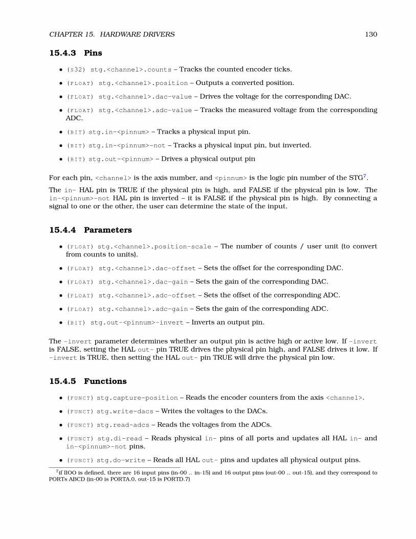
CHAPTER 15. HARDWARE DRIVERS 130
15.4.3 Pins
• (S32) stg.<channel>.counts – Tracks the counted encoder ticks.
• (FLOAT) stg.<channel>.position – Outputs a converted position.
• (FLOAT) stg.<channel>.dac-value – Drives the voltage for the corresponding DAC.
• (FLOAT) stg.<channel>.adc-value – Tracks the measured voltage from the correspondingADC.
• (BIT) stg.in-<pinnum> – Tracks a physical input pin.
• (BIT) stg.in-<pinnum>-not – Tracks a physical input pin, but inverted.
• (BIT) stg.out-<pinnum> – Drives a physical output pin
For each pin, <channel> is the axis number, and <pinnum> is the logic pin number of the STG7.
The in- HAL pin is TRUE if the physical pin is high, and FALSE if the physical pin is low. Thein-<pinnum>-not HAL pin is inverted – it is FALSE if the physical pin is high. By connecting asignal to one or the other, the user can determine the state of the input.
15.4.4 Parameters
• (FLOAT) stg.<channel>.position-scale – The number of counts / user unit (to convertfrom counts to units).
• (FLOAT) stg.<channel>.dac-offset – Sets the offset for the corresponding DAC.
• (FLOAT) stg.<channel>.dac-gain – Sets the gain of the corresponding DAC.
• (FLOAT) stg.<channel>.adc-offset – Sets the offset of the corresponding ADC.
• (FLOAT) stg.<channel>.adc-gain – Sets the gain of the corresponding ADC.
• (BIT) stg.out-<pinnum>-invert – Inverts an output pin.
The -invert parameter determines whether an output pin is active high or active low. If -invertis FALSE, setting the HAL out- pin TRUE drives the physical pin high, and FALSE drives it low. If-invert is TRUE, then setting the HAL out- pin TRUE will drive the physical pin low.
15.4.5 Functions
• (FUNCT) stg.capture-position – Reads the encoder counters from the axis <channel>.
• (FUNCT) stg.write-dacs – Writes the voltages to the DACs.
• (FUNCT) stg.read-adcs – Reads the voltages from the ADCs.
• (FUNCT) stg.di-read – Reads physical in- pins of all ports and updates all HAL in- andin-<pinnum>-not pins.
• (FUNCT) stg.do-write – Reads all HAL out- pins and updates all physical output pins.
7if IIOO is defined, there are 16 input pins (in-00 .. in-15) and 16 output pins (out-00 .. out-15), and they correspond toPORTs ABCD (in-00 is PORTA.0, out-15 is PORTD.7)

CHAPTER 15. HARDWARE DRIVERS 131
15.5 Mesa Electronics m5i20 “Anything I/O Card”
The Mesa Electronics m5i20 card consists of an FPGA that can be loaded with a wide variety ofconfigurations, and has 72 pins that leave the PC. The assignment of the pins depends on theFPGA configuration. Currently there is a HAL driver for the “4 axis host based motion control”configuration, and this FPGA configurations is also provided with EMC2. It provides 8 encodercounters, 4 PWM outputs (normally used as DACs) and up to 48 digital I/O channels, 32 inputsand 16 outputs.8
Installing:
emc2$ halcmd loadrt hal_m5i20 [loadFpga=1|0] [dacRate=<rate>]
If loadFpga is 1 (the default) the driver will load the FPGA configuration on startup. If it is 0, thedriver assumes the configuration is already loaded. dacRate sets the carrier frequency for the PWMoutputs, in Hz. The default is 32000, for 32KHz PWM.9 The driver prints some usefull debuggingmessage to the kernel log, which can be viewed with dmesg.
15.5.1 Removing
emc2$ halcmd unloadrt hal_m5i20
15.5.2 Pins
In the following pins, parameters, and functions, <board> is the board ID. According to the namingconventions the first board should always have an ID of zero, however this driver uses the PCIboard ID, so it may be non-zero even if there is only one board. The driver attempts to emulate the“canonical encoder”, however there are some differences.10
• (S32) m5i20.<board>.enc-<channel>-count – Encoder position, in counts.
• (FLOAT) m5i20.<board>.enc-<channel>-position – Encoder position, in user units.
• (BIT) m5i20.<board>.enc-<channel>-index – Current status of index pulse input
• (BIT) m5i20.<board>.enc-<channel>-index-enable – Bidirectional - if TRUE, counter willreset on next index pulse, and index-enable will be cleared
• (BIT) m5i20.<board>.enc-<channel>-reset-count – Bidirectional - if TRUE, counter willreset immediately, and reset-count will be cleared.
• (BIT) m5i20.<board>.dac-<channel>-enable – Enables DAC if true. DAC outputs zerovolts if false?
• (FLOAT) m5i20.<board>.dac-<channel>-value – Analog output value for PWM “DAC” (inuser units, see -scale and -offset)
• (BIT) m5i20.<board>.in-<channel> – State of digital input pin, see canonical digital input.
8Ideally the encoders, “DACs”, and digital I/O would comply with the canonical interfaces defined earlier, but they don’t.Fixing that is on the things-to-do list.
9I don’t know what the maximum (and minimum, if any) PWM frequency is, it should be documented here. Also, this isthe kind of thing that ideally is controlled by a HAL parameter, rather than being set when the driver is initially loaded. Idon’t know if that is possible, it depends on the hardware and I don’t have the neccessary information.
10Versions 2.1.6 and earlier had a significantly different encoder interface, and had bugs in the indexing code. Normalmotion control worked, but homing to index, threading, and rigid tapping did not, since all of those features require theindex pulse to work properly. This documentation is for versions 2.1.7 and later.

CHAPTER 15. HARDWARE DRIVERS 132
• (BIT) m5i20.<board>.in-<channel>-not – Inverted state of digital input pin, see canonicaldigital input.
• (BIT) m5i20.<board>.out-<channel> – Value to be written to digital output, see canonicaldigital output.
• (BIT) m5i20.<board>.estop-in – Dedicated estop input, more details needed.
• (BIT) m5i20.<board>.estop-in-not – Inverted state of dedicated estop input.
• (BIT) m5i20.<board>.watchdog-reset – Bidirectional, - Set TRUE to reset watchdog once,is automatically cleared. If bit value 16 is set in watchdog-control then this value is notused, and the hardware watchdog is cleared every time the dac-write function is executed.
15.5.3 Parameters
• (FLOAT) m5i20.<board>.enc-<channel>-scale – The number of counts / user unit (to con-vert from counts to units).
• (FLOAT) m5i20.<board>.dac-<channel>-offset – Sets the DAC offset.
• (FLOAT) m5i20.<board>.dac-<channel>-gain – Sets the DAC gain (scaling).
• (BIT) m5i20.<board>.dac-<channel>-interlaced – Sets the DAC to interlaced mode. Usethis mode if you are filtering the PWM to generate an anaolg voltage.11
• (BIT) m5i20.<board>.out-<channel>-invert – Inverts a digital output, see canonical dig-ital output.
• (U32) m5i20.<board>.watchdog-control – Configures the watchdog. The value may be abitwise OR of the following values:Bit # Value Meaning
0 1 Watchdog is enabled1 2 Watchdog is automatically reset by DAC writes (the HAL dac-write function)
Typically, the useful values are 0 (watchdog disabled) or 3 (watchdog enabled, cleared bydac-write).
• (U32) m5i20.<board>.led-view – Maps some of the I/O to onboard LEDs. See table below.
15.5.4 Functions
• (FUNCT) m5i20.<board>.encoder-read – Reads all encoder counters.
• (FUNCT) m5i20.<board>.digital-in-read – Reads digital inputs.
• (FUNCT) m5i20.<board>.dac-write – Writes the voltages (PWM duty cycles) to the “DACs”.
• (FUNCT) m5i20.<board>.digital-out-write – Writes digital outputs.
• (FUNCT) m5i20.<board>.misc-update – Writes watchdog timer configuration to hardware.Resets watchdog timer. Updates E-stop pin (more info needed). Updates onboard LEDs.
15.5.5 Connector pinout
The Hostmot-4 FPGA configuration has the following pinout. There are three 50-pin ribbon cableconnectors on the card: P2, P3, and P4. There are also 8 status LEDs.
11With normal 10 bit PWM, 50% duty cycle would be 512 cycles on and 512 cycles off = ca 30 kHz with 33 MHz referencecounter. With fully interleaved PWM this would be 1 cycle on, 1 cycle off for 1024 cycles (16.66 MHz if the PWM referencecounter runs at 33 MHz) = much easier to filter. The 5I20 configuration interlace is somewhat between non and fullyinterlaced (to make it easy to filter but not have as many transistions as fully interleaved).

CHAPTER 15. HARDWARE DRIVERS 133
15.5.5.1 Connecor P2
m5i20 card connector P2 Function/HAL-pin1 enc-01 A input3 enc-01 B input5 enc-00 A input7 enc-00 B input9 enc-01 index input11 enc-00 index input13 dac-01 output15 dac-00 output17 DIR output for dac-0119 DIR output for dac-0021 dac-01-enable output23 dac-00-enable output25 enc-03 B input27 enc-03 A input29 enc-02 B input31 enc-02 A input33 enc-03 index input35 enc-02 index input37 dac-03 output39 dac-02 output41 DIR output for dac-0343 DIR output for dac-0245 dac-03-enable output47 dac-02-enable output49 Power +5 V (or +3.3V ?)
all even pins Ground
15.5.5.2 Connector P3
Encoder counters 4 - 7 work simultaneously with in-00 to in-11.
If you are using in-00 to in-11 as general purpose IO then reading enc-<4-7> will produce somerandom junk number.
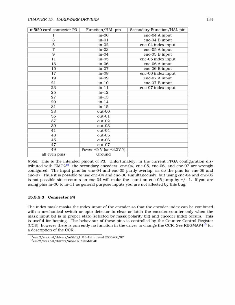
CHAPTER 15. HARDWARE DRIVERS 134
m5i20 card connector P3 Function/HAL-pin Secondary Function/HAL-pin1 in-00 enc-04 A input3 in-01 enc-04 B input5 in-02 enc-04 index input7 in-03 enc-05 A input9 in-04 enc-05 B input11 in-05 enc-05 index input13 in-06 enc-06 A input15 in-07 enc-06 B input17 in-08 enc-06 index input19 in-09 enc-07 A input21 in-10 enc-07 B input23 in-11 enc-07 index input25 in-1227 in-1329 in-1431 in-1533 out-0035 out-0137 out-0239 out-0341 out-0443 out-0545 out-0647 out-0749 Power +5 V (or +3.3V ?)
all even pins Ground
Note!: This is the intended pinout of P3. Unfortunately, in the current FPGA configuration dis-tributed with EMC212, the secondary encoders, enc-04, enc-05, enc-06, and enc-07 are wronglyconfigured. The input pins for enc-04 and enc-05 partly overlap, as do the pins for enc-06 andenc-07. Thus it is possible to use enc-04 and enc-06 simultaneously, but using enc-04 and enc-05is not possible since counts on enc-04 will make the count on enc-05 jump by +/- 1. If you areusing pins in-00 to in-11 as general purpose inputs you are not affected by this bug.
15.5.5.3 Connector P4
The index mask masks the index input of the encoder so that the encoder index can be combinedwith a mechanical switch or opto detector to clear or latch the encoder counter only when themask input bit is in proper state (selected by mask polarity bit) and encoder index occurs. Thisis useful for homing. The behaviour of these pins is controlled by the Counter Control Register(CCR), however there is currently no function in the driver to change the CCR. See REGMAP413 fora description of the CCR.
12emc2/src/hal/drivers/m5i20_HM5-4E.h dated 2005/06/0713emc2/src/hal/drivers/m5i20/REGMAP4E

CHAPTER 15. HARDWARE DRIVERS 135
m5i20 card connector P4 Function/HAL-pin Secondary Function/HAL-pin1 in-16 enc-00 index mask3 in-17 enc-01 index mask5 in-18 enc-02 index mask7 in-19 enc-03 index mask9 in-2011 in-2113 in-2215 in-2317 in-24 enc-04 index mask19 in-25 enc-05 index mask21 in-26 enc-06 index mask23 in-27 enc-07 index mask25 in-2827 in-2929 in-3031 in-3133 out-0835 out-0937 out-1039 out-1141 out-1243 out-1345 out-1447 out-1549 Power +5 V (or +3.3V ?)
all even pins Ground
15.5.5.4 LEDs
The status LEDs will monitor one motion channel set by the m5i20.<board>.led-view parameter.A call to m5i20.<board>.misc-update is required to update the LEDs.
LED name OutputLED0 IRQLatch ?LED1 enc-<channel> ALED2 enc-<channel> BLED3 enc-<channel> indexLED4 dac-<channel> DIRLED5 dac-<channel>LED6 dac-<channel>-enableLED7 watchdog timeout ?
15.6 Vital Systems Motenc-100 and Motenc-LITE
The Vital Systems Motenc-100 and Motenc-LITE are 8- and 4-channel servo control boards. TheMotenc-100 provides 8 quadrature encoder counters, 8 analog inputs, 8 analog outputs, 64 (68?)digital inputs, and 32 digital outputs. The Motenc-LITE has only 4 encoder counters, 32 digitalinputs and 16 digital outputs, but it still has 8 analog inputs and 8 analog outputs. The driverautomatically identifies the installed board and exports the appropriate HAL objects.14
Installing:14Ideally the encoders, DACs, ADCs, and digital I/O would comply with the canonical interfaces defined earlier, but they
don’t. Fixing that is on the things-to-do list.

CHAPTER 15. HARDWARE DRIVERS 136
emc2$ halcmd loadrt hal_motenc
During loading (or attempted loading) the driver prints some usefull debugging message to thekernel log, which can be viewed with dmesg.
15.6.1 Removing
emc2$ halcmd unloadrt hal_motenc
15.6.2 Pins
In the following pins, parameters, and functions, <board> is the board ID. According to the namingconventions the first board should always have an ID of zero. However this driver sets the ID basedon a pair of jumpers on the baord, so it may be non-zero even if there is only one board.
• (S32) motenc.<board>.enc-<channel>-count – Encoder position, in counts.
• (FLOAT) motenc.<board>.enc-<channel>-position – Encoder position, in user units.
• (BIT) motenc.<board>.enc-<channel>-index – Current status of index pulse input.
• (BIT) motenc.<board>.enc-<channel>-idx-latch – Driver sets this pin true when it latchesan index pulse (enabled by latch-index). Cleared by clearing latch-index.
• (BIT) motenc.<board>.enc-<channel>-latch-index – If this pin is true, the driver willreset the counter on the next index pulse.
• (BIT) motenc.<board>.enc-<channel>-reset-count – If this pin is true, the counter willimmediately be reset to zero, and the pin will be cleared.
• (FLOAT) motenc.<board>.dac-<channel>-value – Analog output value for DAC (in userunits, see -gain and -offset)
• (FLOAT) motenc.<board>.adc-<channel>-value – Analog input value read by ADC (in userunits, see -gain and -offset)
• (BIT) motenc.<board>.in-<channel> – State of digital input pin, see canonical digital input.
• (BIT) motenc.<board>.in-<channel>-not – Inverted state of digital input pin, see canonicaldigital input.
• (BIT) motenc.<board>.out-<channel> – Value to be written to digital output, seen canonicaldigital output.
• (BIT) motenc.<board>.estop-in – Dedicated estop input, more details needed.
• (BIT) motenc.<board>.estop-in-not – Inverted state of dedicated estop input.
• (BIT) motenc.<board>.watchdog-reset – Bidirectional, - Set TRUE to reset watchdog once,is automatically cleared.

CHAPTER 15. HARDWARE DRIVERS 137
15.6.3 Parameters
• (FLOAT) motenc.<board>.enc-<channel>-scale – The number of counts / user unit (toconvert from counts to units).
• (FLOAT) motenc.<board>.dac-<channel>-offset – Sets the DAC offset.
• (FLOAT) motenc.<board>.dac-<channel>-gain – Sets the DAC gain (scaling).
• (FLOAT) motenc.<board>.adc-<channel>-offset – Sets the ADC offset.
• (FLOAT) motenc.<board>.adc-<channel>-gain – Sets the ADC gain (scaling).
• (BIT) motenc.<board>.out-<channel>-invert – Inverts a digital output, see canonical dig-ital output.
• (U32) motenc.<board>.watchdog-control – Configures the watchdog. The value may be abitwise OR of the following values:Bit # Value Meaning
0 1 Timeout is 16ms if set, 8ms if unset2 4 Watchdog is enabled4 16 Watchdog is automatically reset by DAC writes (the HAL dac-write function)
Typically, the useful values are 0 (watchdog disabled) or 20 (8ms watchdog enabled, clearedby dac-write).
• (U32) motenc.<board>.led-view – Maps some of the I/O to onboard LEDs?
15.6.4 Functions
• (FUNCT) motenc.<board>.encoder-read – Reads all encoder counters.
• (FUNCT) motenc.<board>.adc-read – Reads the analog-to-digital converters.
• (FUNCT) motenc.<board>.digital-in-read – Reads digital inputs.
• (FUNCT) motenc.<board>.dac-write – Writes the voltages to the DACs.
• (FUNCT) motenc.<board>.digital-out-write – Writes digital outputs.
• (FUNCT) motenc.<board>.misc-update – Updates misc stuff.
15.7 Pico Systems PPMC (Parallel Port Motion Control)
Pico Systems has a family of boards for doing servo, stepper, and pwm control. The boards connectto the PC through a parallel port working in EPP mode. Although most users connect one boardto a parallel port, in theory any mix of up to 8 or 16 boards can be used on a single parport. Onedriver serves all types of boards. The final mix of I/O depends on the connected board(s). The driverdoesn’t distinguish between boards, it simply numbers I/O channels (encoders, etc) starting from 0on the first card.
Installing:
emc2$ halcmd loadrt hal_ppmc port_addr=<addr1>[,<addr2>[,<addr3>]]
The port_addr parameter tells the driver what parallel port(s) to check. By default, <addr1> is0x0378, and <addr2> and <addr3> are not used.The driver searches the entire address space ofthe enhanced parallel port(s) at port_addr, looking for any board(s) in the PPMC family. It thenexports HAL pins for whatever it finds. During loading (or attempted loading) the driver prints someusefull debugging message to the kernel log, which can be viewed with dmesg.
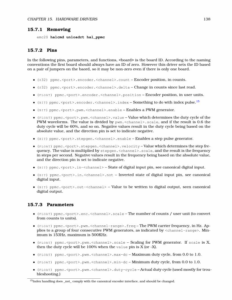
CHAPTER 15. HARDWARE DRIVERS 138
15.7.1 Removing
emc2$ halcmd unloadrt hal_ppmc
15.7.2 Pins
In the following pins, parameters, and functions, <board> is the board ID. According to the namingconventions the first board should always have an ID of zero. However this driver sets the ID basedon a pair of jumpers on the baord, so it may be non-zero even if there is only one board.
• (S32) ppmc.<port>.encoder.<channel>.count – Encoder position, in counts.
• (S32) ppmc.<port>.encoder.<channel>.delta – Change in counts since last read.
• (FLOAT) ppmc.<port>.encoder.<channel>.position – Encoder position, in user units.
• (BIT) ppmc.<port>.encoder.<channel>.index – Something to do with index pulse.15
• (BIT) ppmc.<port>.pwm.<channel>.enable – Enables a PWM generator.
• (FLOAT) ppmc.<port>.pwm.<channel>.value – Value which determines the duty cycle of thePWM waveforms. The value is divided by pwm.<channel>.scale, and if the result is 0.6 theduty cycle will be 60%, and so on. Negative values result in the duty cycle being based on theabsolute value, and the direction pin is set to indicate negative.
• (BIT) ppmc.<port>.stepgen.<channel>.enable – Enables a step pulse generator.
• (FLOAT) ppmc.<port>.stepgen.<channel>.velocity – Value which determines the step fre-quency. The value is multiplied by stepgen.<channel>.scale, and the result is the frequencyin steps per second. Negative values result in the frequency being based on the absolute value,and the direction pin is set to indicate negative.
• (BIT) ppmc.<port>.in-<channel> – State of digital input pin, see canonical digital input.
• (BIT) ppmc.<port>.in.<channel>.not – Inverted state of digital input pin, see canonicaldigital input.
• (BIT) ppmc.<port>.out-<channel> – Value to be written to digital output, seen canonicaldigital output.
15.7.3 Parameters
• (FLOAT) ppmc.<port>.enc.<channel>.scale – The number of counts / user unit (to convertfrom counts to units).
• (FLOAT) ppmc.<port>.pwm.<channel-range>.freq – The PWM carrier frequency, in Hz. Ap-plies to a group of four consecutive PWM generators, as indicated by <channel-range>. Min-imum is 153Hz, maximum is 500KHz.
• (FLOAT) ppmc.<port>.pwm.<channel>.scale – Scaling for PWM generator. If scale is X,then the duty cycle will be 100% when the value pin is X (or -X).
• (FLOAT) ppmc.<port>.pwm.<channel>.max-dc – Maximum duty cycle, from 0.0 to 1.0.
• (FLOAT) ppmc.<port>.pwm.<channel>.min-dc – Minimum duty cycle, from 0.0 to 1.0.
• (FLOAT) ppmc.<port>.pwm.<channel>.duty-cycle – Actual duty cycle (used mostly for trou-bleshooting.)
15Index handling does _not_ comply with the canonical encoder interface, and should be changed.

CHAPTER 15. HARDWARE DRIVERS 139
• (BIT) ppmc.<port>.pwm.<channel>.bootstrap – If true, the PWM generator will generate ashort sequence of pulses of both polarities when it is enabled, to charge the bootstrap capaca-tors used on some MOSFET gate drivers.
• (U32) ppmc.<port>.stepgen.<channel-range>.setup-time – Sets minimum time betweendirection change and step pulse, in units of 100nS. Applies to a group fof four consecutive PWMgenerators, as indicated by <channel-range>.
• (U32) ppmc.<port>.stepgen.<channel-range>.pulse-width – Sets width of step pulses,in units of 100nS. Applies to a group fof four consecutive PWM generators, as indicated by<channel-range>.
• (U32) ppmc.<port>.stepgen.<channel-range>.pulse-space-min – Sets minimum timebetween pulses, in units of 100nS. The maximum step rate is 1/( 100nS * ( pulse-width+ pulse-space-min )). Applies to a group fof four consecutive PWM generators, as indicatedby <channel-range>.
• (FLOAT) ppmc.<port>.stepgen.<channel>.scale – Scaling for step pulse generator. Thestep frequency in Hz is the absolute value of velocity * scale.
• (FLOAT) ppmc.<port>.stepgen.<channel>.max-vel – The maximum value for velocity.Commands greater than max-vel will be clamped. Also applies to negative values. (The abso-lute value is clamped.)
• (FLOAT) ppmc.<port>.stepgen.<channel>.frequency – Actual step pulse frequency in Hz(used mostly for troubleshooting.)
• (BIT) ppmc.<port>.out.<channel>.invert – Inverts a digital output, see canonical digitaloutput.
15.7.4 Functions
• (FUNCT) ppmc.<port>.read – Reads all inputs (digital inputs and encoder counters) on oneport.
• (FUNCT) ppmc.<port>.write – Writes all outputs (digital outputs, stepgens, PWMs) on oneport.
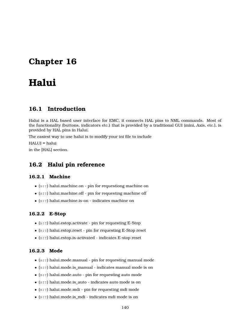
Chapter 16
Halui
16.1 Introduction
Halui is a HAL based user interface for EMC, it connects HAL pins to NML commands. Most ofthe functionality (buttons, indicators etc.) that is provided by a traditional GUI (mini, Axis, etc.), isprovided by HAL pins in Halui.
The easiest way to use halui is to modify your ini file to include
HALUI = halui
in the [HAL] section.
16.2 Halui pin reference
16.2.1 Machine
• (BIT) halui.machine.on - pin for requestiong machine on
• (BIT) halui.machine.off - pin for requesting machine off
• (BIT) halui.machine.is-on - indicates machine on
16.2.2 E-Stop
• (BIT) halui.estop.activate - pin for requesting E-Stop
• (BIT) halui.estop.reset - pin for requesting E-Stop reset
• (BIT) halui.estop.is-activated - indicates E-stop reset
16.2.3 Mode
• (BIT) halui.mode.manual - pin for requesting manual mode
• (BIT) halui.mode.is_manual - indicates manual mode is on
• (BIT) halui.mode.auto - pin for requesting auto mode
• (BIT) halui.mode.is_auto - indicates auto mode is on
• (BIT) halui.mode.mdi - pin for requesting mdi mode
• (BIT) halui.mode.is_mdi - indicates mdi mode is on
140

CHAPTER 16. HALUI 141
16.2.4 Mist, Flood, Lube
• (BIT) halui.mist.on - pin for requesting mist on
• (BIT) halui.mist.is-on - indicates mist is on
• (BIT) halui.flood.on - pin for requesting flood on
• (BIT) halui.flood.is-on - indicates flood is on
• (BIT) halui.lube.on - pin for requesting lube on
• (BIT) halui.lube.is-on - indicates lube is on
16.2.5 Spindle
• (BIT) halui.spindle.start
• (BIT) halui.spindle.stop
• (BIT) halui.spindle.forward
• (BIT) halui.spindle.reverse
• (BIT) halui.spindle.increase
• (BIT) halui.spindle.decrease
• (BIT) halui.spindle.brake-on - pin for activating spindle-brake
• (BIT) halui.spindle.brake-off - pin for deactivating spindle/brake
• (BIT) halui.spindle.brake-is-on - indicates brake is on
16.2.6 Joints
<channel> is a number between 0 and 7 and ’selected’.
• (BIT) halui.joint.<channel>.home - pin for homing the specific joint
• (BIT) halui.joint.<channel>.on-min-limit-soft - status pin telling joint is at the negative softwarelimit
• (BIT) halui.joint.<channel>.on-max-limit-soft - status pin telling joint is at the positive softwarelimit
• (BIT) halui.joint.<channel>.on-min-limit-hard - status pin telling joint is on the negative hard-ware limit switch
• (BIT) halui.joint.<channel>.on-max-limit-hard - status pin telling joint is on the positive hard-ware limit switch
• (BIT) halui.joint.<channel>.fault - status pin telling the joint has a fault
• (BIT) halui.joint.<channel>.homed - status pin telling that the joint is homed

CHAPTER 16. HALUI 142
16.2.7 Jogging
<channel> is a number between 0 and 7 and ’selected’.
• (FLOAT) halui.jog.speed - set jog speed
• (BIT) halui.jog.<channel>.minus - jog in negative direction
• (BIT) halui.jog.<channel>.plus - jog in positive direction
16.2.8 Selecting a joint
• (U32) halui.joint.select - select joint (0..7) - internal halui
• (U32) halui.joint.selected - selected joint (0..7) - internal halui
• (BIT) halui.joint.x.select bit - pins for selecting a joint - internal halui
• (BIT) halui.joint.x.is-selected bit - status pin a joint is selected - internal halui
16.2.9 Feed override
• (FLOAT) halui.feed-override.value - current FO value
• (FLOAT) halui.feed-override.scale - pin for setting the scale on changing the FO
• (S32) halui.feed-override.counts - counts from an encoder for example to change FO
• (BIT) halui.feed-override.increase - pin for increasing the FO (+=scale)
• (BIT) halui.feed-override.decrease - pin for decreasing the FO (-=scale)
16.2.10 Spindle override
• (FLOAT) halui.spindle-override.value - current SO value
• (FLOAT) halui.spindle-override.scale - pin for setting the scale on changing the SO
• (S32) halui.spindle-override.counts - counts from an encoder for example to change SO
• (BIT) halui.spindle-override.increase - pin for increasing the SO (+=scale)
• (BIT) halui.spindle-override.decrease - pin for decreasing the SO (-=scale)
16.2.11 Tool
• (U32) halui.tool.number - indicates current selected tool
• (FLOAT) halui.tool.length-offset - indicates current applied tool-length-offset

CHAPTER 16. HALUI 143
16.2.12 Program
• (BIT) halui.program.is-idle
• (BIT) halui.program.is-running
• (BIT) halui.program.is-paused
• (BIT) halui.program.run
• (BIT) halui.program.pause
• (BIT) halui.program.resume
• (BIT) halui.program.step
16.2.13 General
• (BIT) halui.abort - pin to send an abort message (clears out most errors)
16.3 Case - Studies
User descriptions of working halui and hardware EMC control panels here.

Chapter 17
Virtual Control Panels
17.1 Introduction
Traditional machine control panels are large sheets of steel with pushbuttons, knobs, lights andsometimes meters mounted on them. They have many advantages - the buttons are far morerugged than a computer keyboard, and large enough that you can usually operate the correct oneby feel while looking elsewhere, for example at the tool. However, they also have disadvantages. Theoccupy a lot of panel space, they are expensive, and wiring them into the PC can use up a lot of I/Opins. That is where Virtual Control Panels come in.
A Virtual Control Panel (VCP) is a window on the computer screen with buttons, meters, switches,etc. When you click on a VCP button, it changes the state of a HAL pin, exactly as if you hadpressed a physical button wired to an input pin on an I/O card. Likewise, a VCP LED lights upwhen a HAL pin goes true, just like a physical indicator lamp wired to an output pin on an I/Ocard. Virtual control panels are not intended to replace physical panels - sometimes there is justno substiture for a big rugged oil-tight pushbutton. But virtual panels can be used for testing ormonitoring things that don’t require physical buttons and lights, to temporarily replace real I/Odevices while debugging ladder logic, or perhaps to simulate a physical panel before you build itand wire it to an I/O board.
Currently there are two VCP implementations included with EMC2: The older, simply named VCP,which used GTK widgets, and the newer, called pyVCP, which uses Tkinter widgets. VCP is depre-cated and should not be used - it may be removed in the future.
17.2 pyVCP
The layout of a pyVCP panel is specified with an XML file that contains widget tags between <pyvcp>and </pyvcp>. For example:
<pyvcp><label>
<text>"This is a LED indicator"</text></label><led></led>
</pyvcp>
144

CHAPTER 17. VIRTUAL CONTROL PANELS 145
If you place this text in a file called tiny.xml, and run
pyvcp -c mypanel tiny.xml
pyVCP will create the panel for you, which includes two widgets, a Label with the text “This is aLED indicator”, and a LED, used for displaying the state of a HAL BIT signal. It will also create aHAL component named “mypanel” (all widgets in this panel are connected to pins that start with“mypanel.”). Since no <halpin> tag was present inside the <led> tag, pyVCP will automatically namethe HAL pin for the LED widget mypanel.led.0
For a list of widgets and their tags and options, see the widget reference below.
Once you have created your panel, connecting HAL signals to and form the pyVCP pins is done with’halcmd linksp’ as usual. If you are new to HAL, the HAL Tutorial7 is recommended.
17.3 Using pyVCP with AXIS
Since AXIS uses the same GUI toolkit (Tkinter) as pyVCP, it is possible to include a pyVCP panel onthe right side of the normal AXIS user interface. A typical example is explained below.
Place your pyVCP XML file describing the panel in the same directory where your .ini file is. Say wewe want to display the current spindle speed using a Bar widget. Place the following in a file calledspindle.xml:
<pyvcp><label>
<text>"Spindle speed:"</text></label><bar>
<halpin>"spindle-speed"</halpin><max_>5000</max_>
</bar></pyvcp>
Here we’ve made a panel with a Label and a Bar widget, specified that the HAL pin connected to theBar should be named “spindle-speed”, and set the maximum value of the bar to 5000 (see widgetreference below for all options). To make AXIS aware of this file, and call it at startup, we need tospecify the following in the [DISPLAY] section of the .ini file:
PYVCP = spindle.xml
To make our widget actually display the spindle-speed it needs to be hooked up to the appropriateHAL signal. A .hal file that will be run once AXIS and pyVCP have started can be specified in the[HAL] section of the .ini file:
POSTGUI_HALFILE = spindle_to_pyvcp.hal
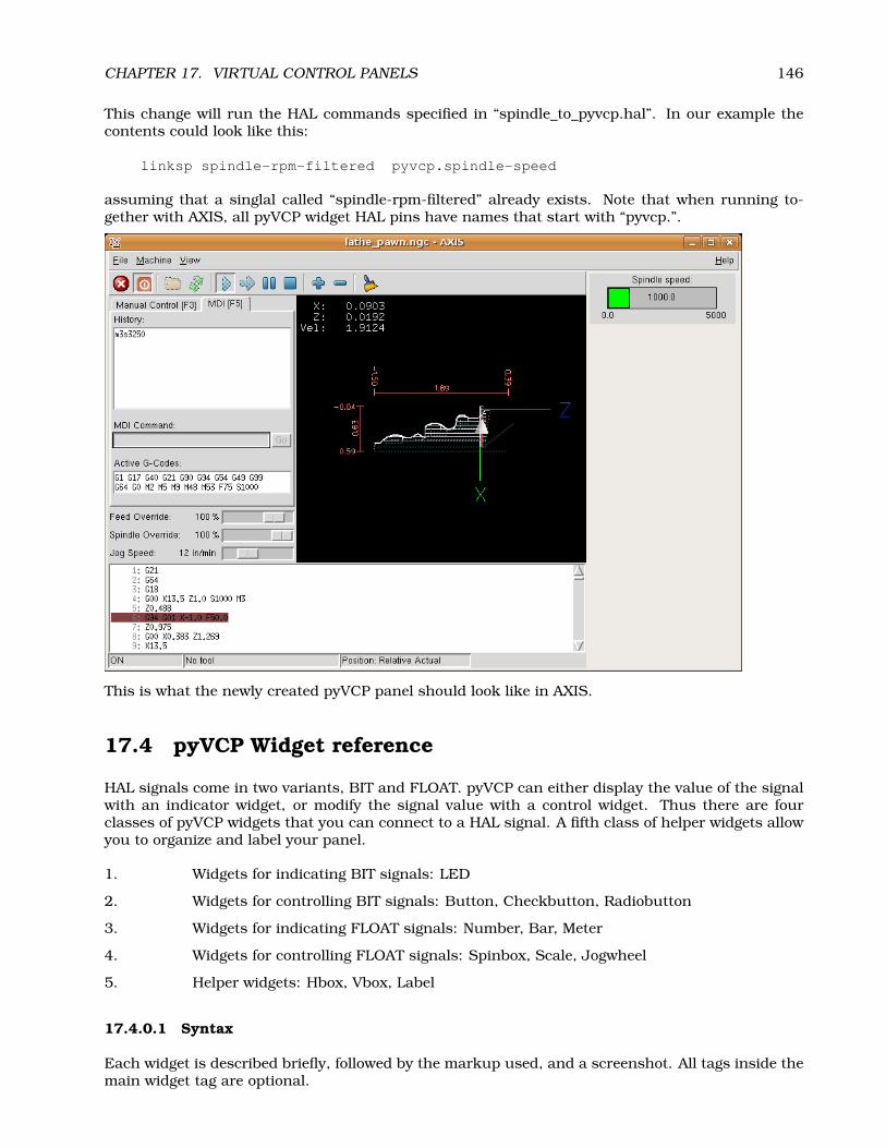
CHAPTER 17. VIRTUAL CONTROL PANELS 146
This change will run the HAL commands specified in “spindle_to_pyvcp.hal”. In our example thecontents could look like this:
linksp spindle-rpm-filtered pyvcp.spindle-speed
assuming that a singlal called “spindle-rpm-filtered” already exists. Note that when running to-gether with AXIS, all pyVCP widget HAL pins have names that start with “pyvcp.”.
This is what the newly created pyVCP panel should look like in AXIS.
17.4 pyVCP Widget reference
HAL signals come in two variants, BIT and FLOAT. pyVCP can either display the value of the signalwith an indicator widget, or modify the signal value with a control widget. Thus there are fourclasses of pyVCP widgets that you can connect to a HAL signal. A fifth class of helper widgets allowyou to organize and label your panel.
1. Widgets for indicating BIT signals: LED
2. Widgets for controlling BIT signals: Button, Checkbutton, Radiobutton
3. Widgets for indicating FLOAT signals: Number, Bar, Meter
4. Widgets for controlling FLOAT signals: Spinbox, Scale, Jogwheel
5. Helper widgets: Hbox, Vbox, Label
17.4.0.1 Syntax
Each widget is described briefly, followed by the markup used, and a screenshot. All tags inside themain widget tag are optional.

CHAPTER 17. VIRTUAL CONTROL PANELS 147
17.4.1 LED
A LED is used to indicate the status of a BIT signal. The LED color will be on_color when the BITsignal is true, and off_color otherwise.
<led><halpin>"my-led"</halpin><size>50</size><on_color>"blue"</on_color><off_color>"black"</off_color>
</led>
<halpin> sets the name of the pin, default is “led.n”, where n is an integer<size> sets the size of the led, default is 20<on_color> sets the color of the LED when the pin is true. default is “green”<off_color> sets the color of the LED when the pin is false. default is “ref”
17.4.2 Button
A button is used to control a BIT pin. The pin will be set True when the button is pressed and helddown, and will be set False when the button is released.
<button><halpin>"my-button"</halpin><text>"ON"</text>
</button>
17.4.3 Checkbutton
A checkbutton controls a BIT pin. The pin will be set True when the button is checked, and falsewhen the button is unchecked.
<checkbutton><halpin>"my-checkbutton"</halpin>
</checkbutton>
An unchecked checkbutton: , and a checked one:
17.4.4 Radiobutton
A radiobutton will set one of a number of BIT pins true. The other pins are set false.
<radiobutton><choices>["one","two","three"]</choices><halpin>"my-radio"</halpin>
</radiobutton>

CHAPTER 17. VIRTUAL CONTROL PANELS 148
Note that the HAL pins in the example above will me named my-radio.one, my-radio.two, and my-radio.three
17.4.5 Number
The number widget displays the value of a FLOAT signal.
<number><halpin>"my-number"</halpin><font>(’Helvetica’,50)</font><format>"+4.3f"</format>
</number>
<font> is a Tkinter font type and size specification. Note that on Ubuntu 6.06 ’Helvetica’ is notavailable in sizes above ca 40 or 50. One font that will show up to at least size 200 is ’courier 10pitch’, so for a really big Number widget you could specify:
<font>(’courier 10 pitch’,100)</font>
<format> is a ’C-style’ format specified that determines how the number is displayed.
17.4.6 Bar
A bar widget displays the value of a FLOAT signal both graphically using a bar display and numeri-cally.
<bar><halpin>"my-bar"</halpin><min_>0</min_><max_>123</max_><bgcolor>"grey"</bgcolor><fillcolor>"red"</fillcolor>
</bar>

CHAPTER 17. VIRTUAL CONTROL PANELS 149
17.4.7 Meter
Meter displays the value of a FLOAT signal using a traditional dial indicator.
<meter><halpin>"my-meter"</halpin><text>"Voltage"</text><size>300</size><min_>-12</min_><max_>33</max_>
</meter>
17.4.8 Spinbox
Spinbox controls a FLOAT pin. You increase or decrease the value of the pin by ’resolution’ by eitherpressing on the arrows, or pointing at the spinbox and rolling your mouse-wheel.
<spinbox><halpin>"my-spibox"</halpin><min_>-12</min_><max_>33</max_><resolution>0.1</resolution><format>"2.3f"</format><font>(’Arial’,30)</font>
</spinbox>
17.4.9 Scale
Scale controls a FLOAT pin. You increase or decrease the value of the pin be either dragging theslider, or pointing at the scale and rolling your mouse-wheel.
<scale><halpin>"my-scale"</halpin><resolution>0.1</resolution><orient>HORIZONTAL</orient><min_>-33</min_><max_>26</max_>

CHAPTER 17. VIRTUAL CONTROL PANELS 150
</scale>
17.4.10 Jogwheel
Jogwheel mimics a real jogwheel by outputting a FLOAT pin which counts up or down as the wheelis turned, either by dragging in a cricular motion, or by rolling the mouse-wheel.
<jogwheel><halpin>"my-wheel"</halpin><cpr>45</cpr><size>250</size>
</jogwheel>
17.4.11 Hbox
Use a Hbox when you want to stack widgets horizontally next to eachother.
<hbox><label><text>"a vbox:"</text></label><led></led><number></number><bar></bar>
</hbox>
17.4.12 Vbox
Use a Vbox when you want to stack widgets verticallyon top of eachother.
<vbox><label><text>"a vbox:"</text></label><led></led><number></number><bar></bar>

CHAPTER 17. VIRTUAL CONTROL PANELS 151
</vbox>
17.4.13 Label
A label is a piece of text on your panel.
<label><text>"This is a Label:"</text><font>(’Helvetica’,20)</font>
</label>
17.5 VCP: A small example
NOTE: VCP is deprecated, and will most likely not be getting any new development or additionalwidgets. We strongly recommend using pyVCP. Both pyVCP and VCP are included in EMC version2.1, but it is likely that only pyVCP will be included in EMC 2.2. 1
Place the following in the file tiny.vcp:
vcp main-window
box button
halpin = vcp.pushbuttonlabel text = "Push Me"
LED
halpin = vcp.light
The above file describes a tiny Virtual Control Panel, with one push button, and one light. To seewhat it looks like, we need to start HAL:
$halrunhalcmd:
1A .vcp to .xml translator that takes a vcp file and turns it into one that pyVCP can use is on my to-do list. That wouldenable VCP users to easily switch over to pyVCP. If such a translator is written, VCP may be removed from the version 2.2release.

CHAPTER 17. VIRTUAL CONTROL PANELS 152
Next we load halvcp, and give it the name of our .vcp file:
halcmd: loadusr halvcp tiny.vcphalcmd:
There may be some text printed as halvcp parses the tiny.vcp file, but when it finishes, there shouldbe a small window on your screen, with a button and an LED. It will look something like figure 17.1.
Figure 17.1: tiny.vcp on the screen
So, we have a button and an LED, but they aren’t connected to anything, so nothing happens whenyou push the button. However, the LED and the button both have HAL pins associated with them:
halcmd: show pinComponent Pins:Owner Type Dir Value Name03 bit IN FALSE vcp.light03 bit OUT FALSE vcp.pushbutton
halcmd:
To make something happen, we can connect a HAL signal between the button and the light:
halcmd: newsig jumper bithalcmd: linksp jumper vcp.pushbuttonhalcmd: linksp jumper vcp.lighthalcmd: show sigSignals:Type Value Namebit FALSE jumper
==> vcp.light<== vcp.pushbutton
halcmd:
Now push the button, and the the LED should light up!
17.6 VCP: Another small example with EMC
Place the following in the file estop.vcp:
vcp main-window
toggle halpin = vcp.estop
In your .hal file, remove any existing signal linked to iocontrol.0.emc-enable-in and add thefollowing lines:

CHAPTER 17. VIRTUAL CONTROL PANELS 153
loadusr -W halvcp estop.vcpnewsig estop bitlinkps vcp.estop => estoplinkps estop => iocontrol.0.emc-enable-in
Now, when running your machine, the ESTOP button in the GUI is disabled, and the ESTOP buttonin the VCP window is used instead.
17.7 VCP Syntax
17.7.1 Block
A block’s format is:
tag contents
The contents can consist of attributes that describe the block, or other blocks that nest inside it.
A attribute’s format is
name = value
The attribute names that are acceptable for each block depend on the block tag, and will be listedlater.

Part VI
Advanced topics
154

Chapter 18
Kinematics in EMC2
18.1 Introduction
When we talk about CNC machines, we usually think about machines that are commanded to moveto certain locations and perform various tasks. In order to have an unified view of the machinespace, and to make it fit the human point of view over 3D space, most of the machines (if not all)use a common coordinate system called the Cartesian Coordinate System.
The Cartesian Coordinate system is composed of 3 axes (X, Y, Z) each perpendicular to the other 2.1
When we talk about a G-code program (RS274NGC) we talk about a number of commands (G0,G1, etc.) which have positions as parameters (X- Y- Z-). These positions refer exactly to Cartesianpositions. Part of the EMC2 motion controller is responsible for translating those positions intopositions which correspond to the machine kinematics2.
18.1.1 Joints vs. Axes
A joint of a CNC machine is a one of the physical degrees of freedom of the machine. This might belinear (leadscrews) or rotary (rotary tables, robot arm joints). There can be any number of joints ona certain machine. For example a typical robot has 6 joints, and a typical simple milling machinehas only 3.
There are certain machines where the joints are layed out to match kinematics axes (joint 0 alongaxis X, joint 1 along axis Y, joint 2 along axis Z), and these machines are called Cartesian machines(or machines with Trivial Kinematics). These are the most common machines used in milling, butare not very common in other domains of machine control (e.g. welding: puma-typed robots).
18.2 Trivial Kinematics
As we said there is a group of machines in which each joint is placed along one of the Cartesianaxes. On these machines the mapping from Cartesian space (the G-code program) to the joint space(the actual actuators of the machine) is trivial. It is a simple 1:1 mapping:
pos->tran.x = joints[0];pos->tran.y = joints[1];
1The word “axes” is also commonly (and wrongly) used when talking about CNC machines, and referring to the movingdirections of the machine.
2Kinematics: a two way function to transform from Cartesian space to joint space
155

CHAPTER 18. KINEMATICS IN EMC2 156
pos->tran.z = joints[2];pos->a = joints[3];pos->b = joints[4];pos->c = joints[5];
In the above code snippet one can see how the mapping is done: the X position is identical withthe joint 0, Y with joint 1 etc. The above refers to the direct kinematics (one way of the trans-formation) whereas the next code part refers to the inverse kinematics (or the inverse way of thetransformation):
joints[0] = pos->tran.x;joints[1] = pos->tran.y;joints[2] = pos->tran.z;joints[3] = pos->a;joints[4] = pos->b;joints[5] = pos->c;
As one can see, it’s pretty straightforward to do the transformation for a trivial kins (or Cartesian)machine. It gets a bit more complicated if the machine is missing one of the axes.34
18.3 Non-trivial kinematics
There can be quite a few types of machine setups (robots: puma, scara; hexapods etc.). Each ofthem is set up using linear and rotary joints. These joints don’t usually match with the Cartesiancoordinates, therefor there needs to be a kinematics function which does the conversion (actually 2functions: forward and inverse kinematics function).
To illustrate the above, we will analyze a simple kinematics called bipod (a simplified version of thetripod, which is a simplified version of the hexapod).
The Bipod we are talking about is a device that consists of 2 motors placed on a wall, from which adevice is hanged using some wire. The joints in this case are the distances from the motors to thedevice (named AD and BD in figure 18.1).
The position of the motors is fixed by convention. Motor A is in (0,0), which means that its Xcoordinate is 0, and its Y coordinate is also 0. Motor B is placed in (Bx, 0), which means that its Xcoordinate is Bx.
Our tooltip will be in point D which gets defined by the distances AD and BD, and by the Cartesiancoordinates Dx, Dy.
The job of the kinematics is to transform from joint lengths (AD, BD) to Cartesian coordinates (Dx,Dy) and vice-versa.
18.3.1 Forward transformation
To transform from joint space into Cartesian space we will use some trigonometry rules (the righttriangles determined by the points (0,0), (Dx,0), (Dx,Dy) and the triangle (Dx,0), (Bx,0) and (Dx,Dy).
we can easily see that AD2 = x2 + y2, likewise BD2 = (Bx− x)2 + y2.
If we subtract one from the other we will get:
3If a machine (e.g. a lathe) is set up with only the axes X,Z & A, and the EMC2 inifile holds only these 3 joints defined,then the above matching will be faulty. That is because we actually have (joint0=x, joint1=Z, joint2=A) whereas the aboveassumes joint1=Y. To make it easily work in EMC2 one needs to define all axes (XYZA), then use a simple loopback in HALfor the unused Y axis.
4One other way of making it work, is by changing the matching code and recompiling the software.

CHAPTER 18. KINEMATICS IN EMC2 157
Figure 18.1: Bipod setup
AD2 −BD2 = x2 + y2 − x2 + 2 ∗ x ∗Bx−Bx2 − y2
and therefore:
x =AD2 −BD2 + Bx2
2 ∗Bx
From there we calculate:
y =√
AD2 − x2
Note that the calculation for y involves the square root of a difference, which may not result in areal number. If there is no single Cartesian coordinate for this joint position, then the position issaid to be a singularity. In this case, the forward kinematics return -1.
Translated to actual code:
double AD2 = joints[0] * joints[0];double BD2 = joints[1] * joints[1];double x = (AD2 - BD2 + Bx * Bx) / (2 * Bx);double y2 = AD2 - x * x;if(y2 < 0) return -1;pos->tran.x = x;pos->tran.y = sqrt(y2);return 0;

CHAPTER 18. KINEMATICS IN EMC2 158
18.3.2 Inverse transformation
The inverse kinematics is lots easier in our example, as we can write it directly:
AD =√
x2 + y2
BD =√
(Bx− x)2 + y2
or translated to actual code:
double x2 = pos->tran.x * pos->tran.x;double y2 = pos->tran.y * pos->tran.y;joints[0] = sqrt(x2 + y2);joints[1] = sqrt((Bx - pos->tran.x)*(Bx - pos->tran.x) + y2);return 0;
18.4 Implementation details
A kinematics module is implemented as a HAL component, and is permitted to export pins andparameters. It consists of several functions:
• int kinematicsForward(const double *joint, EmcPose *world, const KINEMATICS_FORWARD_FLAGS
*fflags, KINEMATICS_INVERSE_FLAGS *iflags)
Implements the forward kinematics function as described in section 18.3.1.
• extern int kinematicsInverse(const EmcPose * world, double *joints, const KINEMATICS_INVERSE_FLAGS
*iflags, KINEMATICS_FORWARD_FLAGS *fflags)
Implements the inverse kinematics function as described in section 18.3.2.
• extern KINEMATICS_TYPE kinematicsType(void)
Returns the kinematics type identifier.
• int kinematicsHome(EmcPose *world, double *joint, KINEMATICS_FORWARD_FLAGS *fflags,KINEMATICS_INVERSE_FLAGS *iflags)
The home kinematics function sets all its arguments to their proper values at the known homeposition. When called, these should be set, when known, to initial values, e.g., from an INIfile. If the home kinematics can accept arbitrary starting points, these initial values should beused.
• int rtapi_app_main(void)
• void rtapi_app_exit(void)
These are the standard setup and tear-down functions of RTAPI modules.

Part VII
Tuning
159

160
18.5 Tuning servo systems

161
18.5.1 PID Controller
A proportional-integral-derivative controller (PID controller) is a common feedback loop componentin industrial control systems.5
The Controller compares a measured value from a process (typically an industrial process) with areference setpoint value. The difference (or "error" signal) is then used to calculate a new value fora manipulatable input to the process that brings the process’ measured value back to its desiredsetpoint.
Unlike simpler control algorithms, the PID controller can adjust process outputs based on thehistory and rate of change of the error signal, which gives more accurate and stable control. (Itcan be shown mathematically that a PID loop will produce accurate, stable control in cases wherea simple proportional control would either have a steady-state error or would cause the process tooscillate).
18.5.1.1 Control loop basics
Intuitively, the PID loop tries to automate what an intelligent operator with a gauge and a controlknob would do. The operator would read a gauge showing the output measurement of a process, anduse the knob to adjust the input of the process (the "action") until the process’s output measurementstabilizes at the desired value on the gauge.
In older control literature this adjustment process is called a "reset" action. The position of theneedle on the gauge is a "measurement", "process value" or "process variable". The desired value onthe gauge is called a "setpoint" (also called "set value"). The difference between the gauge’s needleand the setpoint is the "error".
A control loop consists of three parts:
1. Measurement by a sensor connected to the process (e.g. encoder),
2. Decision in a controller element,
3. Action through an output device such as an motor.
As the controller reads a sensor, it subtracts this measurement from the "setpoint" to determine the"error". It then uses the error to calculate a correction to the process’s input variable (the "action")so that this correction will remove the error from the process’s output measurement.
In a PID loop, correction is calculated from the error in three ways: cancel out the current er-ror directly (Proportional), the amount of time the error has continued uncorrected (Integral), andanticipate the future error from the rate of change of the error over time (Derivative).
A PID controller can be used to control any measurable variable which can be affected by manipu-lating some other process variable. For example, it can be used to control temperature, pressure,flow rate, chemical composition, speed, or other variables. Automobile cruise control is an exampleof a process outside of industry which utilizes crude PID control.
Some control systems arrange PID controllers in cascades or networks. That is, a "master" controlproduces signals used by "slave" controllers. One common situation is motor controls: one oftenwants the motor to have a controlled speed, with the "slave" controller (often built into a variablefrequency drive) directly managing the speed based on a proportional input. This "slave" input isfed by the "master" controllers’ output, which is controlling based upon a related variable.
18.5.1.2 Theory
"PID" is named after its three correcting calculations, which all add to and adjust the controlledquantity. These additions are actually "subtractions" of error, because the proportions are usuallynegative:
5This Subsection is taken from an much more extensive article found at http://en.wikipedia.org/wiki/PID_controller

162
18.5.1.2.0.1 Proportional To handle the present, the error is multiplied by a (negative) constantP (for "proportional"), and added to (subtracting error from) the controlled quantity. P is only validin the band over which a controller’s output is proportional to the error of the system. Note thatwhen the error is zero, a proportional controller’s output is zero.
18.5.1.2.0.2 Integral To learn from the past, the error is integrated (added up) over a period oftime, and then multiplied by a (negative) constant I (making an average), and added to (subtractingerror from) the controlled quantity. I averages the measured error to find the process output’s aver-age error from the setpoint. A simple proportional system either oscillates, moving back and fortharound the setpoint because there’s nothing to remove the error when it overshoots, or oscillatesand/or stabilizes at a too low or too high value. By adding a negative proportion of (i.e. subtractingpart of) the average error from the process input, the average difference between the process outputand the setpoint is always being reduced. Therefore, eventually, a well-tuned PID loop’s processoutput will settle down at the setpoint.
18.5.1.2.0.3 Derivative To handle the future, the first derivative (the slope of the error) overtime is calculated, and multiplied by another (negative) constant D, and also added to (subtractingerror from) the controlled quantity. The derivative term controls the response to a change in thesystem. The larger the derivative term, the more rapidly the controller responds to changes in theprocess’s output.
More technically, a PID loop can be characterized as a filter applied to a complex frequency-domainsystem. This is useful in order to calculate whether it will actually reach a stable value. If the valuesare chosen incorrectly, the controlled process input can oscillate, and the process output may neverstay at the setpoint.
18.5.1.3 Loop Tuning
"Tuning" a control loop is the adjustment of its control parameters (gain/proportional band, integralgain/reset, derivative gain/rate) to the optimum values for the desired control response. The opti-mum behavior on a process change or setpoint change varies depending on the application. Someprocesses must not allow an overshoot of the process variable from the setpoint. Other processesmust minimize the energy expended in reaching a new setpoint. Generally stability of response isrequired and the process must not oscillate for any combination of process conditions and setpoints.
Tuning of loops is made more complicated by the response time of the process; it may take minutesor hours for a setpoint change to produce a stable effect. Some processes have a degree of non-linearity and so parameters that work well at full-load conditions don’t work when the process isstarting up from no-load. This section describes some traditional manual methods for loop tuning.
There are several methods for tuning a PID loop. The choice of method will depend largely onwhether or not the loop can be taken "offline" for tuning, and the response speed of the system.If the system can be taken offline, the best tuning method often involves subjecting the system toa step change in input, measuring the output as a function of time, and using this response todetermine the control parameters.
18.5.1.3.0.4 Simple method If the system must remain online, one tuning method is to first setthe I and D values to zero. Increase the P until the output of the loop oscillates. Then increase Iuntil oscillation stops. Finally, increase D until the loop is acceptably quick to reach its reference. Afast PID loop tuning usually overshoots slightly to reach the setpoint more quickly; however, somesystems cannot accept overshoot.
Parameter Rise Time Overshoot Settling Time S.S. ErrorP Decrease Increase Small Change DecreaseI Decrease Increase Increase EliminateD Small Change Decrease Decrease Small Change

163
Effects of increasing parameters
18.5.1.3.0.5 Ziegler-Nichols method Another tuning method is formally known as the "Ziegler-Nichols method", introduced by John G. Ziegler and Nathaniel B. Nichols. It starts in the same wayas the method described before: first set the I and D gains to zero and then increase the P gain untilthe output of the loop starts to oscillate. Write down the critical gain (Kc) and the oscillation periodof the output (Pc). Then adjust the P, I and D controls as the table shows:
Control type P I DP 0.5 KcPI 0.45 Kc Pc/1.2
PID 0.6 Kc Pc/2 Pc/8

164
18.6 Tuning stepper systems

Appendix A
Glossary of Common Terms Used inthe EMC Documents
A listing of terms and what they mean. Some terms have a general meaning and several additionalmeanings for users, installers, and developers.
Acme Screw A type of lead-screw A that uses an acme thread form. Acme threads have somewhatlower friction and wear than simple triangular threads, but ball-screws A are lower yet. Mostmanual machine tools use acme lead-screws.
Axis One of the computer control movable parts of the machine. For a typical vertical mill, the tableis the X axis, the saddle is the Y axis, and the quill or knee is the Z axis. Additional linear axesparallel to X, Y, and Z are called U, V, and W respectively. Angular axes like rotary tables arereferred to as A, B, and C.
Backlash The amount of "play" or lost motion that occurs when direction is reversed in a leadscrew A. or other mechanical motion driving system. It can result from nuts that are looseon leadscrews, slippage in belts, cable slack, "wind-up" in rotary couplings, and other placeswhere the mechanical system is not "tight". Backlash will result in inaccurate motion, or inthe case of motion caused by external forces (think cutting tool pulling on the work piece) theresult can be broken cutting tools. This can happen because of the sudden increase in chipload on the cutter as the work piece is pulled across the backlash distance by the cutting tool.
Backlash Compensation - Any technique that attempts to reduce the effect of backlash withoutactually removing it from the mechanical system. This is typically done in software in thecontroller. This can correct the final resting place of the part in motion but fails to solveproblems related to direction changes while in motion (think circular interpolation) and motionthat is caused when external forces (think cutting tool pulling on the work piece) are the sourceof the motion.
Ball Screw A type of lead-screw that uses small hardened steel balls between the nut A and screwto reduce friction. Ball-screws have very low friction and backlash A, but are usually quiteexpensive.
Ball Nut A special nut designed for use with a ball-screw. It contains an internal passage to re-circulate the balls from one end of the screw to the other.
CNC Computer Numerical Control. The general term used to refer to computer control of machin-ery. Instead of a human operator turning cranks to move a cutting tool, CNC uses a computerand motors to move the tool, based on a part program A.
Coordinate Measuring Machine A Coordinate Measuring Machine is used to make many accuratemeasurements on parts. These machines can be used to create CAD data for parts where no
165

APPENDIX A. GLOSSARY OF COMMON TERMS USED IN THE EMC DOCUMENTS 166
drawings can be found, when a hand-made prototype needs to be digitized for moldmaking, orto check the accuracy of machined or molded parts.
DRO A Digital Read Out is a device attached to the slides of a machine tool or other device whichhas parts that move in a precise manner to indicate the current location of the tool with respectto some reference position. Nearly all DRO’s use linear quadrature encoders to pick up positioninformation from the machine.
EDM EDM is a method of removing metal in hard or difficult to machine or tough metals, or whererotating tools would not be able to produce the desired shape in a cost-effective manner. Anexcellent example is rectangular punch dies, where sharp internal corners are desired. Millingoperations can not give sharp internal corners with finite diameter tools. A wire EDM machinecan make internal corners with a radius only slightly larger than the wire’s radius. A ’sinker’EDM cam make corners with a radius only slightly larger than the radius on the corner of theconvex EDM electrode.
EMC The Enhanced Machine Controller. Initially a NIST A project. EMC is able to run a wide rangeof motion devices.
EMCIO The module within EMCA that handles general purpose I/O, unrelated to the actual motionof the axes.
EMCMOT The module within EMC A that handles the actual motion of the cutting tool. It runs asa real-time program and directly controls the motors.
Encoder A device to measure position. Usually a machanical-optical device, which outputs aquadrature signal. The signal can be counted by special hardware, or directly by the par-port with emc2.
Feed Relatively slow, controlled motion of the tool used when making a cut.
Feedrate The speed at which a motion occurs. In manual mode, jog speed can be set from thegraphical interface. In auto or mdi mode feedrate is commanded using a (f) word. F10 wouldmean ten units per minute.
Feedback
Feedrate Override A manual, operator controlled change in the rate at which the tool moves whilecutting. Often used to allow the operator to adjust for tools that are a little dull, or anythingelse that requires the feed rate to be “tweaked”.
G-Code The generic term used to refer to the most common part programming language. There areseveral dialects of G-code, EMC uses RS274/NGC A.
GUI Graphical User Interface.
General A type of interface that allows communications between a computer and human (inmost cases) via the manipulation of icons and other elements (widgets) on a computerscreen.
EMC An application that presents a graphical screen to the machine operator allowing manip-ulation of machine and the corresponding controlling program.
Home A specific location in the machine’s work envelope that is used to make sure the computerand the actual machine both agree on the tool position.
ini file A text file that contains most of the information that configures EMC A for a particularmachine
Joint_Coordinates: These specify the angles between the individual joints of the machine. Kine-matics

APPENDIX A. GLOSSARY OF COMMON TERMS USED IN THE EMC DOCUMENTS 167
Jog Manually moving an axis of a machine. Jogging either moves the axis a fixed amount for eachkey-press, or moves the axis at a constant speed as long as you hold down the key.
kernel-space
Kinematics The position relationship between world coordinates A and joint coordinates A of amachine. There are two types of kinematics. Forward kinematics is used to calculate world co-ordinates from joint coordinates. Inverse kinematics is used for exactly opposite purpose.Notethat kinematics does not take into account, the forces, moments etc. on the machine. It is forpositioning only.
Lead-screw An screw that is rotated by a motor to move a table or other part of a machine. Lead-screws are usually either ball-screws A or acme screws A, although conventional triangularthreaded screws may be used where accuracy and long life are not as important as low cost.
MDI Manual Data Input. This is a mode of operation where the controller executes single lines ofG-code A as they are typed by the operator.
NIST National Institute of Standards and Technology. An agency of the Department of Commercein the United States.
Offsets
Part Program A description of a part, in a language that the controller can understand. For EMC,that language is RS-274/NGC, commonly known as G-code A.
Rapid Fast, possibly less precise motion of the tool, commonly used to move between cuts. If thetool meets the material during a rapid, it is probably a bad thing!
Real-time Software that is intended to meet very strict timing deadlines. Under Linux, in order tomeet these requirements it is necessary to install RTAI A or RTLINUX A and build the softwareto run in those special environments. For this reason real-time software runs in kernel-space.
RTAI Real Time Application Interface, see http://www.aero.polimi.it/ rtai/ http://www.aero.polimi.it/~rtai/, one of two real-time extensions for Linux that EMC can use to achievereal-time A performance.
RTLINUX See http://www.rtlinux.org http://www.rtlinux.org, one of two real-time extensionsfor Linux that EMC can use to achieve real-time A performance.
RS-274/NGC The formal name for the language used by EMC A part programs A.
Servo Motor
Servo Loop
Spindle On a mill or drill, the spindle holds the cutting tool. On a lathe, the spindle holds theworkpiece.
Stepper Motor A type of motor that turns in fixed steps. By counting steps, it is possible to deter-mine how far the motor has turned. If the load exceeds the torque capability of the motor, itwill skip one or more steps, causing position errors.
TASK The module within EMC A that coordinates the overall execution and interprets the partprogram.
Tcl/Tk A scripting language and graphical widget toolkit with which EMC’s most popular GUI’s Awere written.
World Coordinates This is the absolute frame of reference. It gives coordinates in terms of a fixedreference frame that is attached to some point (generally the base) of the machine tool.

Appendix B
Legal Section
Handbook Copyright Terms
Copyright (c) 2000 LinuxCNC.orgPermission is granted to copy, distribute and/or modify this document under the
terms of the GNU Free Documentation License, Version 1.1 or any later version publishedby the Free Software Foundation; with no Invariant Sections, no Front-Cover Texts, andone Back-Cover Text: "This EMC Handbook is the product of several authors writing forlinuxCNC.org. As you find it to be of value in your work, we invite you to contribute to itsrevision and growth." A copy of the license is included in the section entitled "GNU FreeDocumentation License". If you do not find the license you may order a copy from FreeSoftware Foundation, Inc. 59 Temple Place, Suite 330, Boston, MA 02111-1307
B.1 GNU Free Documentation License Version 1.1, March 2000
Copyright (C) 2000 Free Software Foundation, Inc. 59 Temple Place, Suite 330, Boston, MA 02111-1307 USA Everyone is permitted to copy and distribute verbatim copies of this license document,but changing it is not allowed.
B.1.1 GNU Free Documentation License Version 1.1, March 2000
Copyright (C) 2000 Free Software Foundation, Inc. 59 Temple Place, Suite 330, Boston, MA 02111-1307 USAEveryone is permitted to copy and distribute verbatim copies of this license document, but changing it is notallowed.
0. PREAMBLE
The purpose of this License is to make a manual, textbook, or other written document "free" in the sense offreedom: to assure everyone the effective freedom to copy and redistribute it, with or without modifying it,either commercially or noncommercially. Secondarily, this License preserves for the author and publisher away to get credit for their work, while not being considered responsible for modifications made by others.
This License is a kind of "copyleft", which means that derivative works of the document must themselves befree in the same sense. It complements the GNU General Public License, which is a copyleft license designedfor free software.
We have designed this License in order to use it for manuals for free software, because free software needsfree documentation: a free program should come with manuals providing the same freedoms that the softwaredoes. But this License is not limited to software manuals; it can be used for any textual work, regardless ofsubject matter or whether it is published as a printed book. We recommend this License principally for workswhose purpose is instruction or reference.
168
APPENDIX B. LEGAL SECTION 169
1. APPLICABILITY AND DEFINITIONS
This License applies to any manual or other work that contains a notice placed by the copyright holder sayingit can be distributed under the terms of this License. The "Document", below, refers to any such manual orwork. Any member of the public is a licensee, and is addressed as "you".
A "Modified Version" of the Document means any work containing the Document or a portion of it, either copiedverbatim, or with modifications and/or translated into another language.
A "Secondary Section" is a named appendix or a front-matter section of the Document that deals exclusivelywith the relationship of the publishers or authors of the Document to the Document’s overall subject (or torelated matters) and contains nothing that could fall directly within that overall subject. (For example, if theDocument is in part a textbook of mathematics, a Secondary Section may not explain any mathematics.) Therelationship could be a matter of historical connection with the subject or with related matters, or of legal,commercial, philosophical, ethical or political position regarding them.
The "Invariant Sections" are certain Secondary Sections whose titles are designated, as being those of InvariantSections, in the notice that says that the Document is released under this License.
The "Cover Texts" are certain short passages of text that are listed, as Front-Cover Texts or Back-Cover Texts,in the notice that says that the Document is released under this License.
A "Transparent" copy of the Document means a machine-readable copy, represented in a format whose specifi-cation is available to the general public, whose contents can be viewed and edited directly and straightforwardlywith generic text editors or (for images composed of pixels) generic paint programs or (for drawings) some widelyavailable drawing editor, and that is suitable for input to text formatters or for automatic translation to a vari-ety of formats suitable for input to text formatters. A copy made in an otherwise Transparent file format whosemarkup has been designed to thwart or discourage subsequent modification by readers is not Transparent. Acopy that is not "Transparent" is called "Opaque".
Examples of suitable formats for Transparent copies include plain ASCII without markup, Texinfo input format,LATEX input format, SGML or XML using a publicly available DTD, and standard-conforming simple HTMLdesigned for human modification. Opaque formats include PostScript, PDF, proprietary formats that can beread and edited only by proprietary word processors, SGML or XML for which the DTD and/or processing toolsare not generally available, and the machine-generated HTML produced by some word processors for outputpurposes only.
The "Title Page" means, for a printed book, the title page itself, plus such following pages as are needed to hold,legibly, the material this License requires to appear in the title page. For works in formats which do not haveany title page as such, "Title Page" means the text near the most prominent appearance of the work’s title,preceding the beginning of the body of the text.
2. VERBATIM COPYING
You may copy and distribute the Document in any medium, either commercially or noncommercially, providedthat this License, the copyright notices, and the license notice saying this License applies to the Documentare reproduced in all copies, and that you add no other conditions whatsoever to those of this License. Youmay not use technical measures to obstruct or control the reading or further copying of the copies you makeor distribute. However, you may accept compensation in exchange for copies. If you distribute a large enoughnumber of copies you must also follow the conditions in section 3.
You may also lend copies, under the same conditions stated above, and you may publicly display copies.
3. COPYING IN QUANTITY
If you publish printed copies of the Document numbering more than 100, and the Document’s license noticerequires Cover Texts, you must enclose the copies in covers that carry, clearly and legibly, all these CoverTexts: Front-Cover Texts on the front cover, and Back-Cover Texts on the back cover. Both covers must alsoclearly and legibly identify you as the publisher of these copies. The front cover must present the full title withall words of the title equally prominent and visible. You may add other material on the covers in addition.Copying with changes limited to the covers, as long as they preserve the title of the Document and satisfy theseconditions, can be treated as verbatim copying in other respects.
If the required texts for either cover are too voluminous to fit legibly, you should put the first ones listed (asmany as fit reasonably) on the actual cover, and continue the rest onto adjacent pages.
If you publish or distribute Opaque copies of the Document numbering more than 100, you must either includea machine-readable Transparent copy along with each Opaque copy, or state in or with each Opaque copy apublicly-accessible computer-network location containing a complete Transparent copy of the Document, free

APPENDIX B. LEGAL SECTION 170
of added material, which the general network-using public has access to download anonymously at no chargeusing public-standard network protocols. If you use the latter option, you must take reasonably prudent steps,when you begin distribution of Opaque copies in quantity, to ensure that this Transparent copy will remainthus accessible at the stated location until at least one year after the last time you distribute an Opaque copy(directly or through your agents or retailers) of that edition to the public.
It is requested, but not required, that you contact the authors of the Document well before redistributing anylarge number of copies, to give them a chance to provide you with an updated version of the Document.
4. MODIFICATIONS
You may copy and distribute a Modified Version of the Document under the conditions of sections 2 and 3above, provided that you release the Modified Version under precisely this License, with the Modified Versionfilling the role of the Document, thus licensing distribution and modification of the Modified Version to whoeverpossesses a copy of it. In addition, you must do these things in the Modified Version:
A. Use in the Title Page (and on the covers, if any) a title distinct from that of the Document, and from thoseof previous versions (which should, if there were any, be listed in the History section of the Document). Youmay use the same title as a previous version if the original publisher of that version gives permission. B. Liston the Title Page, as authors, one or more persons or entities responsible for authorship of the modificationsin the Modified Version, together with at least five of the principal authors of the Document (all of its principalauthors, if it has less than five). C. State on the Title page the name of the publisher of the Modified Version, asthe publisher. D. Preserve all the copyright notices of the Document. E. Add an appropriate copyright notice foryour modifications adjacent to the other copyright notices. F. Include, immediately after the copyright notices,a license notice giving the public permission to use the Modified Version under the terms of this License, inthe form shown in the Addendum below. G. Preserve in that license notice the full lists of Invariant Sectionsand required Cover Texts given in the Document’s license notice. H. Include an unaltered copy of this License.I. Preserve the section entitled "History", and its title, and add to it an item stating at least the title, year, newauthors, and publisher of the Modified Version as given on the Title Page. If there is no section entitled "History"in the Document, create one stating the title, year, authors, and publisher of the Document as given on itsTitle Page, then add an item describing the Modified Version as stated in the previous sentence. J. Preservethe network location, if any, given in the Document for public access to a Transparent copy of the Document,and likewise the network locations given in the Document for previous versions it was based on. These maybe placed in the "History" section. You may omit a network location for a work that was published at leastfour years before the Document itself, or if the original publisher of the version it refers to gives permission.K. In any section entitled "Acknowledgements" or "Dedications", preserve the section’s title, and preserve inthe section all the substance and tone of each of the contributor acknowledgements and/or dedications giventherein. L. Preserve all the Invariant Sections of the Document, unaltered in their text and in their titles.Section numbers or the equivalent are not considered part of the section titles. M. Delete any section entitled"Endorsements". Such a section may not be included in the Modified Version. N. Do not retitle any existingsection as "Endorsements" or to conflict in title with any Invariant Section.
If the Modified Version includes new front-matter sections or appendices that qualify as Secondary Sectionsand contain no material copied from the Document, you may at your option designate some or all of thesesections as invariant. To do this, add their titles to the list of Invariant Sections in the Modified Version’slicense notice. These titles must be distinct from any other section titles.
You may add a section entitled "Endorsements", provided it contains nothing but endorsements of your Mod-ified Version by various parties–for example, statements of peer review or that the text has been approved byan organization as the authoritative definition of a standard.
You may add a passage of up to five words as a Front-Cover Text, and a passage of up to 25 words as aBack-Cover Text, to the end of the list of Cover Texts in the Modified Version. Only one passage of Front-CoverText and one of Back-Cover Text may be added by (or through arrangements made by) any one entity. If theDocument already includes a cover text for the same cover, previously added by you or by arrangement madeby the same entity you are acting on behalf of, you may not add another; but you may replace the old one, onexplicit permission from the previous publisher that added the old one.
The author(s) and publisher(s) of the Document do not by this License give permission to use their names forpublicity for or to assert or imply endorsement of any Modified Version.
5. COMBINING DOCUMENTS
You may combine the Document with other documents released under this License, under the terms defined insection 4 above for modified versions, provided that you include in the combination all of the Invariant Sectionsof all of the original documents, unmodified, and list them all as Invariant Sections of your combined work inits license notice.
APPENDIX B. LEGAL SECTION 171
The combined work need only contain one copy of this License, and multiple identical Invariant Sections maybe replaced with a single copy. If there are multiple Invariant Sections with the same name but differentcontents, make the title of each such section unique by adding at the end of it, in parentheses, the name ofthe original author or publisher of that section if known, or else a unique number. Make the same adjustmentto the section titles in the list of Invariant Sections in the license notice of the combined work.
In the combination, you must combine any sections entitled "History" in the various original documents,forming one section entitled "History"; likewise combine any sections entitled "Acknowledgements", and anysections entitled "Dedications". You must delete all sections entitled "Endorsements."
6. COLLECTIONS OF DOCUMENTS
You may make a collection consisting of the Document and other documents released under this License, andreplace the individual copies of this License in the various documents with a single copy that is included in thecollection, provided that you follow the rules of this License for verbatim copying of each of the documents inall other respects.
You may extract a single document from such a collection, and distribute it individually under this License,provided you insert a copy of this License into the extracted document, and follow this License in all otherrespects regarding verbatim copying of that document.
7. AGGREGATION WITH INDEPENDENT WORKS
A compilation of the Document or its derivatives with other separate and independent documents or works,in or on a volume of a storage or distribution medium, does not as a whole count as a Modified Versionof the Document, provided no compilation copyright is claimed for the compilation. Such a compilation iscalled an "aggregate", and this License does not apply to the other self-contained works thus compiled withthe Document, on account of their being thus compiled, if they are not themselves derivative works of theDocument.
If the Cover Text requirement of section 3 is applicable to these copies of the Document, then if the Documentis less than one quarter of the entire aggregate, the Document’s Cover Texts may be placed on covers thatsurround only the Document within the aggregate. Otherwise they must appear on covers around the wholeaggregate.
8. TRANSLATION
Translation is considered a kind of modification, so you may distribute translations of the Document underthe terms of section 4. Replacing Invariant Sections with translations requires special permission from theircopyright holders, but you may include translations of some or all Invariant Sections in addition to the originalversions of these Invariant Sections. You may include a translation of this License provided that you alsoinclude the original English version of this License. In case of a disagreement between the translation and theoriginal English version of this License, the original English version will prevail.
9. TERMINATION
You may not copy, modify, sublicense, or distribute the Document except as expressly provided for underthis License. Any other attempt to copy, modify, sublicense or distribute the Document is void, and willautomatically terminate your rights under this License. However, parties who have received copies, or rights,from you under this License will not have their licenses terminated so long as such parties remain in fullcompliance.
10. FUTURE REVISIONS OF THIS LICENSE
The Free Software Foundation may publish new, revised versions of the GNU Free Documentation Licensefrom time to time. Such new versions will be similar in spirit to the present version, but may differ in detail toaddress new problems or concerns. See http:///www.gnu.org/copyleft/.
Each version of the License is given a distinguishing version number. If the Document specifies that a particularnumbered version of this License "or any later version" applies to it, you have the option of following the termsand conditions either of that specified version or of any later version that has been published (not as a draft)by the Free Software Foundation. If the Document does not specify a version number of this License, you maychoose any version ever published (not as a draft) by the Free Software Foundation.
ADDENDUM: How to use this License for your documents
To use this License in a document you have written, include a copy of the License in the document and putthe following copyright and license notices just after the title page:

APPENDIX B. LEGAL SECTION 172
Copyright (c) YEAR YOUR NAME. Permission is granted to copy, distribute and/or modify this documentunder the terms of the GNU Free Documentation License, Version 1.1 or any later version published by theFree Software Foundation; with the Invariant Sections being LIST THEIR TITLES, with the Front-Cover Textsbeing LIST, and with the Back-Cover Texts being LIST. A copy of the license is included in the section entitled"GNU Free Documentation License".
If you have no Invariant Sections, write "with no Invariant Sections" instead of saying which ones are invariant.If you have no Front-Cover Texts, write "no Front-Cover Texts" instead of "Front-Cover Texts being LIST";likewise for Back-Cover Texts.
If your document contains nontrivial examples of program code, we recommend releasing these examples inparallel under your choice of free software license, such as the GNU General Public License, to permit theiruse in free software.

Index
.emcrc, 22
ABORT, 10Acme Screw, 165ANGULAR UNITS, 26Auto, 8, 9AXIS, 5, 23AXIS 0,1,2,.., 23
Backlash, 165Backlash Compensation, 165Ball Nut, 165Ball Screw, 165BASE PERIOD, 24blocks, 43Bridgeport, 4
Carthesian machines, 155classicladder, 43CNC, 4, 40, 165CNC machines, 155Comments, 23CVS, 4
DISPLAY, 23DRO, 166
EDM, 166EMC, 23, 166emcgui, 5EMCIO, 7, 23, 166EMCMOT, 23, 166emcpanel, 5EMCTASK, 7enable signal, 99Encoder, 166encoder, 27, 43ESTOP, 10, 99
Feed, 166Feed Override, 166Feedrate, 166Feedrate Override, 10FERROR, 27freqgen, 43
G-Code, 166G-code, 8GNU-Linux, 3
GPL, 4
HAL, 5, 12, 22, 23, 40, 96HAL Component, 42HAL Function, 42HAL Parameter, 42HAL Physical-Pin, 42HAL Pin, 42HAL Signal, 42HAL Thread, 43HAL Type, 42hal-ax5214h, 44hal-m5i20, 44hal-motenc, 44hal-parport, 44hal-ppmc, 44hal-stg, 44hal-vti, 44halcmd, 44halmeter, 44halscope, 44halui, 43HOME, 33Home, 166HOME IGNORE LIMITS, 33HOME IS SHARED, 33HOME LATCH VEL, 31HOME OFFSET, 33HOME SEARCH VEL, 28, 31HOME SEQUENCE, 33HOME USE INDEX, 33
INI, 6, 12, 22, 166INPUT SCALE, 27Installing: LiveCD, 16Installing: manual, 16Installing: script, 16iocontrol, 43
Java, 5
keystick, 5, 23kinematics, 155
LeadScrew, 167LINEAR UNITS, 26Linux, 4
MachineOn, 99
173

INDEX 174
Manual, 9MAX ACCELERATION, 26MAX LIMIT, 27MAX VELOCITY, 26MDI, 8, 9, 167MIN FERROR, 27MIN LIMIT, 27mini, 5, 23motion, 43
NIST, 3, 167NML, 12, 22
OMAC, 3Open Source, 15
Parport, 124pid, 43Pinout, 95PLC, 7Position: Actual, 11Position: Commanded, 11Position: Machine, 11Position: Relative, 11
RCS, 3RS274NGC, 23, 167RS274NGC STARTUP CODE, 24RTAI, 167RTLINUX, 167
Servo Motor, 167SERVO PERIOD, 25Sherline, 4siggen, 43Signal Polarity, 98Spindle, 167Spindle Speed Control, 99standard pinout, 96Step Rate, 95stepgen, 43stepper, 95Stepper Motor, 167supply, 43
TASK, 23TBL, 12, 22tkemc, 5, 23TRAJ, 23TRAJ PERIOD, 25Trivial Kinematics, 155
Ubuntu, 3, 15UNITS, 27Units, 12units, 6
VAR, 12, 22
xemc, 5
yemc, 5