v3 5+downdraft+reactor
TRANSCRIPT
5/8/2018 v3 5+Downdraft+Reactor - slidepdf.com
http://slidepdf.com/reader/full/v3-5downdraftreactor 1/7
GEK Wiki: v3_5 Downdraft Reactor
Back to Fabrication Instructions v3.5
2) Building the Downdraft Reactor for GEK v3.5
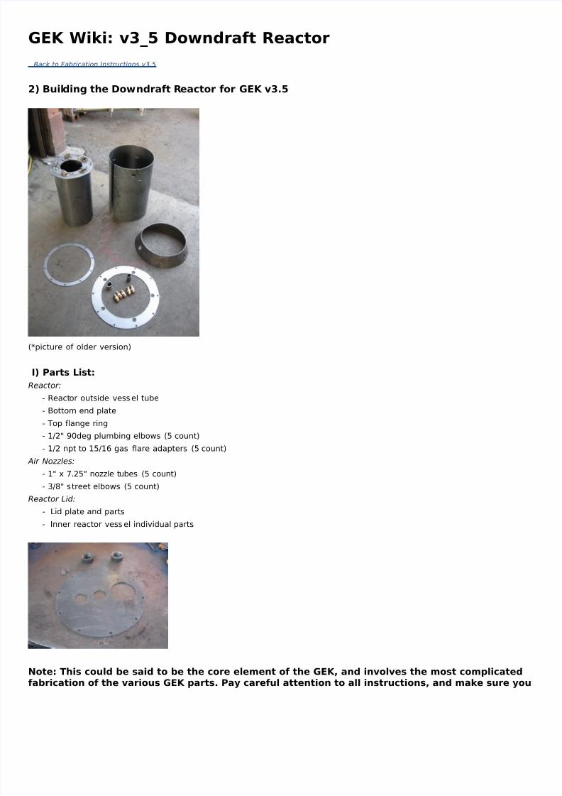
(*picture of older version)
I) Parts List:
Reactor:
- Reactor outside vessel tube
- Bottom end plate
- Top flange ring
- 1/2" 90deg plumbing elbows (5 count)
- 1/2 npt to 15/16 gas flare adapters (5 count)
Air Nozzles:
- 1" x 7.25" nozzle tubes (5 count)
- 3/8" street elbows (5 count)
Reactor Lid:
- Lid plate and parts
- Inner reactor vess el individual parts
Note: This could be said to be the core element of the GEK, and involves the most complicatefabrication of the various GEK parts. Pay careful attention to all instructions, and make sure y
5/8/2018 v3 5+Downdraft+Reactor - slidepdf.com
http://slidepdf.com/reader/full/v3-5downdraftreactor 2/7
complete each step before doing the next one- there are many build order dependencies.
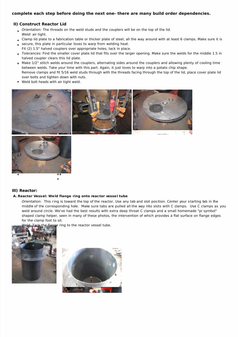
II) Construct Reactor Lid
Orientation: The threads on the weld studs and the couplers will be on the top of the lid.
Weld: air tight.
Clamp lid plate to a fabrication table or thicker plate of steel, all the way around with at least 6 clamps. Make sure i
secure, this plate in particular loves to warp from welding heat.
Fit (2) 1.5" halved couplers over appropriate holes, tack in place.
Tolerances: Find the smaller cover plate lid that fits over the larger opening. Make sure the welds for the middle 1.5
halved coupler clears this lid plate.Make 1/2" stitch welds around the couplers, alternating sides around the couplers and allowing plenty of cooling tim
between welds. Take your time with this part. Again, it just loves to warp into a potato chip shape.
Remove clamps and fit 5/16 weld studs through with the threads facing through the top of the lid, place cover plate
over bolts and tighten down with nuts.
Weld bolt heads with air tight weld.
III) Reactor:
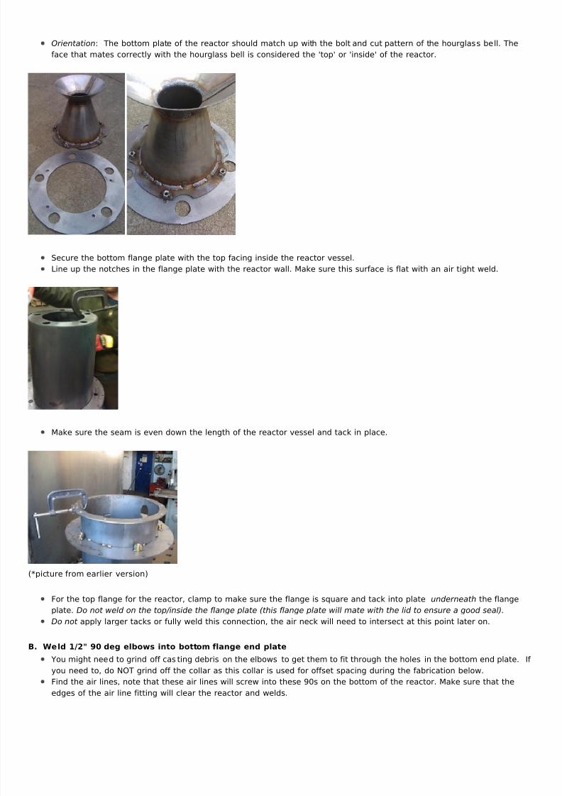
A. Reactor Vessel: Weld flange ring onto reactor vessel tube
Orientation: This r ing is toward the top of the reactor. Use any tab and slot position. Center your starting tab in the
middle of the corres ponding hole. Make sure tabs are pulled all the way into s lots with C clamps. Use C clamps as
weld around circle. We've had the best results with extra deep throat C clamps and a small homemade "pi symbol"
shaped clamp helper, seen in many of these photos, the intervention of which provides a flat surface on flange edg
for the clamp foot to sit.
Weld: Tack the flange ring to the reactor vessel tube.
5/8/2018 v3 5+Downdraft+Reactor - slidepdf.com
http://slidepdf.com/reader/full/v3-5downdraftreactor 3/7
Orientation: The bottom plate of the reactor should match up with the bolt and cut pattern of the hourglass bell. Th
face that mates correctly with the hourglass bell is considered the 'top' or 'inside' of the reactor.
Secure the bottom flange plate with the top facing inside the reactor vessel.
Line up the notches in the flange plate with the reactor wall. Make sure this surface is flat with an air tight weld.
Make sure the seam is even down the length of the reactor vessel and tack in place.
(*picture from earlier version)
For the top flange for the reactor, clamp to make sure the flange is square and tack into plate underneath the flang
plate. Do not weld on the top/inside the flange plate (this flange plate will mate with the lid to ensure a good seal).
Do not apply larger tacks or fully weld this connection, the air neck will need to intersect at this point later on.
B. Weld 1/2" 90 deg elbows into bottom flange end plate
You might need to grind off casting debris on the elbows to get them to fit through the holes in the bottom end plat
you need to, do NOT grind off the collar as this collar is used for offset spacing during the fabrication below.
Find the air lines, note that these air lines will screw into these 90s on the bottom of the reactor. Make sure that th
edges of the air line fitting will clear the reactor and welds.
5/8/2018 v3 5+Downdraft+Reactor - slidepdf.com
http://slidepdf.com/reader/full/v3-5downdraftreactor 4/7
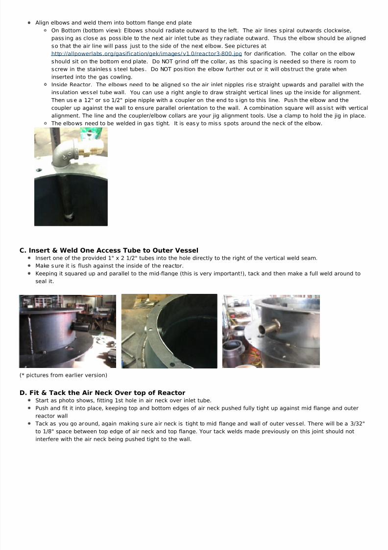
Align elbows and weld them into bottom flange end plate
On Bottom (bottom view): Elbows should radiate outward to the left. The air lines spiral outwards clockwise,
passing as close as possible to the next air inlet tube as they radiate outward. Thus the elbow should be ali
so that the air line will pass just to the side of the next elbow. See pictures at
https://reader004.{domain}/reader004/html5/0412/5acf237d641f0/5acf2382d954f.jpgfor clarification. The collar on the elbow
should sit on the bottom end plate. Do NOT grind off the collar, as this spacing is needed so there is room to
screw in the stainless s teel tubes. Do NOT position the elbow further out or it will obstruct the grate when
inserted into the gas cowling.
Inside Reactor. The elbows need to be aligned so the air inlet nipples ris e straight upwards and parallel with
insulation vess el tube wall. You can use a right angle to draw straight vertical lines up the inside for alignme
Then use a 12" or so 1/2" pipe nipple with a coupler on the end to sign to this line. Push the elbow and the
coupler up against the wall to ensure parallel orientation to the wall. A combination square will assist with ve
alignment. The line and the coupler/elbow collars are your jig alignment tools. Use a clamp to hold the jig in p
The elbows need to be welded in gas tight. It is eas y to miss spots around the neck of the elbow.
C. Insert & Weld One Access Tube to Outer VesselInsert one of the provided 1" x 2 1/2" tubes into the hole directly to the right of the vertical weld seam.
Make sure it is flush against the inside of the reactor.
Keeping it squared up and parallel to the mid-flange (this is very important!), tack and then make a full weld around
seal it.
(* pictures from earlier version)
D. Fit & Tack the Air Neck Over top of Reactor
Start as photo shows, fitting 1st hole in air neck over inlet tube.
Push and fit it into place, keeping top and bottom edges of air neck pushed fully tight up against mid flange and out
reactor wall
Tack as you go around, again making sure air neck is tight to mid flange and wall of outer vessel. There will be a 3/
to 1/8" space between top edge of air neck and top flange. Your tack welds made previously on this joint should no
interfere with the air neck being pushed tight to the wall.
5/8/2018 v3 5+Downdraft+Reactor - slidepdf.com
http://slidepdf.com/reader/full/v3-5downdraftreactor 5/7
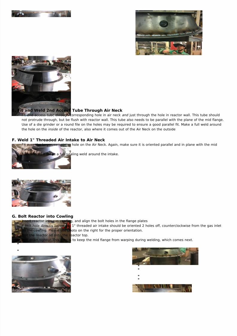
E. Fit and Weld 2nd Access Tube Through Air Neck Fit 2nd access tube through corresponding hole in air neck and just through the hole in reactor wall. This tube shou
not protrude through, but be flush with reactor wall. This tube also needs to be parallel with the plane of the mid fla
Use of a die grinder or a round file on the holes may be required to ensure a good parallel fit. Make a full weld arou
the hole on the inside of the reactor, also where it comes out of the Air Neck on the outside
F. Weld 1" Threaded Air Intake to Air Neck Fit over the larger, remaining hole on the Air Neck. Again, make sure it is oriented parallel and in plane with the mid
flange.
Tack and then make a full sealing weld around the intake.
G. Bolt Reactor into CowlingInsert reactor into gas cowling, and align the bolt holes in the flange plates
A bolt hole directly below the 1" threaded air intake should be oriented 2 holes off, counterclockwise from the gas in
on the cowling. Please see photo on the right for the proper orientation.
Bolt the reactor lid onto the reactor top.Bolt down tightly! This step is to keep the mid flange from warping during welding, which comes next.
5/8/2018 v3 5+Downdraft+Reactor - slidepdf.com
http://slidepdf.com/reader/full/v3-5downdraftreactor 6/7
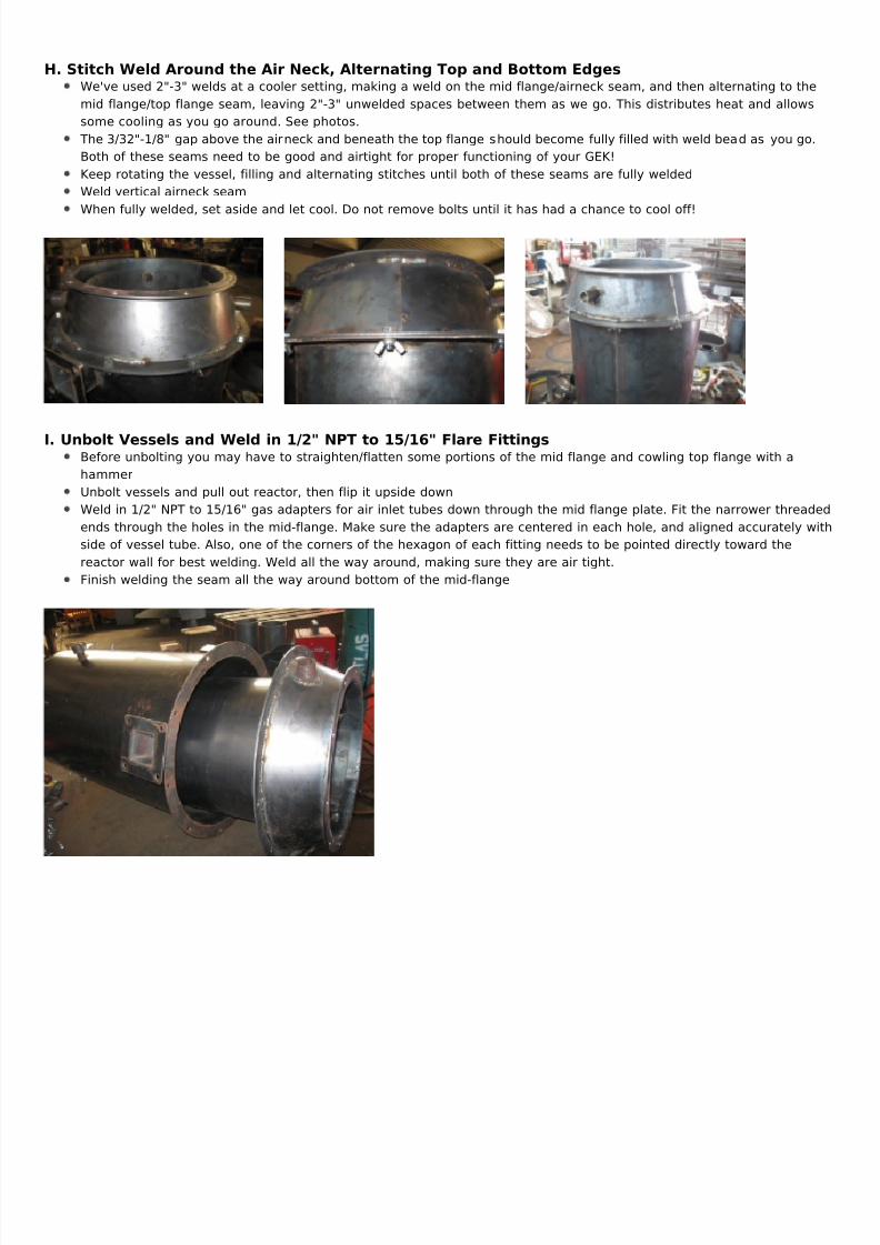
H. Stitch Weld Around the Air Neck, Alternating Top and Bottom EdgesWe've used 2"-3" welds at a cooler setting, making a weld on the mid flange/airneck seam, and then alternating to t
mid flange/top flange seam, leaving 2"-3" unwelded spaces between them as we go. This distributes heat and allow
some cooling as you go around. See photos.
The 3/32"-1/8" gap above the airneck and beneath the top flange should become fully filled with weld bead as you g
Both of these seams need to be good and airtight for proper functioning of your GEK!
Keep rotating the vessel, filling and alternating stitches until both of these seams are fully welded
Weld vertical airneck seam
When fully welded, set aside and let cool. Do not remove bolts until it has had a chance to cool off!
I. Unbolt Vessels and Weld in 1/2" NPT to 15/16" Flare FittingsBefore unbolting you may have to straighten/flatten some portions of the mid flange and cowling top flange with a
hammer
Unbolt vessels and pull out reactor, then flip it upside down
Weld in 1/2" NPT to 15/16" gas adapters for air inlet tubes down through the mid flange plate. Fit the narrower threa
ends through the holes in the mid-flange. Make sure the adapters are centered in each hole, and aligned accurately
side of vessel tube. Also, one of the corners of the hexagon of each fitting needs to be pointed directly toward the
reactor wall for best welding. Weld all the way around, making sure they are air tight.
Finish welding the seam all the way around bottom of the mid-flange
5/8/2018 v3 5+Downdraft+Reactor - slidepdf.com
http://slidepdf.com/reader/full/v3-5downdraftreactor 7/7
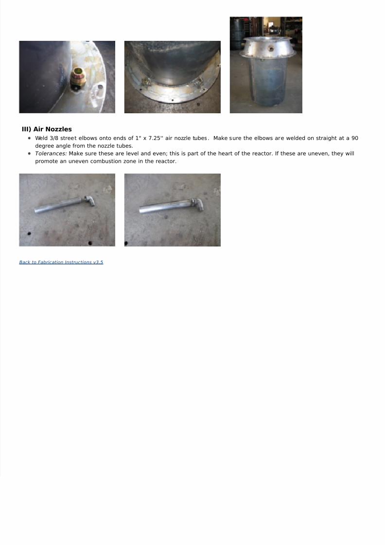
III) Air Nozzles
Weld 3/8 street elbows onto ends of 1" x 7.25'' air nozzle tubes. Make sure the elbows are welded on straight at a
degree angle from the nozzle tubes.
Tolerances: Make sure these are level and even; this is part of the heart of the reactor. If these are uneven, they w
promote an uneven combustion zone in the reactor.
Back to Fabrication Instructions v3.5