v35-s submersible pump instruction manual vada v35-s is a multistage submersible pump designed to...
TRANSCRIPT

V35-SSubmersible Pump Instruction Manual

CONSTRUCTIONPump Body Powder Coated Alloy
Impeller(s) Technopolymer
Diffuser Technopolymer
Diffuser Insert SS 304
Motor Case SS 304
Inlet Flange Technopolymer
Discharge Powder Coated Alloy
Oil Seal Nitrile
Power Cable 10m H07 RN-F
PRODUCT OVERVIEWThe VADA V35-S is a multistage submersible pump designed to provide water from your tank to your garden or house. Because it is submerged, the V35-S operates silently, and takes up no space at ground level.
USAGE LIMITATIONS• Type of liquid: clean water with no suspended solids or
abrasive material• Maximum liquid temperature: 40OC• Maximum submersion depth: 7m
MOTOR• Dry motor with stainless steel casing cooled by pumped
liquid• Level of protection IP 68• Class F insulation• Single phase power supply with capacitor permanently
activated• Thermal protection built into the motor winding• Completely insulated cable connection chamber• Self-lubricating ball bearings• Speed of rotation 2850 rpm• Suitable for continuous use
VADA - V35-S
WARRANTYYou have purchased a quality product from Reece Australia. This product is covered by a 24 month warranty. This warranty covers faults in the product construction, material and assembly. Faulty products will be repaired or exchanged free of charge. Faulty items become our property.This warranty does not include faults caused by• Unsuitable or improper use• Incorrect installation• Normal wear and tear• Inadequate or complete lack of maintenance• Chemical, electrochemical or electrical influences
To the maximum extent permitted by law, Reece excludes all warranties other than those set out above. In the event of a warranty claim, we will replace or repair defective products, or pay for the cost of having defective products repaired or replaced, but will not be liable for any injury to any person, damage to any property, any indirect or consequential loss, or in any other respect.

TABLE OF HYDRAULIC PERFORMANCE
PUMP PERFORMANCE
PUMP DIMENSIONS
ModelNominal power Absorbed
power Voltage Amp µF No. Stages Q
L/min 0 20 40 60 80
HP kW HP kW m3/h 0 1.2 2.4 3.6 4.8
V35-S 0.8 0.65 1.1 0.8 240V~ 4.0A 8 3 Discharge head in metres 32 26 21 16 10
ModelDimensions (mm) Weight
A B C D E F G Outlet Port kg
V35-S 282 86 148 327 222 157 133 1 1/4”M 6
VADA - V35-S
0
5
10
15
20
25
30
35
0 20 40 60 80 100 120
Head
(met
ers)
Flow (litres/minute)
V35-S
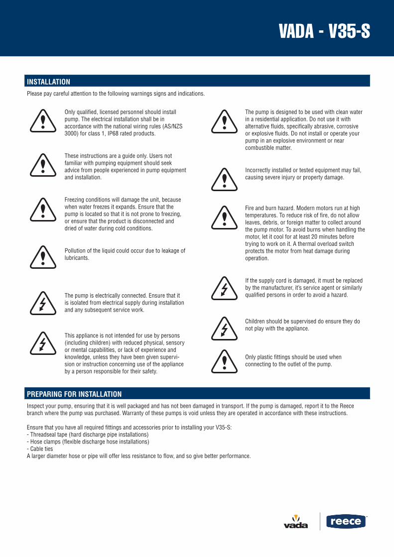
PREPARING FOR INSTALLATIONInspect your pump, ensuring that it is well packaged and has not been damaged in transport. If the pump is damaged, report it to the Reece branch where the pump was purchased. Warranty of these pumps is void unless they are operated in accordance with these instructions.
Ensure that you have all required fittings and accessories prior to installing your V35-S:- Threadseal tape (hard discharge pipe installations)- Hose clamps (flexible discharge hose installations)- Cable tiesA larger diameter hose or pipe will offer less resistance to flow, and so give better performance.
VADA - V35-S
The pump is designed to be used with clean water in a residential application. Do not use it with alternative fluids, specifically abrasive, corrosive or explosive fluids. Do not install or operate your pump in an explosive environment or near combustible matter.
Incorrectly installed or tested equipment may fail, causing severe injury or property damage.
Fire and burn hazard. Modern motors run at high temperatures. To reduce risk of fire, do not allow leaves, debris, or foreign matter to collect around the pump motor. To avoid burns when handling the motor, let it cool for at least 20 minutes before trying to work on it. A thermal overload switch protects the motor from heat damage during operation.
If the supply cord is damaged, it must be replaced by the manufacturer, it’s service agent or similarly qualified persons in order to avoid a hazard.
Children should be supervised do ensure they do not play with the appliance.
Only plastic fittings should be used when connecting to the outlet of the pump.
Only qualified, licensed personnel should install pump. The electrical installation shall be in accordance with the national wiring rules (AS/NZS 3000) for class 1, IP68 rated products.
These instructions are a guide only. Users not familiar with pumping equipment should seek advice from people experienced in pump equipment and installation.
Freezing conditions will damage the unit, because when water freezes it expands. Ensure that the pump is located so that it is not prone to freezing, or ensure that the product is disconnected and dried of water during cold conditions.
Pollution of the liquid could occur due to leakage of lubricants.
The pump is electrically connected. Ensure that it is isolated from electrical supply during installation and any subsequent service work.
This appliance is not intended for use by persons (including children) with reduced physical, sensory or mental capabilities, or lack of experience and knowledge, unless they have been given supervi-sion or instruction concerning use of the appliance by a person responsible for their safety.
INSTALLATIONPlease pay careful attention to the following warnings signs and indications.

GENERAL INSTALLATION1. Fitting an Auto Pressure Control or Mains Water Switch Over DeviceIf you are using a Vada Auto Pressure Control or Vada Rain2Main with your pump, it needs to be mounted externally to the tank in a suitable posi-tion in line with the delivery piping. This can be achieved using a Vada wall mounting bracket. The unit should be mounted vertically in a position which is out of the weather. Depending on the type of plumbing fitting used to connect to the inlet (underside) of the Auto Pressure Control or Rain2Main Device, the unit may not be clamped firmly to the bracket. We recommend a spacer is fitted where necessary.
For further instructions on connecting these devices, please refer to the manual for your unit. Ensure that the power lead remains disconnected until you have completed the installation process.
2. Locating the PumpConnect a nylon rope or a stainless steel cable with a safe working load exceeding 10kg to the handle of the pump.
3. Power SourceArrange for an electrician to install a 10A weatherproof outdoor power point near the pump if there is not one there already. The pump must be supplied by an outlet protected by a residual current device or earth leakage circuit breaker with a maximum rated residual current of 30mA.
4. DischargeIf you are using a hard discharge pipe, thread this on to the outlet of the pump housing. If you are using a flexible discharge hose, use hose clamps to secure this to the fitting provided.
The length and diameter of the discharge hoses/pipes will affect the pressure and flow rate at which your pump operates. Pressure ratings of all components must exceed the maximum pressure of the pump by an appropriate safety factor. All pipe work should be supported independently of the pump.
5. Position PumpLower the pump into the tank using the rope or wire cable. Lower the pump onto a hard level surface that is elevated from the base of the tank. This is to keep the pump inlet above sediments in the bottom of the tank.
VADA - V35-S
ELECTRICAL INSTALLATION
This appliance is not intended for use by persons (including children) with reduced physical, sensory or mental capabilities, or lack of experience and knowledge, unless they have been given supervision or instruction concerning use of the appliance by a person responsible for their safety.
The pump must be supplied by an outlet protected by a residual current device or earth leakage circuit breaker with a maximum rated residual current of 30mA
The pump is supplied with:• A fixed cable featuring a weatherproof IEC socket
If you are installing a Vada Auto Pressure Control or a Vada Rain2Main, connect the IEC socket from the pump to the IEC plug cord on the device. It is advisable to connect the electrical cable(s) to the discharge line at one metre intervals.
Ensuring there are no water traces on the connectors push them firmly into each other to ensure intended splash (water) proof protection. This connection shall be separated again only for service purpose and only after the power supply is removed by unplugging the cord from the socket outlet. The socket outlet shall be in dry and flood free location; preferably do not use extension cords for this very reason and because they can cause voltage drop. Supply voltage outside limits specified in Model Data can cause motor overheat leading to overload tripping, reduced component life or seriously damage pump and voids warranty.
For additional protection, the pump must be supplied from an outlet protected by a residual current device – RCD (also known as an Earth Leakage Circuit breaker – ELCB) with a maximum rated residual current of 30mA.

The pump is designed to be used with clean water in a residential application. Do not use it with alternative fluids, specifically abrasive, corrosive or explosive fluids. Do not install or operate your pump in an explosive enviroment or near combustible matter.
Do not run the V35-S dry, or with the motor exposed (i.e.out of the water) for long periods. This will harm the pumps seal,and overheat the motor.
Liquid may be HOT, release pressure with care before servicing.
The pump operator or owner must be provided with this owner’s manual. This must be read before operation, and followed during operation.
DO NOT RUN PUMP DRYEnsure that your pump is submerged in water before operating.
Pump should only be serviced by qualified personnel. For best results, use only genuine ser-vice parts. Be sure to prime pump before starting.
To avoid dangerous or fatal electrical shock hazard, turn OFF power to motor and remove plug from power outlet before working on pump or motor.
OPERATION
SERVICE AND MAINTENANCE
GENERAL CARE AND MAINTENANCEUnder normal conditions V35-S pumps do not need any type of maintenance. In order to avoid possible failures, it is advisable to periodically check the pressure supplied and current absorption. A decrease in pressure is a symptom of wear. An increase in current absorption is a sign of abnormal mechanical friction in the pump and/or motor.
If the pump is not going to be used for long periods of time it should be emptied completely, rinsed with clean water and put in a dry place.
START-UP/OPERATIONOpen all valves in the suction and discharge lines. When the power is turned on, the pump will start to pump water. Without an Auto Pressure Control or Mains Water Switch-Over Device, the pump will continue to operate until the power is switched off.
Most applications will incorporate an Auto Pressure Control or Mains Water Switch-Over Device which will stop the pump as soon as it has pressurised the system it is connected to. For instructions on operating your pump with one of these devices, please refer to the manual that came with your unit.
The system is now ready for use. If no water is delivered, check the troubleshooting section.
VADA - V35-S

TROUBLE SHOOTING GUIDE
Symptom Cause Remedy
Pump doesn’t start No power supply Ensure that the socket outlet where the pump is connected to is switched on.
Check fuses and/or circuit breakers and RCD.
Pump is blocked Disconnect the pump from the power outlet, and check the pump housing and discharge for foreign matter.
No water from pump Blockages in the pump or discharge Disconnect the pump from the power outlet, and check the pump housing and discharge for foreign matter.
Excessive lift Ensure that the height that youare trying to lift water is within thepump’s capacity. A larger pumpmay be required.
Not enough water in the tank to pump Wait until there is more water in thetank. Ensure that float switch isoperating freely.
Pump runs intermittently:Thermal protection inside the pump is tripping and resetting
The pump is not completely submerged Ensure pump is covered with water
Water temperature is too high Ensure that water temperature limitsare observed.
VADA - V35-S

Disclaimer:Products in this specification manual must by regulation be installed by licensed and registered trade people. The manufacturer/distributorreserves the right to vary specifications or delete models from their range without prior notification. Dimensions and set-outs listed arecorrect at time of publication however the manufacturer/distributor takes no responsibility for printing errors.