vac d500 electro-pneumatic positioner compact, well-proven ... · if the electrical supply power...
TRANSCRIPT

VAC D500 Electro-Pneumatic Positioner
Compact, well-proven, and
High air capacity Diagnostics capability Resistant to overpressure Robust and environm entally ruggedized Easy to commission
Approvals for explosion protection — ATEX — IECEx — FM / CSA — GOST For SIL2 safety loop Extended diagnostics
Change from one to two columns

VAC D500Electro-Pneumatic Positioner
2 D500
Brief description
The VAC D500 is an electronically con�gurable positioner with communication capabilities designed for mounting to pneumatic linear or part-turn actuators. It features a small and compact design, a modular construction, and an excellent cost-performance ratio. Fully automatic determination of the control parameters and adaptation to the �nal control element yield considerable time savings and an optimal control behavior. Pneumatics An I/P module with subsequent pneumatic ampli�er is used to control the pneumatic actuator. The well-proven I/P module proportionally converts the permanent electrical setpoint signal from the CPU into a pneumatic signal used to adjust a 3/3-way valve. The air �ow for pressurizing or depressurizing the actuator is continuously adjusted. As a result, excellent control is achieved. When reaching the setpoint, the 3/3-way valve is closed in center position to minimize the air consumption. Four di�erent pneumatics versions are available: for single-acting or double-acting actuators, each with “fail-safe” or “fail-freeze” function.
“Fail-safe” function If the electrical supply power fails, the positioner output 1 is depressurized, and the pneumatic actuator’s return spring moves the valve to the de�ned safe position. In case of a double-acting actuator the second output 2 is additionally pressurized. “Fail-freeze” function If the electrical supply power fails, the positioner output 1 (and 2, if applicable) is closed and the pneumatic actuator stops (“freezes”) the valve in the current position. If the compressed air supply power fails, the positioner depressurizes the actuator.
Operation The positioner has a built-in LCD-indicator with a multi-line LCD display and 4 pushbuttons for commissioning, con�guration, and monitoring during live operation. Alternatively, the appropriate DTM/EDD can be used via the available communication interface. Communication The positioner supports HART5 and HART7 communication. Inputs / Outputs In addition to its input for the analog position setpoint, the positioner is equipped with a digital input which can be used to activate control system functions in the device. A digital output allows you to output collective alarms or fault messages.
Modular design The basic model can be enhanced at any time by retro�tting optional equipment. Option modules for analog and digital feedback, an emergency shutdown module, and pressure sensors for valve diagnostics can be installed. A module for a universal analog input can also be installed to which any device supplying a 4 … 20 mA signal can be connected. Additionally, a mechanical position indicator, proximity switches or 24 V microswitches are available for indicating the position independently of the mother board function. Diagnostics The positioner has three optional pressure sensors which can be used for reliable diagnostics of the valve, the pneumatic drive, and the positioner.
Change from two to one column
D500 3
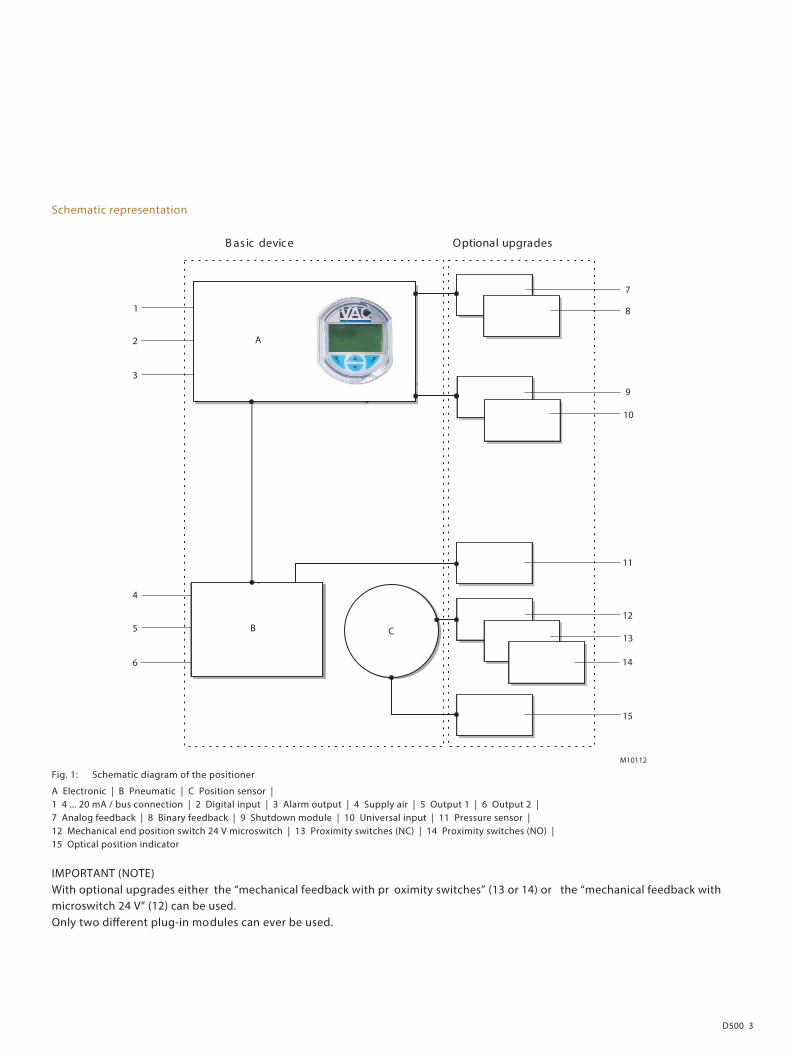
Schematic representation
sedargpu lanoitpO ecived cisaB
M10112
A
B C
2
9
11
12
13
14
15
3
4
5
1
6
7
8
10
Fig. 1: Schematic diagram of the positioner
A Electronic | B Pneumatic | C Position sensor | 1 4 ... 20 mA / bus connection | 2 Digital input | 3 Alarm output | 4 Supply air | 5 Output 1 | 6 Output 2 | 7 Analog feedback | 8 Binary feedback | 9 Shutdown module | 10 Universal input | 11 Pressure sensor | 12 Mechanical end position switch 24 V microswitch | 13 Proximity switches (NC) | 14 Proximity switches (NO) | 15 Optical position indicator kllkl
IMPORTANT (NOTE) With optional upgrades either the “mechanical feedback with pr oximity switches” (13 or 14) or the “mechanical feedback with microswitch 24 V” (12) can be used. Only two di�erent plug-in modules can ever be used.
VAC D500 Electro-Pneumatic Positioner
4 D500
Change from one to two columns
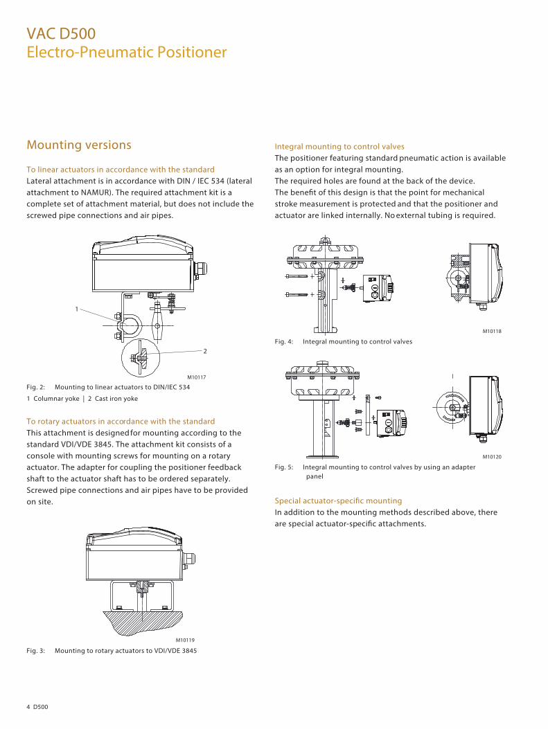
Mounting versions
To linear actuators in accordance with the standard Lateral attachment is in accordance with DIN / IEC 534 (lateral attachment to NAMUR). The required attachment kit is a complete set of attachment material, but does not include the screwed pipe connections and air pipes.
M10117
1
2
Fig. 2: Mounting to linear actuators to DIN/IEC 534
1 Columnar yoke | 2 Cast iron yoke
To rotary actuators in accordance with the standard This attachment is designed for mounting according to the standard VDI/VDE 3845. The attachment kit consists of a console with mounting screws for mounting on a rotary actuator. The adapter for coupling the positioner feedback shaft to the actuator shaft has to be ordered separately. Screwed pipe connections and air pipes have to be provided on site.
M10119 Fig. 3: Mounting to rotary actuators to VDI/VDE 3845
Integral mounting to control valves The positioner featuring standard pneumatic action is available as an option for integral mounting. The required holes are found at the back of the device. The bene�t of this design is that the point for mechanical stroke measurement is protected and that the positioner and actuator are linked internally. No external tubing is required.
M10118 Fig. 4: Integral mounting to control valves
M10120 Fig. 5: Integral mounting to control valves by using an adapter
panel
Special actuator-speci�c mounting In addition to the mounting methods described above, there are special actuator-speci�c attachments.
Change from two to one column
D500 5
Change from one to two columns
Device parameters
General remarks Microprocessor-based position control in the positioner optimizes control. The positioner features high-precision control functions and high operational reliability. Due to their elaborate structure and easy accessibility, the device parameters can be quickly adapted to the respective application. The total range of parameters includes: — Operating parameters — Adjustment parameters — Monitoring parameters — Diagnostics parameters — Maintenance parameters Operating parameters The following operating parameters can be set manually if required: Setpoint signal 0 ... 100 % freely selectable for split-range operation For 4 ... 20 mA and HART version: — Signal min. 4 mA, max. signal 20 mA (0 ... 100 %) — Min. range 20 % (3.2 mA) — Recommended range > 50 % (8.0 mA) Action (setpoint signal) Increasing: Position value 0 ... 100 % = direction 0 ... 100 % Decreasing: Setpoint signal 100 ... 0 % = direction 0 ... 100 % Characteristic curve (trave l = f {setpoint signal}) Linear, equal percentage 1:25 or 1:50 or 25:1 or 50:1 or freely con�gurable with 20 reference points. Travel limit The positioning travel, i.e. the stroke or angle of rotation, can be reduced as required within the full range of 0 ... 100 %, provided that a minimum value of 20% is observed.
Shut-o� function This parameter can be set separately for each end position. When the respective con�gured limit value is exceeded, the shut-o� function causes immediate travel of the actuator until reaching the set end position. When the shut-o� value is set to “0”, the position is further controlled, even in the respective end position. Travel time prolongation This function can be used to increase the max. travel time for full travel. This time parameter can be set separately for each direction. Switching points for the position
You can use these parameters to de�ne two position limits for signaling (see option “Module for digital position feedback”). Alarm output The alarms generated in the positioner can be polled via the digital output as a collective alarm. The desired information can be selected via the LCD display or remotely via the con�guration program. The output can be set to “active high” or “active low”, as required. Digital input For the digital input, one of the following safety options can be selected. You may use the LCD display or con�guration program to select an option. — No function (default) — Move to position substitute value (freely selectable) — Start "Partial Stroke Test" — Ventilate output 1, evacuate output 2 — Ventilate output 2, evacuate output 1 — Service required — Move to 0 % position — Move to 100 % position — Hold previous position — Disable local con�guration — Disable local con�guration and operation — Disable all access (no local or remote access via a PC) The selected function is activated once the 24 V DC signal is no longer applied (< 11 V DC).

VAC D500 Electro-Pneumatic Positioner
6 D500
Adjustment parameters The positioner has a special function for automatic adjustment of the parameters. Additionally, the control parameters can be set automatically (in adaptive control mode) or manually to optimally adapt them to the process requirements. Zone Upon reaching this value, the position is readjusted more slowly until the dead band is reached. Dead band (sensitivity) When reaching the dead band, the position is held. Display 0 ... 100 % Adjusting the display (0 ... 100 %) according to the direction of action for opening or closing the actuator.
Diagnostics Various functions for permanent operational monitoring are implemented in the PositionMaster EDP300 operating program. The following states will be detected and indicated, e. g.: — Setpoint signal out of range 0 ... 100 % or 4 ... 20 mA — Position out of the adjusted range — Positioning time-out (adjustable time parameter) — Position controller inactive — Counter limit values exceeded (can be set via DTM/EDD)
LCD display The LCD indicator has a cover to protect against unauthorized operation. Commissioning the positioner is especially easy. Autoadjust is triggered by pressing just a few pushbuttons. Detailed con guration knowledge is not necessary in order to start the device. Depending on the selected actuator type (linear or rotary), the displayed zero position is automatically adapted. Besides this standard function, a customized “Autoadjust” function is available. The function is launched either via the LCD display or HART communication.
M10125 Fig. 6: Open positioner with view of LCD indicator
The built-in LCD indicator with four pushbuttons supports the following functions: — Operational monitoring — Manual intervention during live operation — Device uration — Fully automatic commissioning — Display of diagnostic messages
M10126 Fig. 7: LCD indicator with pushbuttons and LCD display
A menu-controlled co gurat ion is available via the pushbuttons on the device.

D500 7
The multi-line LCD indicator is permanently updated and adapted during operation to provide the user with optional information as relevant. During control operation (control with or without adaptation) the following data can be called up by pressing the pushbuttons brie�y: — Position Pos [%] — Position Pos [°] — Setpoint SP [%] — Setpoint SP [mA] — Control deviation DEV [%] — Electronics temperature [°C, °F, °R, K] — Supply pressure PIN [unit] — Pressure output 1 PY1 [unit] — Pressure output 2 PY2 [unit] — Di�erential pressure DP [unit] — Universal input value UIN [unit]
— Malfunctions, alarms, messages The possible reason is also displayed, along with the recommended remedial action. In the event of an error, a message consisting of an icon and text (e.g., electronics) appears at the bottom of the process display. The text displayed provides information about the area in which the error has occurred. The error messages are divided into four groups in accordance with the NAMUR classi�cation scheme:
Symbol Description
Error / Failure
Functional check
Out of speci�cation
Maintenance required
(The group assignment can only be changed using a DTM or EDD.)
Additionally, the error messages are divided into the following areas:
Area Description
Actuator Diagnostics messages a�ecting the valve or the
pneumatic actuator
Operation Diagnostics messages a�ecting the operation of
the positioner
Process Diagnostics messages relating to the process and
displaying problems or states
Sensor Alarms informing of problems a�ecting the reading
of the valve position
Electronic Displays errors in the device electronics
Con�guration Detects if the positioner con�guration is missing or
faulty
Histograms recording — Positioning time-outs — Valve movements — Valve strokes — Most used valve position — Universal input Access to extended monitoring parameters is possible via HART communication, the DTM, and the EDD.
The diagnostics parameters in the operating program provide information about the operating conditions of the actuator. For example: — Dead band time limit — Leakage detection — Temperature monitoring — Stiction detection — Sliding friction detection — Hysteresis — Valve seat wear From this information the operator can derive what maintenance work is required, and when.
?

VAC D500 Electro-Pneumatic Positioner
8 D500
Diagnostics with DTM Access to extended monitoring parameters is possible via HART communication, in particular the DTM (reduced functions only with the EDD). Butter�y diagnostics The trend (which relates to a number of relevant positioner parameter values) can be used to draw conclusions about the stiction and friction of a valve with a view to enabling preventive maintenance. If the diagnostic parameters have changed, a triangle is displayed in signal color. The color and size of this triangle represent the direction and scope of the change.
M10114 Fig. 8: Example for increased friction
Online trend archive The online trend archive does not merely indicate the current setpoint and actual value, but also the associated patterns, which can stretch back over a matter of hours. When you start the online trend archive, the saved data is read out and transmitted at such a high transmission rate (100 ms via HART) that the latest data is displayed in next to no time.
M10115 Fig. 9: Example for online trend archive
Event history Up to 100 events are saved in the event history in the device. The time each event occurred is also displayed, along with a suggested approach to solving the problem. The limit values for (pre-)alarms, e.g. a friction alarm, can be set.
M10116 Fig. 10: Example event history
D500 9
Valve signature (only with pressure option) When the valve signature starts , the entire valve operating range is covered for the "open and closed directions". High-resolution plots are generated for the pressure patterns at the diagnostic pressure sensors. In addition, the signal waveform for the universal input is recorded. Once the signature has expired, the parameters selected by the user are loaded from the device and displayed. Depending on the quantity of data selected, it may take several minutes to transfer all the parameter values. Up to 5 valve signatures can be saved in the device; these can be compared so that valve diagnostics can be performed for the purpose of preventive maintenance.
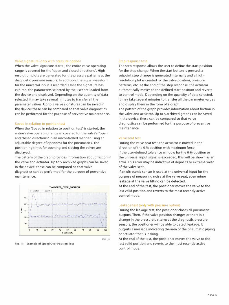
Speed in relation to position test When the "Speed in relation to position test" is started, the entire valve operating range is covered for the valve's "open and closed directions" in an uncontrolled manner using an adjustable degree of openness for the pneumatics. The positioning times for opening and closing the valves are displayed. The pattern of the graph provides information about friction in the valve and actuator. Up to 5 archived graphs can be saved in the device; these can be compared so that valve diagnostics can be performed for the purpose of preventive maintenance.
Fig. 11: Example of Speed Over Position Test
Step response test The step response allows the user to de�ne the start position for the step change. When the start button is pressed, a setpoint step change is generated internally and a high-resolution plot is created for the valve position, pressure patterns, etc. At the end of the step response, the actuator automatically moves to the de�ned start position and reverts to control mode. Depending on the quantity of data selected, it may take several minutes to transfer all the parameter values and display them in the form of a graph. The pattern of the graph provides information about friction in the valve and actuator. Up to 5 archived graphs can be saved in the device; these can be compared so that valve diagnostics can be performed for the purpose of preventive maintenance.
Valve seat test During the valve seat test, the actuator is moved in the direction of the 0 % position with maximum force. If the user-de�ned tolerance window for the 0 % position or the universal input signal is exceeded, this will be shown as an error. This error may be indicative of deposits or extreme wear of the valve seat. If an ultrasonic sensor is used at the universal input for the purpose of measuring noise at the valve seat, even minor leakage at the valve �tting can be detected. At the end of the test, the positioner moves the valve to the last valid position and reverts to the most recently active control mode. Leakage test (only with pressure option) During the leakage test, the positioner closes all pneumatic outputs. Then, if the valve position changes or there is a change in the pressure patterns at the diagnostic pressure sensors, the positioner will be able to detect leakage. It outputs a message indicating the area of the pneumatic piping or actuator that is leaking. At the end of the test, the positioner moves the valve to the last valid position and reverts to the most recently active control mode.
M10121

VAC D500 Electro-Pneumatic Positioner
10 D500
Partial Stroke Test The Partial Stroke Test is used to check the function of the safe position of ESD (emergency shutdown) valves. The test can be started both locally on the device, time-controlled or using the DTM. The positioner evacuates output 1 until the position change de�ned in advance occurs. If this does not happen within the set time, an alarm can be output. This helps prevent unexpected failures of the valve. At the end of the test, the positioner moves the valve to the last valid position and reverts to the most recently active control mode. There are two separate parameters available for reducing the speed at which the valve moves in the corresponding direction.
Drag indicator This diagram shows the minimum, maximum, and average values for a selectable parameter in 3 di�erent intervals, which are o�set in relation to one another. The drag indicator trend, which is plotted against time, makes it possible to plan preventive action so that a failure in terms of the valves and �ttings can be avoided.
Trend histogram This histogram shows, for example, the position range of the valve within which control is most frequently performed. The parameters to be displayed can be selected by the user. This graph can be used, for example, to determine the most commonly used valve position so that the valve design can be evaluated. The friction within a valve range can be determined on the basis of the di�erential pressure, dead band time limit alarms, etc.
M10122 Fig. 12: Example trend histogram
Trend diagram This diagram indicates in which valve positioning range the greatest control deviation has occurred. This allows you to derive the valve friction, actuator size or supply air pressure.
D500 11
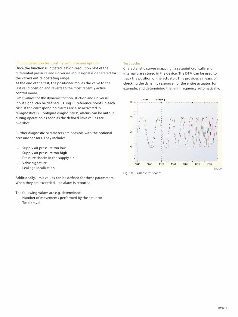
Friction detection test (onl y with pressure option) Once the function is initiated, a high-resolution plot of the di�erential pressure and universal input signal is generated for the valve's entire operating range. At the end of the test, the positioner moves the valve to the last valid position and reverts to the most recently active control mode. Limit values for the dynamic friction, stiction and universal input signal can be de�ned, us ing 11 reference points in each case. If the corresponding alarms are also activated in "Diagnostics -> Con�gure diagno stics", alarms can be output during operation as soon as the de�ned limit values are overshot. Further diagnostic parameters are possible with the optional pressure sensors. They include: — Supply air pressure too low — Supply air pressure too high — Pressure shocks in the supply air — Valve signature — Leakage localization Additionally, limit values can be de�ned for these parameters. When they are exceeded, an alarm is reported. The following values are e.g. determined: — Number of movements performed by the actuator — Total travel
Test cycles Characteristic curves mapping a setpoint cyclically and internally are stored in the device. The DTM can be used to track the position of the actuator. This provides a means of checking the dynamic response of the entire actuator, for example, and determining the limit frequency automatically.
M10127 Fig. 13: Example test cycles
VAC D500 Electro-Pneumatic Positioner
12 D500
Communication
DTM The DTM (Device Type Manager) for the positioner VAC D500 is based on FDT/DTM technology (FDT 1.2/1.2.1) and can be either integrated into a control system or loaded on a PC with DAT200 Asset Vision Basic. This allows you to work with the same user interface in the commissioning phase, during operation, and for service tasks involving monitoring the device, setting parameters, and reading out data. Communication is based on the HART protocol. Reading data out from the device has no e�ect on active operation. Newly set parameters are saved in the non-volatile memory directly upon download to the device, and become active immediately.
EDD The EDD (Electronic Device Description) is used to read and modify simple device parameters on handheld terminals or in the vicinity of the system.
Change from two to one column
D500 13
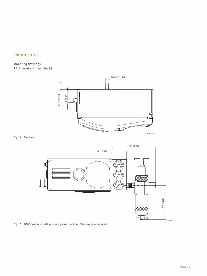
Dimensions
Mounting drawings All dimensions in mm (inch)
M10529
)75.0(5,41
)40.0(1
Ø 8 (0.31) h9
Fig. 14: Top view
M10528
40 (1.57)
120 (4.72)
)28.3(79
Fig. 15: D500 positioner with pressure gauge block and �lter regulator mounted
VAC D500 Electro-Pneumatic Positioner
14 D500
M10524
104,5 (4.11)
60 (2.36)
33,5 (1.32)
23 (0.91)
58 (2.28)
50 (1.97)
45°
)89.0(52
)80.0(2
)82.0(7
)65.2(56
)79.1(05
) 90. 4(401
206 (8.11)
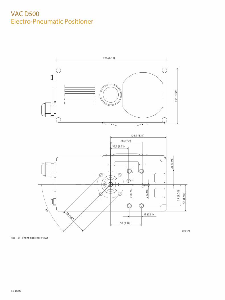
Fig. 16: Front and rear views

D500 15
M10530
14,5(0.57)
1,8(0.07)
115,5
44(1.73)
28(1
.10)
10(0.39)
M5
28(1
.10)
14(0
.55)
28,5
(1.1
2)
2(0
.07)
Fig. 17: Side view (from left to right)
Change from one to two columns
M10134
)59.2(57
30 / 53(1.18 / 2.09)
Fig. 18: Mounting to linear actuators to DIN/IEC 534
M10135
*B
A*
57-
54)59.2
-77.1(
)89.0(52
Fig. 19: Mounting to rotary actuators to VDI/VDE 3845
*) Dimensions A and B are dependent on the rotary actuator
Change from two to one column
VAC D500 Electro-Pneumatic Positioner
16 D500
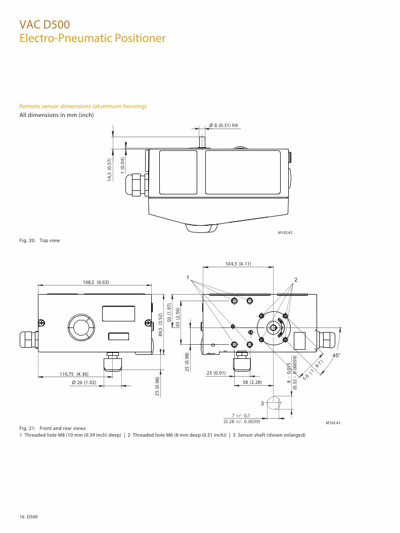
Remote sensor dimensions (aluminum housing)
All dimensions in mm (inch)
Fig. 20: Top view
Fig. 21: Front and rear views 1 Threaded hole M8 (10 mm (0.39 inch) deep) | 2 Threaded hole M6 (8 mm deep (0.31 inch)) | 3 Sensor shaft (shown enlarged)
M102 42
14,5
(0.5
7)
1 (0
.04)
Ø 8 (0.31) h9
M102 43
25 (0
.98)
50 (1
.97)
65 (2
.56)
104,5 (4. 11)
23 (0.91)
7 +/- 0,10.0039)(0.28 +/-
8 -
0,01
5(0
.32
- 0.
0005
9)
58 (2.28)5 0
( 1 . 9 7 )
110,75 (4. 36)
Ø 26 (1.02)
0(52
.98)
89,5
(3.5
2)
168,5 (6.63)
45°
1 2
3
D500 17
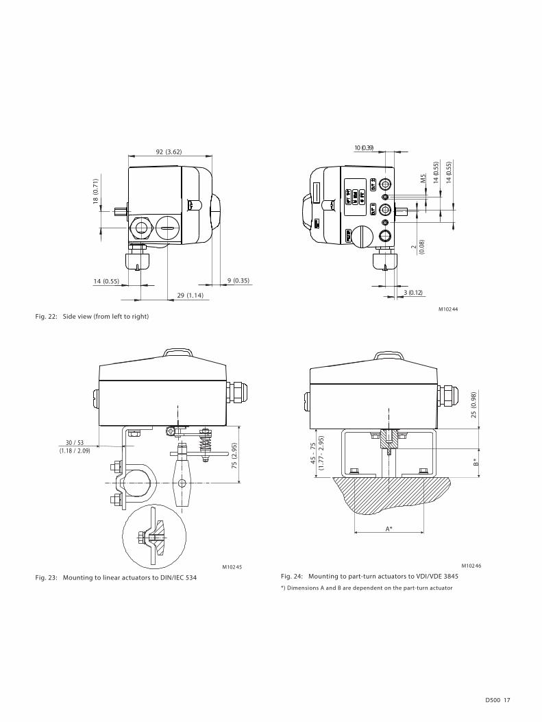
Fig. 22: Side view (from left to right)
Change from one to two columns
M102 45
75 (2
.95)30 / 53
(1.18 / 2.09)
Fig. 23: Mounting to linear actuators to DIN/IEC 534
M102 46
B*
A*
45 -
75(1
.77
- 2.
95)
25 (0
.98)
Fig. 24: Mounting to part-turn actuators to VDI/VDE 3845
*) Dimensions A and B are dependent on the part-turn actuator
Change from two to one column
M102 44
14 (0.55)
29 (1.14)
18 (0
.71)
92 (3.62)
9 (0.35)
140(
.)55
140(
.)55
2(0
.08)
3 (0.12)
10 (0.39)
M5

VAC D500 Electro-Pneumatic Positioner
18 D500
Electrical connections
VAC D500 with remote sensor The VAC D500 version with remote sensor includes an adjusted unit with two housings. Housing 1 (D500 control unit) contains the electronics and pneumatics along with the following options (where applicable): • Analog position feedback • Digital position feedback • Shutdown module • Universal input Housing 2 (D500 remote sensor) contains the position sensor and is suitable for mounting on linear or part-turn actuators. The following options can be installed if required: • Optical position indicator • Mechanical feedback contacts (proximity switch or microswitch design). The two housings can be or are connected to a shielded 3-wire cable. The maximum cable length is 10 m. For Housing 1 (control unit) an attachment kit is available for pipe and wall mounting (see Accessories).
M10830
2 1 7 6 5
3 4
8
Fig. 25: D500 control uni t with remote sensor 1 Housing 1 (control unit) | 2 Setpoint signal | 3 Connection cable | 4 Housing 2 (remote sensor) | 5 Pneumatic ou tput 2 | 6 Pneumatic output 1 | 7 Supply air | 8 Pneumatic drive

D500 19
Optionally, both housings of the “D500 stainless steel remote sensor” design are available in stainless steel. The housing dimensions are identical in this case - and the attachment kits are suitable for all versions.
M10831
Remote - Sensor
2 1 7 6 5
3 4
8
Fig. 26: D500 control unit made of stainless steel with D500 remote sensor made of stainless steel 1 Housing 1 (control unit) | 2 Setpoint | 3 Connection cable | 4 Housing 2 (remote sensor) | 5 Pneumatic output 2 | 6 Pneumatic output 1 | 7 Supply air | 8 Pneumatic drive
M108325 61 2 3 4
Fig. 27: Electrical connection 1 D500 control unit | 2 Remote sensor connection cable no. 3 | 3 Remote sensor connection cable no. 2 | 4 Remote sensor connection cable no. 1 | 5 Shielding | 6 D500 remote sensor

VAC D500 Electro-Pneumatic Positioner
20 D500
VAC D500 for external remote sensor
In the VAC D500 design for remote sensor, the positioner is supplied without position detection. The housing (D500 control unit) contains the electronics and pneumatics along with the following options (where applicable): • Analog position feedback • Digital position feedback • Shutdown module • Universal input The D500 for remote sensor can be connected to any position sensor (4 … 80 kohms). The length of the shielded 3-core cable must be a maximum of 10 m. The installation and commissioning is carried out according to the respective chapters in the operating instructions. For the housing (D500 control unit) an attachment kit is available for pipe and wall mounting. (See Accessories).
M10833
2 1 7 6 5
3 4
8
Fig. 28: D500 control unit for remote sensor 1 Housing (control Unit) | 2 Setpoint signal | 3 Connection cable | 4 External remote sensor | 5 Pneumatic output 2 | 6 Pneumatic output 1 | 7 Supply air | 8 Pneumatic drive
M1083 45 61 2 3 4
Fig. 29: Electrical connection 1 D500 control unit | 2 Remote sensor connection cable No. 3 | 3 Remote sensor connection cable No. 2 | 4 Remote sensor connecting cable no. 1 | 5 Shielding | 6 External remote sensor

D500 21
Terminal connection diagrams
M10835
+11 -12 +81 -82 +83 -84 +51 1-52 2
AD
+41 3-42 +31 -32 +85 +21-86 -222
D V 4C
(20
... V 30
V)
4 ...
20
mA
< = L1
> = H ;
Am
2 m
A
5 ..
. 30
V D
CL
= <
1 m
A; H
= >
2 m
A
5...
30V
DC
4 kO
hm ..
. 80
kO
hm
L =
< 1
mA
; H =
>2
mA
5 ..
. 30
V D
C
24 V
DC
(12
... 3
0 V
)
4 ...
20
Am
AI DI DO SW 2 SW 1 AO UAI
A
4 ...
20
Am
10 ..
. 30
D V C
1 2 3 4 5 6 7 8
B
Fig. 30: Connection diagram of the D500 control unit A Basic device | B Options 1 Setpoint signal | 2 Digital input | 3 Digital output | 4 Digital feedback | 5 Analog feedback | 6 Emergency shutdown module | 7 Universal input | 8 Remote sensor
M10836
+51 -52 +41 -42
< = L1
> = H ;
Am
2 m
A
5 ..
. 11
D V C
Limit 1 Limit 2
< = L1
> = H ;
Am
2 m
A
5 ...
11
D V C
1 2 3 51 52 5341 42 43
.xam
24 V
.xam
2 A
Limit 1 Limit 2
A
1
Position Sensor
2 3
B
Fig. 31: Connection diagram to the D500 remote sensor A Basic device | B Options 1 D500 control unit | 2 Proximity switches | 3 Microswitch

VAC D500 Electro-Pneumatic Positioner
22 D500
Change from one to two columns
Technical Data
Inputs
Two-wire technology
Nominal range 4 ... 20 mA
Limit values Max.: 50 mA (overload)
Min.: 3.6 mA
Start � 3.8 mA
Load voltage at 20 mA 9.7 V
Impedance at 20 mA 485 Ω
Digital input
Control voltage 0 … 5 V DC (switching state logical "0")
11 … 30 V DC (switching state logical "1")
Am 4 .xam tnerruC
Outputs
Digital output (control circuit to DIN 19234/NAMUR)
Supply voltage 5 ... 30 V DC
Switching state logical "0": Current > 0.35 mA … < 1.2 mA
"1": Current > 2.1 mA
E�ective direction
(con�gurable)
normally logical "0" or logical "1"
Cable connections
Electrical connections
4 … 20 mA input Screw terminals max. 2.5 mm 2 (AWG 14)
Options Screw terminals max. 1.0 mm 2 (AWG 18)
Cable entry 2 threaded bores 1/2-14 NPT/M20 x 1.5
(cable gland/pipe plug optional)
cross section
Rigid / �exible wires 0.14 ... 2.5 mm 2 (AWG 26 ... AWG 14)
Flexible with wire end
sleeve
0.25 ... 2.5 mm 2 (AWG 23 ... AWG 14)
Flexible with wire end
sleeve no plastic sleeve
0.25 ... 1.5 mm 2 (AWG 23 ... AWG 17)
Flexible with wire end
sleeve with plastic sleeve
0.14 ... 0.75 mm 2 (AWG 26 ... AWG 20)
Multi-wire connection capacity (2 wires of the same cross section)
Rigid / �exible wires 0.14 ... 0.75 mm 2 (AWG 26 ... AWG 20)
Flexible with wire end
sleeve no plastic sleeve
0.25 ... 0.75 mm 2 (AWG 23 ... AWG 20)
Flexible with wire end
sleeve with plastic sleeve
0.5 ... 1.5 mm 2 (AWG 21 ... AWG 17)
Options
cross section
Rigid / �exible wires 0.14 ... 1.5 mm 2 (AWG 26 ... AWG 17)
Flexible with wire end
sleeve no plastic sleeve
0.25 ... 1.5 mm 2 (AWG 23 ... AWG 17)
Flexible with wire end
sleeve with plastic sleeve
0.25 ... 1.5 mm 2 (AWG 23 ... AWG 17)
Multi-wire connection capacity (2 wires of the same cross section)
Rigid / �exible wires 0.14 ... 0.75 mm 2 (AWG 26 ... AWG 20)
Flexible with wire end
sleeve no plastic sleeve
0.25 ... 0.5 mm 2 (AWG 23 ... AWG 22)
Flexible with wire end
sleeve with plastic sleeve
0.5 ... 1 mm 2 (AWG 21 ... AWG 18)
D500 23
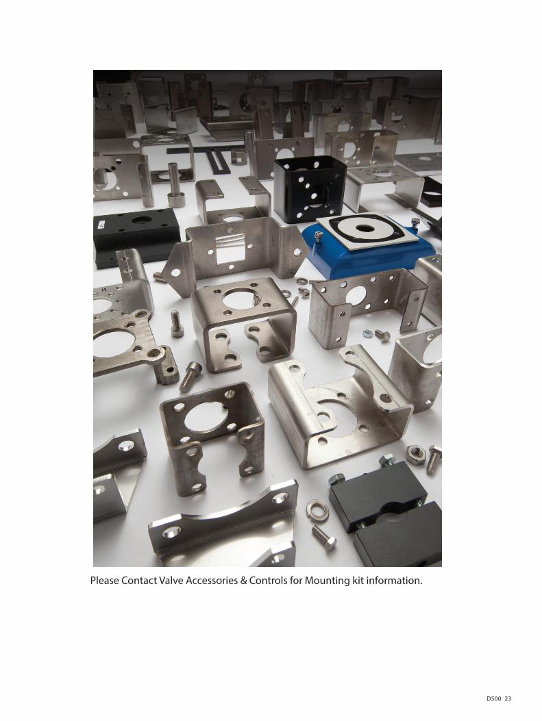
Please Contact Valve Accessories & Controls for Mounting kit information.
VAC D500 Electro-Pneumatic Positioner
24 D500
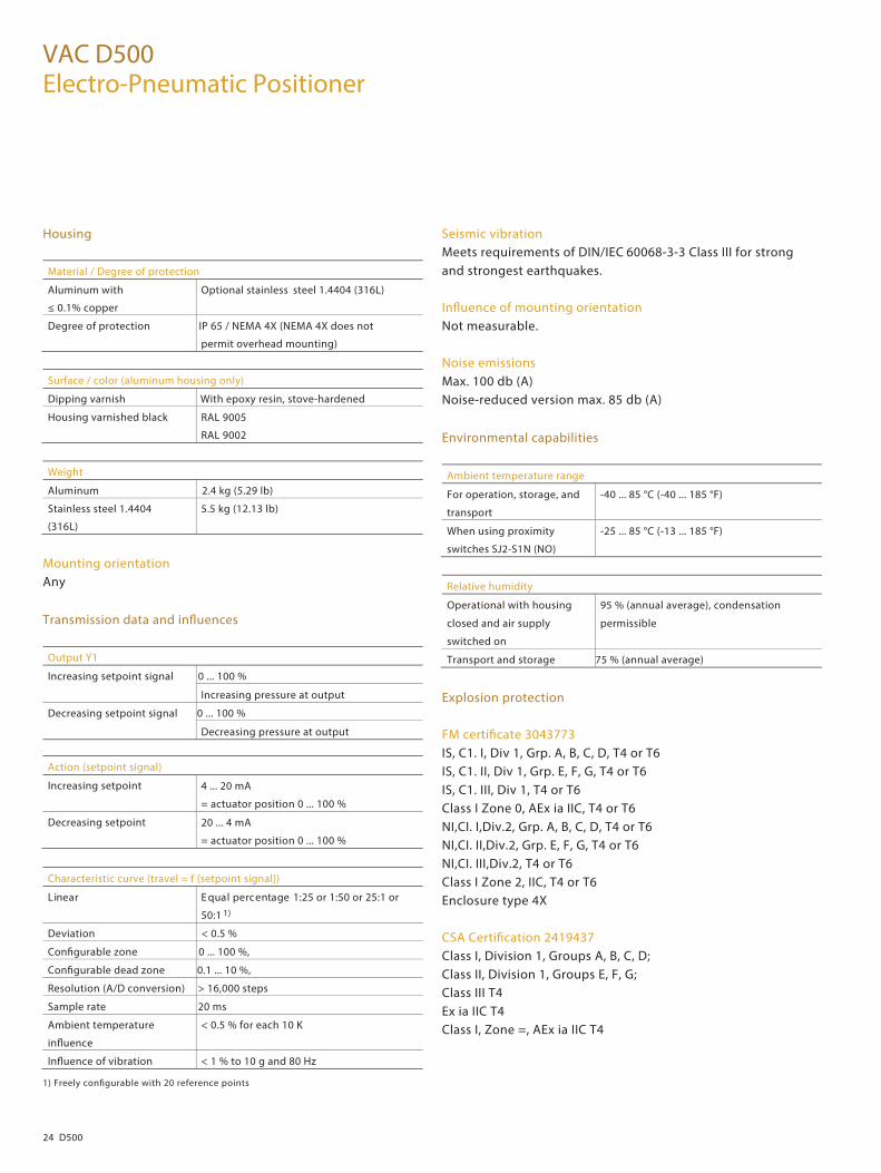
Housing
Material / Degree of protection
Aluminum with
≤ 0.1% copper
Optional stainless steel 1.4404 (316L)
Degree of protection IP 65 / NEMA 4X (NEMA 4X does not
permit overhead mounting)
Surface / color (aluminum housing only)
Dipping varnish With epoxy resin, stove-hardened
Housing varnished black RAL 9005
RAL 9002
Weight
Aluminum 2.4 kg (5.29 lb)
Stainless steel 1.4404
(316L)
5.5 kg (12.13 lb)
Mounting orientation Any
Transmission data and in�uences
Output Y1
Increasing setpoint signal 0 ... 100 %
Increasing pressure at output
Decreasing setpoint signal 0 ... 100 %
Decreasing pressure at output
Action (setpoint signal)
Increasing setpoint 4 ... 20 mA
= actuator position 0 ... 100 %
Decreasing setpoint 20 ... 4 mA
= actuator position 0 ... 100 %
Characteristic curve (travel = f {setpoint signal})
egatnecrep lauqE raeniL 1:25 or 1:50 or 25:1 or
50:1 1)
Deviation < 0.5 %
Con�gurable zone 0 ... 100 %,
Con�gurable dead zone 0.1 ... 10 %,
Resolution (A/D conversion) > 16,000 steps
Sample rate 20 ms
Ambient temperature
in�uence
< 0.5 % for each 10 K
In�uence of vibration < 1 % to 10 g and 80 Hz
1) Freely con�gurable with 20 reference points
Seismic vibration Meets requirements of DIN/IEC 60068-3-3 Class III for strong and strongest earthquakes. In�uence of mounting orientation Not measurable. Noise emissions Max. 100 db (A) Noise-reduced version max. 85 db (A)
Environmental capabilities
Ambient temperature range
For operation, storage, and
transport
-40 ... 85 °C (-40 ... 185 °F)
When using proximity
switches SJ2-S1N (NO)
-25 ... 85 °C (-13 ... 185 °F)
Relative humidity
Operational with housing
closed and air supply
switched on
95 % (annual average), condensation
permissible
Transport and storage 75 % (annual average)
Explosion protection FM certi�cate 3043773 IS, C1. I, Div 1, Grp. A, B, C, D, T4 or T6 IS, C1. II, Div 1, Grp. E, F, G, T4 or T6 IS, C1. III, Div 1, T4 or T6 Class I Zone 0, AEx ia IIC, T4 or T6 NI,CI. I,Div.2, Grp. A, B, C, D, T4 or T6 NI,CI. II,Div.2, Grp. E, F, G, T4 or T6 NI,CI. III,Div.2, T4 or T6 Class I Zone 2, IIC, T4 or T6 Enclosure type 4X CSA Certi�cation 2419437 Class I, Division 1, Groups A, B, C, D; Class II, Division 1, Groups E, F, G; Class III T4 Ex ia IIC T4 Class I, Zone =, AEx ia IIC T4
Change from two to one column

D500 25
Change from one to two columns
Optional upgrades
Module for analog position feedback 1)
Signal range 4 ... 20 mA (con�gurable split ranges)
Supply, 2-wire circuitry 24 V DC (10 ... 30 V DC)
Characteristic curve
(con�gurable)
Increasing or decreasing
Deviation < 1 %
Without a signal from the positioner (e. g., "no power" or "initializing") the module sets the output to > 20 mA (alarm level) Module for binary position feedback 1) Two switches for digital position feedback (position adjustable within the range of 0 ... 100 %, ranges cannot overlap) Current circuits acc. to DIN 19234 / NAMUR
Supply voltage 5 ... 30 V DC
Signal current < 1.2 mA: Switching state logical "0"
"1" lacigol etats gnihctiwS :Am 1.2 >
Direction of action normally logical "0" or logical "1"
(con�gurable)
Module for universal input 1) Module for a 4 … 20 mA input for universal use. The range can be scaled. It is used for advanced valve diagnostics. For example, an ultrasonic sensor can be connected to detect a faulty valve seat or a phonometer can be connected to detect cavitation. The limit values for detecting overshoot can be freely selected.
Universal input
Nominal range 4 ... 20 mA
Load voltage at 20 mA 8 V
Impedance at 20 mA 400 Ω
Module for the emergency shutdown function 1)
Supply voltage 24 V DC (20 ... 30 V DC) (electrically
isolated from input signal)
Safe position active At voltage < 5 V
Explosion protection: see certi� cate (operating instructions)
1) There are two slots for the option modules. Any combination of di�erent option modules is possible. However, identical option modules cannot be combined.
A separate 24 V DC signal is applied to the emergency shutdown module; it connects the signal from the microprocessor through to the I/P module. When the 24 V DC signal is interrupted, the pneumatic module executes the respective safety function, depending on the mechanical construction: The positioner output 1 is depressurized, and the valve is moved to the safe position. In case of a "double-acting" actuator the second output 2 is additionally pressurized. The emergency shutdown module works independently of the mother board, i.e., all information from the actuator is available in the control system at any time.

VAC D500 Electro-Pneumatic Positioner
26 D500
Binary position feedback with proximity switches Two proximity switches for independent position signaling. Switching points adjustable between 0 … 100 % Current circuits acc. to DIN 19234 / NAMUR
Supply voltage 5 ... 11 V DC
Signal current < 1.2 mA: Switching state logical "0"
"1" lacigol etats gnihctiwS :Am 1.2 >
Direction of action (logical state)
Position
Proximity switch < Lim. 1 > Lim. 1 < Lim. 2 > Lim. 2
SJ2-SN (NC) 0 1 1 0
SJ2-S1N (NO) 1 0 0 1
When using proximity switch SJ2_S1N (NO), the positioner may only be used at an ambient temperature range of -25 ... 85 °C (-13 ... 185 °F). Binary position feedback with 24 V microswitches Two microswitches for independent position signaling. Switching points adjustable between 0 … 100 %.
Voltage max. 24 V AC / DC
Load rating max. 2 A
Contact surface 10 µm Gold (AU)
Mechanical position indicator Indicator disk in enclosure cover, linked with positioner feedback shaft. Contactless position sensor (option) In ambient conditions (constant valve movements, for example, which are transmitted to the sensor axis by the process pressure), the positioner can be tted with a contactless position sensor. Pressure option The pressure option comprises 3 absolute pressure sensors which facilitate pressure-based valve diagnostics (valve signature, for example). The supply air pressure and the output pressures can also be monitored. The zero points of the pressure sensors can be calibrated both locally on th e device and using the DTM. These options are also available for retr tting by Service.
Change from two to one column
D500 27
Change from one to two columns
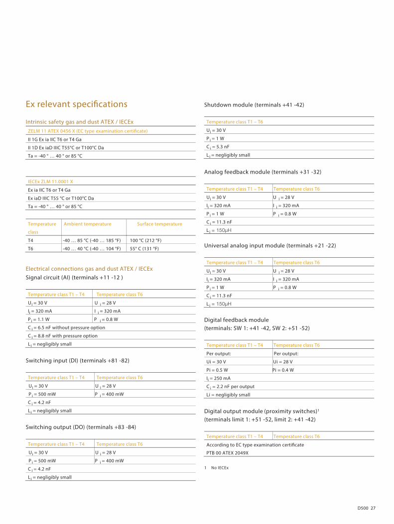
Ex relevant speci�cations
Intrinsic safety gas and dust ATEX / IECEx
ZELM 11 ATEX 0456 X (EC type examination certi�cate)
II 1G Ex ia IIC T6 or T4 Ga
II 1D Ex iaD IIIC T55°C or T100°C Da
Ta = -40 ° … 40 ° or 85 °C
IECEx ZLM 11.0001 X
Ex ia IIC T6 or T4 Ga
Ex iaD IIIC T55 °C or T100°C Da
Ta = -40 ° … 40 ° or 85 °C
Temperature
class
Ambient temperature Surface temperature
T4 -40 … 85 °C (-40 … 185 °F) 100 °C (212 °F)
T6 -40 … 40 °C (-40 … 104 °F) 55° C (131 °F)
Electrical connections gas and dust ATEX / IECEx
Signal circuit (AI) (terminals +11 -12 )
Temperature class T1 – T4 Temperature class T6
Ui = 30 V U i = 28 V
Ii = 320 mA I i = 320 mA
P i = 1.1 W P i = 0.8 W
C i = 6.5 nF without pressure option
C i = 8.8 nF with pressure option
Li = negligibly small
Switching input (DI) (terminals +81 -82)
Temperature class T1 – T4 Temperature class T6
Ui = 30 V U i = 28 V
P i = 500 mW P i = 400 mW
C i = 4.2 nF
Li = negligibly small
Switching output (DO) (terminals +83 -84)
Temperature class T1 – T4 Temperature class T6
Ui = 30 V U i = 28 V
P i = 500 mW P i = 400 mW
C i = 4.2 nF
Li = negligibly small
Shutdown module (terminals +41 -42)
Temperature class T1 – T6
Ui = 30 V
P i = 1 W
C i = 5.3 nF
Li = negligibly small
Analog feedback module (terminals +31 -32)
Temperature class T1 – T4 Temperature class T6
Ui = 30 V U i = 28 V
Ii = 320 mA I i = 320 mA
P i = 1 W P i = 0.8 W
C i = 11.3 nF
Li
Universal analog input module (terminals +21 -22)
Temperature class T1 – T4 Temperature class T6
Ui = 30 V U i = 28 V
Ii = 320 mA I i = 320 mA
P i = 1 W P i = 0.8 W
C i = 11.3 nF
Li
Digital feedback module (terminals: SW 1: +41 -42, SW 2: +51 -52)
Temperature class T1 – T4 Temperature class T6
Per output: Per output:
Ui = 30 V Ui = 28 V
Pi = 0.5 W Pi = 0.4 W
Ii = 250 mA C i = 2.2 nF per output
Li = negligibly small
Digital output module (proximity switches)1 (terminals limit 1: +51 -52, limit 2: +41 -42)
Temperature class T1 – T4 Temperature class T6
According to EC type examination certi�cate
PTB 00 ATEX 2049X
1 No IECEx
VAC D500 Electro-Pneumatic Positioner
28 D500
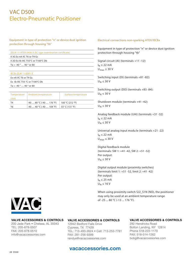
Equipment in type of protection "n" or device dust ignition protection through housing "tb"
ZELM 11 ATEX 0456 X (EC type
II 3G Ex nA IIC T6 or T4 Gc
II 2D Ex tb IIIC T55°C or T100°C Db
Ta = -40 ° … 40 ° or 80
IECEx ZLM 11.0001 X
Ex nA IIC T6 or T4 Gc
Ex tb IIIC T55 °C or T100°C Db
Ta = -40 ° … 40 ° or 80
Temperature
class
Ambient temperature Surface temperature
T4 -40 … 80 °C (-40 … 176 °F) 100 °C (212 °F)
T6 -40 … 40 °C (-40 … 104 °F) 55° C (131 °F)
Electrical connections non-sparking ATEX/IECEx
Equipment in type of protection "n" or device dust ignition protection through housing "tb" Signal circuit (AI) (terminals +11 -12): IN ≤ 22 mA Umax ≤ 30 V Switching input (DI) (terminals +81 -82): UN ≤ 30 V Switching output (DO) (terminals +83 -84): UN ≤ 30 V Shutdown module (terminals +41 -42): UN ≤ 30 V
Analog feedback module (UAI) (terminals +31 -32) IN ≤ 22 mA UN ≤ 30 V Universal analog input modu le (terminals +21 -22) IN ≤ 22 mA Umax ≤ 30 V Digital feedback module (terminals: SW 1: +41 -42, SW 2: +51 -52) Per output: UN ≤ 30 V Digital output module (proximity switches) (terminals limit 1: +51 -52, limit 2: +41 -42) Per output: IN ≤ 25 mA UN ≤ 16 V When using proximity switch SJ2_S1N (NO), the positioner may only be used at an ambient temperature range of -25 ... 80 °C (-13 ... 176 °F).
Change from two to one column
vacaccessories.com
VALVE ACCESSORIES & CONTROLS12942 Bedford Falls Drive Cypress, TX 77429TEL: 713-493-2624 • Cell: 713-253-7781FAX: [email protected]
VALVE ACCESSORIES & CONTROLS200 Jade Park • Chelsea, AL 35043TEL: 205-678-0507 FAX: [email protected]
VALVE ACCESSORIES & CONTROLS292 Hendricks RoadBolton Landing, NY 12814Phone 518-222-1170FAX: [email protected]