vacuum equipment vacuum ejector variationsca01.smcworld.com/catalog/best-guide-en/pdf/6-4-p... ·...
TRANSCRIPT
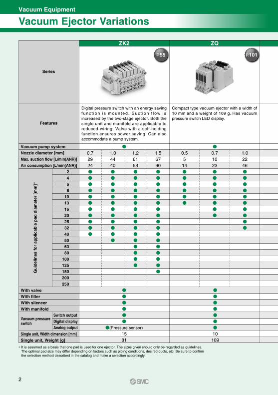
Vacuum Equipment
P.55
Series
Features
Gu
idel
ines
fo
r ap
plic
able
pad
dia
met
er [
mm
]∗
Vacuum pump systemNozzle diameter [mm]Max. suction flow [L/min(ANR)]Air consumption [L/min(ANR)]
Vacuum pressure switch
2468
10131620253240506380
100125150200250
1.26158
1.04440
1.56790
0.72924
Switch outputDigital displayAnalog output
Digital pressure switch with an energy saving func t ion i s moun ted . Suc t ion f l ow i s increased by the two-stage ejector. Both the single unit and manifold are applicable to reduced-wiring. Valve with a self-holding function ensures power saving. Can also accommodate a pump system.
Compact type vacuum ejector with a width of 10 mm and a weight of 109 g. Has vacuum pressure switch LED display.
ZK2
(Pressure sensor)
1581
P.101
0.71023
1.02246
0.5514
ZQ
10109
With valveWith filterWith silencerWith manifold
Single unit, Width dimension [mm]Single unit, Weight [g]
∗ It is assumed as a basis that one pad is used for one ejector. The sizes given should only be regarded as guidelines.The optimal pad size may differ depending on factors such as piping conditions, desired ducts, etc. Be sure to confirmthe selection method described in the catalog and make a selection accordingly.
Vacuum Ejector Variations
2

Best Pneumatics 4P.131 P.181 P.207
Necessary functions can be combined through modular design.Double solenoids provide a self-holding function.Can also accommodate a vacuum pump.
ZR ZB ZL
Quick response, Energy saving, Compact/LightweightWith vacuum pressure switch, Can copy to up to 10 switches simultaneously.
Suction flow rate increased by a 3-stage diffuser construction.Functions such as a digital vacuum switch or a vacuum pressure gauge can be selected.
Vacuum Ejector Variations
1.02553
0.32
3.5
0.43.56.5
0.54.510
0.6718
1.34286
1.563102
1.874155
2.095194
31275
1046
1.210063
36600
1.2 x 2200126
40800
3 A

0.5613
0.71227
1.02652
1.34084
1.558113
1.876162
2.090196
0.71229
0.5714
12.87
14 to 225 to 23.3
Vacuum Equipment
Vacuum Ejector Variations
P.221
Can be connected with the combination of a one-touch and a screw-in connection.
Vacuum port and supply port are located collinearly to facilitate piping.
ZH
P.261
ZU
Series
Features
Gu
idel
ines
fo
r ap
plic
able
pad
dia
met
er [
mm
]∗
Vacuum pump systemNozzle diameter [mm]Max. suction flow [L/min(ANR)]Air consumption [L/min(ANR)]
Vacuum pressure switch
2468
10131620253240506380
100125150200250
Switch outputDigital displayAnalog output
With valveWith filterWith silencerWith manifold
Single unit, Width dimension [mm]Single unit, Weight [g]
4

Best Pneumatics 4P.276 P.279 P.281
1/8
—
50
30 30 5
1/4
—
200
Series
Features
Unrestricted 360° piping tube mountingWith One-touch fitting
Pleated element provides a large filter area.Adaptable for a manifold application
IN/OUT straight pipingWith One-touch fitting
ZFB ZFCZFA
Air flow [L/min(ANR)]
Filtration [µm]
Screw-in
Applicable tubing O.D.for One-touch fittings (Metric)
Portsize
—
6
30
—
8
50
—
10
75
—
4
10
—
4
10
—
6
2030
—
8
70
—
10
80
—
12
100
Vacuum Equipment
Suction Filter
ZFC050P.272
Vacuum Filter
AFJ SeriesP.779
Air Suction Filter Variations
5

Pad Diameter List : ZP3 series : ZP3E series : ZP2 series : ZP series
Pad type SymbolPad diameter
SymbolPage
ofZP3
Pageof
ZP3E
Pageof
ZP2
PageofZP0.8 1.1 1.5 2 3 3.5 4 5 6 7 8 9 10 11 13 14 15 16 18 20 25 30 32 40 46 50 63 80 100 125 150 250 300 340
Flat
U — —— Note)
— — — — — — — — — — — — — — — — — U P.324 — P.528 P.637
MU — — — Note) — Note) Note) Note) Note) — Note) — Note) — — — Note) — — — — — — — — — — — — — — — — — MU — — P.529 —
EU — — — Note) — — Note) — Note) — — — — — — — — — — — — — — — — — — — — — — — EU — — P.532 —
AU — — — — — Note) — — — — — — — — — — — — — — — — — — — — — — — — AU — — P.535 —
Flat with rib C — — — — — — — — — — — — — — — — — — — — — — — C — — P.528 P.637
Flat with groove UM — — — — — — — — — — — — — — — — — — — — — UM P.324 P.404 — —
Bellows typewith groove BM — — — — — — — — — — — — — — — — — — — — — — — — — — — BM — P.404 — —
Thin flat(pad) UT — — — — — — — — — — — — — — — — — — — — — — — — — UT — —
P.528P.537
P.637Thin flatwith rib CT — — — — — — — — — — — — — — — — — — — — — — — — — — — — — — — CT — — —
Bellows (pad)
B — — — — — ——
—Note)
—Note)
— — — — — — — — — — — — — — — B P.324 — P.528
J — — — — — — — — — — Note) — — Note) — — Note) Note) — — — — — — — — — — — — J — — P.540 —
MB — — — — — — Note) — Note) — Note) — Note) — — — Note) — — — — — — — — — — — — — — — — MB — — P.541 —
ZJ — — — — — — — — — — — — — — — — — — — — — — — — — — — — ZJ — — P.543 —
Deep D — — — — — — — — — — — — — — — — — — — — — — — — — — — — — — D — — — P.637
Nozzle pad AN — — — — — — — — — — — — — — — — — — — — — — — — — — — — — — — — AN — — P.536 —
Flat pad MT — — — — — — — — — — — — Note) — — — Note) — — Note) Note) Note) — — — — — — — — — — — — MT — — P.538 —
Oval padW
— — ——
—
3.5 x 74 x 104 x 204 x 30
5 x 105 x 205 x 30
6 x 106 x 206 x 30
—
8 x 208 x 30
— — — — — — — — — — — — — — — — — — — — — — —W — — P.550 —
U 2 x 4 3.5 x 7 4 x 10— — — U — — — P.637
Heavy-duty pad
H — — — — — — — — — — — — — — — — — — — — — — — — — H — — P.566 P.582
HT — — — — — — — — — — — — — — — — — — — — — — — — — — — — — — — — HT — — P.566 —
HB — — — — — — — — — — — — — — — — — — — — — — — — — — HB — — P.568 P.582
HW — — — — — — — — — — — — — — — — — — — — —30 x 50
— — — — — — — — — — — — HW — — P.569
—
Mark-free padU — — — — — — — — — — — — — — — — — — — — — — — — — U — — P.560
H — — — — — — — — — — — — — — — — — — — — — — — — — — — — H — — P.561
Sponge pad S — — — — — — — — — — — — — — — — — — — — — — — — — — — — — S — — P.563
Resinattachment K — — — — — — — — — — — — — — — — — — — — — — — — — — K — — P.562
Pad with ballspline buffer U — — — — — — — — — — — — — — — — — — — — — — — — — — — — — — U — — P.557
Heavy-dutyball joint pad
H — — — — — — — — — — — — — — — — — — — — — — — — — — — — H — — P.570
HB — — — — — — — — — — — — — — — — — — — — — — — — — — — — HB — — P.576
Related pad
Bellows
Flat
Oval
Non-contact gripper Note) The ZP2 series is blast type.
The ZP3 series is available from ø1.5 to ø16. If you need other sizes or shapes, choose from the ZP or ZP2 series.
Made to Order
Vacuum Equipment
Vacuum Pad Variations ZP3/ZP3E/ZP2/ZP Series
6

Pad type SymbolPad diameter
SymbolPage
ofZP3
Pageof
ZP3E
Pageof
ZP2
PageofZP0.8 1.1 1.5 2 3 3.5 4 5 6 7 8 9 10 11 13 14 15 16 18 20 25 30 32 40 46 50 63 80 100 125 150 250 300 340
Flat
U — —— Note)
— — — — — — — — — — — — — — — — — U P.324 — P.528 P.637
MU — — — Note) — Note) Note) Note) Note) — Note) — Note) — — — Note) — — — — — — — — — — — — — — — — — MU — — P.529 —
EU — — — Note) — — Note) — Note) — — — — — — — — — — — — — — — — — — — — — — — EU — — P.532 —
AU — — — — — Note) — — — — — — — — — — — — — — — — — — — — — — — — AU — — P.535 —
Flat with rib C — — — — — — — — — — — — — — — — — — — — — — — C — — P.528 P.637
Flat with groove UM — — — — — — — — — — — — — — — — — — — — — UM P.324 P.404 — —
Bellows typewith groove BM — — — — — — — — — — — — — — — — — — — — — — — — — — — BM — P.404 — —
Thin flat(pad) UT — — — — — — — — — — — — — — — — — — — — — — — — — UT — —
P.528P.537
P.637Thin flatwith rib CT — — — — — — — — — — — — — — — — — — — — — — — — — — — — — — — CT — — —
Bellows (pad)
B — — — — — ——
—Note)
—Note)
— — — — — — — — — — — — — — — B P.324 — P.528
J — — — — — — — — — — Note) — — Note) — — Note) Note) — — — — — — — — — — — — J — — P.540 —
MB — — — — — — Note) — Note) — Note) — Note) — — — Note) — — — — — — — — — — — — — — — — MB — — P.541 —
ZJ — — — — — — — — — — — — — — — — — — — — — — — — — — — — ZJ — — P.543 —
Deep D — — — — — — — — — — — — — — — — — — — — — — — — — — — — — — D — — — P.637
Nozzle pad AN — — — — — — — — — — — — — — — — — — — — — — — — — — — — — — — — AN — — P.536 —
Flat pad MT — — — — — — — — — — — — Note) — — — Note) — — Note) Note) Note) — — — — — — — — — — — — MT — — P.538 —
Oval padW
— — ——
—
3.5 x 74 x 104 x 204 x 30
5 x 105 x 205 x 30
6 x 106 x 206 x 30
—
8 x 208 x 30
— — — — — — — — — — — — — — — — — — — — — — —W — — P.550 —
U 2 x 4 3.5 x 7 4 x 10— — — U — — — P.637
Heavy-duty pad
H — — — — — — — — — — — — — — — — — — — — — — — — — H — — P.566 P.582
HT — — — — — — — — — — — — — — — — — — — — — — — — — — — — — — — — HT — — P.566 —
HB — — — — — — — — — — — — — — — — — — — — — — — — — — HB — — P.568 P.582
HW — — — — — — — — — — — — — — — — — — — — —30 x 50
— — — — — — — — — — — — HW — — P.569
—
Mark-free padU — — — — — — — — — — — — — — — — — — — — — — — — — U — — P.560
H — — — — — — — — — — — — — — — — — — — — — — — — — — — — H — — P.561
Sponge pad S — — — — — — — — — — — — — — — — — — — — — — — — — — — — — S — — P.563
Resinattachment K — — — — — — — — — — — — — — — — — — — — — — — — — — K — — P.562
Pad with ballspline buffer U — — — — — — — — — — — — — — — — — — — — — — — — — — — — — — U — — P.557
Heavy-dutyball joint pad
H — — — — — — — — — — — — — — — — — — — — — — — — — — — — H — — P.570
HB — — — — — — — — — — — — — — — — — — — — — — — — — — — — HB — — P.576
Products other than above Vacuum pad fortransferring disks…P.592
Vacuum savingvalve…P.627
Vacuum pad for fixing panel…P.593
Best Pneumatics 4Vacuum Pad Variations
7

Vacuum Equipment
Vacuum Pad ZP3 Series
19.5mm
12mm
3 mm
ZP (Current model) ZP (Current model)
8.5 mm
ZP3ZP3 ZP3ZP3
ø4ø2
Pad diameterType
Actual size Actual size
Variations
Space-saving ø2 piping reduces working space!
Pad diameter ø1.5 added!
ø1.5 ø2 ø3.5 ø4 ø6 ø8 ø10 ø13 ø16
Pad unit
Overall length is shortened.
With adapter9 mm shortened
In the case of Flat type (Pad diameter: ø2)
Max. 11 mm shortenedMax.
Area
75%reduced
Area
28.26 mm2
ø2 x 7 pcs.Area
113.04 mm2
ø4 x 7 pcs.
• Male thread• Female thread• Barb fitting (Applicable tubing: ø2)• One-touch fitting
(Applicable tubing: ø2)
• Female thread• Barb fitting (Applicable tubing: ø2)• One-touch fitting (Applicable tubing: ø2)
Vertical Lateral
Barb fitting Barb fittingOne-touch fitting One-touch fitting
Flat
Flatwith groove
Bellows
8
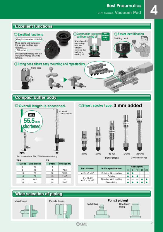
Best Pneumatics 4ZP3 Series Vacuum Pad
Wide selection of piping
For ø2 piping!Male thread Female thread
Short stroke type: 3 mm added
ø1.5, ø2, ø3.5
ø4, ø6, ø8ø10, ø13, ø16
ZP3Stroke
3
6
10
15
20
25
Overall length (mm)
40
46
56
59
66.5
—
ZPStroke
3
6
10
15
20
25
Overall length (mm)—
78.5
109.5
114.5
—124.5
Pad diameter
Pad diameter ø8, Flat, With One-touch fitting
Overall length is shortened.
Excellent functions
Fixing boss allows easy mounting and repeatability.
Easier identificationSMC logo mark
Compact buffer body
Fixing boss
ZP3 ZP
One-touch fitting
Barb fitting
Buffer stroke
3 mm
New shape for connecting with the adapter prevents the pad from coming off.
Adsorption surface is shot-blasted
Micro-dents and bumps on the surface facilitate easy removal.
Less contact surface with the workpiece makes it easy to remove.
55.5 mm
shortened
Buffer specifications
Rotating, Non-rotating
Rotating
Rotating, With bushing
Non-rotating
3
—
6
—
10
—
—
15
—
—
20
—
—
6 mm 10 mm 15∗ mm 20∗ mm
Excellent functions
∗ Lateral vacuum inlet
Construction to prevent pad from coming off
Pad diameter
from ø1.5
With groove
Max.
Stroke (mm)
(∗ With bushing)
9

Vacuum Equipment
Vacuum Pad ZP3 Series Variations
Pad diameterMaterialType Page
ø1.5 ø2 ø3.5 ø4 ø6 ø8 ø10 ø13 ø16
Bellows
Flat with groove
NBR
Silicone rubber
Urethane rubber
FKM
Conductive NBR
Conductive silicone rubber
For adsorption ofgeneral workpiecesFor adsorption of workpieces with flat and notdeformed surface
For a workpiece which is likely to deform For releasing a workpiece certainly
For adsorption of work pieces with inclined surface
Flat
P.297
10

Best Pneumatics 4ZP3 Series Variations Vacuum Pad
Page
Without buffer(with adapter)
Without buffer(with adapter)
Stroke with buffer 3 mm 6 mm10 mm15 mm20 mm
Stroke with buffer 3 mm 6 mm10 mm15 mm20 mm
Vacuum inlet direction Buffer attachment Vacuum inlet
Male thread
Female thread
Barb fitting
One-touch fitting
M3, M5
M3, M5
ø2, ø4, ø6
Soft nylon/Polyurethane tubing ø4, ø6
Polyurethane tubing ø2
Soft nylon/Polyurethane tubing ø4, ø6
Polyurethane tubing ø2
Soft nylon/Polyurethane tubing ø4, ø6
Polyurethane tubing ø2
Soft nylon/Polyurethane tubing ø4, ø6
Polyurethane tubing ø2
Female thread
Barb fitting
One-touch fitting
M3, M5
ø2, ø4, ø6
Female thread
Barb fitting
One-touch fitting
M3, M5
ø2, ø4, ø6
Female thread
Barb fitting
One-touch fitting
M3, M5
ø2, ø4, ø6
ZP3-T -
ZP3-T - -J
JBK
ZP3-Y - -J
JBK
ZP3-Y --
P.326
P.338
P.348
P.354
Vertical
Lateral
Lateral
Vertical
11
With groove
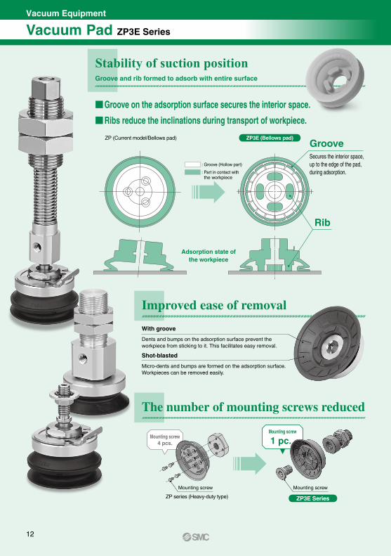
Dents and bumps on the adsorption surface prevent theworkpiece from sticking to it. This facilitates easy removal.
Improved ease of removal
Groove and rib formed to adsorb with entire surface
Stability of suction position
Shot-blasted
Micro-dents and bumps are formed on the adsorption surface.Workpieces can be removed easily.
Mounting screw4 pcs.
Mounting screw
1 pc.
ZP series (Heavy-duty type)
The number of mounting screws reduced
Mounting screw
ZP3E Series
Mounting screw
Groove on the adsorption surface secures the interior space. Ribs reduce the inclinations during transport of workpiece.
ZP (Current model/Bellows pad) ZP3E (Bellows pad)
: Groove (Hollow part)
: Part in contact with the workpiece
GrooveSecures the interior space, up to the edge of the pad, during adsorption.
Adsorption state ofthe workpiece
Rib
Vacuum Equipment
Vacuum Pad ZP3E Series
12

ZP2/Flat type ZP3E/Flat type with groovePad diameter Weight [g] Weight [g]
ø32 — 56ø40 91 57ø50 110 75ø63 230 150ø80 270 160ø100 430 190ø125 560 270
Direct mounting with male thread added
ZP series (Heavy-duty type)
Metal plate
Rubber pad
Holder
Plate
Stopper
Pad
The rubber pad and metalpart can be separated.
Can be disposed of separately.
For use where adsorption marks must not be left on workpieces.
Mark-free
Mark-freeNBR pad
The metal parts and rubber parts
can be separated completely.
ZP3E Series
ZP (Current model) ZP3EPad diameter Suction port Area [mm2] Suction port Area [mm2]
ø32 — —ø8.4 55.4ø40
ø6 28.3ø50ø63
ø8 50.2ø16.4 211
ø80ø100
ø10 78.52ø125
ø8 ø16.4
Applicable to workpieces with a large suction flow rate and high permeability, and vacuum blow pumps with large suction flow rates.
Directmounting
Reduced in height Easy mounting with tightening with a hexagonal wrench
Weight reduced by changing the internal structure and materials
Suction flow rate increased
The pad material when weight was measured is NBR.
Ball joint type pad weight reducedWeight reduced
by up to
290 g
No trace ofthe pad!
Doublesuction port size
Pad diameter: ø63, ø80Compared with the ZP series( )
Seal washer
Clear traceof the pad
Standard pad
Standard type Ball joint type
ZP3E
Best Pneumatics 4ZP3E Series Vacuum Pad
13

FormPad diameter
Material Pageø32 ø40 ø50 ø63 ø80 ø100 ø125
ZP3E- UM-
Flat type with grooveFor adsorption of general workpieces. To be used when adsorption surface of the workpiece is flat and not deformed.
NBRSilicone rubber
Urethane rubberFKM
Mark-free NBR
P.404
ZP3E- BM-
Bellows type with grooveTo be used when adsorption surface of the workpiece is slanted.
P.404
Pad Unit Variations
Vacuum Equipment
Vacuum Pad ZP3E Series Variations
14
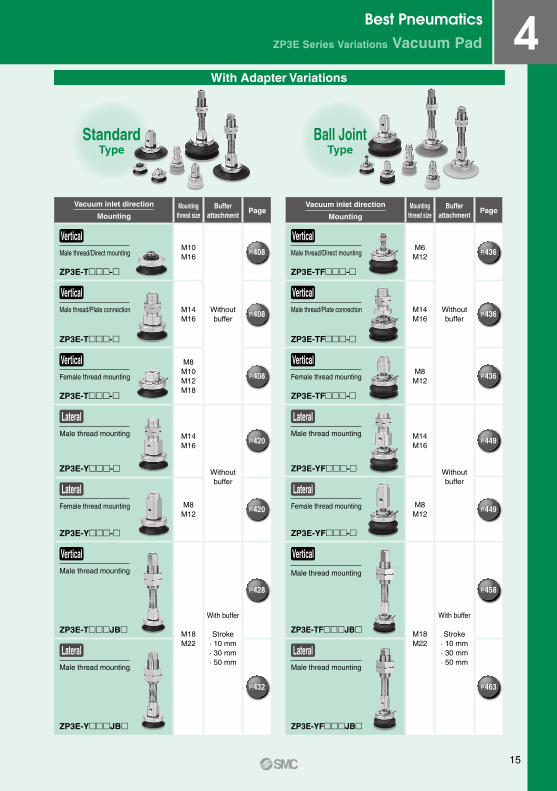
Vacuum inlet direction
MountingMounting
thread sizeBuffer
attachmentPage
VerticalMale thread/Direct mounting
M6M12
Withoutbuffer
P.436
ZP3E-TF -
VerticalMale thread/Plate connection M14
M16P.436
ZP3E-TF -
VerticalFemale thread mounting
M8M12
P.436
ZP3E-TF -
LateralMale thread mounting M14
M16
Withoutbuffer
P.449
ZP3E-YF -
LateralFemale thread mounting M8
M12P.449
ZP3E-YF -
VerticalMale thread mounting
M18M22
With buffer
Stroke· 10 mm· 30 mm· 50 mm
P.458
ZP3E-TF JB
LateralMale thread mounting
P.463
ZP3E-YF JB
Vacuum inlet direction
MountingMounting
thread sizeBuffer
attachmentPage
VerticalMale thread/Direct mounting
M10M16
Withoutbuffer
P.408
ZP3E-T -
VerticalMale thread/Plate connection M14
M16P.408
ZP3E-T -
VerticalFemale thread mounting
M8M10 M12M18
P.408
ZP3E-T -
LateralMale thread mounting M14
M16
Withoutbuffer
P.420
ZP3E-Y -
LateralFemale thread mounting M8
M12P.420
ZP3E-Y -
VerticalMale thread mounting
M18M22
With buffer
Stroke· 10 mm· 30 mm· 50 mm
P.428
ZP3E-T JB
LateralMale thread mounting
P.432
ZP3E-Y JB
StandardType
Ball JointType
With Adapter Variations
Best Pneumatics 4ZP3E Series Variations Vacuum Pad
15
ø6, ø7, ø8
ø5, ø6
ø6, ø8
ø3, ø4
ø0.8, ø1.1
ø2, ø3.5, ø4ø5, ø6, ø8ø10, ø15
ø2, ø4, ø6ø8, ø15
ø2, ø3, ø4ø6, ø8
U
C
UT
B
MU
EU
AU
AN
UT
MT
J
MB
ZJ
Flat
Flat with rib
Thin flat
Bellows
Flat
Nozzle
Thin flat(Skirt)
Bellows(Multistage type)
Bellows
Thin flat(With groove)
ø5, ø6, ø11ø14, ø18 ø20
ø6, ø9, ø10ø14, ø15ø16, ø25ø30
ø4, ø6, ø8ø10, ø15ø20
ø15, ø20ø30, ø40ø46
ø2, ø4, ø5ø6, ø40, ø46
ø10, ø15ø20, ø25ø30
ZP SeriesCommon adapter
ZP SeriesCommon adapter
—
ZP Series Common adapter
—
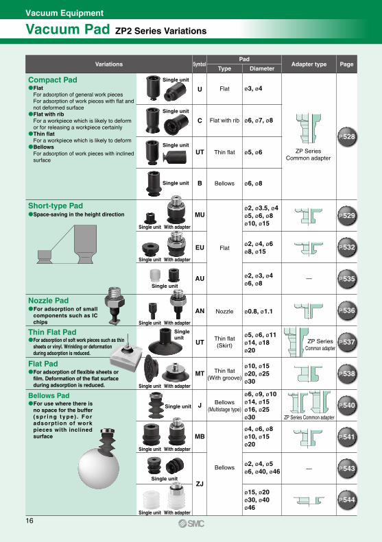
TypeSymbolVariations
Pad
DiameterAdapter type Page
Compact PadFlat
For adsorption of general work piecesFor adsorption of work pieces with flat and not deformed surfaceFlat with rib
For a workpiece which is likely to deform or for releasing a workpiece certainlyThin flat
For a workpiece which is likely to deformBellows
For adsorption of work pieces with inclined surface
Short-type PadSpace-saving in the height direction
Nozzle PadFor adsorption of small
components such as IC chips
Thin Flat PadFor adsorption of soft work pieces such as thin
sheets or vinyl. Wrinkling or deformation during adsorption is reduced.
Bellows PadFor use where there is
no space for the buffer ( s p r i n g t y p e ) . F o r adsorption of work pieces with inclined surface
Flat PadFor adsorption of flexible sheets or
film. Deformation of the flat surface during adsorption is reduced.
With adapterSingle unit
With adapterSingle unit
With adapterSingle unit
Single unit
Single unit
Single unit
Single unit
Single unit
With adapterSingle unit
With adapterSingle unit
Single unit
Single unit
With adapterSingle unit
P.544
Vacuum Equipment
Vacuum Pad ZP2 Series Variations
Single unit
P.528
P.529
P.532
P.535
P.536
P.537
P.538
P.540
P.541
P.543
16

Best Pneumatics 4Type
U
VariationsPad
DiameterAdapter type Page
ø4
ø6, ø8
ø6, ø8
ø10, ø15ø25, ø30
ø2, ø3.5, ø4ø5, ø6, ø8ø10, ø15
ø2, ø4, ø6
ø10, ø15ø20, ø25ø30
ø4, ø6, ø8ø10, ø15ø20
ø2, ø4ø6, ø8
Blast-type PadBlast treatment to create finely
uneven surface for adsorption. Work pieces can be removed easily.
Oval PadFor work pieces with limitations
on the adsorption surface
Pad with Ball Spline BufferBall spline guide is
used to the buffer.
Flat
Flat with rib
Bellows
Bellows(Multistage type)
Flat
Flat
Thin flat(With groove)
Bellows
Flat
C
B
J
MU
EU
MT
MB
U
W
ZP SeriesCommon adapter
Oval
3.5 x 7
4 x 105 x 106 x 10
4 x 205 x 206 x 208 x 20
4 x 305 x 306 x 308 x 30
ZP SeriesCommon adapter
Single unit
With adapterSingle unit
With adapterSingle unit
Single unit
With adapterSingle unit
Single unit
Single unit
With adapterSingle unit
Single unit
With adapter: Vacuum inlet direction
With buffer: Vacuum inlet direction
With buffer: Vacuum inlet direction
With buffer: Vacuum inlet direction
P.528
P.540
P.529
P.532
P.538
P.541
P.550
P.551
P.552
P.554
P.556
P.557
Symbol
Vertical
Vertical
With adapter: Vacuum inlet direction
Lateral
Lateral
Vertical
ZP2 Series Variations Vacuum Pad
17

Type
U
VariationsPad
DiameterAdapter type Page
ø4, ø6, ø8ø10, ø16ø25, ø32ø40, ø50
Mark-free PadFor use where adsorption marks must
not be left on work pieces.
Resin AttachmentMark-free.
Prevents sticking of the rubber and the workpiece.
Sponge PadFor adsorption of work pieces
with bumps
Heavy-duty PadFor heavy or large work pieces
Flat
Hø40, ø50ø63, ø80ø100, ø125
Heavy-duty(Flat with rib)
ø6, ø8ø10, ø13ø16, ø20ø25, ø32
Bellows
Sø4, ø6ø8, ø10 ø15
Sponge
Hø32, ø300ø340
Heavy-duty(Flat with rib)
HT ø150, ø250Heavy-duty(Thin flat with rib)
HB ø32, ø150Heavy-duty(Bellows)
HW 30 x 50Heavy-duty(Oval)
Symbol
Vacuum Equipment
Vacuum Pad ZP2 Series Variations
ZP SeriesCommon adapter
Single unit
With padSingle unit
Single unit
With adapter
Single unit
No trace on the objectClear trace of the pad
Mark-free padStandard pad
Mark-free NBR padStuck fluororesin pad
AttachmentZP Series
Common adapter
P.560
P.561
P.562
P.563
P.564
P.566
P.568
P.569
P.727Non-contact gripper
Made to OrderRelated Pad
18

Best Pneumatics 4Type
H
VariationsPad
DiameterPage
ø40ø50ø63ø80ø100ø125
Heavy-dutyBall Joint PadFor adsorption of work pieces
with inclined or curved surface
Heavy-duty(Flat with rib)
HB
ø40ø50ø63ø80ø100ø125
Heavy-duty(Bellows)
Symbol
P.570
P.571
P.572
P.574
P.576
P.577
P.578
P.580
With adapter: Vacuum inlet direction
With adapter: Vacuum inlet direction
With adapter: Vacuum inlet direction
With adapter: Vacuum inlet direction
With buffer: Vacuum inlet direction
With buffer: Vacuum inlet direction
With buffer: Vacuum inlet direction
With buffer: Vacuum inlet direction
Vertical
Lateral
Vertical
Lateral
Vertical
Lateral
Vertical
Lateral
ZP2 Series Variations Vacuum Pad
19
Vacuum Equipment
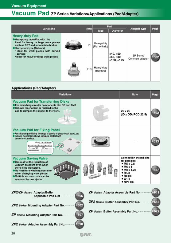
Vacuum Pad ZP Series Variations/Applications (Pad/Adapter)
P.582
P.592
P.593
P.627
P.595
P.602
P.607
P.611
P.613
P.622
P.610
Glass circuit board
ZP2/ZP Series Adapter/Buffer Applicable Pad List
ZP2 Series Mounting Adapter Part No.
ZP Series Mounting Adapter Part No.
ZP2 Series Adapter Assembly Part No.
Connection thread sizefor pad side¡M5 x 0.8¡M6 x 1¡M8 x 1.25¡R1/8¡Rc1/8¡G1/8¡NPT1/8
ZP SeriesCommon adapter
ZP Series Adapter Assembly Part No.
ZP2 Series Buffer Assembly Part No.
ZP Series Buffer Assembly Part No.
Type
H
VariationsPad
DiameterAdapter type Page
ø40, ø50ø63, ø80ø100, ø125
Heavy-duty PadHeavy-duty type (Flat with rib)
Ideal for heavy or large work pieces such as CRT and automobile bodies
Heavy-duty type (Bellows)• Ideal for work pieces with curved
surface• Ideal for heavy or large work pieces
Heavy-duty(Flat with rib)
HB Heavy-duty(Bellows)
Variations Note Page
20 x 25(ID x OD: PCD 22.5)
Vacuum Pad for Transferring DisksFor adsorbing circular components like CD and DVDBellows mechanism is realized in the
pad to dampen the impact to the work.
Vacuum Pad for Fixing PanelFor adsorbing and fixing the stage of panels or glass circuit board, etc.Bellows mechanism allows complete contact with
curved work surface.
Vacuum Saving ValveCan restrict the reduction of
vacuum pressure even when there is no workpiece.No need for switching operation
when changing work piecesMultiple vacuum pads can be
operated by one ejector.
Applications (Pad/Adapter)
Symbol
20

Best Pneumatics 4
P.801 P.802
P.804
AS AKH
ZSE30A
ZSE20
PFMGZ46 GZ46-K2K
¡In the rectangular, compact cylinder CU series which has a high level of mounting precision, a vacuum passage is provided in the rod to facilitate the mounting of a vacuum pad, and save space.
¡Standard vacuum pads (ø2 to ø50) can be mounted.
¡Ideal for adsorption and fixing in place of thin sheets, glass panels, and soft workpieces.Workpieces do not deform since they are adsorbed with multiple micro air vents on the adsorption surface.
¡A high level of machining accuracy.¡Strong adsorption force.
¡Removes water droplets from air by simly installing in vacuum equip-ment connection lines.
¡Effective for removing water drop-lets form the air sucked into vacu-um pumps and ejectors, etc.
ZCUK AMJSP
P.749 P.759 P.773
¡Captures 99.5% of oil mist exhaust-ed form the vacuum pump.
¡Creates a comfortable working en-vironment without oil mist.
¡Captures and separates 99.5% of highly concentrated oil mist with a low flow rate.
¡No need for an exhaust duct from the vacuum pump.
¡A discharge flow rate 4 times the supply air can be generated.
¡A suction flow rate 3 times the sup-ply air can be generated.
¡Contributes to reduction in flow con-sumption if discharge and suction requires flow rate.
¡Prevents vacuum equipment trouble!¡Elements can be reused by wash-
ing them.¡Water drops can be removed¡The bowl is covered with a trans-
parent bowl guard!
AMV ZH--X185AFJ
P.779
Related Equipment for Vacuum System
P.795 P.795 P.796
Adsorption plate Free Mount Cylinderfor Vacuum
Drain Separator for Vacuum
Vacuum FilterP.788
Exhaust Cleaner for Vacuum Pump
P.790Vacuum Flow
Vacuum Regulator Electronic Vacuum Regulator Directional Control Valve
Vacuum Pressure Switch/Flow Switch
Flow Control Equipment Made to Order
Vacuum Pressure Gauge
IRV ITV209 VQD1000-V SY3AR/SY5AR
SJ3A6
Vacuum release valve with throttle valve: SY5A2R········· P.805
Vacuum release valve with throttle valve: SV1A4R-X8··· P.809
Related EquipmentS
erie
sF
eatu
res
Fea
ture
sS
erie
sS
erie
s
21

Vacuum Equipment
Adsorption Transfer System by Ejector
Ejector Module System
Equipment (ejector supply valve, release valve, throttle valve, vacuum pressure switch, and filter) that is needed for the ejector adsorption transfer system has beenintegrated to achieve efficient assembly work and a compact design.
Ejector module/Circuit
Speed controller for release flow adjustment
Release valve
Supply valve
Vacuum pressure switch
Removes dust that is present in air that has been drawn in.
Ejector unit
Filter
Pad
Workpiece
Ejector moduleZK2, ZB, ZR,
ZQ, ZL
Compressor
Refrigerated air dryerIDF series
Flow switchPF2M series
Pressure gauge for vacuumGZ seriesZSE seriesPSE series
Air suction filterZF seriesAMJ seriesAFJ series
Compressed airpreparation filterAFF/AM/AMD
seriesAir filter
AF seriesMist separatorAFM series
RegulatorAR series
P
For the ZK2, ZB, ZR, ZQ and ZL, the combination of single units at right can be integrated into a unit.
22A

Best Pneumatics 4Adsorption Transfer System by Ejector
Equipment such as an ejector is configured as an individual unit. Thus, it is possible to create a flexible system configuration in which the circuit composition and the mounting locations can be selected as desired.
Single Unit System
Controls vacuum generation by turning ON/OFF the supply air to the ejector.
Control ON/OFF of vacuum release air in order to speed up work ejection after vacuum adsorption.
Controls ejection time and prevents blow-away by con-trolling the release flow rate during work ejection.
Acquires a signal indi-cating the specified vacuum pressure has been achieved in vacu-um adsorption, and takes that to be the op-eration start point of the cylinder, etc.
A filter is provided to prevent problems with valves, ejec-tors, sensors and other parts resulting from suction of debris in the environment around the pad.
One-touch fitting
Release valve
Controls compressed airthat is used for ejectinga work piece.
Throttle valve
(Flow control valve)
Supply valve
Controls compressed air to ejector.
Vacuum pressure switchZS seriesZSE seriesPSE series
Detects the vacuumpressure and verifiesthe adsorption.
Pressure gaugefor vacuumGZ seriesZSE seriesPSE series
Pressure gaugefor vacuumVacuum pressureswitchGZ seriesZSE seriesPSE series
Flow switchPF2M series
Air suction filterZF seriesAMJ seriesAFJ series
Removes dust thatis present in air thathas been drawn in.
EjectorZH seriesZU series
Vacuum pad / ZP3 seriesZP2 seriesZP series
Free mount cylinder for vacuumZCUK series
Work piece
23 A

Control unit/Circuit
Vacuum Equipment
Adsorption Transfer System for Vacuum PumpEquipment (vacuum switching valve, release valve, throttle valve, vacuum pressure switch, and filter) that is needed for controlling the vacuum pressure has been integrated to achieve efficient assembly work and a compact design.
Vacuum switch valveVacuum releasevalve
Control unit
Filter
Pad
Workpiece
Vacuum pump
Acquires a signal indicating the speci-fied vacuum pressure has been achieved in vacuum adsorption, and takes that to be the operation start point of the cylinder, etc.
Control ON/OFF of the vacuum sup-plied from the vacuum pump.
A vacuum regulator is provided to prevent pulsation of the vacuum source and maintain vacuum pres-sure at the specified pressure.
Control ON/OFF of vacuum re-lease air in order to speed up work ejection after vacuum adsorption.
Regulator to control vacu-um release pressure.
A filter is provided to prevent problems with valves, ejectors, sensors and other parts re-sulting from suction of debris in the environ-ment around the pad.
Controls ejection time and prevents blow-away by controlling the re-lease flow rate during work ejection.
Control unit / ZK2ZBZR100ZQVQD1000-V
Vacuum regulator / IRV seriesDirect operated vacuum regulator that regulates vacuum pressureElectronic vacuum regulator / ITV209 seriesControls vacuum pressure by external electric signal.
Vacuum pump
∗ If the control unit is not used, it is possible to configure the system by using individual units such as a switching valve, release valve, filter, pressure switch, etc.
Pressure gaugefor vacuumVacuum pressureswitchGZ seriesZSE seriesPSE series
Flow switchPF2M series
Vacuum pad / ZP series Free mount cylinder for vacuumZCUK series
Work piece
Compressor
Refrigerated air dryerIDF series
Air filterAF series
Mist separatorAFM series
RegulatorAR series
For the ZK2, ZB, ZR, ZQ and VQD, the combination of single units at right can be integrated into a unit
Removes dust that is present in air that has been drawn in.
Air suction filterZF seriesAMJ seriesAFJ series
Vacuum pressure switch
P
24
Compressed air preparation filterAFF/AM/AMD
series
A

1 P.26
3 P.33
4 P.33
5 P.34
6 P.36
7 P.40
8 P.41
2 P.26
C O N T E N T S
Vacuum Pad Selection Procedures Points for Selecting Vacuum Pads A. Theoretical Lifting Force B. Shear Force and Moment Applied to Vacuum Pad Lifting Force and Vacuum Pad Diameter 1. Theoretical Lifting Force Vacuum Pad Type Vacuum Pad Material Rubber Material and Properties Color and Identification Buffer Attachment Pad Selection by Workpiece Type Vacuum Pad Durability
Calculating Vacuum Ejector and Switching Valve Size with the Formula
Leakage Volume from Conductance of Workpiece Leakage Volume from Adsorption Test
Relationship between Vacuum Pressure and Response Time after Supply Valve (Switching Valve) is Operated Calculating Adsorption Response Time with the Formula Adsorption Response Time from the Selection Graph
Safety Measures Precautions on Vacuum Equipment Selection Vacuum Ejector or Pump and Number of Vacuum Pads Vacuum Ejector Selection and Handling Precautions Supply Pressure of Vacuum Ejector Timing for Vacuum Generation and Suction Verification A. Timing for Vacuum Generation B. Suction Verification C. Set Pressure for Vacuum Pressure Switch Dust Handling of Vacuum Equipment
Transfer of Semiconductor Chips
Selection Graph Glossary of Terms Countermeasures for Vacuum Adsorption System Problems (Troubleshooting) Non-conformance Examples Time of Replacement of Vacuum Pad
Features and Precautions for Vacuum Adsorption
Selection of Vacuum Ejector and Vacuum Switching Valve
Leakage Volume during Workpiece Adsorption
Adsorption Response Time
Precautions on Vacuum Equipment Selection and SMC’s Proposal
Vacuum Equipment Selection Example
Data
Vacuum Pad Selection
Vacuum Equipment
Model Selection
25

1
2
Model Selection
Features and Precautions for Vacuum Adsorption
Vacuum Pad Selection Procedures1) Fully taking into account the balance of a workpiece, identify the adsorption positioning, number of pads and applicable pad
diameter (or pad area).
2) Find the theoretical lifting force from the identified adsorption area (pad area x number of pads) and vacuum pressure, and then find the lifting force considering actual lifting and safety factor of transfer condition.
3) Determine a pad diameter (or pad area) that is sufficient to ensure the lifting force is greater than the workpiece mass.
4) Determine the pad type and materials, and the necessity of buffer based on the operating environment, and the workpiece shape and materials.
The above shows selection procedures for general vacuum pads; thus, they will not be applicable for all pads. Customers are required to conduct a test on their own and to select applicable adsorption conditions and pads based on the test results.
Points for Selecting Vacuum PadsA. Theoretical Lifting Force
• The theoretical lifting force is determined by vacuum pressure and adsorption area of the vacuum pad. • Since the theoretical lifting force is the value measured at the static state, the safety factor responding to the actual
operating conditions must be estimated in the actual operation. • It is not necessarily true that higher vacuum pressure is better. Extremely high vacuum pressure may cause problems.
• When the vacuum pressure is unnecessarily high, pads are likely to be worn out earlier or cracked, causing shorter pad service life.Doubling the vacuum pressure makes the theoretical lifting force double, while to doubling the pad diameter makes the theoretical lifting force quadruple.
• When the vacuum pressure (set pressure) is high, it makes not only response time longer, but also the necessary energy to generate a vacuum larger.
Example) Theoretical lifting force = Pressure x Area
Pad diameterArea (cm2) Vacuum pressure
[-40 kPa]Vacuum pressure
[-80 kPa]
ø20
ø40
3.14
12.56
Theoretical lifting force12 N
Theoretical lifting force50 N
Theoretical lifting force25 N
Theoretical lifting force100 N
4 times
2 times
Vacuum adsorption system as a method to hold a workpiece has the following features.
• Easy construction• Compatible with any place where adsorption is possible.• No need for accurate positioning• Compatible with soft and easily-deformed work pieces
However, special care is required in the following conditions.
• Workpiece may drop under certain conditions since it is transferred being adsorbed. • Liquid or foreign matter around the workpiece may be sucked into the equipment.• Large adsorption area is necessary to get large gripping force.• Vacuum pad (rubber) may deteriorate.
Fully understand the features above and select the equipment that suits your operating conditions.
Vacuum Pad Selection
26

B. Shear Force and Moment Applied to Vacuum Pad
• Vacuum pads are not resistant to shear force (parallel force with adsorption surface) and moment.• Minimize the moment applied to the vacuum pad with the position of the workpiece center of gravity in mind.• The acceleration rate of the movement must be as small as possible, and make sure to take into consideration the wind
pressure and impact. If measures to slow down the acceleration rate are introduced, safety to prevent the workpiece from dropping will improve.
• Avoid lifting the workpiece by adsorbing the vertical side with a vacuum pad (vertical lifting) if possible. When it is unavoidable, a sufficient safety factor must be secured.
To lift a workpiece vertically, make sure to take into consideration the acceleration rate, wind pressure, impact, etc., in addition to the mass of the workpiece. (Refer to Fig. 1)Because the pads are susceptible to moments, mount the pad so as not to allow the workpiece to create a moment. (Refer to Fig. 2)When a workpiece that is suspended horizontally is moved laterally, the workpiece could shift depending on the extent of the acceleration rate or the size of the friction coefficient between the pad and the workpiece. Therefore, the acceleration rate of the lateral movement must be minimized. (Refer to Fig. 3)
Make sure that the pad's suction surface is not larger than the surface of the workpiece to prevent vacuum leakage and unstable picking.
As a rule, the unit must be installed horizontally. Although a diagonal or a vertical installation should be avoided whenever possible, if the unit must be installed in such a manner, be certain to guarantee guide and absolute safety.
If multiple pads are used for transferring a flat object with a large surface area, properly allocate the pads to maintain balance. Also make sure that the pads are aligned properly to prevent them from becoming disengaged along the edges.
Provide an auxiliary device (example: a guide for preventing the workpieces from dropping) as necessary.
Horizontal lifting Vertical lifting
Lifting Force, Moment, Horizontal Force
Loading by acceleration and wind pressure lifting
Lifting direction
Pad
Fig
. 1
Pad positioning
Pad Pad
Caution for friction force between pad andworkpiece
Pad
Balance of Pad and Workpiece
Pad
Caution
Guide for drop prevention
Pad
Caution
Guide for drop prevention
Mounting Position
Pad
Guide
Fig
. 2
Fig
. 3
Model Selection
27

Pad diameter (mm)Pad area S (cm2)
ø80.50
ø10 ø13 ø16 ø20 ø25 ø32 ø40 ø500.79 1.33
ø1.50.02
ø4 ø60.13 0.28 2.01 3.14 4.91 8.04 12.6 19.6
Vacuumpressure
(kPa)
(N)
−85−80−75−70−65−60−55−50−45−40
0.150.140.130.120.110.110.100.090.080.07
ø20.030.270.250.240.220.200.190.170.160.140.13
ø3.50.100.820.770.720.670.630.580.530.480.430.38
1.071.000.940.880.820.750.690.630.570.50
2.402.262.121.981.841.701.551.411.271.13
4.24.03.73.53.23.02.72.52.22.0
6.66.25.85.55.14.74.33.93.53.1
111010
9.3 8.6 8.0 7.3 6.7 6.0 5.3
1716151413121110
9.0 8.0
26252322201817151412
41393634312927242219
68646056524844403632
106100
94 87 81 75 69 62 56 50
166157147137127117107
98 88 78
Pad diameter (mm)Pad area S (cm2)
ø125122.7
ø150 ø250 ø300 ø340176.6
ø6331.2
ø80 ø10050.2 78.5 490.6 706.5 907.5
Vacuumpressure
(kPa)
−85−80−75−70−65−60−55−50−45−40
265250234218203187172156140125
427402377351326301276251226201
667628589550510471432393353314
1043 982 920 859 798 736 675 614 552 491
150114131325123611481060 971 883 795 706
4170392536803434318929442698245322081962
ø200314.02669251223552198204118841727157014131256
6005565252994946459242393886353331792826
7714726068066353589954454991453840843630
Pad diameter (mm)Pad area S (cm2) 0.44 0.52 0.76
2 x 40.07
3.5 x 7 4 x 10 5 x 10 6 x 10 4 x 20 5 x 20 6 x 20 8 x 20 4 x 30 5 x 30 6 x 30 8 x 300.21 0.36 0.94 1.12 1.46 1.16
Vacuumpressure
(kPa)
−85−80−75−70−65−60−55−50−45−40
0.600.560.530.490.460.420.390.350.320.28
1.791.681.581.471.371.261.161.050.950.84
3.02.82.72.52.32.11.91.81.61.4
3.73.53.33.02.82.62.42.21.91.7
4.44.13.93.63.33.12.82.62.32.0
6.46.05.75.34.94.54.13.83.43.0
7.97.57.06.56.15.65.14.74.23.7
9.58.98.47.87.26.76.15.65.04.4
12.411.610.910.2 9.4 8.7 8.0 7.3 6.5 5.8
9.89.28.78.17.56.96.35.85.24.6
1.4412.211.510.810.0 9.3 8.6 7.9 7.2 6.4 5.7
1.7214.613.712.912.011.110.3 9.4 8.6 7.7 6.8
2.2619.218.016.915.814.613.512.411.310.1 9.0
30 x 5013.07112105 98 92 85 79 72 66 59 53
(N)
(N)
Horizontal lifting Vertical lifting
This type of application should basically be avoided.
Pad Diameter (ø1.5 to ø50)
Pad Diameter (ø63 to ø340)
Oval Pad (2 x 4 to 8 x 30, 30 x 50)
W = P x S x 0.1 x 1t
WPSt
Lifting Force and Vacuum Pad Diameter
1. Theoretical Lifting Force
• Set the vacuum pressure below the pressure that has been stabilized after adsorption.• However, when a workpiece is permeable or has a rough surface, note that the vacuum pressure drops since the workpiece
takes air in. In such a case, carry out an adsorption test for confirmation.• The vacuum pressure when using an ejector is approximately –60 kPa as a guide.
The theoretical lifting force of a pad can be found by calculation or from the theoretical lifting force table.
: Lifting force (N): Vacuum pressure (kPa): Pad area (cm2): Safety factor Horizontal lifting: 4 or more Vertical lifting: 8 or more
The theoretical lifting force (not including the safety factor) is found from the pad diameter and vacuum pressure. The required lifting force is then found by dividing the theoretical lifting force by the safety factor t.
Lifting force = Theoretical lifting force ÷ t
Model Selection
PadCalculation
Theoretical Lifting Force
(1) Theoretical Lifting Force (Theoretical lifting force = P x S x 0.1)
28
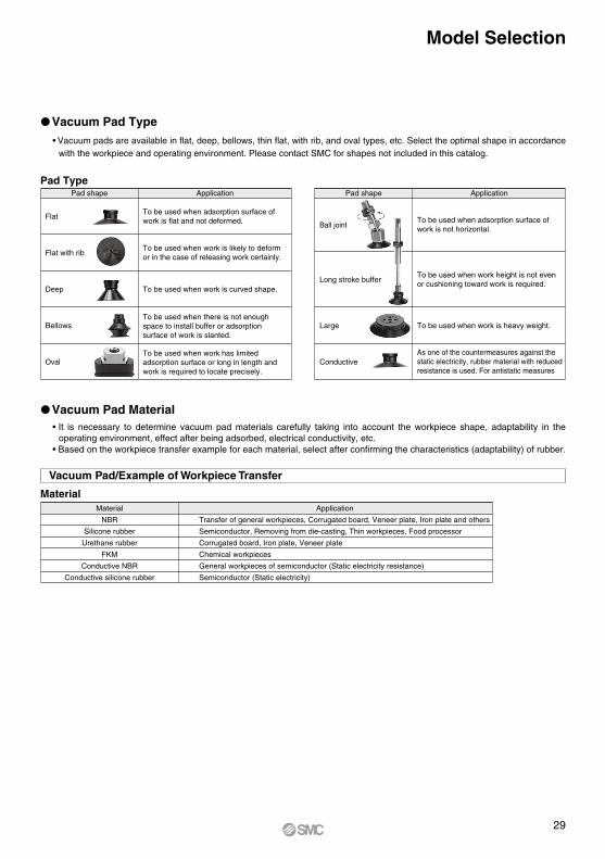
ApplicationPad shape
FlatTo be used when adsorption surface of work is flat and not deformed.
Flat with ribTo be used when work is likely to deform or in the case of releasing work certainly.
Deep To be used when work is curved shape.
BellowsTo be used when there is not enough space to install buffer or adsorption surface of work is slanted.
OvalTo be used when work has limited adsorption surface or long in length and work is required to locate precisely.
ApplicationPad shape
Ball jointTo be used when adsorption surface of work is not horizontal.
Long stroke bufferTo be used when work height is not even or cushioning toward work is required.
Large To be used when work is heavy weight.
ConductiveAs one of the countermeasures against the static electricity, rubber material with reduced resistance is used. For antistatic measures
Pad Type
Vacuum Pad Type• Vacuum pads are available in flat, deep, bellows, thin flat, with rib, and oval types, etc. Select the optimal shape in accordance
with the workpiece and operating environment. Please contact SMC for shapes not included in this catalog.
Vacuum Pad Material• It is necessary to determine vacuum pad materials carefully taking into account the workpiece shape, adaptability in the
operating environment, effect after being adsorbed, electrical conductivity, etc. • Based on the workpiece transfer example for each material, select after confirming the characteristics (adaptability) of rubber.
Vacuum Pad/Example of Workpiece Transfer
MaterialApplication Material
NBR Transfer of general workpieces, Corrugated board, Veneer plate, Iron plate and others
Silicone rubber Semiconductor, Removing from die-casting, Thin workpieces, Food processor
Urethane rubber Corrugated board, Iron plate, Veneer plate
FKM Chemical workpieces
Conductive NBR General workpieces of semiconductor (Static electricity resistance)
Conductive silicone rubber Semiconductor (Static electricity)
Model Selection
29

Pure gum property (specific gravity)
Impact resilience
Abrasion resistance
Tear resistance
Flex crack resistance
Volume resistivity (Ωcm)
Heat aging
Weather resistance
Ozone resistance
Gas permeability resistance
Gasoline/Gas oil
Benzene/Toluene
Alcohol
Ether
Ketone (MEK)
Ethyl acetate
Water
Organic acid
Strong alkali
Weak alkali
1.00-1.20
120
0
—
to
to
to
to to
0.95-0.98
to to to
200
−30
—
to to
to
1.00-1.30
60
0
—
to
to
to
1.80-1.82
250
0
—
to
to
to
to
0.86-0.87
150
−20
—
to
1.00-1.20
100
0
104 or less
to
to
to
to to
0.95-0.98
to to to
200
−10
104 or less
to to
to
∗ The indicated physical properties, chemical resistance and other numerical values are only approximate values used for reference. They are not guaranteed values. · The above general characteristics may change according to the working conditions and the working environment. · When determining the material, carry out adequate confirmation and verification in advance. · SMC will not bear responsibility concerning the accuracy of data or any damage arising from this data.
Note) The hardness of rubber shall conform to JIS K 6253. The hardness of sponge shall conform to SRIS 0101.
0.161g/cm3
to
120
−20
3.8 x 10⁴
0.4g/cm3
to
180
−30
4.8 x 10⁴
Rubber Material and Properties
1.15-1.25
150
−40
—
to
to to to
to
Color and Identification (ZP/ZP2)
Color and Identification (ZP3)
Identification(Dot or stamp)
Color of rubber
A60/S A50/S A50/S A50/S A50/S 20 15Rubber hardness HS (±5°) A50/S
Other than Heavy duty A40/S
Heavy duty A50/SA60/S
= Excellent --- Not affected at all, or almost no effect= Good --- Affected a little, but adequate resistance depending on conditions= Better not to use if possible= Unsuitable for usage. Severely affected.
Model Selection
Generalname NBR
(Nitrile rubber)Silicone rubber Urethane rubber
FKM(Fluororubber)
Conductive NBR(Nitrile rubber)
Conductivesilicone rubber
Color of rubber
Identification (Dot)
Rubber hardness HS (±5°)
Black White Brown Black Black Black
— — —
A60/S
· Silver 1 dot · Pink 1 dot· Green 1 dot
Main features
NBR(Nitrilerubber)
Siliconerubber
Good oil resistance, abrasion resistance, and aging resistance
Excellent heat resistance, and cold resistance
Urethanerubber
Excellent mechanical strength
FKM(Fluororubber)
Best heat resistance, and chemical resistance
EPR(Ethylene-propylene
rubber)
Good aging resistance, ozone resistance, and electrical properties
ConductiveNBR
(Nitrilerubber)
Good oil resistance, abrasion resistance, and aging resistance. Conductive
Conductivesiliconerubber
Very excellent heat resistance, and cold resistance. Conductive
ConductiveCR sponge(Chloroprene
sponge)
Excellent impact resilience, and sound insulation. Flame retardance
Conductivesiliconesponge
Excellent heat insulation, and impact resilience
CR(Chloroprene
rubber)
Well balanced weather resistance, ozone resistance, and chemical resistance
Generalname
Black White Brown Black Black Black Black Black Black Black
— — —· Silver 1 dot · Silver 2 dots
— —· Green 1 dot·
· Red 1 dot·
·
Maximum operationtemperature °CMinimum operationtemperature °C
Organic acid of high concentration Organic acid of lowconcentration
Generalname
Phys
ical p
ropert
ies
of ble
nded g
um
Chem
ical r
esi
stance
Oil
resi
stance
Alk
alin
e r
esi
stance
Aci
d r
esi
stance
NBR(Nitrilerubber)
Siliconerubber
Urethanerubber
FKM(Fluoro-rubber)
EPR(Ethylene-propylene
rubber)
ConductiveNBR
(Nitrilerubber)
Conductivesiliconerubber
ConductiveCR sponge(Chloroprene
sponge)
Conductivesiliconesponge
CR(Chloroprene
rubber)
30

Model Selection
If a soft workpiece such as vinyl, paper, or thin sheet is picked up, the vacuum pressure could cause the workpiece to deform or wrinkle. In such a case, it will be necessary to use a small pad or a ribbed pad and reduce the vacuum pressure.
When pushing a pad to a workpiece, make sure not to apply an impact or a large force which would lead to premature deformation, cracking, or wearing of the pad. The pad should be pushed against the workpiece to the extent that its skirt portion deforms or that its ribbed portion comes into slight contact with the workpiece.Especially, when using a smaller diameter pad, make sure to locate it correctly.
Buffer Attachment• Choose buffer type when the workpieces are of varying heights, the workpieces are fragile, or you need to reduce the impact
to the pad. If rotation needs to be limited, use non-rotating buffer.
When the workpieces are of varying heights, use the buffer type pad with built-in spring. The spring creates a cushion effect between the pad and the workpieces. If rotation needs to be limited further, use non-rotating buffer type.
Pad Selection by Workpiece Type• Carefully select a pad for the following workpieces.
To pick a permeable workpiece such as paper, select a pad with a small diameter that is sufficient to lift the workpiece. Because a large amount of air leakage could reduce the pad’s suction force, it may be necessary to increase the capacity of an ejector or vacuum pump or enlarge the conductance area of the piping passage.
When a workpiece with a large surface area such as sheet glass or PCB is suspended, the workpiece could move in a wavelike motion if a large force is applied by wind pressure or by an impact. Therefore, it is necessary to ensure the proper allocation and size of pads.
2. Flat Plate Workpiece
Unsteady Distance between Pad and Workpiece
1. Porous Workpiece
3. Soft Workpiece
Porous work
Vinyl, paper, etc.
Pad
4. Impact to Pad
Decide the positionnot to strike
Plate glass, circuit board, etc.
31
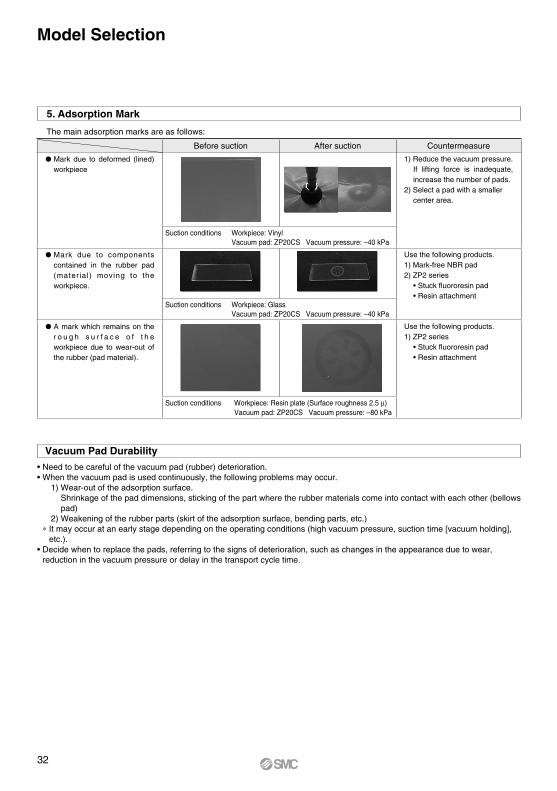
The main adsorption marks are as follows:
• Need to be careful of the vacuum pad (rubber) deterioration.• When the vacuum pad is used continuously, the following problems may occur.
1) Wear-out of the adsorption surface. Shrinkage of the pad dimensions, sticking of the part where the rubber materials come into contact with each other (bellows pad)
2) Weakening of the rubber parts (skirt of the adsorption surface, bending parts, etc.)* It may occur at an early stage depending on the operating conditions (high vacuum pressure, suction time [vacuum holding],
etc.).• Decide when to replace the pads, referring to the signs of deterioration, such as changes in the appearance due to wear,
reduction in the vacuum pressure or delay in the transport cycle time.
Vacuum Pad Durability
Before suction After suction Countermeasure
P Mark due to deformed (lined) workpiece
1) Reduce the vacuum pressure.If lifting force is inadequate, increase the number of pads.
2) Select a pad with a smaller center area.
Suction conditions Workpiece: Vinyl Vacuum pad: ZP20CS Vacuum pressure: –40 kPa
P Mark due to components contained in the rubber pad (material) moving to the workpiece.
Use the following products.1) Mark-free NBR pad2) ZP2 series
• Stuck fluororesin pad• Resin attachment
Suction conditions Workpiece: Glass Vacuum pad: ZP20CS Vacuum pressure: –40 kPa
P A mark which remains on the r o u g h s u r f a c e o f t h e workpiece due to wear-out of the rubber (pad material).
Use the following products.1) ZP2 series
• Stuck fluororesin pad• Resin attachment
Suction conditions Workpiece: Resin plate (Surface roughness 2.5 m) Vacuum pad: ZP20CS Vacuum pressure: –80 kPa
Model Selection
5. Adsorption Mark
32
Selection of Vacuum Ejector and Vacuum Switching Valve3
Leakage Volume during Workpiece Adsorption4
Leakage Volume from Conductance of Workpiece
Leakage Volume from Adsorption Test
Air could be drawn in depending on the type of workpiece. As a result, the vacuum pressure in the pad becomes reduced and the amount of vacuum that is necessary for adsorption cannot be attained. When this type of workpiece must be handled, it is necessary to select the proper size of the ejector and the vacuum switching valve by taking into consideration the amount of air that could leak through the workpiece.
Leakage volume QL = 55.5 x CL
QL: Leakage volume L/min (ANR) CL: Conductance between workpiece and pad, and workpiece opening area [dm3/(s·bar)]
As described in the illustration below, pick up the workpiece with the ejector, using an ejector, pad and a vacuum gauge.
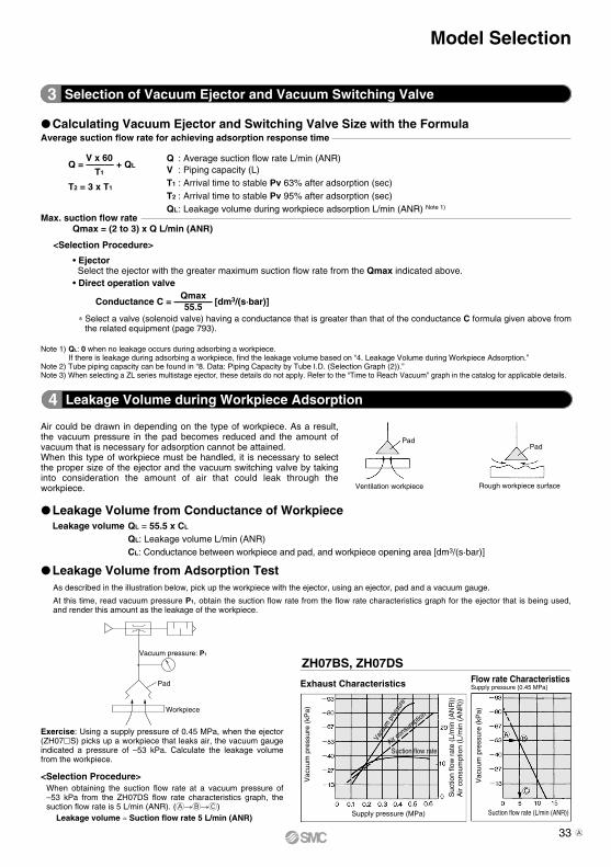
At this time, read vacuum pressure P1, obtain the suction flow rate from the flow rate characteristics graph for the ejector that is being used, and render this amount as the leakage of the workpiece.
Exercise: Using a supply pressure of 0.45 MPa, when the ejector (ZH07S) picks up a workpiece that leaks air, the vacuum gauge indicated a pressure of –53 kPa. Calculate the leakage volume from the workpiece.
<Selection Procedure>When obtaining the suction flow rate at a vacuum pressure of –53 kPa from the ZH07DS flow rate characteristics graph, the suction flow rate is 5 L/min (ANR).
Leakage volume ≈ Suction flow rate 5 L/min (ANR)
PadPad
Ventilation workpiece Rough workpiece surface
Vacuum pressure: P1
Pad
Workpiece
Calculating Vacuum Ejector and Switching Valve Size with the FormulaAverage suction flow rate for achieving adsorption response time
Max. suction flow rateQmax = (2 to 3) x Q L/min (ANR)
<Selection Procedure>
• EjectorSelect the ejector with the greater maximum suction flow rate from the Qmax indicated above.
• Direct operation valve
∗ Select a valve (solenoid valve) having a conductance that is greater than that of the conductance C formula given above from the related equipment (page 793).
Q : Average suction flow rate L/min (ANR)V : Piping capacity (L)T1 : Arrival time to stable Pv 63% after adsorption (sec)T2 : Arrival time to stable Pv 95% after adsorption (sec)QL : Leakage volume during workpiece adsorption L/min (ANR) Note 1)
Q = ——— + QL
T2 = 3 x T1
V x 60
T1
Conductance C = ———— [dm3/(s·bar)]Qmax55.5
Note 1) QL: 0 when no leakage occurs during adsorbing a workpiece.If there is leakage during adsorbing a workpiece, find the leakage volume based on “4. Leakage Volume during Workpiece Adsorption.”
Note 2) Tube piping capacity can be found in “8. Data: Piping Capacity by Tube I.D. (Selection Graph (2)).”Note 3) When selecting a ZL series multistage ejector, these details do not apply. Refer to the “Time to Reach Vacuum” graph in the catalog for applicable details.
Suction flow rate
Vacu
um p
ress
ure
Air consu
mption
ZH07BS, ZH07DSFlow rate CharacteristicsSupply pressure 0.45 MPaExhaust Characteristics
Supply pressure (MPa) Suction flow rate (L/min (ANR))
Vac
uum
pre
ssur
e (k
Pa)
Vac
uum
pre
ssur
e (k
Pa)
Suc
tion
flow
rat
e (L
/min
(A
NR
))A
ir co
nsum
ptio
n (L
/min
(A
NR
))
Model Selection
33 A

Adsorption Response Time5
When a vacuum pad is used for the adsorption transfer of a workpiece, the approximate adsorption response time can be obtained (the length of time it takes for the pad’s internal vacuum pressure to reach the pressure that is required for adsorption after the supply valve vacuum switching valve has been operated). An approximate adsorption response time can be obtained through formulas and selection graphs.However, when selecting a ZL series multistage ejector, these details do not apply. Refer to the “Time to Reach Vacuum” graph in the catalog for applicable details.
Relationship between Vacuum Pressure and Response Time after Supply Valve (Switching Valve) is Operated
The relationship between vacuum pressure and response time after the supply valve (switching valve) is operated as shown below.
Vacuum Pressure and Response Time after Supply Valve (Switching Valve) is Operated
Calculating Adsorption Response Time with the FormulaAdsorption response times T1 and T2 can be obtained through the formulas given below.
For the conductance, the equivalent conductance can be found in “8. Data: Conductance by Tube I.D. (Selection Graph (3)).”
T1 : Arrival time to 63% of final vacuum pressure Pv (sec)T2 : Arrival time to 95% of final vacuum pressure Pv (sec)Q1
: Average suction flow rate L/min [ANR]
Calculation of average suction flow rate • Ejector
Q1 = (1/2 to 1/3) x Ejector max. suction flow rate L/min [ANR] • Vacuum pump
Q1 = (1/2 to 1/3) x 55.5 x Conductance of vacuum pump [dm3/(s·bar)]D : Piping diameter (mm)L : Length from ejector and switch valve to pad (m)V : Piping capacity from ejector and switching valve to pad (L)Q2 : Max. flow from ejector and switching valve to pad by piping system
Q2 = C x 55.5 L/min [ANR]Q : Smaller one between the Q1 and Q2 L/min [ANR]C : Conductance of piping [dm3/(s·bar)]
Adsorption response time T1 = ———
Adsorption response time T2 = 3 x T1
Piping capacity
V = —— D2 x L x –––– (L)
V x 60Q
3.144
11000
Vacuum System Circuit
Pv: Final vacuum pressureT1 : Arrival time to 63% of final vacuum pressure PvT2 : Arrival time to 95% of final vacuum pressure Pv
Arrival time (sec)
Supply valve(Switching valve)
operation
Vac
uum
pre
ssur
e (P
)PP
Switching valveSwitching valve
Pad Pad
WorkWork
Model Selection
34A
Max
. suc
tion
flow
rat
e Q
(L/
min
(A
NR
))
Piping capacity
Arrival time of vacuum pressure (63%) T1 (sec)
Arrival time of vacuum pressure (95%) T2 (sec)
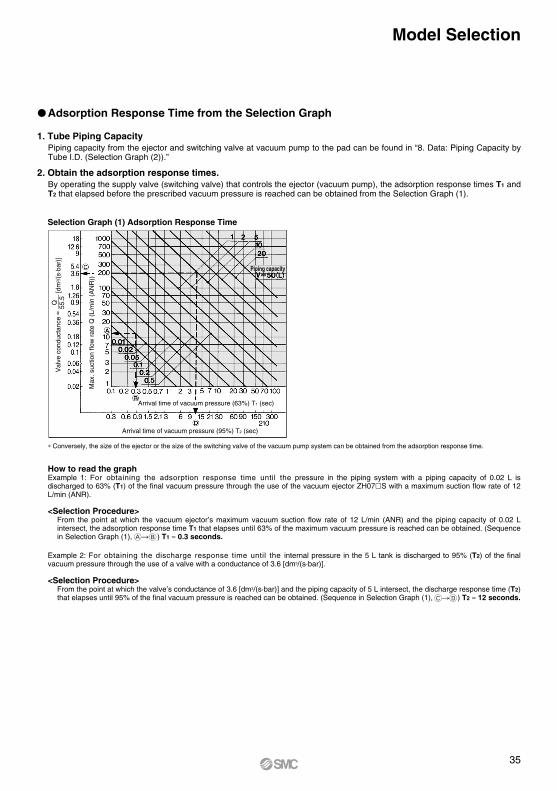
Adsorption Response Time from the Selection Graph
1. Tube Piping CapacityPiping capacity from the ejector and switching valve at vacuum pump to the pad can be found in “8. Data: Piping Capacity by Tube I.D. (Selection Graph (2)).”
2. Obtain the adsorption response times.By operating the supply valve (switching valve) that controls the ejector (vacuum pump), the adsorption response times T1 and T2 that elapsed before the prescribed vacuum pressure is reached can be obtained from the Selection Graph (1).
Val
ve c
ondu
ctan
ce =
Q55
.5[d
m3 /(
s·ba
r)]
Selection Graph (1) Adsorption Response Time
∗ Conversely, the size of the ejector or the size of the switching valve of the vacuum pump system can be obtained from the adsorption response time.
How to read the graphExample 1: For obtaining the adsorption response time until the pressure in the piping system with a piping capacity of 0.02 L is discharged to 63% (T1) of the final vacuum pressure through the use of the vacuum ejector ZH07S with a maximum suction flow rate of 12 L/min (ANR).
<Selection Procedure>From the point at which the vacuum ejector’s maximum vacuum suction flow rate of 12 L/min (ANR) and the piping capacity of 0.02 L intersect, the adsorption response time T1 that elapses until 63% of the maximum vacuum pressure is reached can be obtained. (Sequence in Selection Graph (1), ) T1 ≈ 0.3 seconds.
Example 2: For obtaining the discharge response time until the internal pressure in the 5 L tank is discharged to 95% (T2) of the final vacuum pressure through the use of a valve with a conductance of 3.6 [dm3/(s·bar)].
<Selection Procedure>From the point at which the valve’s conductance of 3.6 [dm3/(s·bar)] and the piping capacity of 5 L intersect, the discharge response time (T2) that elapses until 95% of the final vacuum pressure is reached can be obtained. (Sequence in Selection Graph (1), ) T2 ≈ 12 seconds.
Model Selection
35

P
P PP
Vacuum line
PPP
Tank
PPP
P P
When more than one pad is attached to a single ejector, if one of the workpieces becomes detached, the vacuum pressure will drop, causing other workpieces to become detached. Therefore, the countermeasures listed below must be taken.• Adjust the needle valve to minimize the
pressure fluctuation between adsorption and non-adsorption operations.
• Provide a vacuum switching valve to each individual pad to minimize the influences on other pads if an adsorption error occurs.
Ideally, one pad should be used for each line.
When more than one pad is attached to a single vacuum line, take the countermeasures listed below.• Adjust the needle valve to minimize the
pressure fluctuation between adsorption and non-adsorption operation.
• Include a tank and a vacuum pressure reduction valve (vacuum pressure regulator valve) to stabilize the source pressure.
• Provide a vacuum switching valve to each individual pad to minimize the influences on other pads if an adsorption error occurs.
Ideally, one pad should be used for each ejector.
Vacuum Ejector or Pump and Number of Vacuum PadsEjector and number of pads Vacuum pump and number of pads
Precautions on Vacuum Equipment Selection and SMC’s Proposal6
Safety Measures• Make sure to provide a safe design for a vacuum pressure drop due to a disruption of power supply, or a lack of supply air.
Drop prevention measures must be taken in particular when dropping a workpiece presents some degree of danger.
Precautions on Vacuum Equipment Selection
• During the adsorption and transfer of a workpiece, verification of the vacuum switch is recommended.
• In addition, visually verify the vacuum gauge when handling a heavy or a hazard-ous item.
• Install a filter (ZFA, ZFB, ZFC series) before the pressure switch if the ambient air is of low quality.
Use a suction filter (ZFA, ZFB, ZFC series) to protect the switching valve and to prevent the ejector from becoming clogged. Also, a suction filter must be used in a dusty environment. If only the unit's filter is used, it will become clogged quickly.
As a countermeasure for power outages, select a supply valve that is normally open or one that is equipped with a self-holding function.
Be aware that the composite conductance consisting of the areas from the pad to the ejector of a vacuum switching valve does not decrease.
For the release valve, select a 2/3 port valve with a low vacuum specification. Also, use a needle valve to regulate the release flow rate.
Model Selection
36

P
Vacuumpressure
Leakage
Model Selection
• If the vacuum ejector makes an intermittent noise (abnormal noise) from exhaust at a certain supply pressure, the vacuum pressure will not be stable. It will not be any problem if the vacuum ejector is used under this condition. However, if the noise is disturbing or might affect the operation of the vacuum pressure switch, lower or raise supply pressure a little at a time, and use in an air pressure range that does not produce the intermittent noise.
Supply Pressure of Vacuum Ejector• It is recommended to use the vacuum ejector at the standard supply pressure.
The maximum vacuum pressure and suction flow rate can be obtained when the vacuum ejector is used at the standard supply pressure, and as a result, adsorption response time also improves. From the viewpoint of energy-saving, it is the most effective to use the ejector at the standard supply pressure. Since using it at an excessive supply pressure may cause the ejector performance to lower, it is recommended to use at the standard supply pressure.
The vacuum pressure varies in accordance with the leakage volumes indicated in the above diagrams.If the leakage volume is 30 L/min (ANR), the vacuum pressure of the S type is –20 kPa q → w → e, and for the L type it is –33 kPa q' → w' → e'. If the leakage volume is 5 L/min (ANR), the vacuum pressure of the S type is –80 kPa r → t → y, and for the L type it is –47 kPa r' → t' → y'. Thus, if the leakage volume is 30 L/min (ANR) the L type can attain a higher vacuum pressure, and if the leakage volume is 5 L/min (ANR), the S type can attain a higher vacuum pressure.Thus, during the selection process, make sure to take the flow rate characteristics of the high vacuum type (S type) and the high flow type (L type) into consideration in order to select the type that is optimal for your application.
Vacuum Ejector Selection and Handling Precautions
Ejector Selection
There are 2 types of ejector flow rate characteristics: the high vacuum type (S type) and the high flow type (L type). During the selection, pay particular attention to the vacuum pressure when adsorbing workpieces that leak.
High Vacuum TypeFlow Rate Characteristics/ZH13S
High Flow TypeFlow Rate Characteristics/ZH13L
Vac
uum
pre
ssur
e (k
Pa)
Vac
uum
pre
ssur
e (k
Pa)
Suction flow rate (L/min (ANR)) Suction flow rate (L/min (ANR))
Ejector Nozzle Diameter Selection
If a considerable amount of leakage occurs between the workpiece and the pad, resulting in incomplete adsorption, or to shorten the adsorption and transfer time, select an ejector nozzle with a larger diameter from the ZH, ZR, or ZL series.
Manifold Use
Individual exhaust Centralized exhaust
If there are a large number of ejectors that are linked on a manifold and operate simultaneously, use the built-in silencer type or the port exhaust type.
If there are a large number of ejectors that are linked on a manifold, which exhaust collectively, install a silencer at both ends. If the exhaust must be discharged outdoors through piping, make the diameter of the piping larger to control its back pressure to 5 kPa or less so that the back pressure will not affect the operation of the ejectors.
37

During adsorption During vacuum release
Cylinder UP
Cylinder DOWN
Cylinder switch
Supply valve
Release valve
V port vacuum pressure
Vacuum pressure switch
Vacuum pressure switch set value
By lowering the setting of the vacuum switch, the takt time can be shortened.
Atmospheric pressure
Vacuumpressure atoperation
When adsorbing and transferring a workpiece, verify at the vacuum pressure switch as much as possible (In addition, visually verify the vacuum gauge, especially when handling a heavy or a hazardous item.).
Approx. ø1 adsorption nozzleThe difference in pressure between ON and OFF becomes small depending on the capacity of the ejector and vacuum pump. In such a case, it is necessary to use the digital pressure switch ZSE10 or ZSE30A with a fine smallest settable increment or a flow switch for flow rate detection. Note) • A vacuum generator with a large suction capacity will not
be detected properly, so an ejector with an appropriate capacity must be selected.
• Since the hysteresis is small, vacuum pressure must be stabilized.
Vacuum pressure switchZSE10, ZSE30A
Flow sensorPFMV
Vacuum pressure gaugeGZ46
Refer to the Best Pneumatics No. 8 for details.
Timing Chart Example
Timing for Vacuum Generation and Suction Verification
A. Timing for Vacuum GenerationThe time for opening/closing the valve will be counted if a vacuum is generated after the adsorption pad descends to adsorb a workpiece. Also, there is a timing delay risk for the generating vacuum since the operational pattern for the verification switch, which is used for detecting the descending vacuum pad, is not even.To solve this issue, we recommend that vacuum be generated in advance, before the vacuum pad begins to descend to the workpiece. Adopt this method after confirming that there will be no misalignment resulting from the workpiece’s light mass.
B. Suction VerificationWhen lifting the vacuum pad after absorbing a workpiece, confirm that there is a suction verification signal from the vacuum pressure switch, before the vacuum pad is lifted. If the vacuum pad is lifted, based on the timing of a timer, etc., there is a risk that the workpiece may be left behind.In general adsorption transfer, the time for adsorbing a workpiece is slightly different since the position of the vacuum pad and the workpiece are different after every operation. Therefore, program a sequence in which the suction completion is verified by a vacuum pressure switch, etc. before moving to the next operation.
C. Set Pressure for Vacuum Pressure SwitchSet the optimum value after calculating the required vacuum pressure for lifting a workpiece.If a higher pressure than required is set, there is a possibility of being unable to confirm the suction even though the workpiece is adsorbed. This will result in a suction error.When setting vacuum pressure switch set values, you should set using a lower pressure, with which a workpiece can be adsorbed, only after considering the acceleration or vibration when a workpiece is transferred. The set value of the vacuum pressure switch shortens the time to lift a workpiece. Since the switch detects whether the workpiece is lifted or not, the pressure must be set high enough to detect it.
Model Selection
Vacuum Pressure Switch (ZSE Series), Flow Sensor (PFMV Series), Vacuum Pressure Gauge (GZ Series)
38

Qmax
55.5C =
Dust Handling of Vacuum Equipment• When the vacuum equipment is used, not only the workpiece, but also dust in the surrounding environment is taken in the
equipment. Preventing the intrusion of dust is required more than for any other pneumatic equipment. Some of SMC’s vacuum equipment comes with a filter, but when there is a large amount of dust, an additional filter must be installed.
• When vaporized materials such as oil or adhesive are sucked into the equipment, they accumulate inside, which may cause problems.
• It is important to prevent dust from entering the vacuum equipment as much as possible.(1) Make sure to keep the working environment and surrounding area of the workpiece clean so that dust will not be sucked
in the equipment.(2) Check the amount and types of dust before using the equipment and install a filter, etc., in the piping when necessary. (3) Conduct a test and make sure that operating conditions are cleared before using the equipment.(4) Perform filter maintenance depending on the amount of dirt.(5) Filter clogging generates a pressure difference between the adsorption and ejector parts. This requires attention, since
clogging can prevent proper adsorption from being achieved.
Air Suction Filter (ZFA, ZFB, ZFC Series)
• To protect the switching valve and the ejector from becoming clogged, a suction filter in the vacuum circuit is recommended.• When using an ejector in a dusty environment, the unit’s filter will become clogged quickly, so it is recommended that the ZFA, ZFB or ZFC
series be used concurrently.
Vacuum Line Equipment Selection
Determine the volume of the suction filter and the conductance of the switching valve in accordance with the maximum suction flow rate of the ejector and the vacuum pump. Make sure that the conductance is greater than the value that has been obtained through the formula given below. (If the devices are connected in series in the vacuum line, their conductances must be combined.)
Qmax: Max. suction flow rate L/min (ANR)C: Conductance [dm3/(s·bar)]
Model Selection
39

Vacuum Equipment Selection Example7 Transfer of Semiconductor Chips
Selection conditions:
(1) Workpiece: Semiconductor chipsDimensions: 8 mm x 8 mm x 1 mm, Mass: 1 g
(2) Vacuum piping length: 1 m(3) Adsorption response time: 300 msec or less
1. Vacuum Pad Selection
(1) Based on the workpiece size, the pad diameter is 4 mm (1 pc.).
(2) Using the formula on page 28, confirm the lifting force.
W = P x S x 0.1 x 1/t W = 1 g = 0.0098 N0.0098 = P x 0.13 x 0.1 x 1/4 S = π/4 x (0.4)2 = 0.13 cm2
P = 3.0 kPa t = 4 (Horizontal lifting)
According to the calculation, –3.0 kPa or more of vacuum pressure can adsorb the workpiece.
(3) Based on the workpiece shape and type, select:Pad type: Flat with groovePad material: Silicone rubber
(4) According to the results above, select a vacuum pad part number ZP3-04UMS.
2. Vacuum Ejector Selection
(1) Find the vacuum piping capacity.Assuming that the tube I.D. is 2 mm, the piping capacity is as follows:
V = π/4 x D2 x L x 1/1000 = π/4 x 22 x 1 x 1/1000= 0.0031 L
(2) Assuming that leakage (QL) during adsorption is 0, find the average suction flow rate to meet the adsorption response time using the formula on page 33.
Q = (V x 60) /T1 + QL = (0.0031 x 60) /0.3 + 0 = 0.62 LFrom the formula on page 33, the maximum suction flow rate Qmax is
Qmax = (2 to 3) x Q = (2 to 3) x 0.62 = 1.24 to 1.86 L/min (ANR)
According to the maximum suction flow rate of the vacuum ejector, a nozzle with a 0.5 diameter can be used.If the vacuum ejector ZX series is used, representative model ZX105 can be selected. (Based on the operating conditions, specify the complete part number for the vacuum ejector used.)
3. Adsorption Response Time Confirmation
Confirm the adsorption response time based on the characteristics of the vacuum ejector selected.(1) The maximum suction flow rate of the vacuum ejector ZX105 is 5 L/min (ANR). From the formula on page 34,
the average suction flow rate Q1 is as follows:
Q1 = (1/2 to 1/3) x Ejector max. suction flow rate = (1/2 to 1/3) x 5 = 2.5 to 1.7 L/min (ANR)
(2) Next, find the maximum flow rate Q2 of the piping. The conductance C is 0.22 from the Selection Graph (3). From the formula on page 34, the maximum flow rate is as follows:
Q2 = C x 55.5 = 0.22 x 55.5 = 12.2 L/min (ANR)(3) Since Q2 is smaller than Q1, Q = Q1.
Thus, from the formula on page 34, the adsorption response time is as follows:
T = (V x 60)/Q = (0.0031 x 60)/1.7 = 0.109 seconds= 109 msec
It is possible to confirm that the calculation result satisfies the required specification of 300 msec.
Model Selection
40
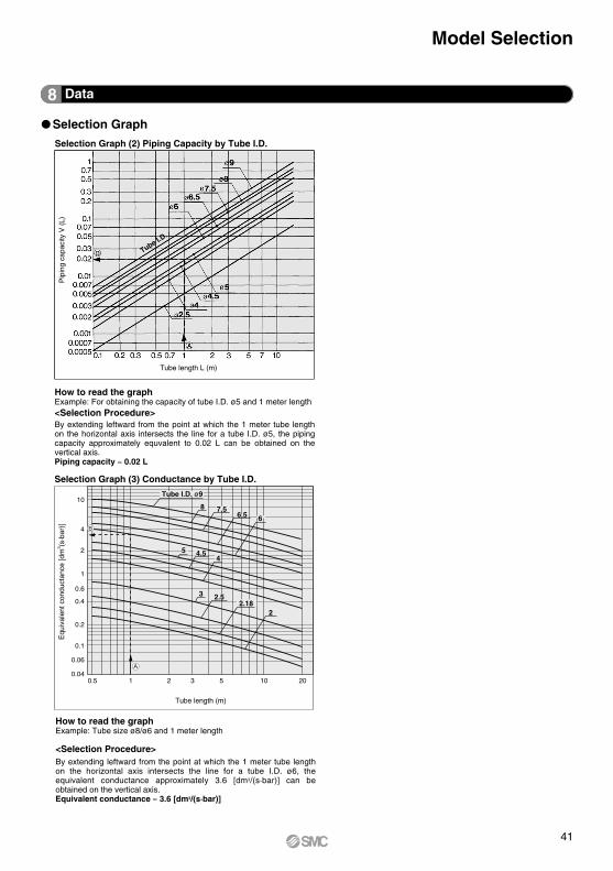
10
4
2
1
0.6
0.4
0.2
0.1
0.5 1 5 10 202 3
0.06
0.04
8
5
3
4.54
7.56.5
2.52.18
6
2
A
B
Data8
Pip
ing
capa
city
V (
L)
Tube I.D.
Tube length L (m)
How to read the graphExample: For obtaining the capacity of tube I.D. ø5 and 1 meter length <Selection Procedure>By extending leftward from the point at which the 1 meter tube length on the horizontal axis intersects the line for a tube I.D. ø5, the piping capacity approximately equvalent to 0.02 L can be obtained on the vertical axis.Piping capacity ≈ 0.02 L
Selection Graph (3) Conductance by Tube I.D.
How to read the graphExample: Tube size ø8/ø6 and 1 meter length
<Selection Procedure>By extending leftward from the point at which the 1 meter tube length on the horizontal axis intersects the line for a tube I.D. ø6, the equivalent conductance approximately 3.6 [dm3/(s·bar)] can be obtained on the vertical axis.Equivalent conductance ≈ 3.6 [dm3/(s·bar)]
Selection GraphSelection Graph (2) Piping Capacity by Tube I.D.
Tube I.D. ø9
Equ
ival
ent c
ondu
ctan
ce [d
m3 (s
·bar
)]
Tube length (m)
Model Selection
41

Glossary of Terms
(Max.) suction flow rate
Maximum vacuum pressure
Air consumption
Standard supply pressure
Exhaust characteristics
Flow rate characteristics
Vacuum pressure switch
(Air) supply valve
(Vacuum) release valve
Flow adjustment valve
Pilot pressure
External release
Vacuum port
Exhaust port
Supply port
Back pressure
Leakage
Response time
Average suction flow rate
Conductive pad
Vacuum pressure
Ejector
Air suction filter
Terms Description
Volume of air taken in by the ejector. The maximum value is the volume of air taken in without having anything connected to the vacuum port.
The maximum value of the vacuum pressure generated by the ejector
The compressed volume of air consumed by the ejector
The optimal supply pressure for operating the ejector
The relationship between the vacuum pressure and the suction flow rate when the supply pressure to the ejector has been changed.
The relationship between the vacuum pressure and the suction flow rate with the standard supply pressure supplied to the ejector.
Pressure switch for verifying the adsorption of a workpiece
Valve for supplying compressed air to the ejector
Valve for supplying positive pressure or air for breaking the vacuum state of the adsorption pad
Valve for adjusting the volume of air for breaking the vacuum
Pressure for operating the ejector valve
The action of breaking the vacuum using externally supplied air instead of using the ejector unit
Port for generating vacuum
Port for exhausting air consumed by the ejector, and air taken in from the vacuum port.
Port for supplying air to the ejector
Pressure inside the exhaust port
The entry of air into the vacuum passage, such as from an area between a workpiece and a pad, or between a fitting and a tube. The vacuum pressure decreases when leakage occurs.
The time from the application of the rated voltage to the supply valve or release valve,until V port pressure reaches the specified pressure.
The suction flow rate by the ejector or pump for calculating the response speed. It is 1/2 to 1/3 of the maximum suction flow rate.
A low electrical resistance pad for electrostatic prevention measure
Any pressure below the atmospheric pressure. When the atmospheric pressure is used as a reference, the pressure is presented by –kPa (G), and when the absolute pressure is used as a reference, the pressure is represented by kPa (abs).When referencing a piece of vacuum equipment such as an ejector, the pressure is generally represented by –kPa.
A unit for generating vacuum by discharging the compressed air from a nozzle at a high speed, based on the phenomenon in which the pressure is reduced when the air around the nozzle is sucked.
Vacuum filter provided in the vacuum passage for preventing the dust intrusion into the ejector, vacuum pump, or peripheral equipment
Model Selection
42
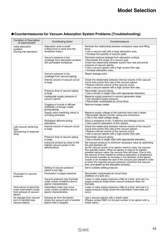
Condition & Descriptionof improvement Contributing factor Countermeasure
Initial adsorption problem(During trial operation)
Adsorption area is small.(Lifting force is lower than the workpiece mass.)
Recheck the relationship between workpiece mass and lifting force.• Use a vacuum pad with a large adsorption area.• Increase the quantity of vacuum pads.
Vacuum pressure is low.(Leakage from adsorption surface)(Air permeable workpiece)
Eliminate (reduce) leakage from adsorption surface. • Reconsider the shape of a vacuum pad.Check the relationship between suction flow rate and arrival pressure of vacuum ejector.• Use a vacuum ejector with a high suction flow rate.• Increase adsorption area.
Vacuum pressure is low.(Leakage from vacuum piping)
Repair leakage point.
Internal volume of vacuum circuit is large.
Check the relationship between internal volume of the vacuum circuit and suction flow rate of the vacuum ejector.• Reduce internal volume of the vacuum circuit.• Use a vacuum ejector with a high suction flow rate.
Pressure drop of vacuum piping is large.
Reconsider vacuum piping.• Use a shorter or larger tube (with appropriate diameter).
Inadequate supply pressure of vacuum ejector
Measure supply pressure in vacuum generation state.• Use standard supply pressure.• Reconsider compressed air circuit (line).
Clogging of nozzle or diffuser(Infiltration of foreign matter during piping)
Remove foreign matter.
Supply valve (switching valve) is not being activated.
Measure supply voltage at the solenoid valve with a tester.• Reconsider electric circuits, wiring and connectors.• Use in the rated voltage range.
Workpiece deforms during adsorption.
Since a workpiece is thin, it deforms and leakage occurs.• Use a pad for adsorption of thin objects.
Late vacuum achieving time(Shortening of response time)
Internal volume of vacuum circuit is large.
Check the relationship between internal volume of the vacuum circuit and suction flow rate of the vacuum ejector.• Reduce internal volume of the vacuum circuit.• Use a vacuum ejector with a high suction flow rate.
Pressure drop of vacuum piping is large.
Reconsider vacuum piping.• Use a shorter or larger tube (with appropriate diameter).
Using the product as close to the highest vacuum power in the specifications.
Set vacuum pressure to minimum necessary value by optimizing the pad diameter etc. As the vacuum power of an ejector (venturi) rises, the vacuum flow actually lowers. When an ejector is used at its highest possible vacuum value, the vacuum flow will lower. Due to this, the amount of time needed to achieve adsorption is lengthened.One should consider an increase in the diameter of the ejector nozzle or an increase the size of the vacuum pad utilized in order to lower the required vacuum pressure, maximum the vacuum flow, and speed up the adsorption process.
Setting of vacuum pressure switch is too high.
Set to suitable setting pressure.
Fluctuation in vacuum pressure
Fluctuation in supply pressure Reconsider compressed air circuit (line).(Addition of a tank etc.)
Vacuum pressure may fluctuate under certain conditions due to ejector characteristics.
Lower or raise supply pressure a little at a time, and use in a supply pressure range where vacuum pressure does not fluctuate.
Occurrence of abnormal noise (intermittent noise) from exhaust of vacuum ejector
Intermittent noise may occur under certain conditions due to ejector characteristics.
Lower or raise supply pressure a little at a time, and use in a supply pressure range where the intermittent noise does not occur.
Air leakage from vacuum port of manifold type vacuum ejector
Exhaust air from the ejector enters the vacuum port of another ejector that is stopped.
Use a vacuum ejector with a check valve.(Please contact SMC for the part number of an ejector with a check valve.)
P Countermeasures for Vacuum Adsorption System Problems (Troubleshooting)
Model Selection
43

Model Selection
Condition & Descriptionof improvement Contributing factor Countermeasure
Adsorption problem over time(Adsorption is normal during trial operation.)
Clogging of suction filter Replace filters.Improve installation environment.
Clogging of sound absorbing material
Replace sound absorbing materials.Add a filter to supply (compressed) air circuit.Install an additional suction filter.
Clogging of nozzle or diffuser Remove foreign matter.Add a filter to supply (compressed) air circuit.Install an additional suction filter.
Vacuum pad (rubber) deterioration, cracking, etc.
Replace vacuum pads.Check the compatibility of vacuum pad material and workpiece.
Workpiece is not released.
Inadequate release flow rate Open release flow adjustment needle.Vacuum pressure is high.Excessive force (adhesiveness of the rubber + vacuum pressure) is applied to the pad (rubber part).
Reduce the vacuum pressure.If inadequate lifting force causes a problem in transferring the workpieces, increase the number of pads.
Effects due to static electricity Use a conductive pad.Adhesiveness of the rubber increases due to the operating environment or wearing of the pad.• Adhesiveness of the rubber
material is high.• Adhesiveness increases due to
wearing of the vacuum pad (rubber).
Replace pads.Reconsider the pad material and check the compatibility of pad material and workpiece.Reconsider the pad form.(Changes to rib, groove, blast options)Reconsider the pad diameter and quantity of pads.
44

P Non-conformance Examples
Model Selection
Phenomenon Possible causes CountermeasureNo problem occurs during the test, but adsorption becomes unstable after starting operation.
• Setting of the vacuum switch is not appropriate. Supply pressure is unstable. Vacuum pressure does not reach the set pressure.
• There is leakage between the workpiece and the vacuum pad.
1) Set the pressure for the vacuum equipment (supply pressure, if using an ejector) to the necessary vacuum pressure during the adsorption of the workpieces. And set the set pressure for the vacuum switch to the necessary vacuum pressure for adsorption.
2) It is presumed that there was leakage during the test, but it was not serious enough to prevent adsorption. Reconsider the vacuum ejector and the shape, diameter, and material of the vacuum pad.Reconsider the vacuum pad.
Adsorption becomes unstable after replacing the pad.
• Initial setting conditions (vacuum pressure, vacuum switch setting, height of the pad) have changed. Settings have changed because the pad was worn out or had permanent setting due to the operating environment.
• When the pad was replaced, leakage was generated from the screw connection part, or the engagement between the pad and the adapter.
1) Reconsider the operating conditions including vacuum pressure, the set pressure of the vacuum switch, and the height of the pad.
2) Reconsider the engagement.
Identical pads are used to adsorb identical workpieces, but some of the pads cannot adsorb the workpieces.
• There is leakage between the workpiece and the vacuum pad.
• The supply circuit for the cylinder, the solenoid valve and the ejector is in the same pneumatic circuit system. The supply pressure decreases when they are used simultaneously. (Vacuum pressure does not increase.)
• There is leakage from the screw connection part or the engagement between the pad and the adapter.
1) Reconsider the pad diameter, shape, material, vacuum ejector (suction flow rate), etc.
2) Reconsider the pneumatic circuit.3) Reconsider the engagement.
Generation of sticking of bellows of the bellows pad and/or recovery delays.(It may occur at an early stage.)
When the vacuum pad (bellows type) reaches the end of its life, weakening of bent parts, wearing, or sticking of rubber parts occurs.
The operating conditions will determine the product life.Inspect it sufficiently and determine the replacement time.• Replace pads.• Reconsider the diameter, form, and material of vacuum pads.• Reconsider the quantity of vacuum pads.
Vacuum pressure is higher than necessary, so excessive force (adhesiveness of the rubber + vacuum pressure) is applied to the pad (rubber part).
Reduce the vacuum pressure. If inadequate lifting force causes a problem in transferring the workpieces due to the reduction of vacuum pressure, increase the number of pads.
Load is applied to the bellows due to the following operations, leading to sticking of rubber parts or reduction of the pad recovery performance.• Pushing exceeding pad displacement
(operating range), external load.• Workpiece holding/waitingWaiting 10 seconds or more while the workpiece is being held
* Even when under 10 seconds, pads sticking or a recovery delay issues may occur earlier depending on the operating environment and operating method.
Longer workpiece holding times lead to longer recovery times and a shorter life.
Reduce the load applied to the pad.• Review the equipment so that an external load
exceeding the pad displacement (operating range) is not applied.
• Avoid workpiece holding and waiting.The operating conditions will determine the product life. Inspect it and determine the replacement time.
The product life is shortened after replacement of the product (pad, buffer, etc.).
• The settings of the product changed.• Tube had been pulled.
Unbalanced load in clockwise direction increased.• The transfer speed increased.• The workpiece to be transferred was changed.
(Shape, center of gravity, weight, etc.)• The mounting orientation was at an angle.• The operating environment changed.• The buffer (mounting nut) was not
tightened with the appropriate torque.
If the problem (cannot adsorb) does not occur when starting operation, the product may reach the end of its life due to the customer's specification conditions.Reconsider the piping and operation (specifications).The selected model may not be appropriate for the current workpiece to be transferred or the specifications.Select the product model again by reconsidering the pad shape, diameter, quantity, and suction balance.
Pad comes out from the adapter during operation.Cracks are generated on the pad.
Load is applied to the pad (rubber part) due to the following factors.• Inadequate lifting force• Incorrect suction balance• Loads due to transfer acceleration are not
considered when selecting the product model.
The selected model may not be appropriate for the current workpiece to be transferred or the specifications.Select the product model again by reconsidering the pad shape, diameter, quantity, and suction balance.
45

Model Selection
Phenomenon Possible causes CountermeasureCracks are generated on the rubber (NBR, conduc-tive NBR).
• The product is operated in an ozone envi-ronment.
• An ionizer is used.* This phenomenon occurs earlier if
pushing or the high vacuum pressure is used.
Reconsider the operating environment.Reconsider the materials to be used.
Even when a mark-free pad is used, the pad end wears out quickly. (Suction marks are generated.)
If the pad adsorbs a highly clean work-piece, slippage is minimized, and a load (impact) is applied to the pad end.
Use the following products.• Stuck fluororesin pad• Clean attachment
Even when a mark-free pad is used, suction marks are generated.
• Incorrect application(The mark was generated due to a deformation.)
• Contamination (insufficient cleaning) on the pad when installing the equipment, dust in the operating environment etc.
Check the mark generated on the workpiece.1) Mark due to deformed (lined) workpiece
Reconsider the pad diameter, form, material, vacuum ejector (suction flow rate), etc.
2) Mark due to worn rubberReconsider the pad diameter, form, material, vacuum ejector (suction flow rate), etc.
3) Mark generated by moving componentsIf the suction mark disappears or becomes smaller after wiping with cloth or waste cloth (without using solu-tions), clean the pad as it may have been contaminated.Refer to "Cleaning method (Mark-free NBR pad)" on page 559 of this catalog.
46

When mounted with the nut, sometimes the buffer operation is not smooth, or the buffer does not slide.[Possible causes]• The tightening torque of the nut for mounting the buffer is too high.• Particles stuck to the sliding surface, or it is scratched.• Lateral load applied to the piston rod, causing eccentric wearing.
[Remedy]Tighten the nut to the recommended tightening torque.The nut may become loose depending on the operating conditions and environment. Be sure to perform regular maintenance.
How to Replace the Pad
Remove bolts with a hex. key wrench from the pad underside. Tighten new pad with the bolts ensuring there is no gap between the adapter plate and the pad.
Gap
Adapter plateAdapter plate
Mark
Pad
Hexagon socket head cap screw
Model Selection
ZP3
Product part no.Product specifications
Pad diameter Mounting thread sizeNut tightening torque
ZP3-∗(015 to 035) U∗
ZP3-∗(04 to 16) UM,B∗ZP3-∗(10 to 16) UM,B∗
M6 x 0.75M8 x 0.75
M8 x 0.75
ø1.5 to ø3.5
ø4 to ø16 2.0 to 2.5 N·m
2.0 to 2.5 N·m1.5 to 1.8 N·m
ZP/ZP2
Product part no.Product specifications
Pad diameter Mounting thread sizeNut tightening torque
ZP (02 to 08) U, BZP (10 to 16) UT, CZP (2004 to 4010) U
M8 x 1
M10 x 1
M14 x 1
ø2 to ø162004 to 4010
ø10 to ø32
ø20 to ø50
1.5 to 2.0 N·m
2.5 to 3.5 N·m
6.5 to 7.5 N·m
Heavy-duty Pad
Product part no.Product specifications
Pad diameter Mounting thread size Buffer body materialNut tightening torque
ZP (40/50) HZP (40/50) HB M18 x 1.5
M18 x 1.5
M22 x 1.5
Aluminum alloyBrassSteel
Aluminum alloyBrassSteel
Aluminum alloyBrassSteel
9.5 to 10.5 N·m28 to 32 N·m48 to 52 N·m
9.5 to 10.5 N·m28 to 32 N·m48 to 52 N·m
9.5 to 10.5 N·m45 to 50 N·m75 to 80 N·m
ø40, ø50
ø63, ø80
ø100, ø125
Heavy-duty Ball Joint Pad
Product part no.Product specifications
Pad diameter Mounting thread size Buffer body materialBrassSteelBrassSteelBrassSteel
Nut tightening torque
ZP2-F (40/50) HZP2-F (40/50) HB M18 x 1.5
M22 x 1.5
M22 x 1.5
ø40, ø50
ø63, ø80
ø100, ø125
28 to 32 N·m48 to 52 N·m45 to 50 N·m75 to 80 N·m45 to 50 N·m75 to 80 N·m
ZP (10 to 32) U, C, B, DZP (10 to 16) FZP (40, 50) U, C, B, DZP (20 to 50) F
ZP (63/80) HZP (63/80) HB
ZP (100/125) HZP (100/125) HB
ZP2-F (63/80) HZP2-F (63/80) HBZP2-F (100/125) HZP2-F (100/125) HB
JJBJF
JJBJF
JJBJF
JBJFJBJFJBJF
47
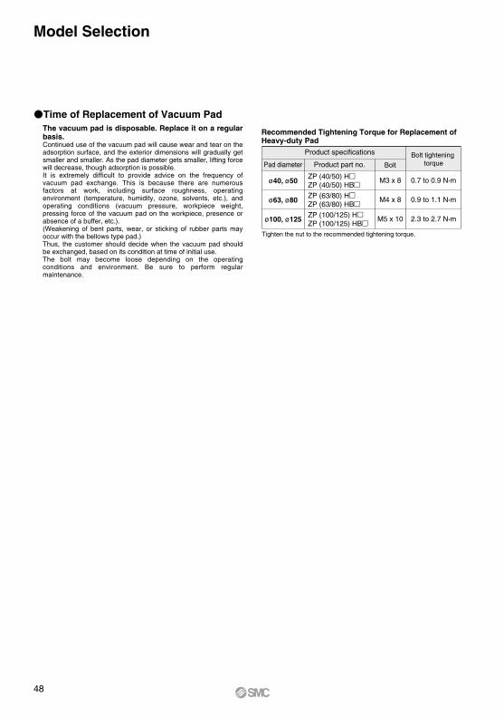
Time of Replacement of Vacuum PadThe vacuum pad is disposable. Replace it on a regular basis.Continued use of the vacuum pad will cause wear and tear on the adsorption surface, and the exterior dimensions will gradually get smaller and smaller. As the pad diameter gets smaller, lifting force will decrease, though adsorption is possible.It is extremely difficult to provide advice on the frequency of vacuum pad exchange. This is because there are numerous factors at work, including surface roughness, operating environment (temperature, humidity, ozone, solvents, etc.), and operating conditions (vacuum pressure, workpiece weight, pressing force of the vacuum pad on the workpiece, presence or absence of a buffer, etc.).(Weakening of bent parts, wear, or sticking of rubber parts may occur with the bellows type pad.)Thus, the customer should decide when the vacuum pad should be exchanged, based on its condition at time of initial use.The bolt may become loose depending on the operating conditions and environment. Be sure to perform regular maintenance.
Product specifications
Pad diameter Product part no. Bolt
Bolt tightening torque
ø40, ø50
ø63, ø80
ø100, ø125ZP (100/125) HZP (100/125) HB
M3 x 8
M4 x 8
M5 x 10
0.7 to 0.9 N·m
0.9 to 1.1 N·m
2.3 to 2.7 N·m
Tighten the nut to the recommended tightening torque.
ZP (40/50) HZP (40/50) HBZP (63/80) HZP (63/80) HB
Recommended Tightening Torque for Replacement of Heavy-duty Pad
Model Selection
48