vaisala calibration book -
TRANSCRIPT
CALIBRATION BOOK
DOC 213538
PUBLISHED BY
Vaisala Oyj
P.O. Box 26
FIN-00421 Helsinki
Finland
Phone (int.):
Fax:
(+358 9) 894 91
(+358 9) 8949 2227
Visit our Internet pages at http://www.vaisala.com/
© Vaisala 2006
No part of this book may be reproduced in any form or by any means, elec-tronic or mechanical (including photocopying), nor may its contents be communicated to a third party without prior written permission of the copyright holder.
The contents are subject to change without prior notice.
Please observe that this book does not create any legally binding obliga-tions for Vaisala towards the custormer or end user. All legally binding commitments and agreements are included exclusively in the applicable supply contract or Conditions of Sale.
PREFACEWe at Vaisala have worked many years manufacturing and calibrating measurement instruments. We have gained lots of calibration experi-ence, and working with our clients has revealed a need to increase common knowledge of what calibration is all about.
We put this book together to share some of our knowledge and some commonly known basics. We hope our readers find these pages use-ful.
Please feel free to send comments, questions and improvement sug-gestions to [email protected]
April 2006
Calibration book project team
Janne Kivilaakso
Antero Pitkäkoski
Jori Valli
Mike Johnson
Nobuo Inamoto
Arja Aukia
Masaki Saito
CONTENTSSCOPE.......................................................................... 1INTRODUCTION........................................................... 2
1.CALIBRATION REQUIREMENTS............................. 91.1.Quality management standards ........................ 91.2.Traceability ........................................................ 101.3.Calibration documentation .............................. 11
Validity of calibration .....................................................................12
2.METROLOGY AND CALIBRATION SERVICES..... 142.1.International cooperation................................. 15
Legal metrology..............................................................................15Metrology ........................................................................................17Accreditation ..................................................................................18
2.2.National measurement standard laboratories 192.3.Commercial calibration services..................... 20
Accredited laboratories .................................................................20Non-accredited calibration services and laboratories................21
2.4.In-house calibration.......................................... 21Organization and management.....................................................21Technical documentation ..............................................................22Choosing reference equipment ....................................................22
3.CALIBRATION ACTIVITIES.................................... 23What should we do with the calibration results?........................25
3.1.Choosing calibration method .......................... 26When calibration is needed...........................................................26Laboratory and field calibration....................................................26Field spot checking........................................................................30
3.2.Determining the calibration interval................ 31Lengthening the calibration interval.............................................32Shortening the calibration interval ...............................................32
3.3.Choosing calibration points ............................ 333.4.Calibration methods by the user ..................... 33
Temperature equilibrium ...............................................................35Stabilization and sampling ............................................................35Uncertainty estimation...................................................................36Presenting the results....................................................................37
4.CALIBRATION IN PRACTICE................................. 394.1.Humidity calibration ......................................... 39
Choosing reference equipment ....................................................39Relative humidity calibration ........................................................46Dewpoint temperature calibration ................................................53
4.2.Temperature calibration ................................... 58ITS-90 Temperature Scale .............................................................59Choosing reference equipment ....................................................60Temperature calibration methods ................................................68
4.3.Pressure calibration ......................................... 71Choosing reference equipment ....................................................72Pressure calibration methods.......................................................76
5.VAISALA CALIBRATION SERVICES..................... 79
APPENDIX A: TERMINOLOGY.................................. 83APPENDIX B: ABBREVIATIONS............................... 95APPENDIX C: UNCERTAINTY CALCULATION........ 97REFERENCES.......................................................... 111
SCOPE
In today's knowledge driven world we want to understand and control things based on real data. Performing measurements with measurement equipment is one part of this quest in various fields. However, having measurement equipment in place is only part of the picture. One should always make sure that the data produced by the measurement equipment is reliable and accu-rate. Naturally the measurement equipment must be fit for the purpose and used in a correct way.
This book was written to help benefit the readers as much as possible in the measurements they perform. This book aims to help readers and their organi-zations determine the most appropriate activities that ensure their measure-ment quality requirements. We hope this book provides frameworks to help the readers think in relation to one's own activities.
This book serves as a generic introduction to calibration. We discuss the rational behind calibration, and the factors that effect the need to calibrate. It also provides some specific information on calibration of relative humidity, dewpoint temperature, temperature and barometric pressure.
1 SCOPE
CALIBRATION BOOK
INTRODUCTION
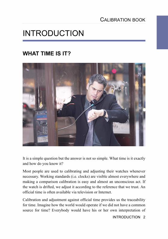
WHAT TIME IS IT?
It is a simple question but the answer is not so simple. What time is it exactly and how do you know it?
Most people are used to calibrating and adjusting their watches whenever necessary. Working standards (i.e. clocks) are visible almost everywhere and making a comparison calibration is easy and almost an unconscious act. If the watch is drifted, we adjust it according to the reference that we trust. An official time is often available via television or Internet.
Calibration and adjustment against official time provides us the traceability for time. Imagine how the world would operate if we did not have a common source for time? Everybody would have his or her own interpretation of
INTRODUCTION 2
time. Trains and planes would leave by the definition of time the operating companies use, and passengers would either catch or miss their carriage depending on time on their wristwatches.
So perhaps calibration is not such a difficult topic. We actually do it in our private and working life all the time, and it´s important, isn't it?
The International System of Units (SI)From global perspective all measurements are based on the globally agreed International System of Units (SI). This ensures that we use the same quanti-ties and that measurements performed with various types of equipment in various locations are comparable. The further we are from the International System of Units (SI) the higher uncertainty we have in the measurement in terms of absolute accuracy.
To learn more visit the website of International Bureau of Weights and Measures (BIPM).
http://www.bipm.org/en/si/
Why the measurements are neededThe key factor about measurement, is to understand when it is important to truly know the reliability of measurement results.
Things are measured for the information the measurement provides, not for the sake of measuring itself.
The value of information determines the requirements for appropriate metro-logical confirmation processes. These requirements influence the choice of the measurement equipment and calibration practices.
How then do we define the value of information obtained? It comes from why you need the information the measurement provides. The following are some examples.
3 INTRODUCTION
CALIBRATION BOOK
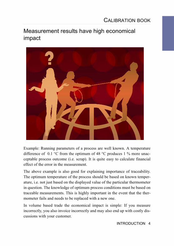
Measurement results have high economical impact
Example: Running parameters of a process are well known. A temperature difference of 0.1 °C from the optimum of 48 °C produces 1 % more unac-ceptable process outcome (i.e. scrap). It is quite easy to calculate financial effect of the error in the measurement.
The above example is also good for explaining importance of traceability. The optimum temperature of the process should be based on known temper-ature, i.e. not just based on the displayed value of the particular thermometer in question. The knowledge of optimum process conditions must be based on traceable measurements. This is highly important in the event that the ther-mometer fails and needs to be replaced with a new one.
In volume based trade the economical impact is simple: If you measure incorrectly, you also invoice incorrectly and may also end up with costly dis-cussions with your customer.
INTRODUCTION 4
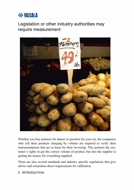
Legislation or other industry authorities may require measurement
Whether you buy potatoes for dinner or gasoline for your car, the companies who sell their products charging by volume are required to verify their instrumentations that act as basis for their invoicing. This protects the cus-tomer´s rights to get the correct volume of product, but also the supplier is getting the money for everything supplied.
There are also several standards and industry specific regulations that give advice and sometimes direct requirements for calibration.
5 INTRODUCTION
CALIBRATION BOOK
Measurement results are connected to health, safety or environmental risksMeasurements may be in place to protect employees for occupational health hazards. There are various quantities measured such a toxic concentrations for different gases. For example, working conditions must be kept under cer-tain limits. Reliable measurements in this area are vitally important and no compromises should be made.
An example of a health risk is the manufacturing of food. The product must be sterilized in certain temperatures to kill bacteria. The measurements to prove this must be reliable.
Many health, safety, and environmental risk-related measurements are also required by legislation or industry standards.
Measurement results are used to obtain research resultsResearchers are working on creating new knowledge. In the scientific world one of the key factors is to get the desired results, but to also understand why, and how the results are accomplished. In many fields of research the ambient and process conditions, as well as end results are measured and doc-umented. After series of tests and trials, lots of data are analyzed to under-stand various phenomena and relations between them. Since reproducibility of tests, or whatever is performed, may not be achieved it is quite clear that false assumptions (such as faulty measurement results which are thought to be correct) can jeopardize a whole research. In research calibration plays a vital role before, during and after tests.
Distributed manufacturingIf you produce products in multiple locations and find optimal setups for the highest possible yield and quality yet, have a hard time doing the same in some other locations or other machines. Maybe the measurement results are not the same?
INTRODUCTION 6
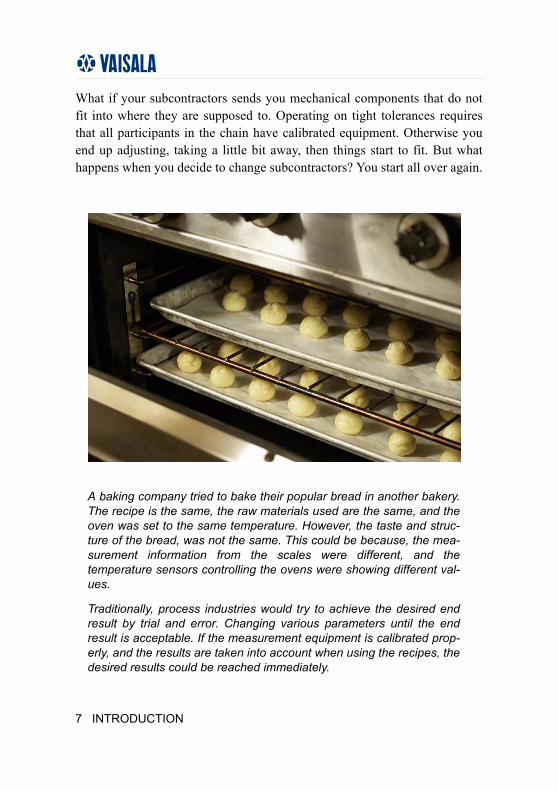
What if your subcontractors sends you mechanical components that do not fit into where they are supposed to. Operating on tight tolerances requires that all participants in the chain have calibrated equipment. Otherwise you end up adjusting, taking a little bit away, then things start to fit. But what happens when you decide to change subcontractors? You start all over again.
A baking company tried to bake their popular bread in another bakery. The recipe is the same, the raw materials used are the same, and the oven was set to the same temperature. However, the taste and struc-ture of the bread, was not the same. This could be because, the mea-surement information from the scales were different, and the temperature sensors controlling the ovens were showing different val-ues.
Traditionally, process industries would try to achieve the desired end result by trial and error. Changing various parameters until the end result is acceptable. If the measurement equipment is calibrated prop-erly, and the results are taken into account when using the recipes, the desired results could be reached immediately.
7 INTRODUCTION
CALIBRATION BOOK
Calibration practices in a nutshellTo put an effective calibration system in place you have to:
• Understand the value of information the measurements provide.
• Identify your measurement equipment.
• Set up appropriate processes for calibration of your measurement equip-ment.
INTRODUCTION 8
1.CALIBRATION REQUIREMENTS
Requirements for calibration systems are usually set locally by legislation and regulations, customer expectations, or own internal needs.In case the requirements are legally set the calibration system must be designed to fulfill these requirements.In case the customer expectations or own internal needs are to be fulfilled there are several Quality Management Standards (QMS) from which to choose from. A few of them are: ISO 9000:2000, QS 9000, ISO/TS 16949:2002 and Good Laboratory Practice (GLP). These all state the mini-mum requirements and guidance for the maintenance of measurement equip-ment.Under the selected QMS the measurement equipment maintenance system and actual calibration system is built.In case more effective measurement equipment maintenance system is needed the ISO 10012, ANSI/NCSL Z540 or ISO/IEC 17025 is selected.
1.1.QUALITY MANAGEMENT STANDARDS
Quality Management Standards like ISO 9000:2000, QS 9000, ISO/TS 16949:2002 and Good Laboratory Practice (GLP) all state the minimum requirements for the maintenance of measure-ment equipment.
ISO10012 Measurement Management Systems - Requirements for Measurement Processes and Measuring Equipment is spe-cially designed for measurement equipment maintenance.ISO/IEC 17025 General Requirements for the Competence of Testing and Calibration Laboratories, is a laboratory accreditation standard used globally.
9 CALIBRATION REQUIREMENTS
CALIBRATION BOOK
ANSI/NCSL Z540 General Requirements for Calibration Labora-tories and Measuring and Test Equipment, is a laboratory accredi-tation standard used alternatively in USA.MIL-STD-45662A Calibration Systems Requirements, has been cancelled on February 27, 1995 and ISO 10012 or ANSI/NCSL Z540 is preferred if these requirements apply.
1.2.TRACEABILITY
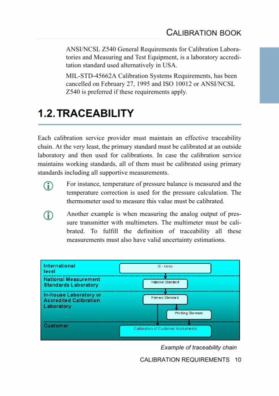
Each calibration service provider must maintain an effective traceability chain. At the very least, the primary standard must be calibrated at an outside laboratory and then used for calibrations. In case the calibration service maintains working standards, all of them must be calibrated using primary standards including all supportive measurements.
For instance, temperature of pressure balance is measured and the temperature correction is used for the pressure calculation. The thermometer used to measure this value must be calibrated.
Another example is when measuring the analog output of pres-sure transmitter with multimeters. The multimeter must be cali-brated. To fulfill the definition of traceability all these measurements must also have valid uncertainty estimations.
Example of traceability chain
CALIBRATION REQUIREMENTS 10
1.3.CALIBRATION DOCUMENTATION
In all of the QMS's the management of measurement equipment is based on regular calibrations at predefined intervals with a documentation system by which this can be proven. This documentation system should contain as min-imum:
1. Organization, management•Responsibilities, job descriptions, training plans and training records
•Management review plan and records of the meetings.
2. Register of measurement equipment•Each measurement equipment should be identifiable which means some kind of numbering system attached to the equipment.
•Register should contain the history of the equipment and the time for the next calibration.
3. Archives containing issued calibration certificates. The certificates should be stored for the time documented in the QMS.
4. Procedures for faulty measurement equipment5. Procedures for receiving customer feedback, solving complaints, correc-
tive and preventive actions6. Quality audit plan and records from previous audits, findings and correc-
tive actions.
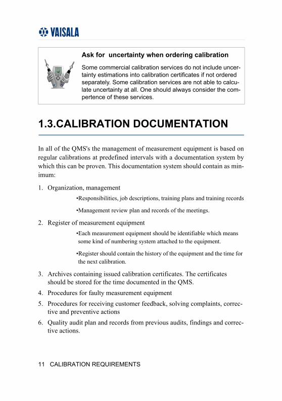
Ask for uncertainty when ordering calibration
Some commercial calibration services do not include uncer-tainty estimations into calibration certificates if not ordered separately. Some calibration services are not able to calcu-late uncertainty at all. One should always consider the com-pertence of these services.
11 CALIBRATION REQUIREMENTS
CALIBRATION BOOK
In addition to those listed in the previous chapter, the calibration service should also document:
1. Equipment, facilities, conditions, verification and maintenance2. Traceability3. Uncertainty calculations4. Calibration instructions5. Stability of the reference equipment6. Comparison calibration plan and results.
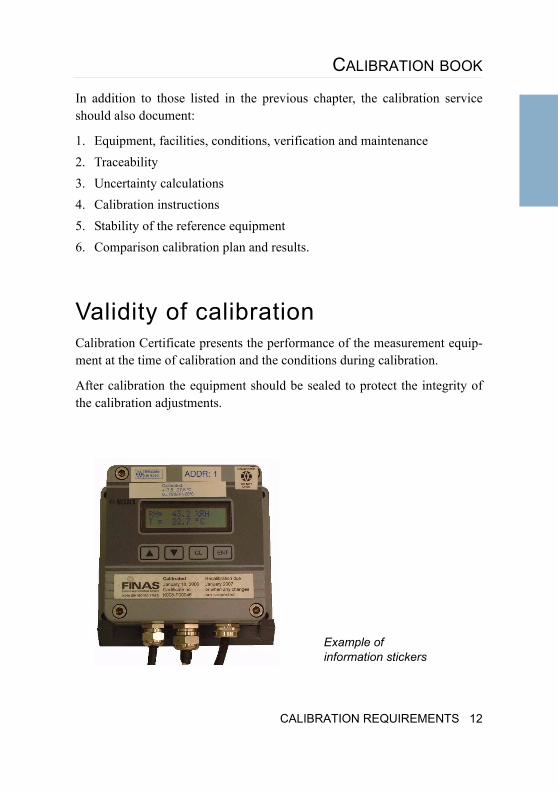
Validity of calibrationCalibration Certificate presents the performance of the measurement equip-ment at the time of calibration and the conditions during calibration.
After calibration the equipment should be sealed to protect the integrity of the calibration adjustments.
Example of information stickers
CALIBRATION REQUIREMENTS 12
Recalibration intervalThe procedure for determining the recalibration interval should be defined in QMS. The recalibration interval should be recorded into the measurement equipment maintenance system for each measurement equipment.
Each measurement equipment should have a sticker that states the next cali-bration date. The calibration laboratory can provide this if agreed with cus-tomer.
There should be procedures in the QMS on how to handle and remove the measurement equipment from service, when the calibration is overdue, cali-bration sticker or calibration seal are broken or missing.
There should be procedures in the QMS how the use of the most demanding measurements are secured.
Examples:
Continuously using two independent measurement equipment and comparing the readings
Periodical comparison of a process unit with a working standard (Spot checking).
13 CALIBRATION REQUIREMENTS
CALIBRATION BOOK
2.METROLOGY AND CALIBRATION SERVICES
Traditionally, metrology was organized by the users of specific areas. The measurements related to trade and safety have been under legal metrology and regulated by the local legislation.
The purpose of legal metrology has been to ensure correct measurement results in trade to protect customers.
Scientific metrology has been developed freely in research institutes when doing physical research in order to develop more accurate measurement methods and equipment.
Beside these two 'paths' there has always been metrology cooperation inside different organizations. As an example the World Meteorological Organiza-tion (WMO) has developed and standardized the measurement equipment and techniques related to meteorological observations.
The basis of modern metrology is set in Convention of the Metre, which is a diplomatic treaty which gives authority to the General Conference on Weights and Measures (CGPM), the International Committee for Weights and Measures (CIPM) and the International Bureau of Weights and Mea-sures (BIPM) to act in matters of world metrology, particularly concerning the demand for measurement standards of ever increasing accuracy, range, diversity, and the need to demonstrate equivalence between national mea-surement standards.
The backbone of metrology is the International System of Units (SI).
Metrology organizations are built to maintain and improve the International System of Units (SI) and provide accurate measurement and calibration ser-vices.
The International System of Units (SI) is maintained by BIPM (International Bureau of Weights and Measures) in France. The task of the BIPM is to
METROLOGY AND CALIBRATION SERVICES 14
ensure worldwide uniformity of measurements and their traceability to the International System of Units (SI).
National laboratories are representing the top metrology level maintaining and developing traceability and providing the highest accuracy calibrations.
Accredited and other calibration services are then providing the traceability to the users.
2.1.INTERNATIONAL COOPERATION
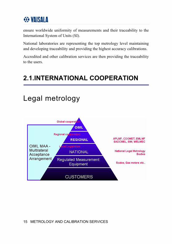
Legal metrology
15 METROLOGY AND CALIBRATION SERVICES
CALIBRATION BOOK
Legal metrology covers all the legislative, administrative and technical pro-cedures established by, or referenced by public authorities, and implemented on their behalf in order to specify and to ensure, in a regulatory or contrac-tual manner, the appropriate quality and credibility of measurements related to official controls, trade, health, safety and the environment.
The International Organization of Legal Metrology (OIML) is an intergov-ernmental treaty organization coordinating legal metrology.
The International Bureau of Legal Metrology (BIML) is the secretar-iat and headquarters of the OIML, ensuring both the day to day run-ning of activities and the planning of longer term actions.
OIML has developed a worldwide technical structure that provides its mem-bers with metrological guidelines for the elaboration of national and regional requirements concerning the manufacturer and use of measurement equip-ment for legal metrology applications.
Regionally, the legal metrology is coordinated by Asia-Pacific Legal Metrol-ogy Forum (APLMF), Euro-Asian Cooperation of National Metrological Institutions (COOMET), Euro-Mediterranean Legal Metrology Forum (EMLMF), European Cooperation in legal metrology (WELMEC), Sistema Interamericano de Metrologia (SIM), and Southern African Development Community (SADCMEL).
The National Legal Metrology Bodies implement the legal metrology.
METROLOGY AND CALIBRATION SERVICES 16
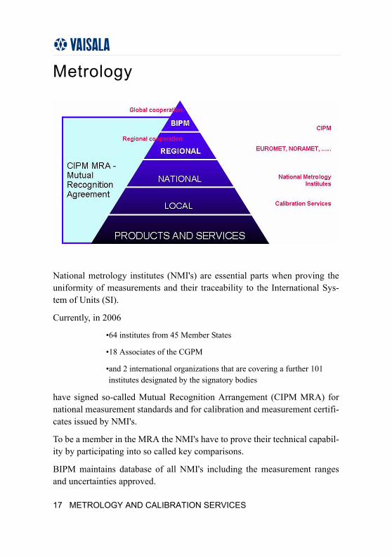
Metrology
National metrology institutes (NMI's) are essential parts when proving the uniformity of measurements and their traceability to the International Sys-tem of Units (SI).
Currently, in 2006
•64 institutes from 45 Member States
•18 Associates of the CGPM
•and 2 international organizations that are covering a further 101 institutes designated by the signatory bodies
have signed so-called Mutual Recognition Arrangement (CIPM MRA) for national measurement standards and for calibration and measurement certifi-cates issued by NMI's.
To be a member in the MRA the NMI's have to prove their technical capabil-ity by participating into so called key comparisons.
BIPM maintains database of all NMI's including the measurement ranges and uncertainties approved.
17 METROLOGY AND CALIBRATION SERVICES
CALIBRATION BOOK
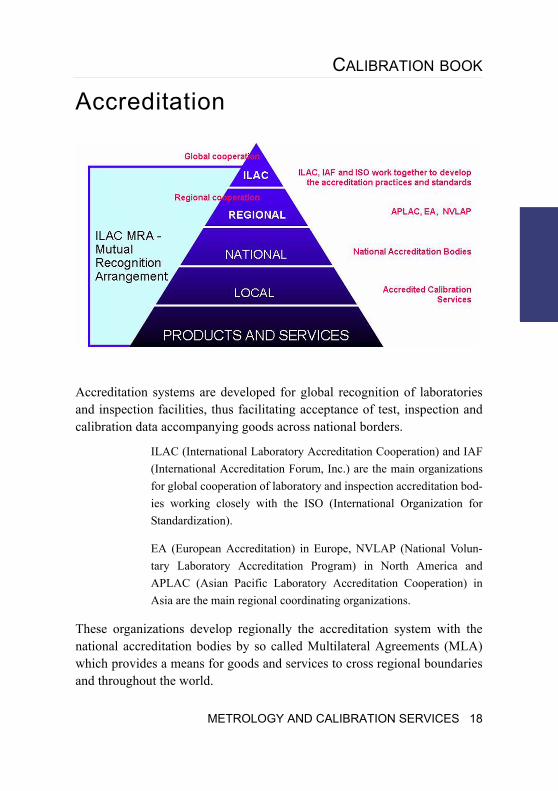
Accreditation
Accreditation systems are developed for global recognition of laboratories and inspection facilities, thus facilitating acceptance of test, inspection and calibration data accompanying goods across national borders.
ILAC (International Laboratory Accreditation Cooperation) and IAF (International Accreditation Forum, Inc.) are the main organizations for global cooperation of laboratory and inspection accreditation bod-ies working closely with the ISO (International Organization for Standardization).
EA (European Accreditation) in Europe, NVLAP (National Volun-tary Laboratory Accreditation Program) in North America and APLAC (Asian Pacific Laboratory Accreditation Cooperation) in Asia are the main regional coordinating organizations.
These organizations develop regionally the accreditation system with the national accreditation bodies by so called Multilateral Agreements (MLA) which provides a means for goods and services to cross regional boundaries and throughout the world.
METROLOGY AND CALIBRATION SERVICES 18
2.2.NATIONAL MEASUREMENT STANDARD LABORATORIES
National Measurement Standard Laboratories are usually situated under the NMI's or they may be contract laboratories. Usually National Measurement Standard Laboratories are responsible for providing and organizing calibra-tion services needed by local society.
The calibration services of the National Measurement Standard Laboratories may be limited to calibration of the highest grade primary standards.
What is the accreditation process
A test report, inspection report, or a certificate issued by an accredited body in one country is recognised as equivalent to a report or a certificate issued by an accredited body in any of the countries signatories to the MLA. Accreditation bodies recognise that they operate in an equivalent way and that they deliver equivalent accreditations, providing the same level of competence and confidence.
The MLA makes accreditation a "passport" which facili-tates access to international markets through co-opera-tion with ILAC (International Laboratory Accreditation Co-operation) and IAF (International Accreditation Forum).
19 METROLOGY AND CALIBRATION SERVICES
CALIBRATION BOOK
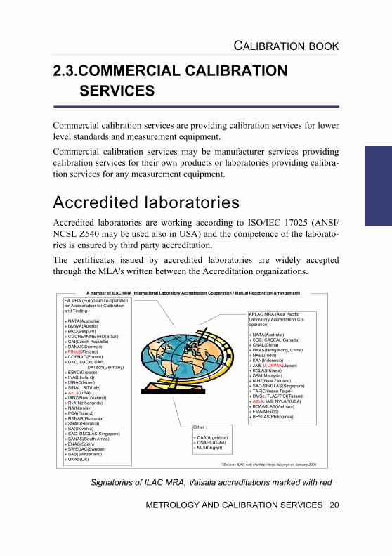
2.3.COMMERCIAL CALIBRATION SERVICES
Commercial calibration services are providing calibration services for lower level standards and measurement equipment. Commercial calibration services may be manufacturer services providing calibration services for their own products or laboratories providing calibra-tion services for any measurement equipment.
Accredited laboratoriesAccredited laboratories are working according to ISO/IEC 17025 (ANSI/NCSL Z540 may be used also in USA) and the competence of the laborato-ries is ensured by third party accreditation.The certificates issued by accredited laboratories are widely accepted through the MLA's written between the Accreditation organizations.
APLAC MRA (Asia Pacific Laboratory Accreditation Co-operation) :
+ NATA(Australia)+ SCC, CASEAL(Canada)+ CNAL(China)+ HKAS(Hong Kong, China)+ NABL(India)+ KAN(Indonesia)+ JAB, IA JAPAN(Japan)+ KOLAS(Korea)+ DSM(Malaysia)+ IANZ(New Zealand)+ SAC-SINGLAS(Singapore)+ TAF(Chinese Taipei)+ DMSc, TLAS/TISI(Tailand)+ A2LA, IAS, NVLAP(USA)+ BOA/VILAS(Vietnam)+ EMA(Mexico)+ BPSLAS(Philippines)
EA MRA (European co-operation for Accreditation for Calibration and Testing :
+ NATA(Australia)+ BMWA(Austria)+ BKO(Belgium)+ CGCRE/INMETRO(Brazil)+ CAI(Czech Republic)+ DANAK(Denmark)+ FINAS(Finland)+ COFRAC(France)+ DKD, DACH, DAP, DATech(Germany)+ ESYD(Greece)+ INAB(Ireland)+ ISRAC(Israel)+ SINAL, SIT(Italy)+ A2LA(USA)+ IANZ(New Zealand)+ RvA(Netherlands)+ NA(Norway)+ PCA(Poland)+ RENAR(Romania)+ SNAS(Slovakia)+ SA(Slovenia)+ SAC-SINGLAS(Singapore)+ SANAS(South Africa)+ ENAC(Spain)+ SWEDAC(Sweden)+ SAS(Switzerland)+ UKAS(UK)
Other :
+ OAA(Argentina)+ ONARC(Cuba)+ NLAB(Egypt)
A member of ILAC MRA (International Laboratory Accreditation Cooperation / Mutual Recognition Arrangement)
* Source : ILAC web site(http://www.ilac.org/) on January 2006
Signatories of ILAC MRA, Vaisala accreditations marked with red
METROLOGY AND CALIBRATION SERVICES 20
Non-accredited calibration services and laboratoriesNon accredited calibration services are the major service providers contain-ing most of the measurement equipment manufacturers calibration services and large amount of commercial calibration services.
Without accreditation the competence of these services is not proven and before use the competence should be confirmed by auditing the service.
2.4.IN-HOUSE CALIBRATION
Sometimes it is practical to maintain a in-house calibration system. This may be the case if the measurement equipment is difficult to transfer (calibration on site) or when the amount of calibrated equipment is high.
To set up the in-house calibration system suitable organization should be founded. The organization may contain just one person or whole department with management and calibration staff.
In any case the duties of personnel should be recorded and adequate training provided.
Organization and managementA simple in-house calibration function may be just one person nominated for the calibration tasks. In larger organizations the organization structure, man-agement, responsibilities, job descriptions, training plans and training records should be documented.
These documents should also contain:
• Procedures for faulty measurement equipment
21 METROLOGY AND CALIBRATION SERVICES
CALIBRATION BOOK
• Procedures for receiving customer feedback, solving complaints, correc-tive and preventive actions
• Quality audit plan and records of previous audits, findings, corrective and preventive actions
• Defined document retention times
• Comparison calibration plan and results of previous comparisons.
Technical documentationTechnical documentation should contain reference equipment, facilities, conditions, verification and maintenance of the reference equipment.
Technical documentation should also contain:
• Traceability
• Uncertainty calculations
• Calibration instructions
• Stability of the reference equipment.
Choosing reference equipmentThe selection of the reference equipment depends on the chosen calibration method and accuracy needed. Some considerations are as follows:
•Accuracy, the chosen reference must be accurate enough for the intended calibrations.
•Range, the measurement range of the chosen reference must cover the whole range needed.
•Calibration service, suitable calibration service must be available.
•Transportation, the reference should not be sensitive to be damaged during transportation.
•Usability, the reference should be suitable for the intended use and user friendly.
METROLOGY AND CALIBRATION SERVICES 22
3.CALIBRATION ACTIVITIES
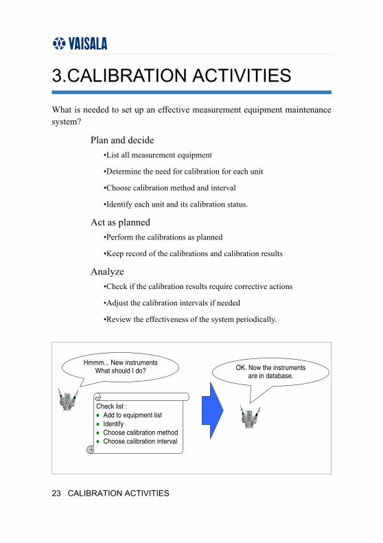
What is needed to set up an effective measurement equipment maintenance system?
Plan and decide•List all measurement equipment
•Determine the need for calibration for each unit
•Choose calibration method and interval
•Identify each unit and its calibration status.
Act as planned•Perform the calibrations as planned
•Keep record of the calibrations and calibration results
Analyze•Check if the calibration results require corrective actions
•Adjust the calibration intervals if needed
•Review the effectiveness of the system periodically.
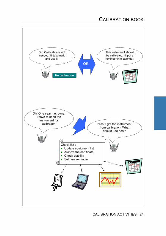
Hmmm... New instruments What should I do?
Check list : •••• Add to equipment list •••• Identify •••• Choose calibration method •••• Choose calibration interval
OK. Now the instruments are in database.
23 CALIBRATION ACTIVITIES
CALIBRATION BOOK
OK. Calibration is not needed. I'll just mark
and use it.
No calibration
This instrument should be calibrated. I'll put a reminder into calendar.
OR
Oh! One year has gone. I have to send the
instrument for calibration. Nice! I got the instrument
from calibration. What should I do now?
Check list : •••• Update equipment list •••• Archive the certificate •••• Check stability •••• Set new reminder
CALIBRATION ACTIVITIES 24
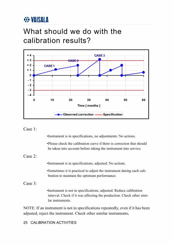
What should we do with the calibration results?
Case 1:•Instrument is in specifications, no adjustments: No actions.
•Please check the calibration curve if there is correction that should be taken into account before taking the instrument into service.
Case 2:•Instrument is in specifications, adjusted: No actions.
•Sometimes it is practical to adjust the instrument during each cali-bration to maintain the optimum performance.
Case 3:•Instrument is not in specifications, adjusted: Reduce calibration interval. Check if it was affecting the production. Check other simi-lar instruments.
NOTE: If an instrument is not in specifications repeatedly, even if it has been adjusted, reject the instrument. Check other similar instruments.
- 4- 3- 2- 1
0+ 1+ 2+ 3+ 4
0 10 20 30 40 50 60
Time [ months ]
Observed correction Specification
CASE 1CASE 2
CASE 3
25 CALIBRATION ACTIVITIES
CALIBRATION BOOK
3.1.CHOOSING CALIBRATION METHOD
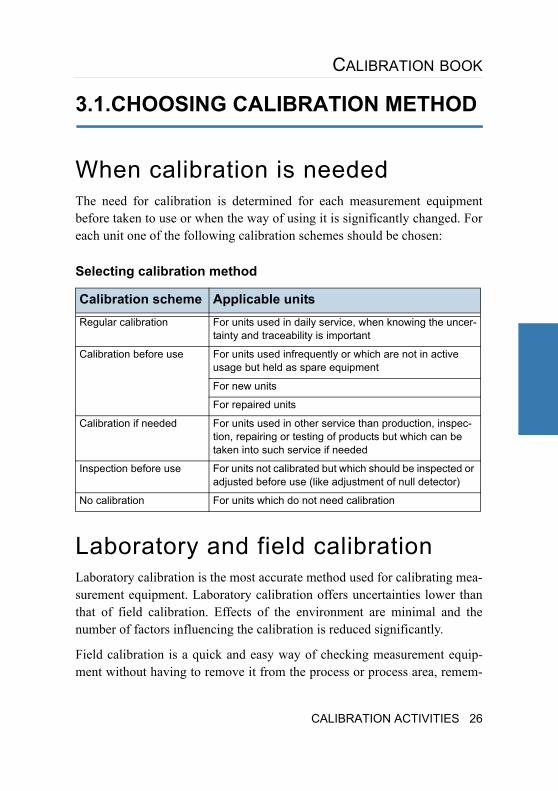
When calibration is neededThe need for calibration is determined for each measurement equipment before taken to use or when the way of using it is significantly changed. For each unit one of the following calibration schemes should be chosen:
Selecting calibration method
Laboratory and field calibrationLaboratory calibration is the most accurate method used for calibrating mea-surement equipment. Laboratory calibration offers uncertainties lower than that of field calibration. Effects of the environment are minimal and the number of factors influencing the calibration is reduced significantly.
Field calibration is a quick and easy way of checking measurement equip-ment without having to remove it from the process or process area, remem-
Calibration scheme Applicable units Regular calibration For units used in daily service, when knowing the uncer-
tainty and traceability is important
Calibration before use For units used infrequently or which are not in active usage but held as spare equipment
For new units
For repaired units
Calibration if needed For units used in other service than production, inspec-tion, repairing or testing of products but which can be taken into such service if needed
Inspection before use For units not calibrated but which should be inspected or adjusted before use (like adjustment of null detector)
No calibration For units which do not need calibration
CALIBRATION ACTIVITIES 26
bering that proper stabilization times are allowed for both the UUC and the working standard.
Users must decide which is the most optimal method for their approach and this section will outline some advantages and disadvantages of both.
Equipment required for field calibrationField calibration requires a working standard as a reference. This working standard could be a hand-held or some other equipment that would be used to calibrate the instrument installed in the process.
The working standard is only used for calibration and should not be used in any part of the monitoring operation of the process. Care should be taken when handling the working standard and proper storage is required to ensure its functionality.
A calibrator can also be used in the field to produce a multi-point calibration. Some calibrators are stand alone reference standards. This means that there is no need for a separate working standard.
Working standards are generally calibrated at a higher level laboratory.
27 CALIBRATION ACTIVITIES
CALIBRATION BOOK
Advantages of field one-point calibrationField calibration offers the user the ability to calibrate the instrument in place. Leaving the instrument installed into the process eliminates any down-time that would incur while removing and re-installing the instrument from the process.
Calibration is made at one-point against the working standard by placing the working standard as close to the UUC as possible. Stabilization time must be allowed to reach temperature equilibrium between the working standard and the UUC. Attention must be paid to the proximity of the working standard to the UUC, temperature gradients, air flow, pressure differences, and any other factors that could influence the calibration results.
One-point calibration is an effective way to maintain a sensor's performance for operating conditions that do not vary. Sensors that are constantly main-tained at one temperature, one humidity, one pressure and so on would be ideal cases for one-point calibration.
Disadvantages of field one-point calibrationThere are also disadvantages in field calibration that should be mentioned. Field calibrations with the instrument installed in the process limit the cali-bration curve to one point only. Many processes vary in conditions and the one-point calibration limits the curve over a small portion of the operating conditions.
ATTENTION:
Before inserting a hand-held meter or other working standard into a process, make sure that the operating conditions do not exceed its specifications.
CALIBRATION ACTIVITIES 28
Advantages of field multi-point calibrationUsing a working standard and generator or chamber, which is able to pro-duce various points enables the user to perform multi-point field calibration. The difference between one-point field calibration and multi-point field cali-bration is that the UUC must be removed1 from the process.
The time saved performing multi-point field calibration to that of laboratory calibration can be significant.
Disadvantages of field multi-point calibrationField calibration generally carries a higher calibration uncertainty than labo-ratory calibration.
Labor and traveling costs may be significantly higher than in laboratory cali-brations. In laboratory the reference equipment are usually constantly avail-able and several instruments may be calibrated simultaneously.
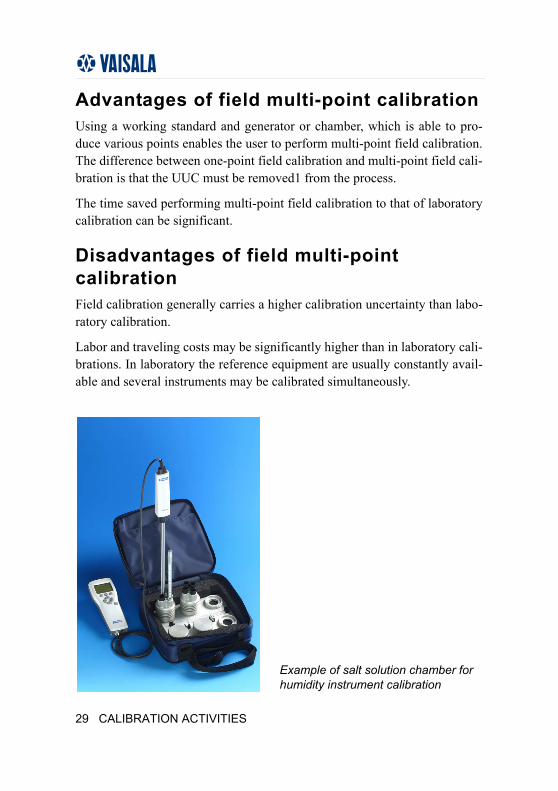
Example of salt solution chamber for humidity instrument calibration
29 CALIBRATION ACTIVITIES
CALIBRATION BOOK
Field spot checkingSpot checking is a quick and easy way to determine proper operation of a unit. Spot checking should not be confused with field calibration. They are very similar in the respect that a reference equipment is placed near the sen-sor that is being checked and the readings are compared to that of the installed instrument. In spot checking stabilization time is not as crucial as it is in field calibration, and therefore time used for the checking is much shorter.
Spot-checking can be viewed as a good addition to measurement equipment maintenance. As an example if a unit is calibrated annually in a laboratory, it could be subject to spot checking every 3 months.
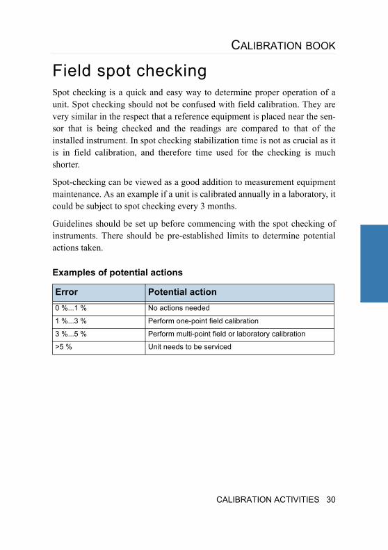
Guidelines should be set up before commencing with the spot checking of instruments. There should be pre-established limits to determine potential actions taken.
Examples of potential actions
Error Potential action0 %...1 % No actions needed
1 %...3 % Perform one-point field calibration
3 %...5 % Perform multi-point field or laboratory calibration
>5 % Unit needs to be serviced
CALIBRATION ACTIVITIES 30
3.2.DETERMINING THE CALIBRATION INTERVAL
The decision on the calibration interval must always be made by the user, however there are common practise guidelines available.
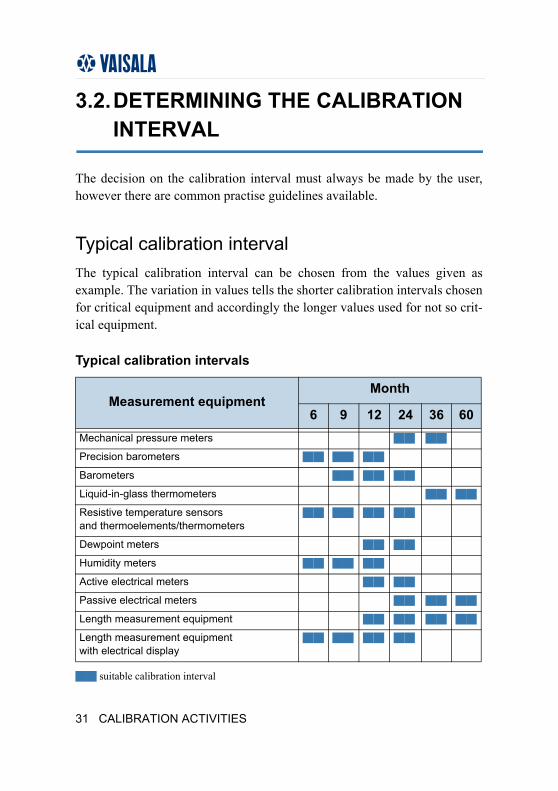
Typical calibration intervalThe typical calibration interval can be chosen from the values given as example. The variation in values tells the shorter calibration intervals chosen for critical equipment and accordingly the longer values used for not so crit-ical equipment.
Typical calibration intervals
suitable calibration interval
Measurement equipment Month
6 9 12 24 36 60Mechanical pressure meters
Precision barometers
Barometers
Liquid-in-glass thermometers
Resistive temperature sensors and thermoelements/thermometers
Dewpoint meters
Humidity meters
Active electrical meters
Passive electrical meters
Length measurement equipment
Length measurement equipment with electrical display
31 CALIBRATION ACTIVITIES
CALIBRATION BOOK
Lengthening the calibration intervalWhen the measurement equipment has stability surveillance long enough the calibration interval can be lengthened. Lengthening can be made when there have been at least 3 calibrations performed in a 12 months time period and the unit has remained within specification. Before lengthening the calibra-tion interval, the user should ensure that the maximum calibration intervals were not exceeded, or, that the calibration interval is not lengthened for criti-cal equipment.
The calibration interval can also be lengthened if the equipment is used with other more stable measurement equipment or if the application allows lower accuracy than the manufacturers specifications grant for the normal calibra-tion interval.
Shortening the calibration intervalWhen measurement equipment has drifted more than its specifications allow, the following procedures should be performed:
• In cases where the drift is caused by misuse or breakage, the cause and fault should be corrected.
• In cases where the unit has drifted without a clear cause, the calibration interval should be shortened to half of its original length.
• Consider whether the calibration intervals of other similar equipment should be shortened.
CALIBRATION ACTIVITIES 32
3.3.CHOOSING CALIBRATION POINTS
A one-point calibration is a typical on-site calibration. It is a good stability monitoring check to be made between full calibrations. The one-point cali-bration may be used to adjust the equipment using an offset-correction.
A full calibration should cover the entire measurement range with 5 or more points equally spaced to verify the linearity of the unit. The calibrated range can be smaller than the actual measurement range if the equipment is used within the limited range. In such a case it is good practise to somehow iden-tify the range the unit is calibrated to since it must not be used outside the calibrated range.
Sensors having hysteresis should be calibrated using increasing and decreas-ing values with equal change rates of the quantity and stabilization times.
3.4.CALIBRATION METHODS BY THE USER
There are numerous ways to calibrate measurement equipment. Manufactur-ers of measurement equipment develop what they may consider the best method for specific equipment. Calibration laboratories that provide services for all equipment measuring a certain quantity have their own internal cali-bration methods. Metrologists that focus strictly on calibration develop pro-cedures and equipment that solely aim to achieve the lowest possible uncertainties.
Whatever method is chosen it should be based on a proper understanding of the requirements in relation to traceability, accuracy and costs.
Users of measurement equipment that are interested in performing calibra-tion themselves must either purchase or develop their own calibration equip-ment. Purchasing of calibration equipment should be considered a major investment.
33 CALIBRATION ACTIVITIES
CALIBRATION BOOK
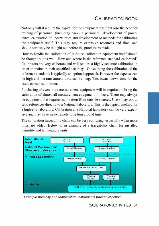
Not only will it require the capital for the equipment itself but also the need for training of personnel (including back-up personnel), development of proce-dures, calculation of uncertainties and development of methods for calibrating the equipment itself. This may require extensive resources and time, and should seriously be thought out before the purchase is made.How to handle the calibration of in-house calibration equipment itself should be thought out as well. How and where is the reference standard calibrated? Calibrators are very elaborate and will require a highly accurate calibration in order to maintain their specified accuracy. Outsourcing the calibration of the reference standards is typically an optimal approach. However the expense can be high and the turn around time can be long. This means down time for the users normal calibration.Purchasing of even more measurement equipment will be required to bring the calibration of almost all measurement equipment in house. There may always be equipment that requires calibration from outside sources. Users may opt to send references directly to a National laboratory. This is the typical method for a high-end laboratory. Calibration at a National laboratory can be very expen-sive and may have an extremely long turn around time. The calibration traceability chain can be very confusing, especially when more links are added. Below is an example of a traceability chain for installed humidity and temperature units.
Example humidity and temperature instruments traceability chain
CALIBRATION ACTIVITIES 34
Temperature equilibriumThe often spoken term “temperature equilibrium” is important but usually impossible to reach in most calibrations. When temperature equilibrium occurs, all of the components in the system are at same temperature and no heat flows occur.
Usually there are heat-producing elements in the system like motors, elec-tronics, operator or light sources. Also note that the heat radiated from the operator´s body is a heat producing element.
To minimize the errors due to temperature differences, the system should be allowed to stabilize for a sufficient amount of time, so that all parts of the system have reached their own equilibrium:
• Ensure that the electronics have been powered long enough to reach their nominal operating temperature.
• Ensure that the environment is stable, air conditioning and lights on, no spot lights or direct sun shining into the measurement area.
• The number and variation of people in the measurement area is limited to a minimum, and the measurement system is protected from the heat pro-duced by the operator if needed.
Stabilization and samplingAfter new measurement point is adjusted the whole calibration system and the sensors must be stabilized before measurement.
Different parts of the system stabilize at different rates. The whole system should be stabilized before measurements are made. In cases where only the reference is monitored and found to be stable the Unit Under Calibration (UUC) may still be not stabilized.
In cases where the measurement system is not stable, sampling should be used to ensure a good representation of the quantity being measured, not just a single measurement at one point.
35 CALIBRATION ACTIVITIES
CALIBRATION BOOK
The number of samples should be large enough. Typically ten samples are adequate but if the system has a lot of variations, up to 100 samples at a rea-sonable interval should be taken to cover the full variation.
Uncertainty estimationUncertainty comes from three main sources: The reference used, the unit under calibration (UUC) itself and the calibration process used.
Below are listed some of the uncertainty factors.
• Uncertainty of the reference is composed of calibration uncertainty, long-term and short-term stability, resolution and the effect of influence quanti-ties.
• Uncertainty of the UUC is composed of repeatability, linearity, hysteresis and short-term stability, resolution and the influence quantities.
• The calibration process itself may cause uncertainty; like the uncertainty of the height correction used in a pressure calibration, the temperature uni-formity in a climate chamber during a temperature calibration or the pres-sure correction used in a dewpoint calibration. For more information, see Appendix C.
CALIBRATION ACTIVITIES 36
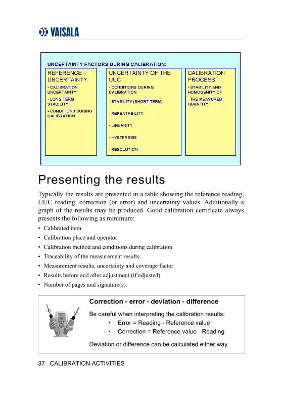
Presenting the resultsTypically the results are presented in a table showing the reference reading, UUC reading, correction (or error) and uncertainty values. Additionally a graph of the results may be produced. Good calibration certificate always presents the following as minimum:• Calibrated item• Calibration place and operator• Calibration method and conditions during calibration• Traceability of the measurement results• Measurement results, uncertainty and coverage factor• Results before and after adjustment (if adjusted)• Number of pages and signature(s).
Correction - error - deviation - difference
Be careful when interpreting the calibration results: • Error = Reading - Reference value• Correction = Reference value - Reading
Deviation or difference can be calculated either way.
37 CALIBRATION ACTIVITIES
CALIBRATION BOOK
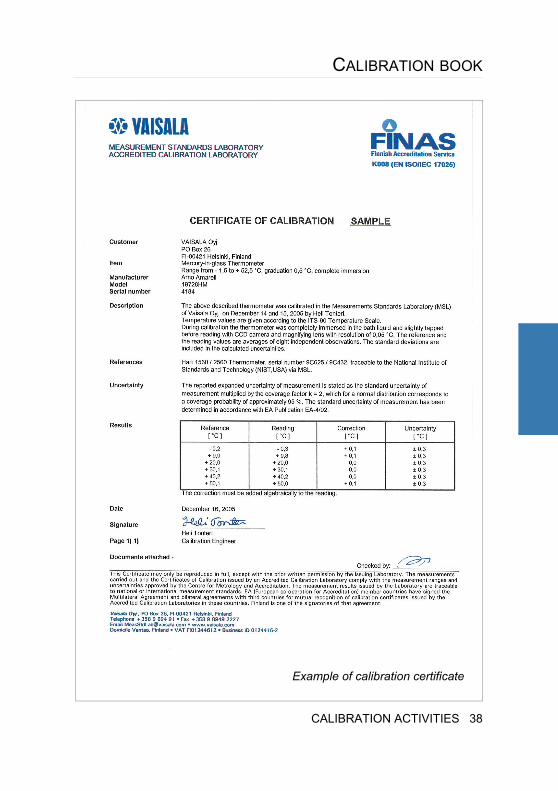
Example of calibration certificate
CALIBRATION ACTIVITIES 38
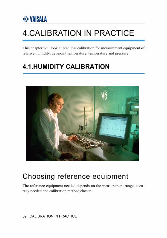
4.CALIBRATION IN PRACTICE
This chapter will look at practical calibration for measurement equipment of relative humidity, dewpoint temperature, temperature and pressure.
4.1.HUMIDITY CALIBRATION
Choosing reference equipmentThe reference equipment needed depends on the measurement range, accu-racy needed and calibration method chosen.
39 CALIBRATION IN PRACTICE
CALIBRATION BOOK
Moist air (gas) generation methods
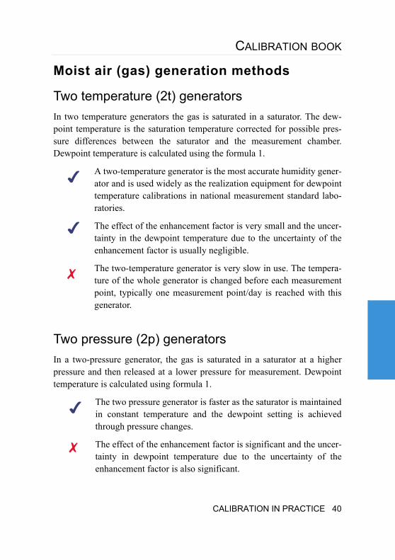
Two temperature (2t) generatorsIn two temperature generators the gas is saturated in a saturator. The dew-point temperature is the saturation temperature corrected for possible pres-sure differences between the saturator and the measurement chamber. Dewpoint temperature is calculated using the formula 1.
A two-temperature generator is the most accurate humidity gener-ator and is used widely as the realization equipment for dewpoint temperature calibrations in national measurement standard labo-ratories.
The effect of the enhancement factor is very small and the uncer-tainty in the dewpoint temperature due to the uncertainty of the enhancement factor is usually negligible.
The two-temperature generator is very slow in use. The tempera-ture of the whole generator is changed before each measurement point, typically one measurement point/day is reached with this generator.
Two pressure (2p) generatorsIn a two-pressure generator, the gas is saturated in a saturator at a higher pressure and then released at a lower pressure for measurement. Dewpoint temperature is calculated using formula 1.
The two pressure generator is faster as the saturator is maintained in constant temperature and the dewpoint setting is achieved through pressure changes.
The effect of the enhancement factor is significant and the uncer-tainty in dewpoint temperature due to the uncertainty of the enhancement factor is also significant.
CALIBRATION IN PRACTICE 40
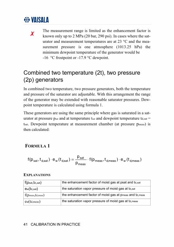
The measurement range is limited as the enhancement factor is known only up to 2 MPa (20 bar, 290 psi). In cases where the sat-urator and measurement temperatures are at 23 °C and the mea-surement pressure is one atmosphere (1013.25 hPa) the minimum dewpoint temperature of the generator would be -16 °C frostpoint or -17.9 °C dewpoint.
Combined two temperature (2t), two pressure (2p) generatorsIn combined two temperature, two pressure generators, both the temperature and pressure of the saturator are adjustable. With this arrangement the range of the generator may be extended with reasonable saturator pressures. Dew-point temperature is calculated using formula 1.
These generators are using the same principle where gas is saturated in a sat-urator at pressure psat and at temperature tsat and dewpoint temperature td,sat = tsat. Dewpoint temperature at measurement chamber (at pressure pmeas) is then calculated:
EXPLANATIONS
f(psat,td,sat) the enhancement factor of moist gas at psat and td,sat
ew(td,sat) the saturation vapor pressure of moist gas at td,sat
f(pmeas,td,meas) the enhancement factor of moist gas at pmeas and td,meas
ew(td,meas) the saturation vapor pressure of moist gas at td,meas
FORMULA 1
)t(e)t,p(fp
p)t(e)t,p(f meas,dwmeas,dmeas
meas
satsat,dwsat,dsat ⋅⋅=⋅
41 CALIBRATION IN PRACTICE
CALIBRATION BOOK
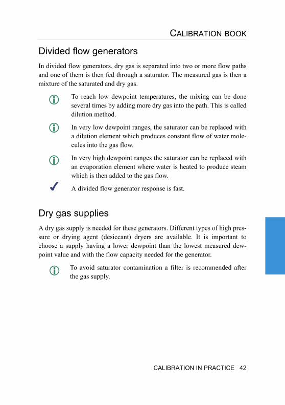
Divided flow generatorsIn divided flow generators, dry gas is separated into two or more flow paths and one of them is then fed through a saturator. The measured gas is then a mixture of the saturated and dry gas.
To reach low dewpoint temperatures, the mixing can be done several times by adding more dry gas into the path. This is called dilution method.
In very low dewpoint ranges, the saturator can be replaced with a dilution element which produces constant flow of water mole-cules into the gas flow.
In very high dewpoint ranges the saturator can be replaced with an evaporation element where water is heated to produce steam which is then added to the gas flow.
A divided flow generator response is fast.
Dry gas suppliesA dry gas supply is needed for these generators. Different types of high pres-sure or drying agent (desiccant) dryers are available. It is important to choose a supply having a lower dewpoint than the lowest measured dew-point value and with the flow capacity needed for the generator.
To avoid saturator contamination a filter is recommended after the gas supply.
CALIBRATION IN PRACTICE 42
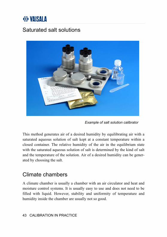
Saturated salt solutions
This method generates air of a desired humidity by equilibrating air with a saturated aqueous solution of salt kept at a constant temperature within a closed container. The relative humidity of the air in the equilibrium state with the saturated aqueous solution of salt is determined by the kind of salt and the temperature of the solution. Air of a desired humidity can be gener-ated by choosing the salt.
Climate chambersA climate chamber is usually a chamber with an air circulator and heat and moisture control systems. It is usually easy to use and does not need to be filled with liquid. However, stability and uniformity of temperature and humidity inside the chamber are usually not so good.
Example of salt solution calibrator
43 CALIBRATION IN PRACTICE
CALIBRATION BOOK
Reference equipment
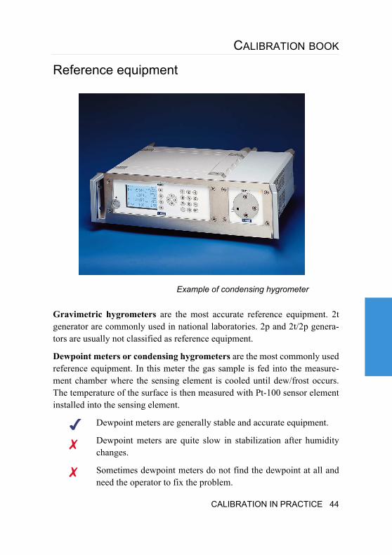
Gravimetric hygrometers are the most accurate reference equipment. 2t generator are commonly used in national laboratories. 2p and 2t/2p genera-tors are usually not classified as reference equipment.
Dewpoint meters or condensing hygrometers are the most commonly used reference equipment. In this meter the gas sample is fed into the measure-ment chamber where the sensing element is cooled until dew/frost occurs. The temperature of the surface is then measured with Pt-100 sensor element installed into the sensing element.
Dewpoint meters are generally stable and accurate equipment.
Dewpoint meters are quite slow in stabilization after humidity changes.
Sometimes dewpoint meters do not find the dewpoint at all and need the operator to fix the problem.
Example of condensing hygrometer
CALIBRATION IN PRACTICE 44
In ranges from 0 to -20 °C the dew may be in the form of water, or ice, or both, which may cause significant error if it is not notified.
Dewpoint meters need periodic cleaning.
Dewpoint meters may need an additional cooling system for the lowest measurement points.
The temperature of the additional coolant may affect the dew-point meter reading causing significant errors.
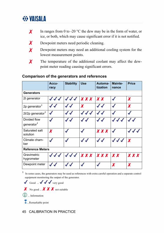
Comparison of the generators and references
¹ In some cases, the generators may be used as references with extra careful operation and a separate control equipment monitoring the output of the generator.
Good ... very good
No good ... not suitable
... Information
...Remarkable point
Accu-racy
Stability Use Automa-tization
Mainte-nance
Price
Generators
2t generator
2p generator¹2t/2p generator¹Divided flow generator¹Saturated salt solution
Climate cham-ber
Reference Meters
Gravimetric hygrometer
Dewpoint meter
45 CALIBRATION IN PRACTICE
CALIBRATION BOOK
Relative humidity calibration
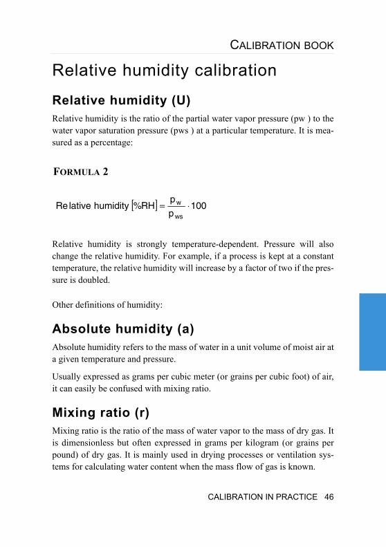
Relative humidity (U)Relative humidity is the ratio of the partial water vapor pressure (pw ) to the water vapor saturation pressure (pws ) at a particular temperature. It is mea-sured as a percentage:
Relative humidity is strongly temperature-dependent. Pressure will also change the relative humidity. For example, if a process is kept at a constant temperature, the relative humidity will increase by a factor of two if the pres-sure is doubled.
Other definitions of humidity:
Absolute humidity (a)Absolute humidity refers to the mass of water in a unit volume of moist air at a given temperature and pressure.
Usually expressed as grams per cubic meter (or grains per cubic foot) of air, it can easily be confused with mixing ratio.
Mixing ratio (r)Mixing ratio is the ratio of the mass of water vapor to the mass of dry gas. It is dimensionless but often expressed in grams per kilogram (or grains per pound) of dry gas. It is mainly used in drying processes or ventilation sys-tems for calculating water content when the mass flow of gas is known.
FORMULA 2
[ ] 100p
pRH%humiditylativeRe
ws
w ⋅=
CALIBRATION IN PRACTICE 46
Saturation vapor pressure of water (pws)The maximum pressure that water vapor can exist at a particular tempera-ture. The higher the temperature, the more water vapor the gas can hold.
Dewpoint temperature (td)Dewpoint is the temperature at which air becomes saturated when cooled and begins to condense, forming dew. At 100 % relative humidity the ambi-ent temperature equals the dewpoint temperature. The lower the dewpoint temperature as compared to the ambient temperature, the less the risk of con-densation and consequently, the drier the gas. Dewpoint is not temperature dependent, but it is affected by pressure.
Frostpoint temperature (tf)If the dewpoint temperature is below freezing, the term frostpoint tempera-ture is sometimes used. Frostpoint temperature is always higher than dew-point temperature for the same humidity. This is because the saturation vapor pressure of ice is smaller than the saturation vapor pressure of water.
Relative humidity calibration methods
PreparationsPerform a chemical purge if the sensor has this function. Allow the humidity sensor to stabilize to laboratory conditions.
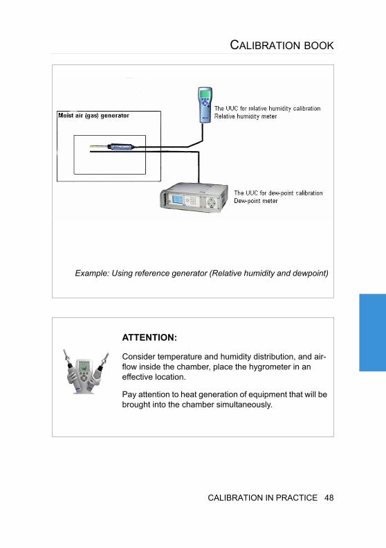
Using a moist air (gas) generator as referencePlace the UUC into the chamber of a humidity generator, or, supply moist air (gas) generated by a humidity generator into the UUC. This enables compar-ing the indicated value of the UUC in order to calibrate it to the value of the humidity generator.
47 CALIBRATION IN PRACTICE
CALIBRATION BOOK
Example: Using reference generator (Relative humidity and dewpoint)
ATTENTION:
Consider temperature and humidity distribution, and air-flow inside the chamber, place the hygrometer in an effective location.
Pay attention to heat generation of equipment that will be brought into the chamber simultaneously.
CALIBRATION IN PRACTICE 48
Using a dewpoint meter or hygrometer as reference
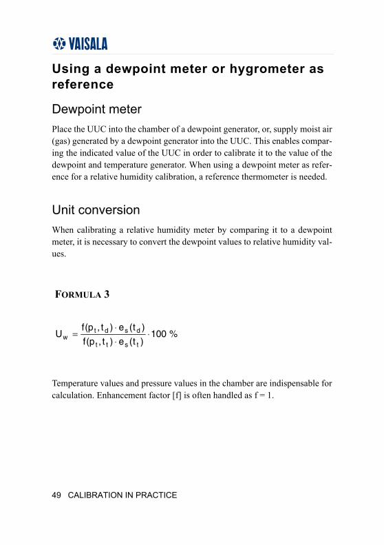
Dewpoint meterPlace the UUC into the chamber of a dewpoint generator, or, supply moist air (gas) generated by a dewpoint generator into the UUC. This enables compar-ing the indicated value of the UUC in order to calibrate it to the value of the dewpoint and temperature generator. When using a dewpoint meter as refer-ence for a relative humidity calibration, a reference thermometer is needed.
Unit conversion When calibrating a relative humidity meter by comparing it to a dewpoint meter, it is necessary to convert the dewpoint values to relative humidity val-ues.
Temperature values and pressure values in the chamber are indispensable for calculation. Enhancement factor [f] is often handled as f = 1.
FORMULA 3
%100)t(e)t,p(f
)t(e)t,p(fU
tstt
dsdtw ⋅
⋅⋅
=
49 CALIBRATION IN PRACTICE
CALIBRATION BOOK
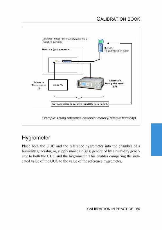
HygrometerPlace both the UUC and the reference hygrometer into the chamber of a humidity generator, or, supply moist air (gas) generated by a humidity gener-ator to both the UUC and the hygrometer. This enables comparing the indi-cated value of the UUC to the value of the reference hygrometer.
Example: Using reference dewpoint meter (Relative humidity)
CALIBRATION IN PRACTICE 50
One-point calibrationIn a one-point calibration the reference sensor and calibrated sensor are placed closely together in a stable environment. After stabilization the read-ings can be taken. A one-point calibration may also be done in a process where the reference sensor is placed near the UUC sensor in actual process conditions.
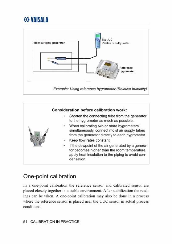
Example: Using reference hygrometer (Relative humidity)
Consideration before calibration work:• Shorten the connecting tube from the generator
to the hygrometer as much as possible.• When calibrating two or more hygrometers
simultaneously, connect moist air supply tubes from the generator directly to each hygrometer.
• Keep flow rates constant.• If the dewpoint of the air generated by a genera-
tor becomes higher than the room temperature, apply heat insulation to the piping to avoid con-densation.
51 CALIBRATION IN PRACTICE
CALIBRATION BOOK
In case the one-point calibration is made in room conditions the reference and calibrated sensor must be protected from direct light sources, like light-ing or sun, and stabilization should be ensured with a fan circulating air to the sensors.
Full calibrationTo perform a full range calibration, controlled temperature, and humidity generation equipment are needed. They may be a humidity generator, cli-mate chamber or a saturated salt solution calibrator.
In a full calibration, the measurement points (usually 3 or more points) are selected equally spaced throughout the measurement range and usually per-formed from the lowest humidity to the highest humidity. These measure-ments are then repeated backwards from the highest humidity to the lowest humidity.
Common mistakes
Temperature equilibrium is not reached:In case the Unit Under Calibration (UUC) has been recently moved from some other environment into the measurement environment, it may not have had sufficient time to stabilize to the temperature of the measurement condi-tions. This may cause up to 6 %/ °C error in the relative humidity value.
Stabilization time is not sufficient:After changing the humidity value of the reference, the UUC must have enough stabilization time at the new humidity value (sometimes the equip-ment may have very different response or stabilization times).
CALIBRATION IN PRACTICE 52
Hysteresis is not taken into account:Some sensors have significant hysteresis behavior. Significant errors may occur if the measurements are carried out by only changing the humidity val-ues in one direction.
The temperature or humidity is measured in a different location than the UUC sensor:An error will occur if there is temperature difference between the reference sensor and the UUC sensor.
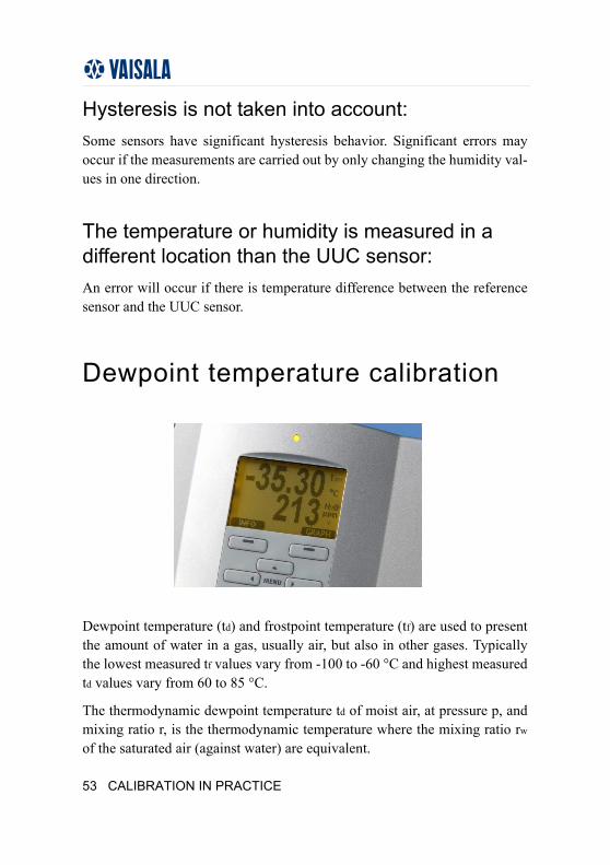
Dewpoint temperature calibration
Dewpoint temperature (td) and frostpoint temperature (tf) are used to present the amount of water in a gas, usually air, but also in other gases. Typically the lowest measured tf values vary from -100 to -60 °C and highest measured td values vary from 60 to 85 °C.
The thermodynamic dewpoint temperature td of moist air, at pressure p, and mixing ratio r, is the thermodynamic temperature where the mixing ratio rw
of the saturated air (against water) are equivalent.
53 CALIBRATION IN PRACTICE
CALIBRATION BOOK
The correspondence between dewpoint temperature td, mixing ratio r and pressure p is:
EXPLANATIONS
e'w(td) saturation vapor pressure of saturated air (against water) at dewpoint temperature td
e'w(tf) saturation vapor pressure of saturated air (against ice) at frostpoint temperature tf
Mv molar mass of water vapor
Ma molar mass of dry air
xv mole fraction of the water vapor
FORMULA 4
)t,p(rr dw=
FORMULA 5
pxpr
M
Mr
)t(eorpxpr
M
Mr
)t(e v
a
vfwv
a
vdw ⋅=⋅
+=′⋅=⋅
+=′
CALIBRATION IN PRACTICE 54
Dewpoint temperature calibration methodsDewpoint temperature calibration is a typical comparison calibration where the reading of the UUC is compared to the value of reference generator or reference meter at selected dewpoint temperatures.
PreparationsBefore calibration the entire measurement system must be purged of water vapor. Usually, this is done by flushing the system with dry gas. The drying process can be accelerated by heating the tubing during flushing.
The measurement system, tubing and fittings must be of a suit-able material for the measurement range. For the lowest dew-points, use electro-polished stainless steel tubing with a minimum number of fittings, preferably welded connections or leak free fitting types.
If the measured dewpoint temperature is near or above room temperature, heat the system before starting humidity generation to avoid condensation in the system.
CalibrationSelect the measurement points (usually 3 or more points) equally spaced throughout the measurement range. The calibration is usually performed beginning with the lowest dewpoint temperature and proceeding to the high-est dewpoint temperature. The measurement of hysteresis with condensing type dewpoint meters is not necessary. Other type sensors would need the hysteresis measurement but it is difficult to produce at the lowest dewpoint temperatures due to extremely long stabilization times. In these cases the hysteresis should be estimated and added into the uncertainty estimations.
After changing the dewpoint temperature the stabilization time must be suf-ficient to allow the measurement system, reference and the UUC to reach equilibrium.
55 CALIBRATION IN PRACTICE
CALIBRATION BOOK
Common mistakes
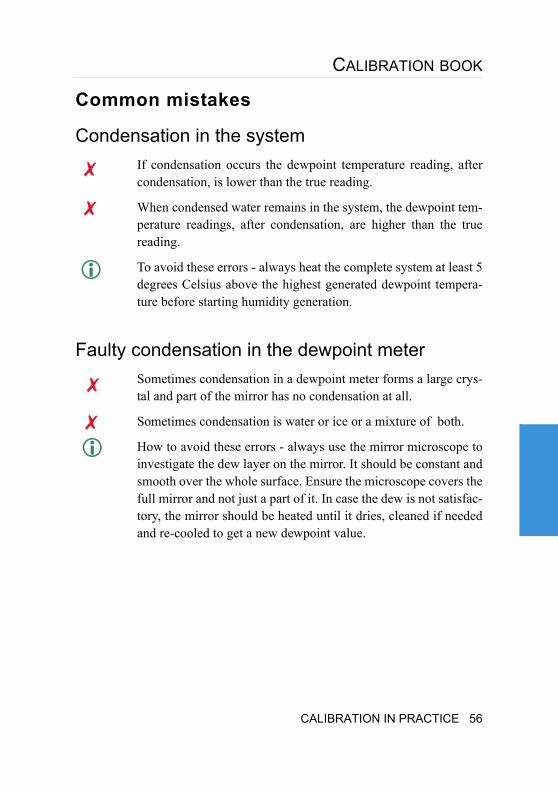
Condensation in the systemIf condensation occurs the dewpoint temperature reading, after condensation, is lower than the true reading.
When condensed water remains in the system, the dewpoint tem-perature readings, after condensation, are higher than the true reading.
To avoid these errors - always heat the complete system at least 5 degrees Celsius above the highest generated dewpoint tempera-ture before starting humidity generation.
Faulty condensation in the dewpoint meterSometimes condensation in a dewpoint meter forms a large crys-tal and part of the mirror has no condensation at all.
Sometimes condensation is water or ice or a mixture of both.
How to avoid these errors - always use the mirror microscope to investigate the dew layer on the mirror. It should be constant and smooth over the whole surface. Ensure the microscope covers the full mirror and not just a part of it. In case the dew is not satisfac-tory, the mirror should be heated until it dries, cleaned if needed and re-cooled to get a new dewpoint value.
CALIBRATION IN PRACTICE 56
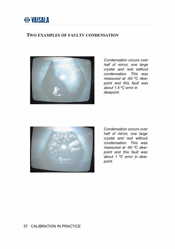
Condensation occurs over half of mirror, one large crystal and rest without condensation. This was measured at -60 ºC dew-point and this fault was about 1.5 ºC error in dewpoint.
Condensation occurs over half of mirror, one large crystal and rest without condensation. This was measured at -60 ºC dew-point and this fault was about 1 ºC error in dew-point.
TWO EXAMPLES OF FAULTY CONDENSATION
57 CALIBRATION IN PRACTICE
CALIBRATION BOOK
4.2.TEMPERATURE CALIBRATION
Thermodynamic Temperature (T90) is one of the basic units in The Interna-tional System of Units (SI) and the Kelvin [K] is a basic unit.
Kelvin is defined using the following equation:
EXPLANATIONS
Ttp the thermodynamic temperature at the Triple Point of Water [K]
Celsius and Fahrenheit (t)
derived quantities in The International System of Units (SI) and they are defined using the following equations (formula 7 and 8)
FORMULA 6
16.273
TK1 tp=
CALIBRATION IN PRACTICE 58
As the thermodynamic temperature itself is not a practical unit of measure-ment, the realization of temperature is made using the International Temper-ature Scale, ITS-90. The scale is based on so called fixed points like triple points, freezing points or melting points of pure materials. The thermody-namic temperatures at these points are determined experimentally and the values are agreed upon by all that are using this scale. Between these points so called interpolation equipment are used, in range from -259 to 962 °C a 25.5 ohm Standard Platinum Resistance Thermometer (SPRT) is used. This is a specially designed and manufactured platinum thermometer that follows closely the interpolation equations presented in the ITS-90. Typically SPRT 25 is used up to 420 °C or 660 °C and a specially designed High Tempera-ture Platinum Resistance Thermometer (HTPRT) is used at the higher tem-peratures.
ITS-90 Temperature ScaleBetween 0.65 K and 5.0 K, T90 is defined in terms of the vapor-pressure tem-perature relations of £He and ¢He.
Between 3.0 K and the triple point of neon (24.5561 K), T90 is defined by means of a helium gas thermometer calibrated at three experimentally realiz-able temperatures having assigned numerical values (defining fixed points) and using specified interpolation procedures.
[ ] [ ] K15.273KTCt −=°
FORMULA 7
FORMULA 8
[ ] [ ] 32Ct8.1Ft +°⋅=°
59 CALIBRATION IN PRACTICE
CALIBRATION BOOK
Between the triple point of equilibrium hydrogen (13.8033 K) and the freez-ing point of silver (961.78 °C) T90 is defined by means of Standard Platinum Resistance Thermometers calibrated at specified sets of defining fixed points and using specified interpolation procedures.
Above the freezing point of silver (961.78 °C) T90 is defined in terms of a defining fixed point and the Planck radiation law.
Choosing reference equipmentThe reference equipment needed depends on the accuracy needed and the calibration method chosen. In the case of a one-point calibration only a refer-ence thermometer is needed. In case of a fixed-point calibration or a full cal-ibration, temperature generation equipment is also needed.
Lots of different thermometers are available. Typically resistive sensors, either platinum sensors or thermistors are used as the sensor, and they are attached to a display unit or digital multimeter.
Liquid-in-glass thermometers may also be used. Thermocouples are used as references only at higher temperatures.
Radiation thermometers are developing rapidly and can already be used from room temperature up to extremely high temperatures. The accuracy of those is however limited and in this book we are not considering them as ref-erence equipment.
Temperature generation methods
Fixed pointsFixed point calibration should be chosen when the best available accuracy is needed.
CALIBRATION IN PRACTICE 60
In a full fixed-point calibration, the points needed for each range are defined and the interpolation equations are given in the ITS-90 scale documentation.
Sometimes it is practical to use one or a few fixed points as regu-lar in-house stability test. If drift in the sensor is observed, then send the sensor for a full calibration.
In cases where fixed-point calibration was chosen, the full sys-tem should be chosen to support the highest accuracy calibra-tions.
The best available accuracy is achieved with Fixed Points.
Fixed Points are expensive and complex to use.
Calibration BathsCalibration baths are usually specially designed baths or tanks with a deep chamber and high circulation using alcohol, water or oil as a medium, depending on the temperature. Salt is also used at the highest temperatures. Specially designed, so-called, Micro Baths are also available for smaller thermometers.
The best available stability and uniformity of temperature is achieved with the best calibration baths.
The stability of the bath may be improved with a specially designed temperature stabilization block.
Each sensor should be tested for optimum immersion. Test is done by simply calibrating the end points while immersing the sensor, for example, at 5 cm increments. Once the results remain the same for the next immersion level, the correct immersion level has been found for this kind of sensor.
Some thermometer sensors are not immersible into a liquid medium without proper protection.
61 CALIBRATION IN PRACTICE
CALIBRATION BOOK
Climate chamberA climate chamber is usually a chamber with an air circulator and a heat control system. Sometimes, humidity may also be controlled.
A climate chamber is usually easy to use and does not need any liquid filling.
A climate chamber is suitable for the calibration of large ther-mometers. With a window on the door they also can be used for chart recorders or thermometers having only a visual display.
Stability and uniformity of temperature inside the chamber is usually poor.
Stability and uniformity of temperature inside the chamber may be improved by placing a special measurement chamber inside the climate chamber.
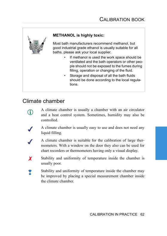
METHANOL is highly toxic:
Most bath manufacturers recommend methanol, but good industrial grade ethanol is usually suitable for all baths, please ask your local supplier.
• If methanol is used the work space should be ventilated and the bath operators or other peo-ple should not be exposed to the fumes during filling, operation or changing of the fluid.
• Storage and disposal of all the bath fluids should be done according to the local regula-tions.
CALIBRATION IN PRACTICE 62
Dry block calibratorsA dry block calibrator is a small calibration furnace with a verti-cal well for thermometer sensors and they usually have a very low immersion depth. The measurement range is usually from room temperature up to 650 °C but some equipment can go down to -40 °C.
The dry block calibrator is portable, usually easy to use and does not need any liquid filling.
Low immersion depth, suitable only for very thin sensors.
OvensOvens are used at higher temperatures. Only specially designed vertical calibration ovens with several temperature controlled zones should be used for calibration.
Ovens reach the highest calibration temperatures.
An oven without air circulation will have high temperature gradi-ents and the gradients should be investigated carefully before use.
Temperature sensing equipment
SPRT ThermometersSPRT thermometers are resistive sensors with typically 25.1 to 25.5 Ω nom-inal resistance to used in the range from -259 to 962 °C.
The best available temperature measurement accuracy is achieved with an SPRT-25 thermometer calibrated at fixed points.
63 CALIBRATION IN PRACTICE
CALIBRATION BOOK
The best available temperature measurement accuracy is achieved with an SPRT-25 thermometer calibrated at fixed points.
An SPRT thermometer is an extremely fragile piece of equip-ment and needs careful operation.
An SPRT-25 thermometer usually requires the use of the triple point of water.
Calculations of SPRT-25 thermometer are complex.
Needs an accurate resistance measurement bridge.
Pt-100 sensor or Precision ThermistorPt-100 sensors or precision thermistors are generally used in the range from -100 to 200 °C.
Pt-100 sensors or precision thermistors are usually robust and easy to use.
Stability of a Pt-100 sensor is not known before it has undergone several calibrations.
Stability of the sensors may be monitored with regular calibra-tions at ice-point (0.00 °C).
Liquid-in-glass thermometersLiquid-in-glass thermometers may be used in the range from -200 to 500 °C.
In liquid-in-glass thermometers, the expansion of a selected liq-uid in comparison to temperature is used to measure temperature. The liquid may be an organic liquid in the lowest temperatures, for example mercury/thallium down to -56 °C and mercury down to -38 °C.
CALIBRATION IN PRACTICE 64
Liquid-in-glass thermometers are generally stable allowing up to a three year calibration interval.
The use of mercury is not allowed in several countries.
Liquid-in-glass thermometers are fragile and the measurement range is limited.
Liquid-in-glass thermometers are usually used as a pair of two thermometers.
Different kinds of liquids are used, but only mercury or mercury/thallium thermometers are reliable.
Liquid-in-glass thermometers are difficult to read and require a trained observer.
Temperature display unitsIn cases where the sensor has an electrical output, it is usually measured with a resistance bridge, thermometer display unit or digital multimeter.
Resistance bridgesIn a resistance bridge, the measured resistance is compared to a reference resistance, either internal or external.
A conventional resistance bridge is manual but modern bridges are possible to automate.
Most accurate resistance measurement method.
Does not give direct temperature readings.
Needs calibrated reference resistance.
65 CALIBRATION IN PRACTICE
CALIBRATION BOOK
Thermometer display unitsThere are many different specially designed thermometer display units to choose from.
If the Pt-100 sensor or thermistor is connected to a thermometer, they should be calibrated as a pair, and the calibration coeffi-cients stored in the memory of the thermometer.
Gives direct temperature reading, no additional calculations needed.
Digital multimetersA digital multimeter may be used to measure the resistance of the tempera-ture sensor.
If the resistance of the Pt-100 sensor or thermistor is measured during the calibration with multimeter and the coefficients for the calibration equation are given on the certificate, the following should be taken into consideration:
•Proper calibration of the resistance range of the multimeter.
•The measurement current should not exceed the recommended cur-rent of the sensor to avoid self-heating.
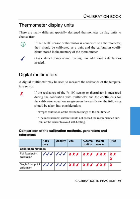
Comparison of the calibration methods, generators and references
Accu-racy
Stability Use Automa-tization
Mainte-nance
Price
Calibration methods
Full fixed point calibration
Single fixed point calibration
CALIBRATION IN PRACTICE 66
Good ... very good
No good ... not suitable
... Information
...Remarkable point
Comparison cali-bration in bath
Temperature generation
Fixed points
Calibration baths
Climate chamber
Dry block calibrator
Ovens
Reference sensor
SPRT thermom-eter
Pt-100 sensor or precision ther-mistor
Liquid-in-glass thermometer
Display unit
Resistance bridge
Thermometer
Digital multimeter
Accu-racy
Stability Use Automa-tization
Mainte-nance
Price
67 CALIBRATION IN PRACTICE
CALIBRATION BOOK
Temperature calibration methodsA temperature calibration may be a fixed point calibration, or, a comparison calibration, where the reference value and the UUC value are compared at selected temperatures.
A temperature calibration may be done as a one-point calibration, or, a full range calibration. Sometimes it is also practical to calibrate the UUC for only part of the measurement range, if the overall range is larger than the temperature range used.
Fixed point calibrationIn a fixed point calibration, the reference is a so-called fixed point cell which when operated properly produces a fixed temperature value. The cell has a thermometer well into which the sensor is placed and the reading taken.
Several fixed point values may be measured and the coefficients solved for the correction equation.
The most common fixed point is the triple point of water which produces temperature of 0.01 °C. Traditionally ice-point (0.00 °C) is used like a fixed point but it does not have that status in ITS-90 scale.
One-point calibrationTraditionally the ice-point (0.00 °C) is used as a control or adjustment point for some thermometers.
The stability of liquid-in-glass thermometers and platinum sensors are con-trolled with frequent ice-point measurements and appropriate corrections calculated.
In one-point calibration the reference sensor and UUC sensor are placed closely together in a stable temperature environment. After stabilization the readings are taken. A one-point calibration may also be done in a process where the reference sensor is placed near the UUC sensor in actual process conditions.
CALIBRATION IN PRACTICE 68
In cases where the one-point calibration is made at room temperature the ref-erence and calibrated sensor must be protected from direct light sources, like lighting or sun, and stabilization should be ensured with a fan circulating air to the sensors.
Full calibrationTo perform a full range calibration, a controlled temperature generator is needed. This may be a calibration bath, climate chamber or dry block cali-brator.
In full calibration the measurement points (usually 3 or more points) are selected equally spaced throughout the measurement range. These are usu-ally performed beginning with the lowest temperature and proceeding to the highest temperature. Hysteresis of modern temperature sensors is negligible and does not need to be measured.
After changing the temperature set-point, the stabilization time must be suf-ficient to allow the medium, reference and the UUC to reach equilibrium.
Calibration in a fixed point cellThe UUC sensor is immersed into the thermometer well of the fixed cell, the cell is prepared and the reading of the UUC sensor is taken.
Sensor construction and dimensions should be suitable to fixed point calibration.
Calibration in calibration bathThe reference and UUC sensor are immersed into the bath, and after stabili-zation, the reading of the reference and UUC sensor are taken.
Sensor construction and dimensions should be suitable for bath calibration.
The sensor may have to be protected before immersing into the bath liquid.
69 CALIBRATION IN PRACTICE
CALIBRATION BOOK
Calibration in climate chamber or dry block calibratorThe reference and UUC sensor are placed into the calibration chamber and after stabilization, the reading of the reference and UUC sensors are taken.
In this case, the thermal contact between air and the sensor is weak, in com-parison to a calibration in liquid, and heat conducted through the connecting wires may cause large errors.
Common mistakes
System not stabilized before measurementIn cases where system is not stabilized before taking measure-ments, the reference and the UUC reading may differ signifi-cantly as the sensors have different time constants and follow the change at different rates.
To avoid these errors, carefully wait for the system to stabilize before taking any measurements.
Heat conducted via sensor wiresIn cases where the sensor is not immersed deep enough into the temperature chamber, heat is conducted via the wires and signifi-cant errors can occur. This may happen in baths, dry wells, ovens and climate chambers.
To avoid these errors, calibrate the sensor at end point tempera-tures while immersing the sensor, for example, at 5cm incre-ments. Once the results remain the same for the next immersion level, the correct immersion level has been found for this kind of sensor.
CALIBRATION IN PRACTICE 70
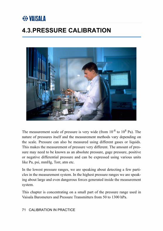
4.3.PRESSURE CALIBRATION
The measurement scale of pressure is very wide (from 10-8 to 108 Pa). The nature of pressures itself and the measurement methods vary depending on the scale. Pressure can also be measured using different gases or liquids. This makes the measurement of pressure very different. The amount of pres-sure may need to be known as an absolute pressure, gage pressure, positive or negative differential pressure and can be expressed using various units like Pa, psi, mmHg, Torr, atm etc.
In the lowest pressure ranges, we are speaking about detecting a few parti-cles in the measurement system. In the highest pressure ranges we are speak-ing about large and even dangerous forces generated inside the measurement system.
This chapter is concentrating on a small part of the pressure range used in Vaisala Barometers and Pressure Transmitters from 50 to 1300 hPa.
71 CALIBRATION IN PRACTICE
CALIBRATION BOOK
The tendency of expansion of a compressed gas or liquid is called pressure p [Pa] and it is defined using equation:
In a system the pressure p is the fraction of the force F [N] caused by the ten-dency of expansion of the compressed gas (or liquid) against surface and the area of that surface A [m2].
Most pressure equipment in this pressure range is measuring force effecting the pressure sensor and calibrated for pressure.
Choosing reference equipmentPressure Balance (known also as Piston Gage), Mercury Manometer or Elec-trical Transfer Standard may be used as reference equipment in the pressure range from 50 hPa to 1300 hPa.
Conventional pressure balanceIn conventional pressure balance weights are loaded on top of a piston. The mass together with the local gravity then that produces downward force. This force causes pressure relative to the area of the piston against the bot-tom of the piston. To measure pressure, the balance pressure supply is con-nected to the bottom of the pressure balance and adjusted so that the piston is floating - at this point the pressure in the system is equal to the pressure pro-duced with the weights and piston.
AF
p =
FORMULA 9
CALIBRATION IN PRACTICE 72
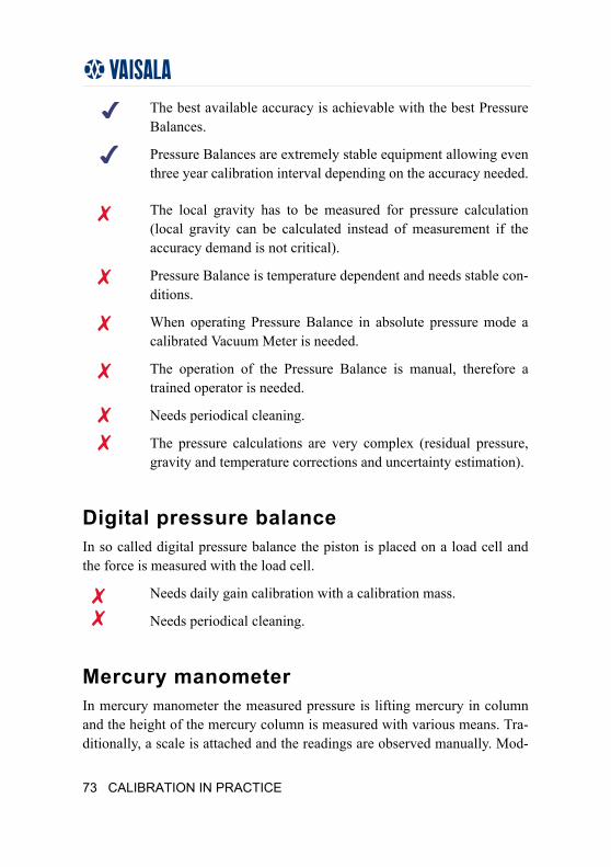
The best available accuracy is achievable with the best Pressure Balances.
Pressure Balances are extremely stable equipment allowing even three year calibration interval depending on the accuracy needed.
The local gravity has to be measured for pressure calculation (local gravity can be calculated instead of measurement if the accuracy demand is not critical).
Pressure Balance is temperature dependent and needs stable con-ditions.
When operating Pressure Balance in absolute pressure mode a calibrated Vacuum Meter is needed.
The operation of the Pressure Balance is manual, therefore a trained operator is needed.
Needs periodical cleaning.
The pressure calculations are very complex (residual pressure, gravity and temperature corrections and uncertainty estimation).
Digital pressure balanceIn so called digital pressure balance the piston is placed on a load cell and the force is measured with the load cell.
Needs daily gain calibration with a calibration mass.
Needs periodical cleaning.
Mercury manometerIn mercury manometer the measured pressure is lifting mercury in column and the height of the mercury column is measured with various means. Tra-ditionally, a scale is attached and the readings are observed manually. Mod-
73 CALIBRATION IN PRACTICE
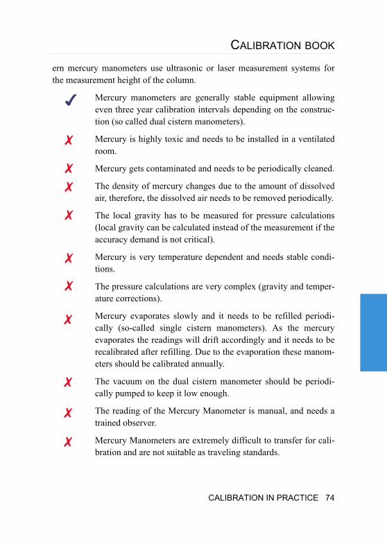
CALIBRATION BOOK
ern mercury manometers use ultrasonic or laser measurement systems for the measurement height of the column.
Mercury manometers are generally stable equipment allowing even three year calibration intervals depending on the construc-tion (so called dual cistern manometers).
Mercury is highly toxic and needs to be installed in a ventilated room.
Mercury gets contaminated and needs to be periodically cleaned.
The density of mercury changes due to the amount of dissolved air, therefore, the dissolved air needs to be removed periodically.
The local gravity has to be measured for pressure calculations (local gravity can be calculated instead of the measurement if the accuracy demand is not critical).
Mercury is very temperature dependent and needs stable condi-tions.
The pressure calculations are very complex (gravity and temper-ature corrections).
Mercury evaporates slowly and it needs to be refilled periodi-cally (so-called single cistern manometers). As the mercury evaporates the readings will drift accordingly and it needs to be recalibrated after refilling. Due to the evaporation these manom-eters should be calibrated annually.
The vacuum on the dual cistern manometer should be periodi-cally pumped to keep it low enough.
The reading of the Mercury Manometer is manual, and needs a trained observer.
Mercury Manometers are extremely difficult to transfer for cali-bration and are not suitable as traveling standards.
CALIBRATION IN PRACTICE 74
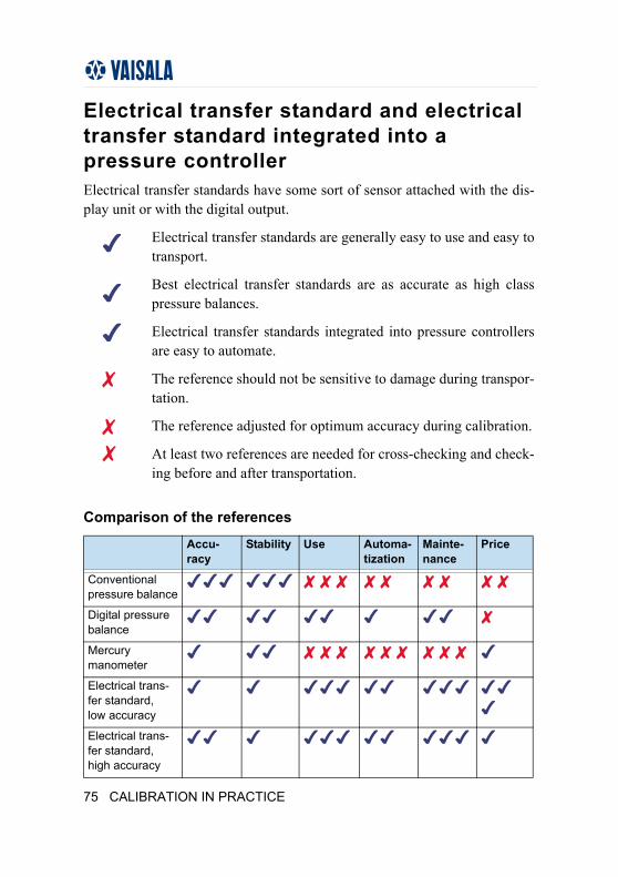
Electrical transfer standard and electrical transfer standard integrated into a pressure controllerElectrical transfer standards have some sort of sensor attached with the dis-play unit or with the digital output.
Electrical transfer standards are generally easy to use and easy to transport.
Best electrical transfer standards are as accurate as high class pressure balances.
Electrical transfer standards integrated into pressure controllers are easy to automate.
The reference should not be sensitive to damage during transpor-tation.
The reference adjusted for optimum accuracy during calibration.
At least two references are needed for cross-checking and check-ing before and after transportation.
Comparison of the references
Accu-racy
Stability Use Automa-tization
Mainte-nance
Price
Conventional pressure balance
Digital pressure balance
Mercury manometer
Electrical trans-fer standard, low accuracy
Electrical trans-fer standard, high accuracy
75 CALIBRATION IN PRACTICE
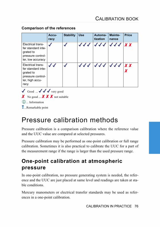
CALIBRATION BOOK
Good ... very good
No good ... not suitable
... Information
...Remarkable point
Pressure calibration methodsPressure calibration is a comparison calibration where the reference value and the UUC value are compared at selected pressures.
Pressure calibration may be performed as one-point calibration or full range calibration. Sometimes it is also practical to calibrate the UUC for a part of the measurement range if the range is larger than the used pressure range.
One-point calibration at atmospheric pressureIn one-point calibration, no pressure generating system is needed, the refer-ence and the UUC are just placed at same level and readings are taken at sta-ble conditions.
Mercury manometers or electrical transfer standards may be used as refer-ences in a one-point calibration.
Electrical trans-fer standard inte-grated to pressure control-ler, low accuracy
Electrical trans-fer standard inte-grated to pressure control-ler, high accu-racy
Comparison of the references
Accu-racy
Stability Use Automa-tization
Mainte-nance
Price
CALIBRATION IN PRACTICE 76
In this case the pressure gradient should be monitored and be sufficiently slow to avoid errors in readings (If the integration times of the reference and the UUC are different the pressure gradient will cause error).
The result of a one-point calibration is usually offset -correction that is added to the reading of the UUC. Some UUC's can be adjusted at the calibration point.
One-point calibrations are useful for barometers and for periodical checking of pressure equipment, in addition to the one-point calibration, the full cali-bration should be carried at regular intervals.
Full calibrationWhen performing a full calibration, a pressure generating system is needed. The reference and the UUC are connected into a closed pressure system at the same level and the readings are taken at adjusted pressure levels.
In full calibration the measurement points (usually from 5 to 11 points) are selected equally spaced from the measurement range. The calibration is per-formed for increasing and degreasing pressures using the same pressure adjustment rate and stabilization times to measure the hysteresis of the UUC.
When changing the pressure the maximum pressure change rate should not be exceeded to avoid damages. Rapid pressure changes also cause adiabatic temperature changes in the system causing long stabilization times.
Pressure balance, mercury manometer or electrical transfer standard may be used as a reference in full calibration.
Pressure can be adjusted using a simple hand pump, vacuum pump and pres-sure supply with adjustment valves or a pressure controller. Sometimes the references may be integrated into the pressure controller.
If a pressure controller is used the calibration can be fully autom-atized.
In this case the pressure system should be leak free and should be tested before each calibration to avoid errors in readings (Leaks may cause large errors and should be corrected before starting the calibration).
77 CALIBRATION IN PRACTICE
CALIBRATION BOOK
The result of full calibrations are usually correction curves from where the correction at measurement points are taken and added to the reading of the UUC. Some UUC's can be adjusted using offset and gain-corrections leaving the unlinearity not corrected while some units can be adjusted for optimum linearity and accu-racy.
Common mistakes
Leak in pressure systemIn case leaks occur in the system significant errors may occur.
How to avoid these errors - make a leak test at highest and lowest measured pressure each time new equipment is added to the sys-tem before starting the calibration. A leak test may be performed by adjusting the pressure, closing system and monitoring the ref-erence reading if the pressure remains. In case leaks occur they should be fixed before calibration.
Why the Reference and UUC should be at the same level?
Hydrostatic pressure effects any pressure system and in case the reference and UUC are at different levels the appropriate correction should be used.
CALIBRATION IN PRACTICE 78
5.VAISALA CALIBRATION SERVICES
In Vaisala calibration is one of our core operations. We have a wide range of calibration services available for customers.
Vaisala calibration services enable you to get the best possible performance from your units.
For further information, please contact Vaisala sales office or service center. Contact information as well as information on our services is available at Vaisala web-site www.vaisala.com.
CALIBRATION SERVICESRelative humidity, dewpoint temperature, barometric pressure and carbon dioxide calibration services are globally available from our regional service centers. We co-operate with world class courier companies to make interna-tional logistics fast and trouble-free.
ACCREDITED CALIBRATION SERVICESAccredited calibrations for measurement instruments are needed when for-mal third party recognition for calibration is required. This recognition is required for instruments used as reference standards, or to meet various demands from different authorities.
Vaisala has accredited calibration services for Vaisala pressure, temperature, dewpoint and humidity instruments. Services are available through regional service centers, and available for both already installed units and together with delivery of new units.
79 VAISALA CALIBRATION SERVICES
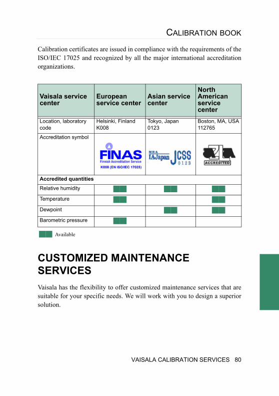
CALIBRATION BOOK
Calibration certificates are issued in compliance with the requirements of the ISO/IEC 17025 and recognized by all the major international accreditation organizations.
Available
CUSTOMIZED MAINTENANCE SERVICESVaisala has the flexibility to offer customized maintenance services that are suitable for your specific needs. We will work with you to design a superior solution.
Vaisala service center
European service center
Asian service center
North American service center
Location, laboratory code
Helsinki, Finland K008
Tokyo, Japan 0123
Boston, MA, USA 112765
Accreditation symbol
Accredited quantities
Relative humidity
Temperature
Dewpoint
Barometric pressure
VAISALA CALIBRATION SERVICES 80
SERVICE CENTER LOCATIONSOn-line technical support
If you need technical support, please contact [email protected]
European Service Center
Vaisala Instruments Service Vanha Nurmijärventie 21 01670 Vantaa FINLAND Phone: +358 9 8949 2658 Fax: +358 9 8949 2295 E-mail: [email protected]
American Service Center
Vaisala Inc. 10-D Gill Street Woburn, MA 01801 USA Phone: +1 888 VAISALA or +1 781 933 4500 Fax: +1 781 933 8029 E-mail: [email protected]
Asian Service Center
Vaisala KK 42 Kagurazaka 6-Chome Shinjuku-ku Tokyo 162-0825 JAPAN Phone: +81 3 3266 9611
81 VAISALA CALIBRATION SERVICES
CALIBRATION BOOK
Fax: +81 3 3266 9610 E-mail: [email protected]
Chinese Service Center
Vaisala China Ltd Floor 2, EAS Building No. 21, Xiao Yun Road, Dongsanhuan Beilu Chaoyang District Beijing 100027 CHINA Phone: +86 10 8526 1199 Fax: +86 10 8526 1155 E-mail: [email protected]
VAISALA CALIBRATION SERVICES 82
APPENDIX A: TERMINOLOGY
ACCREDITATION (LABORATORY)Formal recognition that a laboratory is competent to carry out specific tests or calibrations.
Notes:
1. Accreditation is normally awarded following successful laboratory assessment and is followed by appropriate surveillance.
2. The competence of the laboratory is stated in the accreditation decision, covering: best measurement capability, physical quantity, calibration method and measurement range.
ACCURACY (OF MEASUREMENT)Closeness of the agreement between the result of a measurement and a true value of the measurand.
Notes:
1. "Accuracy" is a qualitative concept.
2. The term precision should not be used for "accuracy".
ADJUSTMENT (OF A MEASUREMENT INSTRUMENT)Operation of bringing a measurement instruments into a state of perfor-mance suitable for its use.
Note:
Adjustment may be automatic, semiautomatic or manual.
83 APPENDIX A: TERMINOLOGY
CALIBRATION BOOK
CALIBRATIONSet of operations that establish, under specified conditions, the relationship between values of quantities indicated by a measurement instrument or mea-surement system, or values represented by a material measure or a reference material, and the corresponding values realized by standards.
Notes:
1. The result of a calibration permits either the assignment of values of measurands to the indications or the determination of corrections with respect to indications.
2. A calibration may also determine other metrological properties such as the effect of influence quantities.
3. The result of a calibration may be recorded in a document, sometimes called a Calibration Certificate or a Calibration Report.
CORRECTIONValue added algebraically to the uncorrected result of a measurement (read-ing) to compensate for systematic error.
Notes:
1. The correction is equal to the negative of the estimated systematic error.
2. Since the systematic error cannot be known perfectly, the compensation cannot be complete.
CORRECTION FACTORNumerical factor by which the uncorrected result of a measurement is multi-plied to compensate for systematic error.
Note:
Since the systematic error cannot be known perfectly, the compensation can-not be complete.
APPENDIX A: TERMINOLOGY 84
INDICATING INSTRUMENT
DIGITAL MEASUREMENT INSTRUMENT
Measurement instrument that provides a digitized output or display.
Note:
This term relates to the form of presentation of the output or display, not to the principle of operation of the instrument.
ANALOG MEASUREMENT INSTRUMENT
Measurement instrument in which the output or display is a continuous func-tion of the measurand or of the input signal.
Note:
This term relates to the form of presentation of the output or display, not to the principle of operation of the instrument.
DISPLAYING
INDICATING DEVICE
Part of a measurement instrument that displays an indication.
Notes:
1. This term may include the device by which the value supplied by a mate-rial measure is displayed or set.
2. An analogue displaying device provides an analogue display: a digital displaying device provides a digital display.
3. A form of presentation of the display either by means of a digital display in which the least significant digit moves continuously, thus permitting interpolation, or by means of a digital display supplemented by a scale and index, is called a semi-digital display.
4. The English term readout device is used as a general descriptor of the means whereby the response of measurement instrument is made avail-able.
85 APPENDIX A: TERMINOLOGY
CALIBRATION BOOK
INDICATING (MEASUREMENT) INSTRUMENTS
Measurement instrument that displays an indication.
Example:
Analog indicating voltmeter, digital frequency meter, micrometer.
Notes:
1. The display may be analogue (continuous or discontinuous) or digital.
2. Values of more than one quantity may be displayed simultaneously.
3. A displaying measurement instrument may also provide a record.
DRIFT (LONG-TERM STABILITY)Slow change of a metrological characteristic of a measurement instrument.
END POINT LINEARITYThe closeness to which the calibration curves can be adjusted to approximate the specified straight line so that the upper and lower range values of both input and output curves coincide.
ERRORResult of a measurement (reading) minus a true value of the measurand.
Note:
Since a true value can not be determined a conventional true value is used.
HYSTERESIS ERRORThe maximum deviation between the two calibration curves of the measured variable as obtained by an upscale going traverse and a downing traverse over the full range and subtracting the value of dead band.
APPENDIX A: TERMINOLOGY 86
LINEARITY ERRORThe absolute value of the maximum deviation between the calibration curve and the specified straight line.
Note:
Linearity error should be qualified. When expressed simply as linearity, it is assumed to be independent linearity error.
RANDOM ERRORResult of a measurement minus the mean that would result from an infinite number of measurements of the same measurand carried out under repeat-ability conditions.
Notes:
1. Random error is equal to error minus systematic error.
2. Because only a finite number of measurements can be made, it is only possible to determine an estimate of random error.
HYSTERESISThe property of a device whereby it gives different output values in relation to its input values depending on the directional sequence in which the input values have been applied.
• Hysteresis is calculated as correction downwards - correction upwards.
INDEPENDENT LINEARITYThe closeness to which the calibration curve can be adjusted to approximate the specified straight line so that the maximum deviation is minimized (best fit).
87 APPENDIX A: TERMINOLOGY
CALIBRATION BOOK
LINEARITYThe closeness to which a calibration curves approximates a specified straight line.
Note:
Linearity should be qualified. When expressed simply as linearity, it is assumed to be independent linearity.
MATERIAL MEASUREDevice intended to reproduce or supply, in a permanent manner during its use, one or more known values of a given quantity.
Example:
Weight, standard electrical resistor or capacitor, gauge block, standard signal generator and reference material.
MEASURANDParticular quantity subjects to measurement.
MEASUREMENT EQUIPMENTMeasurement equipment are equipment used in measurement and they may be actively measurement instruments like measurement instruments, -trans-ducers, -sensors or material measures like weights, standard resistor or capacitors, gauge blocks or reference materials and so on.
APPENDIX A: TERMINOLOGY 88
MEASUREMENT OR MEASUREMENT SYSTEMComplete set of measurement instruments and other equipment assembled to carry out specified measurements.
Example:
The equipment needed in thermometer calibrations that may contain the ref-erence thermometer, reference sensor, calibration bath, ice-point, computer and so on.
Note:
1. The system may include material measures and chemical reagents.
2. A measurement system that is permanently installed is called a measure-ment installation.
MEASUREMENT INSTRUMENTInstrument that is intended to be used to make measurements, alone or in conjunction with supplementary device(s) like sensors.
MEASUREMENT TRANSDUCERDevice that provides an output quantity having a determined relationship to the input quantity.
Example:
Thermocouple, current transformer, strain gauge, pH electrode.
RECORDING DEVICEPart of a measurement instrument that provides record of an indication.
89 APPENDIX A: TERMINOLOGY
CALIBRATION BOOK
RECORDING (MEASUREMENT) INSTRUMENTMeasurement instrument that provides a record of the indication.
Example:
Barograph, chart recorder, datalogger.
Notes:
• The record (display) may be analog (continuous or discontinuous line) or digital.
• Values of more than one quantity may be recorded (displayed) simulta-neously.
• A recording instrument may also display an indication.
REFERENCE, (MEASUREMENT) STANDARD, ETALONMaterial measure, measurement instrument, reference material or measure-ment system intended to define, realize, conserve or reproduce a unit or one or more values of a quantity to serve as a reference.
The references may be named by the function they have like:
International (measurement) standardStandard recognized by an international agreement to serve interna-tionally as the basis for assigning values to other standards of the quantity.
National (measurement) standardStandard recognized by a national decision to serve, in a country, as the basis for assigning values to other standards of the quantity.
Primary standardStandard that is designated or widely acknowledged as having the highest metrological qualities and whose value is accepted without reference to other standards of the same quantity.
APPENDIX A: TERMINOLOGY 90
Secondary standardStandard whose value is assigned by comparison with a primary stan-dard of the same quantity.
Reference standardStandard, generally having the highest metrological quality available at a given location or in a given organization, from which measure-ments made which are derived.
Transfer StandardStandard used as an intermediary to compare standards.
Travelling standardStandard, sometimes of special construction, intended for transport between different locations.
Working standardStandard that is used routinely to calibrate or check material mea-sures, measurement instruments or reference materials.
REPEATABILITY (OF RESULTS OF MEASUREMENTS)Closeness of the agreement between the results of successive measurements of the same measurand carried out under the same conditions of measure-ment.
Notes:
1. These conditions are called repeatability conditions.
2. Repeatability conditions include the same measurement procedure, observer, measurement instrument used under the same conditions and location and repetition is made over a short period of time.
3. Repeatability may be expressed quantitatively in terms of the dispersion characteristics of the results.
91 APPENDIX A: TERMINOLOGY
CALIBRATION BOOK
REPRODUCIBILITY (OF RESULTS OF MEASUREMENTS)Closeness of the agreement between the results of measurements of the same measurand carried out under changed conditions of measurement.
Notes:
1. A valid statement of reproducibility requires specification of the condi-tions changed.
2. The changed conditions may include: principle of measurement, method of measurement, observer, measurement instrument, reference standard, location, conditions of use and time.
3. Reproducibility may be expressed quantitatively in terms of the disper-sion characteristics of the results.
4. Results are here usually understood to be corrected results.
RESPONSE TIMETime interval between the instant when a stimulus is subjected to a specified abrupt change and the instant when the response reaches and remains within specified limits around its final steady value.
SENSORElement of a measurement instrument or measurement chain that is directly affected by the measurand.
Example:
Pt-100 sensor element, humidity sensor.
Note:
In some fields the term "detector" is used for this concept.
APPENDIX A: TERMINOLOGY 92
STABILITY/UNSTABILITYAbility of a measurement instrument to maintain constant its metrological characteristic with time.
•Short-term stability (noise) is usually attributed to time periods less than 24 hours and long-term stability (drift) to longer time periods.
Note:
Where stability with respect to a quantity other than time is considered, this should be stated explicitly.
SYSTEMATIC ERRORMean that would result from an infinite number of measurements of the same measurand carried out under repeatability conditions minus a true value of the measurand.
Notes:
1. Systematic error is equal to error minus random error.
2. Like true value, systematic error and its causes cannot be completely known.
TRACEABILITY (OF MEASUREMENT)Property of the result of a measurement or the value of a standard whereby it can be related to stated references, usually national or international stan-dards, through an unbroken chain of comparisons all having stated uncer-tainties.
Notes:
1. The concept is often expressed by the adjective traceable.
2. The unbroken chain of comparisons is called a traceability chain.
93 APPENDIX A: TERMINOLOGY
CALIBRATION BOOK
UNCERTAINTY (OF MEASUREMENT)Parameter associated with the result of a measurement, which characterizes the dispersion of the values that could reasonably be attributed to the mea-surand.
Notes:
1. The parameter may be, for example, a standard deviation (or a given multiple of it), or the half-width of an interval having a stated level of confidence.
2. Uncertainty of measurement comprises, in general, many components. Some of these components may be evaluated from the statistical distribu-tion of the results of series of measurements and can be characterized by experimental standard deviations. The other components, which can also be characterized by standard deviations, are evaluated from assumed probability distributions based on experience or other information.
3. It is understood that the result of the measurement is the best estimate of the value of the measurand, and that all components of uncertainty, including those arising from systematic effects, such as components associated with corrections and reference standards, contribute to the dis-persion.
This definition is that of the "Guide to the expression of uncertainty in mea-surement" in which its rationale is detailed (see, APPENDIX C).
APPENDIX A: TERMINOLOGY 94
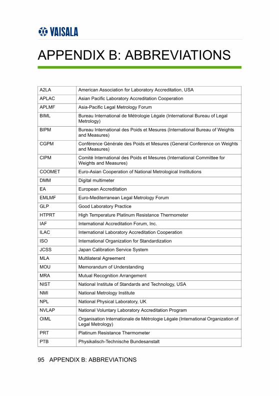
APPENDIX B: ABBREVIATIONS
A2LA American Association for Laboratory Accreditation, USA
APLAC Asian Pacific Laboratory Accreditation Cooperation
APLMF Asia-Pacific Legal Metrology Forum
BIML Bureau International de Métrologie Légale (International Bureau of Legal Metrology)
BIPM Bureau International des Poids et Mesures (International Bureau of Weights and Measures)
CGPM Conférence Générale des Poids et Mesures (General Conference on Weights and Measures)
CIPM Comité International des Poids et Mesures (International Committee for Weights and Measures)
COOMET Euro-Asian Cooperation of National Metrological Institutions
DMM Digital multimeter
EA European Accreditation
EMLMF Euro-Mediterranean Legal Metrology Forum
GLP Good Laboratory Practice
HTPRT High Temperature Platinum Resistance Thermometer
IAF International Accreditation Forum, Inc.
ILAC International Laboratory Accreditation Cooperation
ISO International Organization for Standardization
JCSS Japan Calibration Service System
MLA Multilateral Agreement
MOU Memorandum of Understanding
MRA Mutual Recognition Arrangement
NIST National Institute of Standards and Technology, USA
NMI National Metrology Institute
NPL National Physical Laboratory, UK
NVLAP National Voluntary Laboratory Accreditation Program
OIML Organisation Internationale de Métrologie Légale (International Organization of Legal Metrology)
PRT Platinum Resistance Thermometer
PTB Physikalisch-Technische Bundesanstalt
95 APPENDIX B: ABBREVIATIONS
CALIBRATION BOOK
QMS Quality Management Standard
SADCMEL Southern African Development Community
SI Système International d'Unités (International System of Units)
SIM Sistema Interamericano de Metrologia
SPRT Standard Platinum Resistance Thermometer
UUC Unit Under Calibration
UUT Unit Under Test
WELMEC European Cooperation in Legal Metrology
APPENDIX B: ABBREVIATIONS 96
APPENDIX C: UNCERTAINTY CALCULATION
Uncertainty may be calculated in several ways. The reliability of the given uncertainty often depends more on the professionalism of the person per-forming the calculation than on the calculation method used.
Two common mistakes in uncertainty calculations are:
•Giving only the calibration uncertainty of the reference equipment and "forgetting" the long-term stability of the reference and uncer-tainties caused by the calibration process and unit under calibration.
•"Forgetting" some uncertainty components to get "suitable" uncer-tainty values.
It is almost impossible to evaluate the reliability of the given uncertainty unless the calibration is performed by an accredited calibration laboratory. The uncertainty estimations of accredited calibration laboratories are always inspected by qualified technical specialists.
In the following some practical examples are given for people who are developing calibration systems and uncertainty estimations or evaluating suppliers calibration systems.
The examples given in this appendix are made according to EA-4/02 "Expression of the Uncertainty of Measurement in Calibration".
97 APPENDIX C: UNCERTAINTY CALCULATION
CALIBRATION BOOK
General• The statement of the result of a measurement is complete only if it con-
tains both the values attributed to the measurand and the uncertainty of measurement associated with that value.
• The uncertainty of measurement is a parameter, associated with the result of a measurement, which characterizes the dispersion of the values that could reasonably be attributed to the measurand.
Uncertainty is given using the same unit and precision as the measurement result.
EXAMPLE: 75.5 %RH ± 2.0 %RH, (k = 2)
The statement of the result of a measurement is complete only if it contains both the values attributed to the measurand and the uncertainty of measure-ment associated with that value.
Uncertainty typesThere are two different methods on evaluating uncertainty:
1. Type A method is based on statistical methods.
2. Type B method is based on other methods.
APPENDIX C: UNCERTAINTY CALCULATION 98
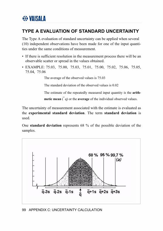
TYPE A EVALUATION OF STANDARD UNCERTAINTYThe Type A evaluation of standard uncertainty can be applied when several (10) independent observations have been made for one of the input quanti-ties under the same conditions of measurement.
• If there is sufficient resolution in the measurement process there will be an observable scatter or spread in the values obtained.
• EXAMPLE: 75.03, 75.00, 75.03, 75.01, 75.00, 75.02, 75.06, 75.05, 75.04, 75.06
The average of the observed values is 75.03
The standard deviation of the observed values is 0.02
The estimate of the repeatedly measured input quantity is the arith-
metic mean ( \q) or the average of the individual observed values.
The uncertainty of measurement associated with the estimate is evaluated as the experimental standard deviation. The term standard deviation is used.
One standard deviation represents 68 % of the possible deviation of the samples.
99 APPENDIX C: UNCERTAINTY CALCULATION
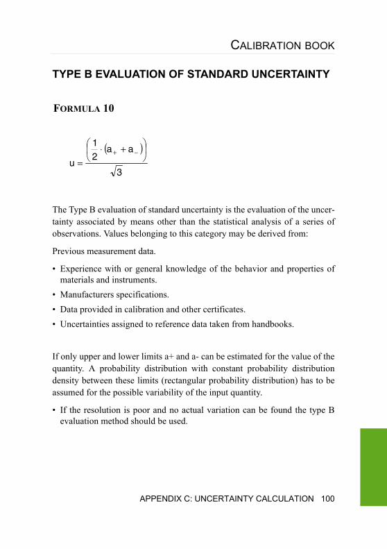
CALIBRATION BOOK
TYPE B EVALUATION OF STANDARD UNCERTAINTY
The Type B evaluation of standard uncertainty is the evaluation of the uncer-tainty associated by means other than the statistical analysis of a series of observations. Values belonging to this category may be derived from:
Previous measurement data.
• Experience with or general knowledge of the behavior and properties of materials and instruments.
• Manufacturers specifications.• Data provided in calibration and other certificates.• Uncertainties assigned to reference data taken from handbooks.
If only upper and lower limits a+ and a- can be estimated for the value of the quantity. A probability distribution with constant probability distribution density between these limits (rectangular probability distribution) has to be assumed for the possible variability of the input quantity.
• If the resolution is poor and no actual variation can be found the type B evaluation method should be used.
( )
3
aa21
u⎟⎠
⎞⎜⎝
⎛ +⋅=
−+
FORMULA 10
APPENDIX C: UNCERTAINTY CALCULATION 100
EXAMPLE 1: 75.0, 75.0, 75.0, 75.0, 75.0, 75.0, 75.1, 75.1, 75.0, 75.1
•The average of the observed values is 75.03
•The standard deviation of the observed values is 0.05
•In this case the standard deviation would give acceptable estimate for the uncertainty. However, in a case where the measured values are all the same, the type B should be used.
EXAMPLE 2: 75.0, 75.0, 75.0, 75.0, 75.0, 75.0, 75.0, 75.0, 75.0, 75.0
•The average of the observed values is 75.00
•The standard deviation of the observed values is 0.00 that is of course not true as we know the measured values are somewhere between 74.95 and 75.05 and that why the type B should be used. In this case the calculation would be:
• In this case the minimum value for uncertainty would be 0.023.
( )023.0
3
05.0
3
)05.0(05.021
u ==⎟⎠
⎞⎜⎝
⎛ −+⋅=
FORMULA 11
101 APPENDIX C: UNCERTAINTY CALCULATION
CALIBRATION BOOK
Typical uncertainty factorsTypically uncertainty is composed from the uncertainties of the reference, calibration and unit under calibration. Refer to the following terms below:
Reference:Calibration uncertainty from certificate
Long-term stability
Short-term stability + effect of environmental conditions
Resolution, linearity, hysteresis
Calibration:Deviation of the measurement results
Effect of environmental conditions
Unit under Calibration:Resolution
Short-term stability + effect of environmental conditions
Hysteresis
Linearity
Repeatability
APPENDIX C: UNCERTAINTY CALCULATION 102
Examples of determining uncertainty factors
Long-term stability of the reference equipmentThe reference must have at least two calibrations before the long-term stabil-ity can be determined.
For example, the reference resistor was first calibrated at a 6 month interval. To get the first uncertainty estimation, the following will be calculated:
• 6 month drift was converted to 12 month drift:• 5.4 ppm / Time between calibrations · 1 year = 10.4 ppm / yearThis is type B uncertainty and can be converted to a standard uncertainty by dividing it by the square root of three
In table below the uncertainties are calculated from the actual measurement data:
Long-term uncertainty of the reference resistor Calibration Time
[years]Time between calibrations [years]
Observed drift [ppm]
Drift/year [ppm]
Uncertainty [ppm]
1 0.0 0.0
2 0.5 0.52 5.4 10.4 ±6.0
3 1.6 1.12 4.2 3.8 ±2.2
4 2.8 1.15 0.8 0.7 ±0.4
5 3.8 1.02 -1.1 -1.1 ±0.6
6 4.6 0.75 2.8 3.8 ±2.2
7 5.6 1.09 0.2 0.2 ±0.1
10.4 ppm / 3 = 6.0 ppm
FORMULA 12
103 APPENDIX C: UNCERTAINTY CALCULATION
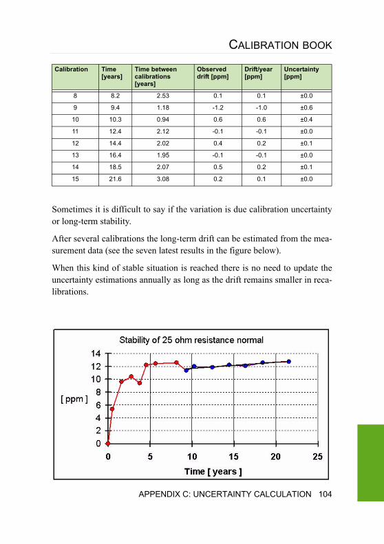
CALIBRATION BOOK
Sometimes it is difficult to say if the variation is due calibration uncertainty or long-term stability.
After several calibrations the long-term drift can be estimated from the mea-surement data (see the seven latest results in the figure below).
When this kind of stable situation is reached there is no need to update the uncertainty estimations annually as long as the drift remains smaller in reca-librations.
8 8.2 2.53 0.1 0.1 ±0.0
9 9.4 1.18 -1.2 -1.0 ±0.6
10 10.3 0.94 0.6 0.6 ±0.4
11 12.4 2.12 -0.1 -0.1 ±0.0
12 14.4 2.02 0.4 0.2 ±0.1
13 16.4 1.95 -0.1 -0.1 ±0.0
14 18.5 2.07 0.5 0.2 ±0.1
15 21.6 3.08 0.2 0.1 ±0.0
Calibration Time [years]
Time between calibrations [years]
Observed drift [ppm]
Drift/year [ppm]
Uncertainty [ppm]
APPENDIX C: UNCERTAINTY CALCULATION 104
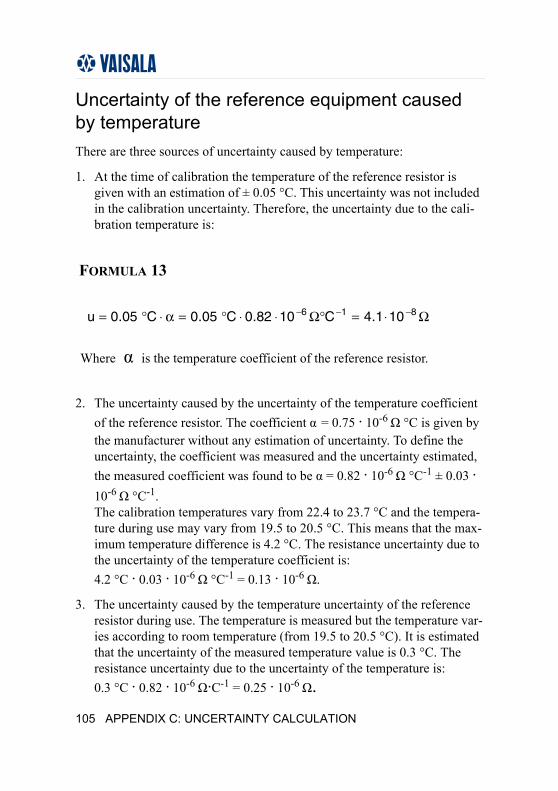
Uncertainty of the reference equipment caused by temperatureThere are three sources of uncertainty caused by temperature:
1. At the time of calibration the temperature of the reference resistor is given with an estimation of ± 0.05 °C. This uncertainty was not included in the calibration uncertainty. Therefore, the uncertainty due to the cali-bration temperature is:
2. The uncertainty caused by the uncertainty of the temperature coefficient of the reference resistor. The coefficient α = 0.75 · 10-6 Ω °C is given by the manufacturer without any estimation of uncertainty. To define the uncertainty, the coefficient was measured and the uncertainty estimated, the measured coefficient was found to be α = 0.82 · 10-6 Ω °C-1 ± 0.03 · 10-6 Ω °C-1. The calibration temperatures vary from 22.4 to 23.7 °C and the tempera-ture during use may vary from 19.5 to 20.5 °C. This means that the max-imum temperature difference is 4.2 °C. The resistance uncertainty due to the uncertainty of the temperature coefficient is: 4.2 °C · 0.03 · 10-6 Ω °C-1 = 0.13 · 10-6 Ω.
3. The uncertainty caused by the temperature uncertainty of the reference resistor during use. The temperature is measured but the temperature var-ies according to room temperature (from 19.5 to 20.5 °C). It is estimated that the uncertainty of the measured temperature value is 0.3 °C. The resistance uncertainty due to the uncertainty of the temperature is: 0.3 °C · 0.82 · 10-6 Ω·C-1 = 0.25 · 10-6 Ω.
Ω⋅=°Ω⋅⋅°=α⋅°= −−− 816 101.4C1082.0C05.0C05.0u
Where α is the temperature coefficient of the reference resistor.
FORMULA 13
105 APPENDIX C: UNCERTAINTY CALCULATION
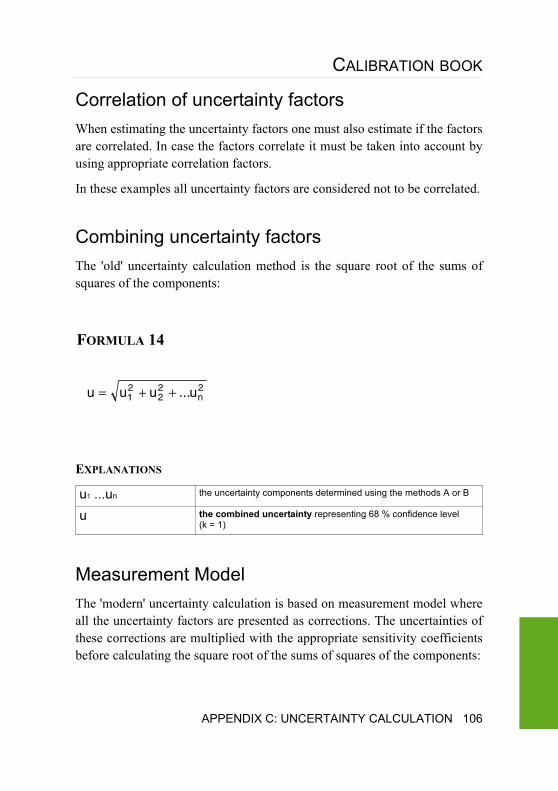
CALIBRATION BOOK
Correlation of uncertainty factorsWhen estimating the uncertainty factors one must also estimate if the factors are correlated. In case the factors correlate it must be taken into account by using appropriate correlation factors.
In these examples all uncertainty factors are considered not to be correlated.
Combining uncertainty factorsThe 'old' uncertainty calculation method is the square root of the sums of squares of the components:
EXPLANATIONS
Measurement ModelThe 'modern' uncertainty calculation is based on measurement model where all the uncertainty factors are presented as corrections. The uncertainties of these corrections are multiplied with the appropriate sensitivity coefficients before calculating the square root of the sums of squares of the components:
u1 ...un the uncertainty components determined using the methods A or B
u the combined uncertainty representing 68 % confidence level (k = 1)
2n
22
21 u...uuu ++=
FORMULA 14
APPENDIX C: UNCERTAINTY CALCULATION 106
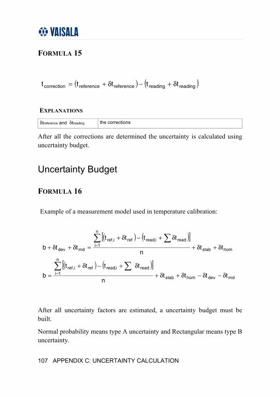
EXPLANATIONS
After all the corrections are determined the uncertainty is calculated using uncertainty budget.
Uncertainty Budget
After all uncertainty factors are estimated, a uncertainty budget must be built.
Normal probability means type A uncertainty and Rectangular means type B uncertainty.
δtreference and δtreading the corrections
( ) ( )readingreadingreferencereferencecorrection ttttt δ+−δ+=
FORMULA 15
FORMULA 16
Example of a measurement model used in temperature calibration:
( ) ( )[ ]
( ) ( )[ ]rnddevhomstab
n
1ireadi,readrefi,ref
homstab
n
1ireadi,readrefi,ref
rnddev
ttttn
tttt
b
ttn
tttt
ttb
δ−δ−δ+δ+δ+−δ+
=
δ+δ+δ+−δ+
=δ+δ+
∑ ∑
∑ ∑
=
=
107 APPENDIX C: UNCERTAINTY CALCULATION
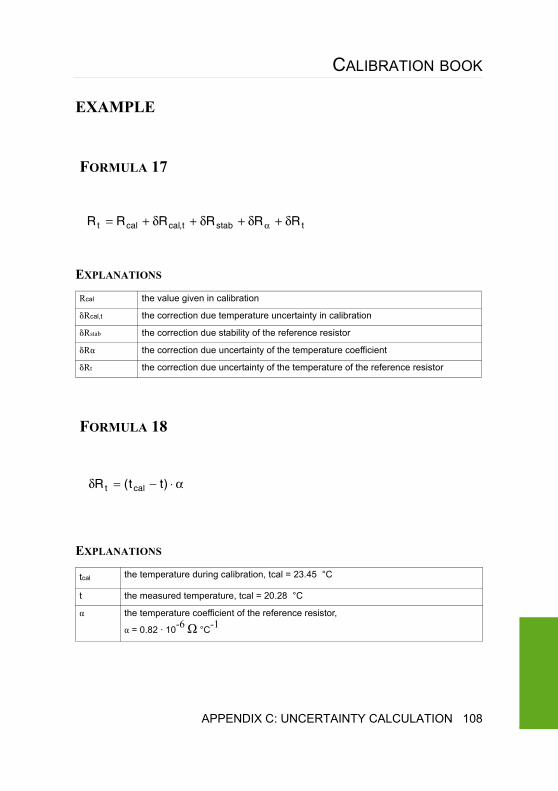
CALIBRATION BOOK
EXAMPLE
EXPLANATIONS
EXPLANATIONS
Rcal the value given in calibration
δRcal,t the correction due temperature uncertainty in calibration
δRstab the correction due stability of the reference resistor
δRα the correction due uncertainty of the temperature coefficient
δRt the correction due uncertainty of the temperature of the reference resistor
tcal the temperature during calibration, tcal = 23.45 °C
t the measured temperature, tcal = 20.28 °C
α the temperature coefficient of the reference resistor,
α = 0.82 · 10-6 Ω °C-1
tstabt,calcalt RRRRRR δ+δ+δ+δ+= α
FORMULA 17
α⋅−=δ )tt(R calt
FORMULA 18
APPENDIX C: UNCERTAINTY CALCULATION 108
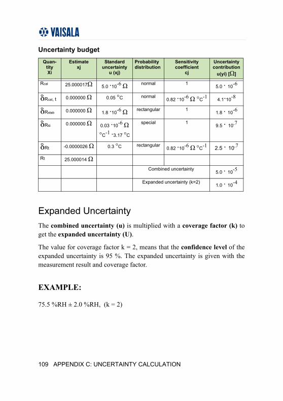
Uncertainty budget
Expanded UncertaintyThe combined uncertainty (u) is multiplied with a coverage factor (k) to get the expanded uncertainty (U).
The value for coverage factor k = 2, means that the confidence level of the expanded uncertainty is 95 %. The expanded uncertainty is given with the measurement result and coverage factor.
EXAMPLE:
75.5 %RH ± 2.0 %RH, (k = 2)
Quan-tityXi
Estimatexj
Standard uncertainty
u (xj)
Probability distribution
Sensitivitycoefficient
cj
Uncertaintycontribution
u(yi) [Ω]
Rcal 25.000017Ω 5.0 ·10-6 Ω normal 1 5.0 · 10-6
δRcal, t 0.000000 Ω 0.05 °C normal0.82 ·10-6 Ω °C-1 4.1·10-8
δRstab 0.000000 Ω 1.8 ·10-6 Ω rectangular 11.8 · 10-6
δRα 0.000000 Ω 0.03 ·10-6 Ω °C-1 ·3.17 °C
special 19.5 · 10-7
δRt -0.0000026 Ω 0.3 °C rectangular0.82 ·10-6 Ω °C-1 2.5 · 10-7
Rt 25.000014 Ω
Combined uncertainty5.0 · 10-5
Expanded uncertainty (k=2) 1.0 · 10-4
109 APPENDIX C: UNCERTAINTY CALCULATION
CALIBRATION BOOK
Presenting UncertaintyNo rounding is made in sub-calculations. The uncertainty is usually given with two significant digits after the decimal point:
1000.22 hPa ± 0.15 hPa instead of 1000.22 hPa ± 0.15127 hPa.
The expanded uncertainty may be rounded downwards if the rounded amount is less than 5 % of the uncertainty value. All other values should be rounded upwards.
± 0.106 hPa should be rounded to ± 0.2 hPa instead of ± 0.1 hPa, which as 5 % of 0.106 hPa is 0.0053 hPa and if rounded to ± 0.1 hPa the rounded part 0.006 > 0.0053 hPa.
APPENDIX C: UNCERTAINTY CALCULATION 110
REFERENCES
1. Japan Industrial Standard / JIS Z 8806. 2001
2. Japan Industrial Standard / JIS B 7920. 2000
3. Humidity Measurement by Sensor Research Society
4. Humidity Measurement & Sensor Manual / October, 1989
5. Japan Testing Machinery Association
6. Standardization of Measurement & Control Technology of Environmen-tal Testing Machinery / 1994
7. A guide to the measurement of humidity / ISBN 0-904457-24-9, NPL, 1996
8. Expression of the Uncertainty of Measurement in Calibration / EA-4/02
9. International Vocabulary of Basic and General Terms in Metrology / ISO 1993
10. Guide to Meteorological Instruments and Methods of Observation. / WMO No. 8. World Meteorological
11. Secretariat of the World Meteorological Organization / Geneva, Switzer-land, 1983 Fifth edition.
12. International Organization for Standardization (http://www.iso.org/iso/en/ISOOnline.frontpage) / accessed on 20.03.2006
13. Bureau International des Poids et Mesures (http://www.bipm.fr/en/home/) / accessed on 17.03.2006
111 REFERENCES


www.vaisala.com