valhall field - start - · pdf file– valhall field primary depletion, ... standard nscc...
TRANSCRIPT
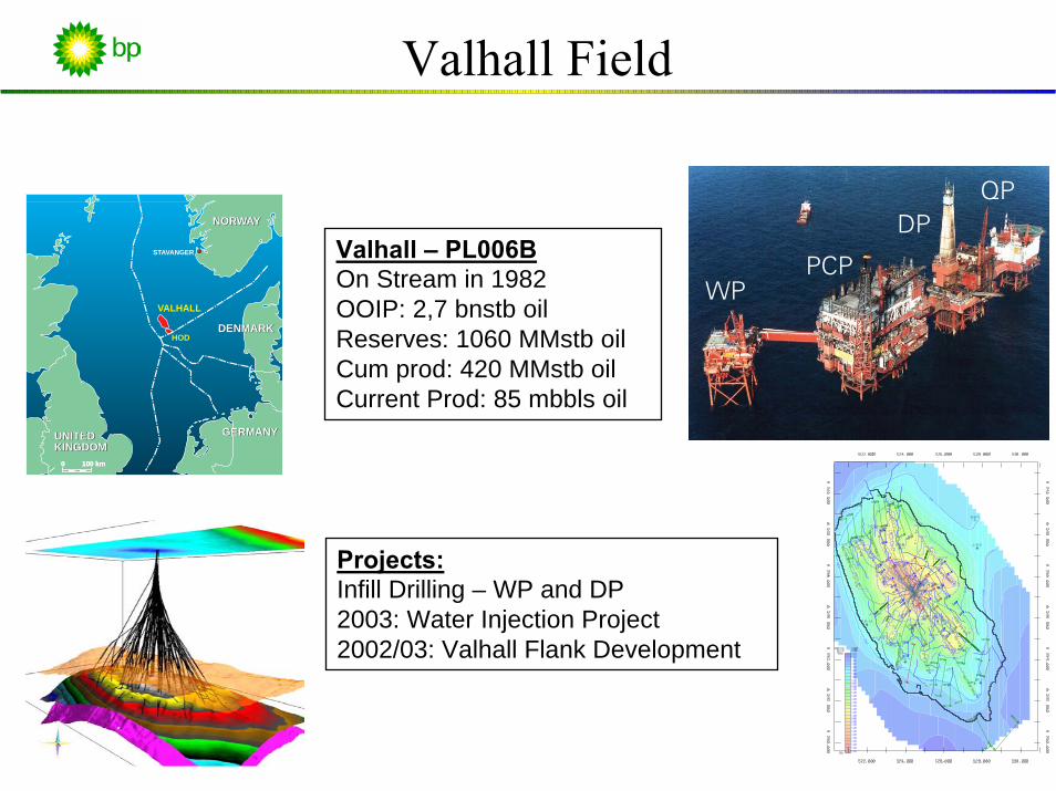
Valhall Field
PCP
DPQP
WPVALHALL
STAVANGER
0 100 km
UNITEDKINGDOM
NORWAY
GERMANY
DENMARK
UNITEDKINGDOM
GERMANY
DENMARK
NORWAY
0 100 km
HOD
Valhall – PL006BOn Stream in 1982OOIP: 2,7 bnstb oilReserves: 1060 MMstb oilCum prod: 420 MMstb oilCurrent Prod: 85 mbbls oil
Projects:Infill Drilling – WP and DP2003: Water Injection Project2002/03: Valhall Flank Development

Valhall Depletion Strategy
• Short term (2000 - 2003):– Valhall field primary depletion, Tor and Lower Hod formation - drill up WP
slots and ‘repair’ DP slots.
• Medium term (2003 - 2006):– Secondary recovery: Phase 1 Waterflood Valhall Tor formation– Develop Valhall flanks - primary depletion– Appraise Flank upside and Area prospects– Continued infill drilling / ’repair’ wells
• Long term (2006 ->):– Optimize Valhall Waterflood– Opportunities for Valhall EOR– Continued infill drilling / ’repair’ wells– Re-development ?
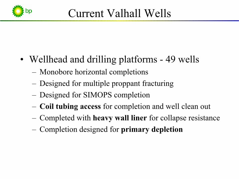
Current Valhall Wells
• Wellhead and drilling platforms - 49 wells– Monobore horizontal completions– Designed for multiple proppant fracturing– Designed for SIMOPS completion– Coil tubing access for completion and well clean out– Completed with heavy wall liner for collapse resistance– Completion designed for primary depletion

Current Valhall Wells
7" x 4 1/2" Packer
4 1/2" DHPG
5 1/2" TRSCSSV
5 1/2" 20# Tubing
6 5/8" 66# Liner
9 5/8" 53.5# csg
Producer Well CompletionCurrent Design
Tubing Hanger
Hydraulic LineDHPG Line
Control Line Color Code
3.750" Landing Nipple
5 1/2" ASV
4 1/2" 12.6# Tubing
x-over 5 1/2" x 4 1/2"
4 1/2" Gas Lift Mandrel
4 1/2" Mule Shoe
13 3/8" 72# csg

Challenges Ahead - Waterflood
• Possible flow anisotropy and direction − Risk of premature water breakthrough along faults/fractures
• Water injectivity − Effect of pressure/temperature induced fracturing
• Effect of Water weakening of the Chalk• Scaling• Water management• Chalk influxes
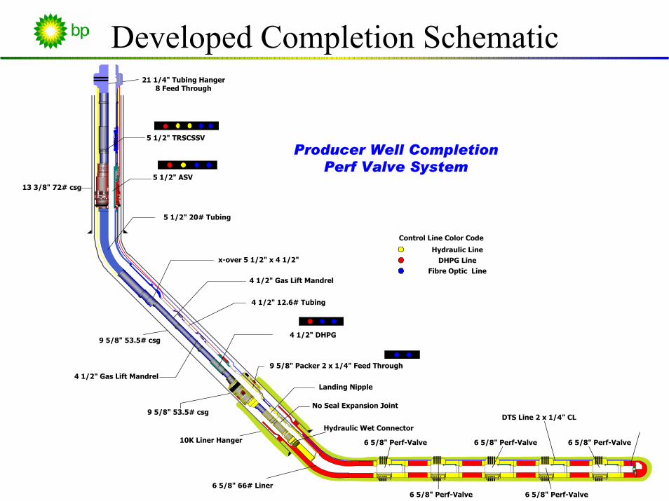
Developed Completion Schematic
5 1/2" TRSCSSV
5 1/2" 20# Tubing
6 5/8" 66# Liner
9 5/8" 53.5# csg
Producer Well CompletionPerf Valve System
21 1/4" Tubing Hanger8 Feed Through
Hydraulic LineDHPG Line
Control Line Color Code
5 1/2" ASV
4 1/2" 12.6# Tubing
x-over 5 1/2" x 4 1/2"
4 1/2" Gas Lift Mandrel
4 1/2" Gas Lift Mandrel
13 3/8" 72# csg
9 5/8" Packer 2 x 1/4" Feed Through
Landing Nipple
No Seal Expansion Joint
Hydraulic Wet Connector
6 5/8" Perf-Valve 6 5/8" Perf-Valve
6 5/8" Perf-Valve
6 5/8" Perf-Valve
6 5/8" Perf-Valve
DTS Line 2 x 1/4" CL
10K Liner Hanger
9 5/8" 53.5# csg
4 1/2" DHPG
Fibre Optic Line

Development Challenges
Cementing
Barrier issues
Deployment
Control lineintegrity
Collapseresistance
Packer performance
Alignment
ResourcesLinerrotation
Groove inliner
Bu
ProtectorsCentalizers
dgets
Time Pipeconnections
Functional Requirement
SystemRequirement
Liner Installation UpperCompletion Installation
Proppant Stimulation
Fiber Optic Installation
Production Well Intervention Contingent Perforating Re-Stimulation Workover
Acid Stimulation
Mod
es
a. -----b. -----c. -----d. -----e. -----f. -----
a. -----b. -----c. -----d. -----e. -----f. -----
a. -----b. -----c. -----d. -----e. -----f. -----
a. -----b. -----c. -----d. -----e. -----f. -----
a. -----b. -----c. -----d. -----e. -----f. -----
a. -----b. -----c. -----d. -----e. -----f. -----
a. -----b. -----c. -----d. -----e. -----f. -----
a. -----b. -----c. -----d. -----e. -----f. -----
a. -----b. -----c. -----d. -----e. -----f. -----
a. -----b. -----c. -----d. -----e. -----f. -----
Env
ironm
ent
Func
tiona
l R
equi
rem
ent
1. -----2. -----3. -----4. -----5. -----6. -----
1. -----2. -----3. -----4. -----5. -----6. -----
1. -----2. -----3. -----4. -----5. -----6. -----
1. -----2. -----3. -----4. -----5. -----6. -----
1. -----2. -----3. -----4. -----5. -----6. -----
1. -----2. -----3. -----4. -----5. -----6. -----
1. -----2. -----3. -----4. -----5. -----6. -----
1. -----2. -----3. -----4. -----5. -----6. -----
1. -----2. -----3. -----4. -----5. -----6. -----
1. -----2. -----3. -----4. -----5. -----6. -----

Joint Development Project
Q4/01
Q1/02
Q2/02
Q3/02
Q4/02
Q1/03
Q2/03
Time
Task
Q4/01
Q1/02
Q2/02
Q3/02
Q4/02
Q1/03
Q2/03
Prestudy/work
Agreement15/5 '02
PV Redesign
Packer Design
Expansion Joint
Connection &flatpack design
Stack-up Test10-14/3 ’03

DTS Completion Schematic
6 5/8" 66# Liner
9 5/8" 53.5# csg
Upper Completion Parts
Hydraulic Wet Connector
Lower Completion Parts
Turnaround subPerf ValvesPerf Valve DTS Lines
Feed Through Packer
Lower Completion Components:– Perf Valve– Liner Hanger System– Timed Connection-slotted pipe– Casing Receptacle
Upper Completion Components:– Wet Connect– Expansion Joint– Retrievable Production Packer

Lower Completion: Perf Valve
Feature Benefit:
Multiple Piston: No perforation
Proppant Frac Resistant
Adjustable flow area
Contaminate cement
Sliding Sleeve: Selective production/injection
Maintain Well Integrity
Liner Mounted: Cemented in place
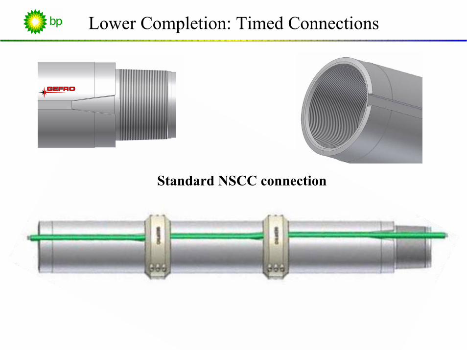
Lower Completion: Timed Connections
Standard NSCC connection
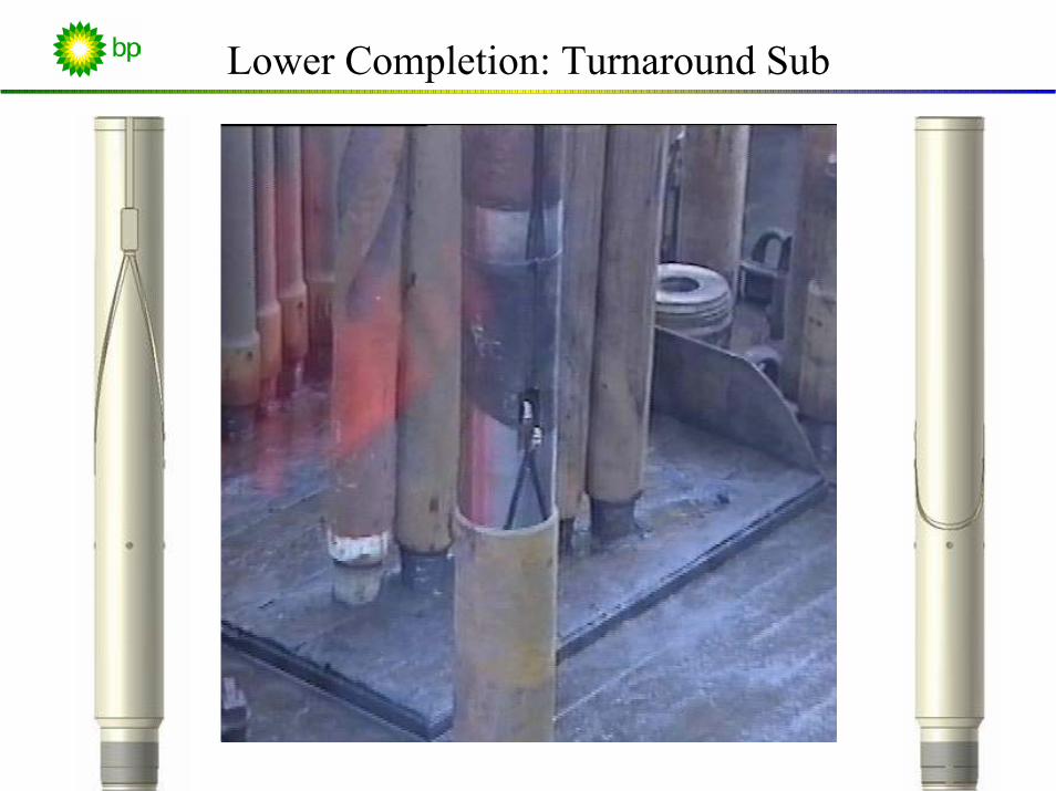
Lower Completion: Turnaround Sub

Lower Completion: Casing Receptacle
• Liner mounted part of Wet Connect
• Provides the reconnect point for the 1/4” control lines
• Contains the male half of the hydraulic connector.
• Allows the control line to pass from inside the liner to outside.
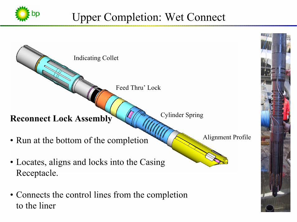
Upper Completion: Wet Connect
Reconnect Lock Assembly
• Run at the bottom of the completion
• Locates, aligns and locks into the Casing Receptacle.
• Connects the control lines from the completion to the liner
Indicating Collet
Feed Thru’ Lock
Cylinder Spring
Alignment Profile

Upper Completion: Expansion Joint
Expansion Joint
• Run between packer and wet connect
• Rotational locked
• 2 meter stroke
• 2 ea ¼” control line by-pass

Upper Completion: Feed Through Packer
• Retrievable Packer, 7.5k Rated• Up to 7 feed troughs (1/4” lines)
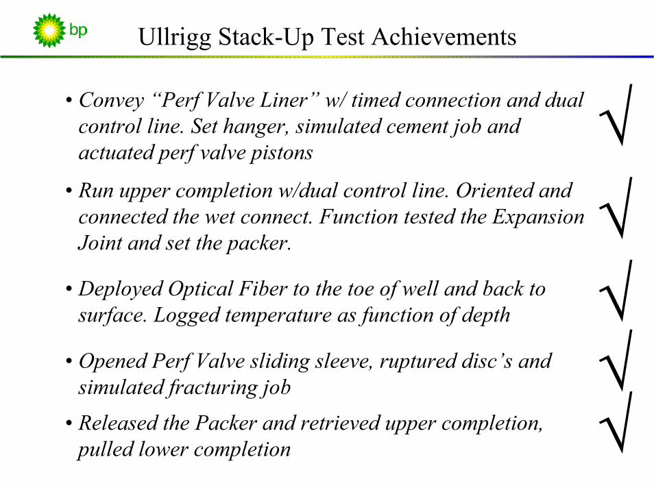
Ullrigg Stack-Up Test Achievements
√• Convey “Perf Valve Liner” w/ timed connection and dual control line. Set hanger, simulated cement job and actuated perf valve pistons
• Run upper completion w/dual control line. Oriented and connected the wet connect. Function tested the Expansion Joint and set the packer.
√√
• Deployed Optical Fiber to the toe of well and back to surface. Logged temperature as function of depth
√• Opened Perf Valve sliding sleeve, ruptured disc’s and simulated fracturing job
å Released the Packer and retrieved upper completion, pulled lower completion

System Benefits
Perf Valve: DTS:• Initial Installation:
− Allows DTS deployment
•Stimulation− Increased Proppant size− Eliminate Perforating− Selective stimulation
•Zonal Isolation−Reduce Chalk influxes−Water shut-off−Remedial work−Selective production
•Flow into liner− Production− Water breakthrough− Gas lift monitoring
• Flow out of liner− Injection− Stimulation− Scale squeezes
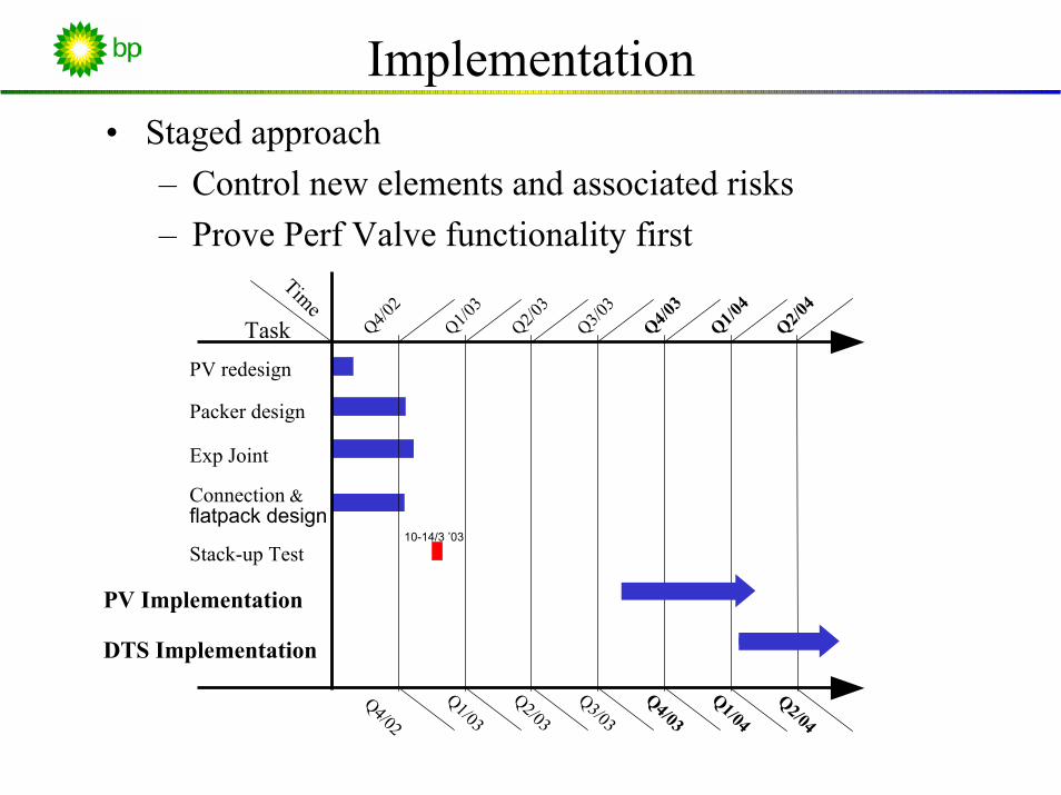
Implementation• Staged approach
– Control new elements and associated risks– Prove Perf Valve functionality first
PV redesign
Packer design
Exp Joint
Connection &flatpack design
Stack-up Test10-14/3 ’03
Q4/02
Q1/03
Q2/03
Q3/03
Q4/03
Q1/04
Q2/04
Time
Task
Q4/02
Q1/03
Q2/03
Q3/03
Q4/03
Q1/04
Q2/04
DTS Implementation
PV Implementation