valliammai engineering college … semester/ge8261-engineering...department of mechanical...
TRANSCRIPT
ENGINEERING PRACTICES LAB_ ______________________________________1
VALLIAMMAI ENGINEERING COLLEGE
SRM Nagar, Kattankulathur-603 203.
DEPARTMENT OF MECHANICAL ENGINEERING
ENGINEERING PRACTICES LAB
(GE 8261)
LABORATORY MANUAL
(REGULATION – 2017)
ACADEMIC YEAR 2017-2018
ENGINEERING PRACTICES LAB_ ______________________________________2
EPL – MECHANICAL

ENGINEERING PRACTICES LAB_ ______________________________________3
MECHANICAL ENGINEERING PRACTICE
Welding:
(a) Preparation of arc welding of butt joints, lap joints and tee joints.
(b) Gas welding practice
Basic Machining:
(a) Simple Turning and Taper turning
(b) Drilling Practice
Sheet Metal Work:
(a) Forming & Bending:
(b) Model making – Trays, funnels, etc.
(c) Different type of joints.
Machine assembly practice:
(a) Study of centrifugal pump
(b) Study of air conditioner
Demonstration on:
(a) Smithy operations, upsetting, swaging, setting down and bending. Example –
Exercise – Production of hexagonal headed bolt.17
(b) Foundry operations like mould preparation for gear and step cone pulley.
(c) Fitting – Exercises – Preparation of square fitting and vee – fitting models.
Equipment Required
1. Arc welding transformer with cables and holders 5 Nos.
2. Welding booth with exhaust facility 5 Nos.
3. Welding accessories like welding shield, chipping hammer,
Wire brush, etc. 5 Sets.
4. Oxygen and acetylene gas cylinders, blow pipe and other
Welding outfit. 2 Nos.
5. Centre lathe 2 Nos.
6. Hearth furnace, anvil and smithy tools 2 Sets.
7. Moulding table, foundry tools 2 Sets.
8. Power Tool: Angle Grinder 2 Nos
9. Study-purpose items: centrifugal pump, air-conditioner One each.
ENGINEERING PRACTICES LAB_ ______________________________________4
LIST OF EXPERIMENTS
CONTENT Page No.
WELDING 4
1. Butt Joint 18
2. Lap Joint 21
3. T-Joint 24
LATHE 26
1. Turning, Facing and Chamfering 38
2. Taper turning 41
3. Drilling and Tapping 44
SHEET METAL 55
1. Cone Making 63
2. Tray Making 66
TOPIC BEYOND SYLLABUS 71
ENGINEERING PRACTICES LAB_ ______________________________________5

ENGINEERING PRACTICES LAB_ ______________________________________6
WELDING
Welding is a fabrication process that joins materials, usually metals or thermoplastics, by
causing coalescence. This is often done by melting the work pieces and adding a filler material to form
a pool of molten material (the weld puddle) that cools to become a strong joint, with pressure
sometimes used in conjunction with heat, or by itself, to produce the weld. This is in contrast with
soldering and brazing, which involve melting a lower-melting-point material between the work pieces
to form a bond between them, without melting the work pieces.
Many different energy sources can be used for welding, including a gas flame, an electric arc, a
laser, an electron beam, friction, and ultrasound. While often an industrial process, welding can be
done in many different environments, including open air, underwater and in space. Regardless of
location, however, welding remains dangerous, and precautions must be taken to avoid burns, electric
shock, eye damage, poisonous fumes, and overexposure to ultraviolet light.
TYPES OF WELDING
Arc Welding
Arc welding is a process utilizing the concentrated heat of an electric arc to join metal by
fusion of the parent metal and the addition of metal to joint usually provided by a consumable
electrode. Either direct or alternating current may be used for the arc, depending upon the material to
be welded and the electrode used.
Gas Welding
It is a metal joining process in which the ends of pieces to be joined are heated at their
interface by producing coalescence with one or more gas flames (such as oxygen and acetylene), with
or without the use of a filler metal.
Welding Safety
Welding hazards pose an unusual combination of safety and health risks. By its nature, welding
produces fumes and noise, gives off radiation, involves electricity or gases, and has the potential for
burns, shock, fire, and explosions.
Some hazards are common to both electric arc and oxygen-fuel gas welding. If you work with or near
a welding operation, the following general precautions should help you to work more safely.
ENGINEERING PRACTICES LAB_ ______________________________________7
o Weld only in designated areas.
o Only operate welding equipment you have been trained to use.
o Know what the substance is that’s being welded and any coating on it.
o Wear protective clothing to cover all exposed areas of the body for protection sparks, hot
spatter, and radiation.
o Protective clothing should be dry and free of holes, grease, oil, and other substances which
may burn.
o Wear flameproof gauntlet gloves, a leather or asbestos apron, and high-top shoes to provide
good protection against sparks and spatter.
o Wear specifically designed, leak-proof helmets equipped with filter plates to protect against
ultraviolet, infrared, and visible radiation.
o Never look at a flash, even for an instant.
o Keep your head away from the plume by staying back and to the side of the work.
o Use your helmet and head position to minimize fume inhalation in your breathing zone.
o Make sure there is good local exhaust ventilation to keep the air in your breathing zone clear.
o Don’t weld in a confined space without adequate ventilation and a NIOSH-approved respirator.
o Don’t weld in wet areas, wear wet or damp clothing or weld with wet hands.
o Don’t weld on containers which have held combustible materials or on drums, barrels or tanks
until proper safety precautions have been taken to prevent explosions.
o If others are working in the area be sure they are warned and protected against arcs, fumes,
sparks, and other welding hazards.
o Don’t coil the electrode cable around your body.
o Ground both the frame of the welding equipment and metal being welded.
o Check for leaks in gas hoses using an inert gas.
o Check area around you before welding to be sure no flammable material or degreasing solvents
are in the welding area.
o Keep a fire watch in the area during and after welding to be sure there are no smoldering
materials, hot slag or live sparks which could start a fire.
o Locate the nearest fire extinguisher before welding.
o Deposit all scraps and electrode butts in proper waste container to avoid fire and toxic fumes.
ENGINEERING PRACTICES LAB_ ______________________________________8
Types of arc welding
Different types of arc welding are.
1. Carbon arc welding
2. Metal arc welding
3. Metal inert gas welding
4. Submerged arc welding
5. Plasma arc welding etc.
Electric Arc Welding,
Electric arc welding is the most widely used of the various arc welding processes. Welding is
performed with the heat of an electric arc that is maintained between the end of a coated metal
electrode and the work piece (See Figure 1). The heat produced by the arc melts the base metal, the
electrode core rod, and the coating. As the molten metal droplets are transferred across the arc and
into the molten weld puddle, they are shielded from the atmosphere by the gases produced from the
decomposition of the flux coating. The molten slag floats to the top of the weld puddle where it
protects the weld metal from the atmosphere during solidification. Other functions of the coating are to
provide arc stability and control bead shape. More information on coating functions will be covered in
subsequent lessons.
Welding Power Sources: Shielded metal arc welding may utilize either alternating current (AC) or
direct current (DC), but in either case, the power source selected must be of the constant current type.
This type of power source will deliver relatively constant amperage or welding current regardless of
arc length variations by the operator the amperage determines the amount of heat at the arc and since it
will remain relatively constant, the weld beads produced will be uniform in size and shape.
Whether to use an AC, DC, or AC/DC power source depends on the type of welding to be done and
the electrodes used. The following factors should be considered: 1. Electrode Selection - Using a
DC power source allows the use of a greater range of electrode types. While most of the electrodes
are designed to be used on AC or DC, some will work properly only on DC.
2. Metal Thickness - DC power sources may be used for welding both heavy sections and light
gauge work. Sheet metal is more easily welded with DC because it is easier to strike and maintain the
DC arc at low currents.

ENGINEERING PRACTICES LAB_ ______________________________________9
3. Distance from Work - If the distance from the work to the power source is great, AC is the best
choice since the voltage drop through the cables is lower than with DC. Even though welding cables
are made of copper or aluminum (both good conductors), the resistance in the cables becomes greater
as the cable length increases. In other words, a voltage reading taken between the electrode and the
work will be somewhat lower than a reading taken at the output terminals of the power source. This is
known as voltage drop.
4. Welding Position - Because DC may be operated at lower welding currents, it is more suitable for
overhead and vertical welding than AC. AC can successfully be used for out-of-position work if
proper electrodes are selected.
5. Arc Blow - When welding with DC, magnetic fields are set up throughout the weldment. In
weldments that have varying thickness and protrusions, this magnetic field can affect the arc by
making it stray or fluctuate in direction. This condition is especially troublesome when welding in
corners. AC seldom causes this problem because of the rapidly reversing magnetic field produced.
Oxy-Acetylene gas Welding
Oxyacetylene welding, commonly referred to as gas welding, is a process which relies on
combustion of oxygen and acetylene. When mixed together in correct proportions within a hand-held
torch or blowpipe, a relatively hot flame is produced with a temperature of about 3,200˚C. The
chemical action of the oxyacetylene flame can be adjusted by changing the ratio of the volume of
oxygen to acetylene.
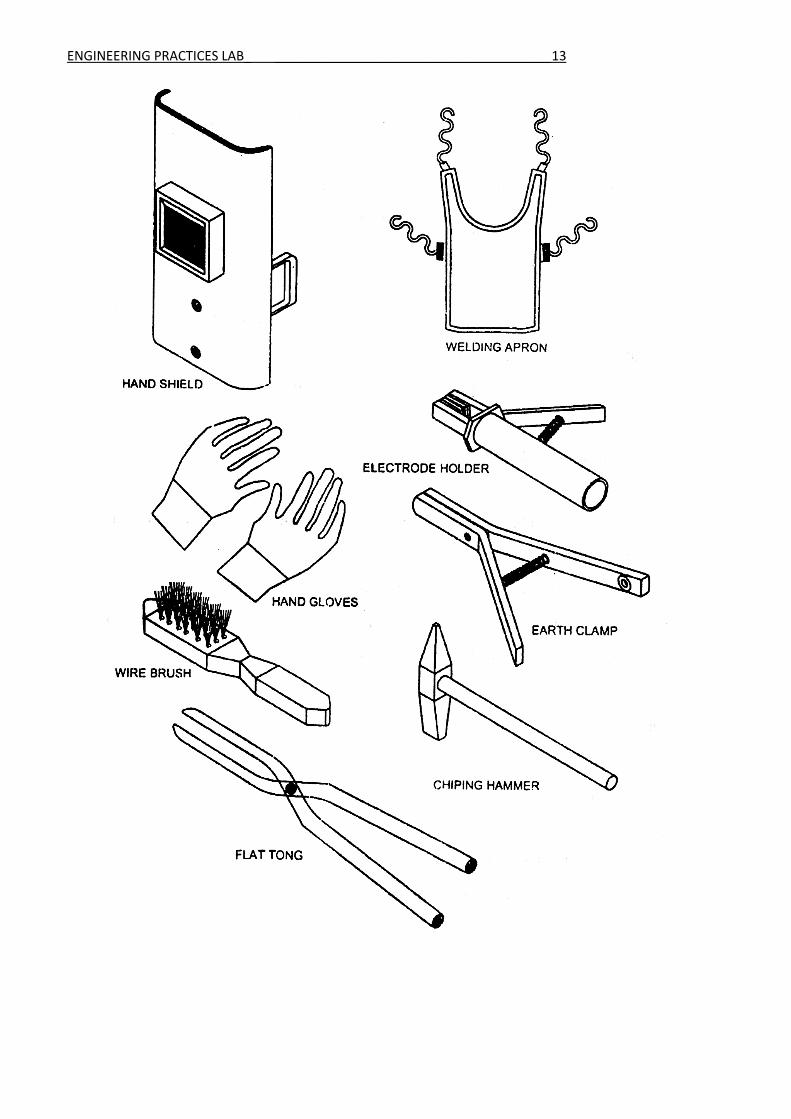
Three distinct flame settings are used, neutral, oxidising and carburizing. Welding is generally carried
out using the neutral flame setting which has equal quantities of oxygen and acetylene. The oxidising
flame is obtained by increasing just the oxygen flow rate while the carburising flame is achieved by
increasing acetylene flow in relation to oxygen flow. Because steel melts at a temperature above
ENGINEERING PRACTICES LAB_ ______________________________________10
1,500˚C, the mixture of oxygen and acetylene is used as it is the only gas combination with enough
heat to weld steel. However, other gases such as propane, hydrogen and coal gas can be used for
joining lower melting point non-ferrous metals, and for brazing and silver soldering.
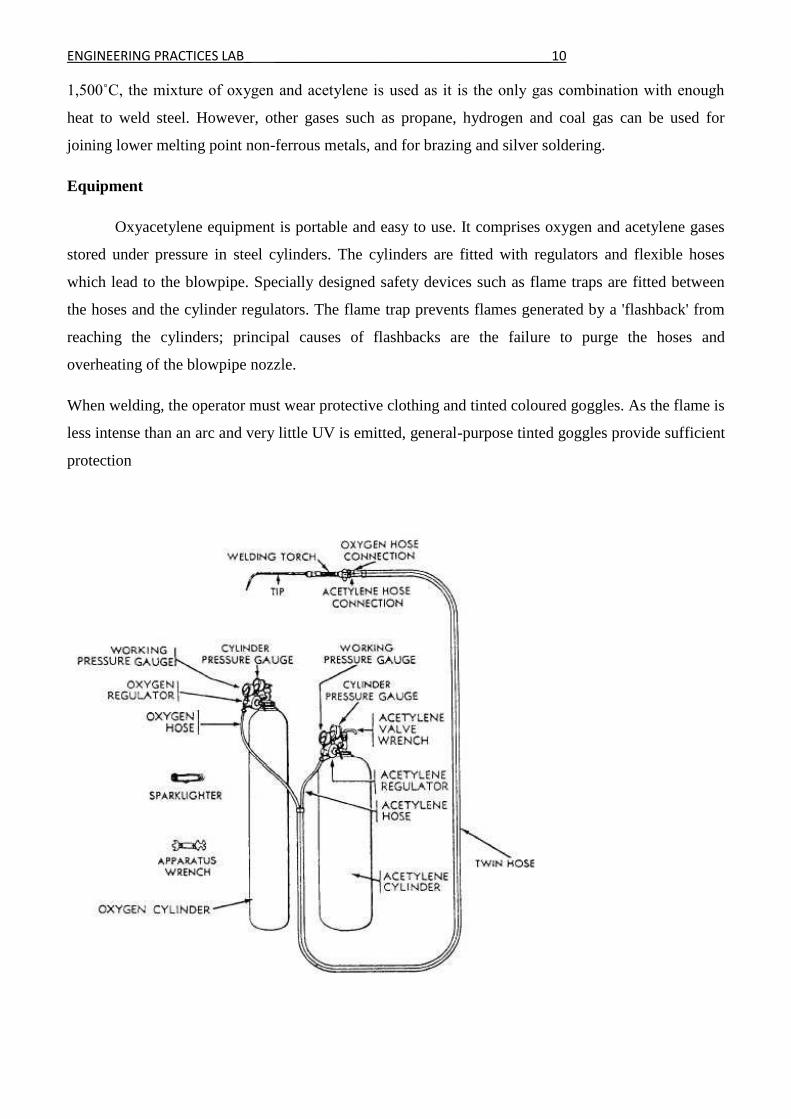
Equipment
Oxyacetylene equipment is portable and easy to use. It comprises oxygen and acetylene gases
stored under pressure in steel cylinders. The cylinders are fitted with regulators and flexible hoses
which lead to the blowpipe. Specially designed safety devices such as flame traps are fitted between
the hoses and the cylinder regulators. The flame trap prevents flames generated by a 'flashback' from
reaching the cylinders; principal causes of flashbacks are the failure to purge the hoses and
overheating of the blowpipe nozzle.
When welding, the operator must wear protective clothing and tinted coloured goggles. As the flame is
less intense than an arc and very little UV is emitted, general-purpose tinted goggles provide sufficient
protection
ENGINEERING PRACTICES LAB_ ______________________________________11
Neutral Flame
As the supply of oxygen to the blowpipe is further increased; the flame contracts and the
white cone become clearly defined, assuming a definite rounded shape. At this stage approximately
equal quantities of acetylene and oxygen are being used and the combustion is complete, all the carbon
supplied by the acetylene is being consumed and the maximum heat given out. The flame is now
neutral, and this type of flame is the one most extensively used by the welder, who should make
himself thoroughly familiar with its appearance and characteristics.
Carburising Flame
This is a flame in which an excess of acetylene is burning, i.e. combustion is incomplete and
unconsumed carbon is present. When lighting the blowpipe the acetylene is turned on first and ignited,
giving a very smoky yellow flame of abnormal size, showing two cones of flame in addition to an
outer envelope; this is an exaggerated form of the carburising flame, but gives out comparatively little
heat and is of little use for welding.
Oxidising Flame
A further increase in the oxygen supply will produce an oxidising flame in which there is
more oxygen than is required for complete combustion. The inner cone will become shorter and
sharper, the flame will turn a deeper purple colour and emit a characteristic slight "hiss", while the
molten metal will be less fluid and tranquil during welding and excessive sparking will occur. An
oxidising flame is only used for special applications, and should never be used for welding
Welding Tools and Safety Equipments
Goggles
Goggles are forms of protective eyewear that usually enclose or protect the eye area in order to
prevent particulates, infectious fluids, or chemicals from striking.
Face Shield
Face shield is used to protect the eyes of the welder from the little sparks produced during
welding. It is normally held in hand.
Hand Gloves
Hand gloves are used to protect the hands from electrical shock, arc radiation and hot spatters.
ENGINEERING PRACTICES LAB_ ______________________________________12
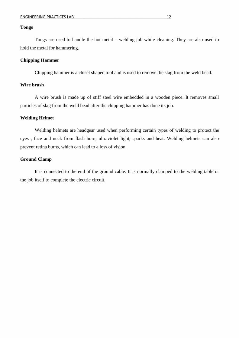
Tongs
Tongs are used to handle the hot metal – welding job while cleaning. They are also used to
hold the metal for hammering.
Chipping Hammer
Chipping hammer is a chisel shaped tool and is used to remove the slag from the weld bead.
Wire brush
A wire brush is made up of stiff steel wire embedded in a wooden piece. It removes small
particles of slag from the weld bead after the chipping hammer has done its job.
Welding Helmet
Welding helmets are headgear used when performing certain types of welding to protect the
eyes , face and neck from flash burn, ultraviolet light, sparks and heat. Welding helmets can also
prevent retina burns, which can lead to a loss of vision.
Ground Clamp
It is connected to the end of the ground cable. It is normally clamped to the welding table or
the job itself to complete the electric circuit.
ENGINEERING PRACTICES LAB_ ______________________________________13

ENGINEERING PRACTICES LAB_ ______________________________________14
Advantages of Arc Welding
1. A big range of metals and their alloys can be welded
2. Welding equipment is portable and the cost is fairly low
3. Flux shielded manual metal arc welding is the simplest of all the arc welding processes.
4. The applications of the arc welding are innumerable, because of the availability of wide variety
of electrodes.
5. Welding can be carried out in any position with highest weld quality.
Disadvantages of arc welding
1. Because of the limited length of each electrode and brittle flux coating on it, mechanization is
difficult.
2. In welding long joints, as one electrode finishes, the weld is to be progressed with the next
electrode. A defect may occur at the place where welding is restarted with the new electrode.
Applications
1. In reservoir tank, boiler and pressure vessel fabrications
2. Ship building
3. Pipes and pen stock joining
4. Building and bridge construction
5. Automotive and air craft industry
ENGINEERING PRACTICES LAB_ ______________________________________15
ENGINEERING PRACTICES LAB_ ______________________________________16
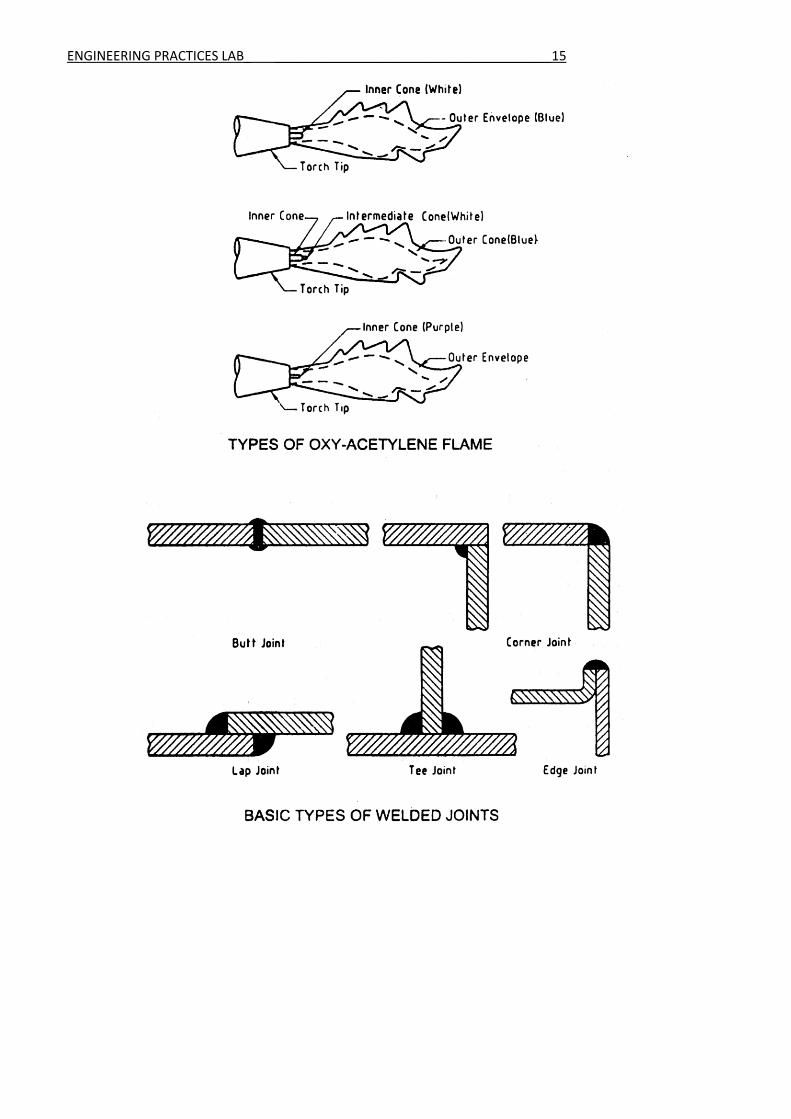
Types of Joints
The joints used in welding are
1. Butt joint 2. Lap joint 3. Edge joint
4. T – joint 5. Corner joint
1. Butt joint
It is used to join the ends or edges of plates lying in the same plane. Plates having thickness less
than 5mm do not require edge preparation but plates having thickness more than 5mm require edge
preparation on both sides.
2. Lap joint
It is used to join two over lapping pieces so that the edges of each piece are welded to the surface
of the other. It is used on plates less than 3mm thickness. Common types are single lap and double lap
joint. Edge preparation is not required for these joints.
3. Edge joint
It is used to weld two parallel plates. This is economical for joining thin plates up to 6mm. This
joint is often used in sheet metal work. It is suitable for severe loading.
4. T – joint
It is used to weld two perpendicular plates. This is economical for joining thin plates up to 3mm.
This joint is often used in structures.
5. Corner joint
It is used to join the edges of two pieces whose surfaces are approximately at right angles to each
other. It is common in the construction of boxes, tanks, frames and other similar items. Edge
preparation is not necessary for these joints.

ENGINEERING PRACTICES LAB_ ______________________________________17
ENGINEERING PRACTICES LAB_ ______________________________________18
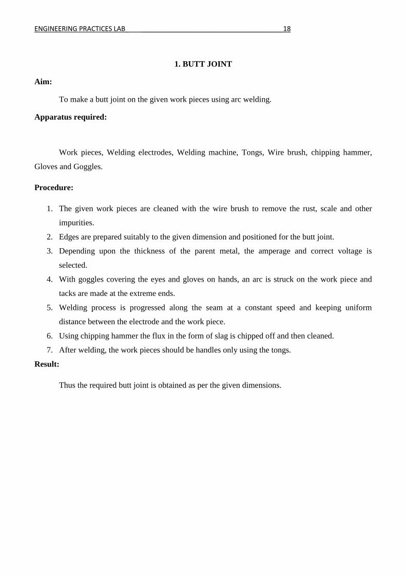
1. BUTT JOINT
Aim:
To make a butt joint on the given work pieces using arc welding.
Apparatus required:
Work pieces, Welding electrodes, Welding machine, Tongs, Wire brush, chipping hammer,
Gloves and Goggles.
Procedure:
1. The given work pieces are cleaned with the wire brush to remove the rust, scale and other
impurities.
2. Edges are prepared suitably to the given dimension and positioned for the butt joint.
3. Depending upon the thickness of the parent metal, the amperage and correct voltage is
selected.
4. With goggles covering the eyes and gloves on hands, an arc is struck on the work piece and
tacks are made at the extreme ends.
5. Welding process is progressed along the seam at a constant speed and keeping uniform
distance between the electrode and the work piece.
6. Using chipping hammer the flux in the form of slag is chipped off and then cleaned.
7. After welding, the work pieces should be handles only using the tongs.
Result:
Thus the required butt joint is obtained as per the given dimensions.

ENGINEERING PRACTICES LAB_ ______________________________________19
VIVA QUESTIONS AND ANSWERS
1. Name the types of welding.
(i) Arc welding (ii) Argon welding (Iii) Gas welding (iv) Tig welding (v) Mig welding (vi)
Spot welding
2. Which is are the types of joint?
Butt joint, T - joint, Lap joint.
3. What is welding?
Joining of two similar metals
4. Name the welding tools used in workshop.
Welding holder, welding rod, hand shield, hand gloves, chipping hammer, wire brush
5. Which outer cover is on the welding rod?
Silicon
6. What is the use of welding holder?
It hold the electrode firmly.
7. What is the use of hand shield?
It protects the face from sparks.
8. What is the use of hand gloves?
It protects the hands from sparks.
9. What is the use of chipping hammer?
It is used to remove the waste material from welded metal.
10. What is the use of wire brush?
It is used to clean the outer surface of welded metal.
ENGINEERING PRACTICES LAB_ ______________________________________20
ENGINEERING PRACTICES LAB_ ______________________________________21
2. LAP JOINT
Aim:
To make a lap joint on the given work pieces using arc welding.
Apparatus required:
Work pieces, Welding electrodes, Welding machine, Tongs, Wire brush, chipping hammer,
Gloves and Goggles.
Procedure:
1. The given work pieces are cleaned with the wire brush to remove the rust, scale and other
impurities.
2. Edges are prepared suitably to the given dimension and positioned one over another for the lap
joint.
3. Depending upon the thickness of the parent metal, the amperage and correct voltage is
selected.
4. With goggles covering the eyes and gloves on hands, an arc is struck on the work piece and
tacks are made at the extreme ends.
5. Welding process is progressed along the seam at a constant speed and keeping uniform
distance between the electrode and the work piece.
6. Using chipping hammer the flux in the form of slag is chipped off and then cleaned.
7. After welding, the work pieces should be handles only using the tongs.
Result:
Thus the required lap joint is obtained as per the given dimensions.
ENGINEERING PRACTICES LAB_ ______________________________________22
VIVA QUESTIONS AND ANSWERS
1. Which welding process uses non-consumable electrodes?
TIG welding
2. What is gas welding?
Mixture of gases is used to produce high temperature flame.
3. What is filler material?
It is the material added to the weld pool to assist in filling the gap.
4. What is flux?
Flux avoids oxidation in welding flame by giving a cover.
5. What are the advantages of using LPG over acetylene for cutting?
LPG fuel produces rich flame for cutting process.
6. Which equipment is used to supply power for welding?
Welding transformer
7. What is over head welding?
Welding done at the top of welding booth is called overhead welding.
8. What are the applications of welding?
Fabrication of steel windows and rods.
9. What is flux change in welding?
Flux change is done to switch from one type of welding to other.
10. What are the advantages of using electric arc welding?
EAW can be done without the use of oxygen cylinder.

ENGINEERING PRACTICES LAB_ ______________________________________23
ENGINEERING PRACTICES LAB_ ______________________________________24
3. T - JOINT
Aim:
To make a T - joint on the given work pieces using arc welding.
Apparatus required:
Work pieces, Welding electrodes, Welding machine, Tongs, Wire brush, chipping hammer,
Gloves and Goggles.
Procedure:
1. The given work pieces are cleaned with the wire brush to remove the rust, scale and other
impurities.
2. Edges are prepared suitably to the given dimension and positioned at right angles for the tee
joint.
3. Depending upon the thickness of the parent metal, the amperage and correct voltage is
selected.
4. With goggles covering the eyes and gloves on hands, an arc is struck on the work piece and
tacks are made at the extreme ends.
5. Welding process is progressed along the seam at a constant speed and keeping uniform
distance between the electrode and the work piece.
6. Using chipping hammer the flux in the form of slag is chipped off and then cleaned.
7. After welding, the work pieces should be handles only using the tongs.
Result:
Thus the required T - joint is obtained as per the given dimensions.

ENGINEERING PRACTICES LAB_ ______________________________________25
VIVA QUESTIONS AND ANSWERS
1. What is arc welding?
Electric arc is produced between carbon electrode and work piece to produce heat.
2. What is electrode?
Filler rods used in arc welding are called electrodes.
3. Name the materials used for coating on electrodes.
Copper, Carbon and Graphite.
4. What are the types of resistance welding?
Spot welding, Projection welding and Butt welding.
5. What are the welding defects?
Undercut, Cracking and Incomplete penetration.
6. What is coating done on electrode surface?
Coating is done to avoid melting of electrode.
7. What is butt joint?
Work pieces are welded to either sides.
8. What is lap joint?
Work pieces are welded one over other.
9. What is T- joint?
Work pieces are welded at perpendicular to each other.
10. What is corner joint?
Work pieces are welded at the corners.

ENGINEERING PRACTICES LAB_ ______________________________________26
ENGINEERING PRACTICES LAB_ ______________________________________27
LATHE
The lathe is used for producing cylindrical work. The work piece is rotated while the cutting
tool movement is controlled by the machine. The lathe is primarily used for cylindrical work. The
lathe may also be used for: Boring, drilling, tapping, turning, facing, threading, polishing, grooving,
knurling etc.
The purpose of a lathe is to rotate a part against a tool whose position it controls. It is useful for
fabricating parts and/or features that have a circular cross section. The spindle is the part of the lathe
that rotates. Various work holding attachments such as three jaw chucks, collets, and centers can be
held in the spindle. The spindle is driven by an electric motor through a system of belt drives and/or
gear trains. Spindle speed is controlled by varying the geometry of the drive train.
The tailstock can be used to support the end of the work piece with a center, or to hold tools for
drilling, reaming, threading, or cutting tapers. It can be adjusted in position along the ways to
accommodate different length work pieces. The ram can be fed along the axis of rotation with the
tailstock hand wheel.
The carriage controls and supports the cutting tool. It consists of: A saddle that mates with and
slides along the ways, an apron that controls the feed mechanisms, a cross slide that controls
transverse motion of the tool (toward or away from the operator), a tool compound that adjusts to
permit angular tool movement and a tool post T-slot that holds the tool post.
Feed, Speed, And Depth of Cut
Cutting speed is defined as the speed at which the work moves with respect to the tool. Feed
rate is defined as the distance the tool travels during one revolution of the part. Cutting speed and feed
determines the surface finish, power requirements, and material removal rate. The primary factor in
choosing feed and speed is the material to be cut. However, one should also consider material of the
tool, rigidity of the work piece, size and condition of the lathe, and depth of cut. To calculate the
proper spindle speed, divide the desired cutting speed by the circumference of the work.

ENGINEERING PRACTICES LAB_ ______________________________________28
Parts of Lathe
Head Stock
The headstock houses the main spindle , speed change mechanism , and change gears The
headstock is required to be made as robust as possible due to the cutting forces involved, which can
distort a lightly built housing, and induce harmonic vibrations that will transfer through to the work
piece, reducing the quality of the finished work piece
Bed
The bed is a robust base that connects to the headstock and permits the carriage and tailstock to
be aligned parallel with the axis of the spindle. This is facilitated by hardened and ground ways which
restrain the carriage and tailstock in a set track. The carriage travels by means of a rack and pinion
system, leads crew of accurate pitch, or feed screw.

ENGINEERING PRACTICES LAB_ ______________________________________29
Feed and lead screws
The feed screw is a long driveshaft that allows a series of gears to drive the carriage
mechanisms. These gears are located in the apron of the carriage. Both the feed screw and lead screw
are driven by either the change gears or an intermediate gearbox known as a quick change gearbox or
Norton gearbox. These intermediate gears allow the correct ratio and direction to be set for cutting
threads or worm gears. Tumbler gears are provided between the spindle and gear train that enables the
gear train of the correct ratio and direction to be introduced. This provides a constant relationship
between the number of turns the spindle makes, to the number of turns the lead screw makes. This
ratio allows screw threads to be cut on the work piece without the aid of a die.
Carriage
In its simplest form the carriage holds the tool bit and moves it longitudinally (turning) or
perpendicularly (facing) under the control of the operator. The operator moves the carriage manually
via the hand wheel or automatically by engaging the feed screw with the carriage feed mechanism, this
provides some relief for the operator as the movement of the carriage becomes power assisted. The
hand wheels on the carriage and its related slides are usually calibrated both for ease of use and to
assist in making reproducible cuts.
Cross-slide
The cross-slide stands atop the carriage and has a lead screw that travels perpendicular to the
main spindle axis, this permit facing operations to be performed. This lead screw can be engaged with
the feed screw (mentioned previously) to provide automated movement to the cross-slide; only one
direction can be engaged at a time as an interlock mechanism will shut out the second gear train.
Compound rest
The compound rest is the part of the machine where the tool post is mounted. It provides a
smaller amount of movement along its axis via another lead screw. The compound rest axis can be
adjusted independently of the carriage or cross-slide. It is utilized when turning tapers, when screw
cutting or to obtain finer feeds than the lead screw normally permits.
ENGINEERING PRACTICES LAB_ ______________________________________30
Tool post
The tool bit is mounted in the tool post which may be of the American lantern style, traditional
4 sided square styles, or in a quick change style. The advantage of a quick change set-up is to allow an
unlimited number of tools to be used (up to the number of holders available) rather than being limited
to 1 tool with the lantern style, or 3 to 4 tools with the 4 sided type.
Tail Stock
The tailstock is a tool holder directly mounted on the spindle axis, opposite the headstock. The
spindle does not rotate but does travel longitudinally under the action of a lead screw and hand wheel.
The spindle includes a taper to hold drill bits, centers and other tooling. The tailstock can be
positioned along the bed and clamped in position as required. There is also provision to offset the
tailstock from the spindles axis; this is useful for turning small tapers.
Lathe Operations
Turning
Turning is the machining operation that produces cylindrical parts. In its basic form, it can be
defined as the machining of an external surface:
• with the work piece rotating,
• with a single-point cutting tool, and
• with the cutting tool feeding parallel to the axis of the work piece and at a distance that will
remove the outer surface of the work.
Taper turning is practically the same, except that the cutter path is at an angle to the work axis.
Similarly, in contour turning, the distance of the cutter from the work axis is varied to produce the
desired shape
Facing
Facing is the producing of a flat surface as the result of a tool's being fed across the end of the
rotating work piece. Unless the work is held on a mandrel, if both ends of the work are to be faced, it
must be turned end for end after the first end is completed and the facing operation repeated. The
cutting speed should be determined from the largest diameter of the surface to be faced. Facing may be
ENGINEERING PRACTICES LAB_ ______________________________________31
done either from the outside inward or from the center outward. In either case, the point of the tool
must be set exactly at the height of the center of rotation.
Parting
Parting is the operation by which one section of a work piece is severed from the remainder by
means of a cutoff tool. Because cutting tools are quite thin and must have considerable overhang, this
process is less accurate and more difficult. The tool should be set exactly at the height of the axis of
rotation, be kept sharp, have proper clearance angles, and be fed into the work piece at a proper and
uniform feed rate.
Drilling
A lathe can also be used to drill holes accurately concentric with the centerline of a cylindrical
part. First, install a drill chuck into the tail stock. Make certain that the tang on the back of the drill
chuck seats properly in the tail stock. Withdraw the jaws of the chuck and tap the chuck in place with
a soft hammer.

ENGINEERING PRACTICES LAB_ ______________________________________32
Move the saddle forward to make room for the tailstock. Move the tailstock into position, and lock the
bit in place. Before starting the machine, turn the spindle by hand. Just move the saddle forward, so it
could interfere with the rotation of the lathe chuck. Always use a center drill to start the hole. .
ENGINEERING PRACTICES LAB_ ______________________________________33
Boring
Boring is an operation in which a hole is enlarged with a single point cutting tool. A boring bar
is used to support the cutting tool as it extends into the hole. Because of the extension of the boring
bar, the tool is supported less rigidly and is more likely to chatter. This can be corrected by using
slower spindle speeds or by grinding a smaller radius on the nose of the tool.
Single Point Thread Turning
External threads can be cut with a die and internal threads can be cut with a tap. But for some
diameters, no die or tap is available. In these cases, threads can be cut on a lathe. A special cutting tool
should be used, typically with a 60 degree nose angle. To form threads with a specified number of
threads per inch, the spindle is mechanically coupled to the carriage lead screw. Procedures vary for
different machines
ENGINEERING PRACTICES LAB_ ______________________________________34
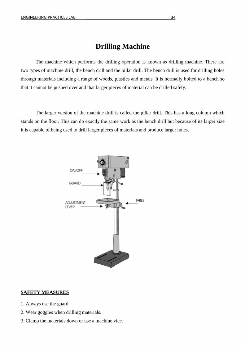
Drilling Machine
The machine which performs the drilling operation is known as drilling machine. There are
two types of machine drill, the bench drill and the pillar drill. The bench drill is used for drilling holes
through materials including a range of woods, plastics and metals. It is normally bolted to a bench so
that it cannot be pushed over and that larger pieces of material can be drilled safely.
The larger version of the machine drill is called the pillar drill. This has a long column which
stands on the floor. This can do exactly the same work as the bench drill but because of its larger size
it is capable of being used to drill larger pieces of materials and produce larger holes.
SAFETY MEASURES
1. Always use the guard.
2. Wear goggles when drilling materials.
3. Clamp the materials down or use a machine vice.

ENGINEERING PRACTICES LAB_ ______________________________________35
4. Never hold materials by hand while drilling.
5. Always allow the ‘chippings’ to clear the drill by drilling a small amount at a time.
6. Follow all teacher instructions carefully.
TYPES OF DRILLING MACHINE
1. Portable drilling machine
2. Sensitive drilling machine
3. Upright drilling machine
4. Radial drilling machine
5. Gang drilling machine
6. Multi spindle drilling machine
Bench Drill
The bench drill is a smaller version of the pillar drill. This type of machine drill is used for
drilling light weight pieces of material. The work piece is held safely in a hand vice which is held in
the hand. NEVER hold work directly in the hand when drilling. The on and off buttons are found on
the left hand side of the machine and the handle controlling the movement of the drill on the right.
Most bench drills will also have a foot switch for turning off the drill. The hand vice is one safe way of
holding material whilst drilling. It has two jaws that are closed by turning a wing nut.
Drilling Operations
1. Drilling
It is the operation by which circular holes can be produced by rotating a tool called drill bit against
the work piece. Using centre punch the centre of the hole is marked before drilling. The hole produced
by drilling will be rough and of less accuracy.
2. Reaming
It is the operation of finishing and sizing the already drilled hole. The tool used is called reamer. It
removes very little amount of metal to finish the hole.

ENGINEERING PRACTICES LAB_ ______________________________________36
3. Boring
The operation to enlarge the drilled hole is called boring. For boring, the cutter is held in a boring
bar and is fixed to the spindle. It gives good surface finish.
4. Counter boring
To seat the heads of socket, screw and studs, a drilled hole is enlarged to a given depth. This
operation is called counter boring.
5. Counter sinking
The operation of machining a conical enlargement at the top of a drilled hole is called counter
sinking.
ENGINEERING PRACTICES LAB_ ______________________________________37
ENGINEERING PRACTICES LAB_ ______________________________________38
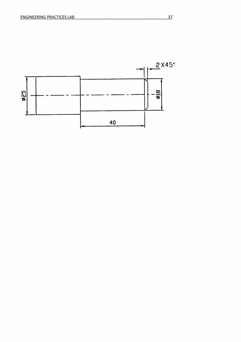
1. TURNING, FACING AND CHAMFERING
Aim To perform turning, facing and chamfering on a cylindrical work piece
Tools Required
1. Lathe
2. Three jaw chuck
3. Chuck key
4. Single point cutting tool
5. Vernier caliper
Procedure
1. Loosen the jaws in the chuck using chuck key to position the work piece and then tighten
the jaws.
2. Fix the single point cutting tool in the tool post
3. Switch on the lathe, move the carriage near the work piece and give a small cross feed.
Move the carriage slowly to the required length
4. Bring the carriage to the original position, give a small cross feed and repeat the steps until
the required diameter is obtained. At the end give very small feed to get smooth surface.
5. For facing operation, the cutting tool is tilted by 30˚ and move the carriage to make the tool
touch the end surface of the work piece.
6. Give small feed in longitudinal direction and then move the tool inwards using cross slide.
7. For chamfering operation, set the cross slide to 45˚, give small feed in longitudinal
direction and then move the tool using cross slide.
8. Check the dimensions regularly using vernier caliper.
Result
Thus the turning, facing and chamfering operations are carried out on the given work piece
ENGINEERING PRACTICES LAB_ ______________________________________39
VIVA QUESTIONS AND ANSWERS
1. What is a lathe?
Lathe is a machine, which removes the metal from a piece of work to the required shape and size.
2. What is the various operations can be performed on a lathe?
Turning, Facing, Chamfering, Drilling, Thread cutting, Grooving, Knurling and Tapping
3. What are principle parts of lathe?
Red, headstock, tailstock, carriage, cross slide, tool post
4. What are the types of headstock?
Back geared type, all geared type
5. State the various parts mounted on the carriage.
Saddle, compound rest, cross slide, tool Post
6. What are the four types of tool post?
1. Single screw
2. Open side
3. Four bolt
4. Four way
7. What is a Chamfering?
A cut that is made on the edge of work piece at 45degrees angle to the adjacent principal faces.
8. State any two specification of lathe.
1. The height of centers from the bed
2. The maximum length of the bed
9. List any three types of lathe.
1. Engine lathe
2. Bench lathe
3. Tool room lathe
10. What is a semi-automatic lathe?
The lathe in which all the machining operations are performed automatically and loading and
unloading of work piece, coolant on or off is performed manually
ENGINEERING PRACTICES LAB_ ______________________________________40

ENGINEERING PRACTICES LAB_ ______________________________________41
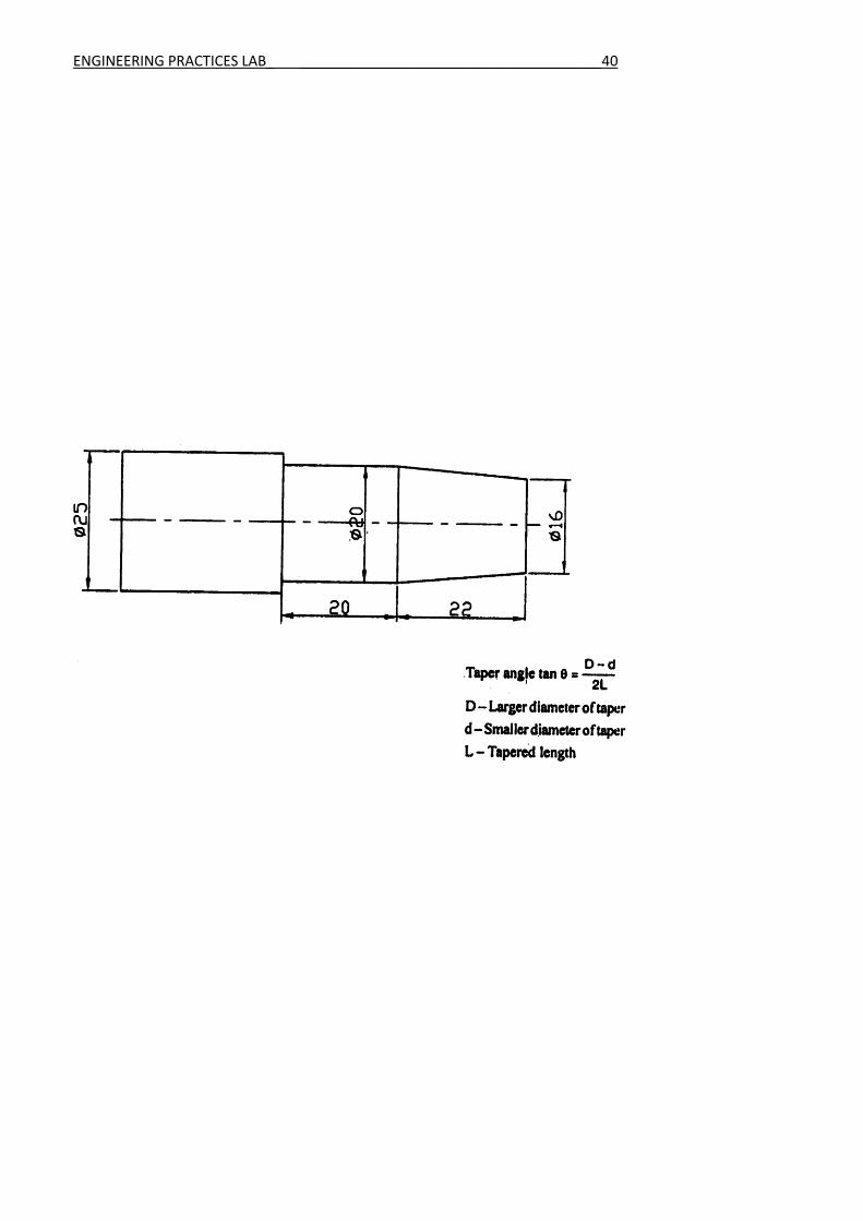
2. TAPER TURNING
Aim
To perform taper turning operation on a cylindrical work piece
Tools Required
1. Lathe
2. Three jaw chuck
3. Chuck key
4. Single point cutting tool
5. Vernier caliper
Procedure
1. Loosen the jaws in the chuck using chuck key to position the work piece and then tighten
the jaws.
2. Fix the single point cutting tool in the tool post
3. Switch on the lathe, move the carriage near the work piece and give a small cross feed.
Move the carriage slowly to the required length
4. Bring the carriage to the original position, give a small cross feed and repeat the steps until
the required diameter is obtained. At the end give very small feed to get smooth surface.
5. To produce a taper, rotate and set the cross slide to the required angle.
6. Give a small feed and then move the tool using the cross slide. Repeat the steps to complete
the taper.
7. Check the dimensions regularly using vernier caliper.
Result
Thus the taper turning operation is carried out on the given work piece
ENGINEERING PRACTICES LAB_ ______________________________________42
VIVA QUESTIONS AND ANSWERS
1. What is copying lathe?
The tool of the lathe follows a template or master through a stylus or tracer
2. State the various feed mechanisms used for obtaining automatic feed.
a. Tumbler gear mechanism
b. Quick change gearbox
c. Tumbler gear- Quick change gearbox
3. List any four holding devices.
d. Chucks
e. Centers
f. Face plate
g. Angle plate
4. What are the different operations performed on the lathe?
Centering, straight turning, rough turning, finish turning, shoulder turning, facing, chamfering, knurling, etc
5. Define the term ‘Conicity’.
The ratio of the difference in diameters of taper to its length k = (D-d)/l
d-smallerdia D-bigger dia
l-length of the work piece.
6. What is the use of chuck?
Chuck is used to hold the work piece firmly.
7. What are the types of chuck based on numbering?
Three jaw and four jaw Chuck.
8. What is the use of tail stock?
Tail stock is used to support the rear end of work piece.
9. Where is the motor located in lathe?
It is adjacent to the head stock.
10. What is the use of knurling?
It is to provide grip to the work piece.
ENGINEERING PRACTICES LAB_ ______________________________________43
ENGINEERING PRACTICES LAB_ ______________________________________44
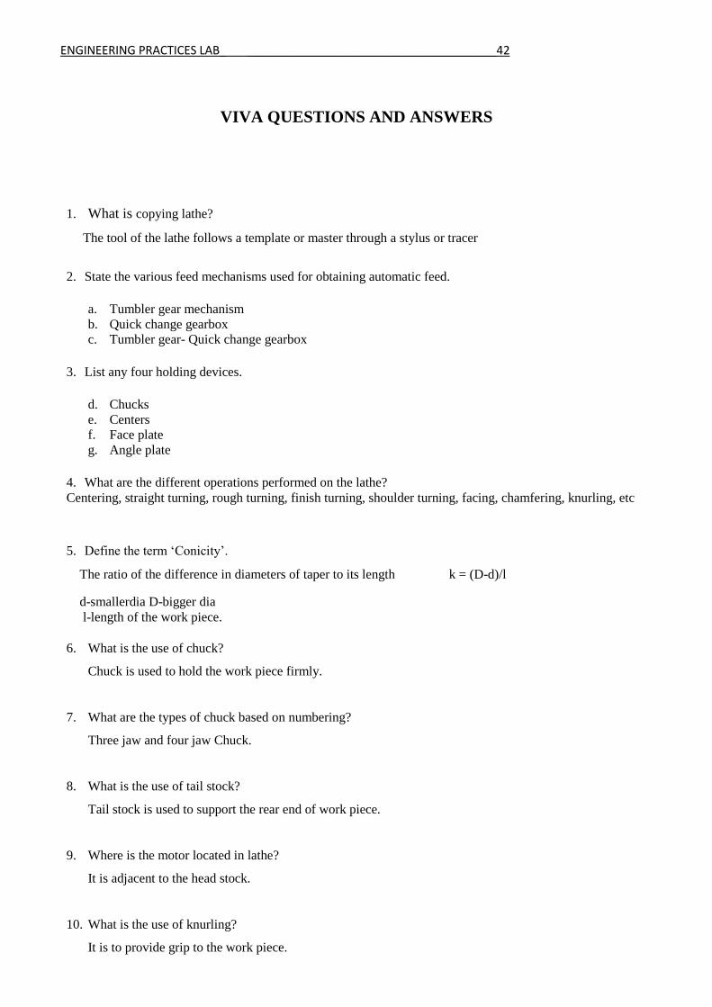
3. DRILLING AND TAPPING
Aim:
To make an internal thread on a given work piece as per the required dimensions using drilling
machine and tapping tool.
Tools Required:
1. Machine vice 2. Drilling machine
3. Drill bit 4. Tapping tool
5. Dot punch 6. Hammer etc.
Procedure:
1. The dimensions of the given work piece is checked as per the requirement.
2. The work piece is clamped in the vice and any two surfaces are filed to get right angle.
3. Drill bit of required size is fitted in the drill chuck of the drilling machine.
4. The mid point of the required hole is punched by using dot punch and hammer.
5. The punched dot is drilled by drilling machine.
6. After drilling the hole, they are tapped by using tap tool.
7. Finally the dimensions are checked.
Result:
Thus the given work piece is drilled and tapped to the required dimensions.

ENGINEERING PRACTICES LAB_ ______________________________________45
VIVA QUESTIONS AND ANSWERS
1. What is the use of drilling machine?
It used to makes holes of required size in work pieces.
2. What are the drilling operations?
Drilling, reaming, boring, counter boring and counter sinking.
3. What is Reaming?
It is the operation of finishing and sizing the already drilled hole. The tool used is called reamer. It
removes very little amount of metal to finish the hole.
4. What is Boring?
The operation to enlarge the drilled hole is called boring. For boring, the cutter is held in a boring bar
and is fixed to the spindle. It gives good surface finish.
5. What is counter boring?
To seat the heads of socket, screw and studs, a drilled hole is enlarged to a given depth. This operation
is called counter boring.
6. What is counter sinking?
The operation of machining a conical enlargement at the top of a drilled hole is called counter sinking.
7. What is the use of a guard?
It is used to protect the face from chips.
8. What is radial drilling machine?
The work piece is drilled at right angles to the drill bit.
9. Why is boring operation preferred?
Varying size of holes can be made from standard sizes.
10. Mention few applications of drilling.
Building construction, tool fabrication etc.

ENGINEERING PRACTICES LAB_ ______________________________________46
ENGINEERING PRACTICES LAB_ ______________________________________47
FOUNDRY
A foundry is a factory which produces metal castings from either ferrous or non-ferrous alloys.
Metals are turned into parts by melting the metal into a liquid, pouring the metal in a mold, and then
removing the mold material or casting. The most common metal alloys produced are aluminum and
cast iron. However, other metals, such as steel, magnesium, copper, tin, and zinc, can be processed.
A sand casting or a sand molded casting is a cast part produced by forming a mold from a sand
mixture and pouring molten liquid metal into the cavity in the mold. The mold is then cooled until the
metal has solidified. In the last stage the casting is separated from the mold. There are six steps in this
process:
1. Place a pattern in sand to create a mold.
2. Incorporate a gating system.
3. Remove the pattern.
4. Fill the mold cavity with molten metal.
5. Allow the metal to cool.
6. Break away the sand mold and remove the casting.
There are two main types of sand used for molding. "Green sand" is a mixture of silica sand,
clay, moisture and other additives. The "air set" method uses dry sand bonded to materials other than
clay, using a fast curing adhesive. When these are used, they are collectively called "air set" sand
castings to distinguish these from "green sand" castings. Two types of molding sand are natural
bonded (bank sand) and synthetic (lake sand), which is generally preferred due to its more consistent
composition.

ENGINEERING PRACTICES LAB_ ______________________________________48
Foundry hand tools
The hand tools commonly used in foundry are as follows.
1. Shovel
It is used for mixing molding sand and for filling molding sand into the flask. A shovel is
shown in fig. (a)
2. Riddle
Riddle is used for removing foreign materials from the moulding sand. It is shown in
fig. (b)
3. Rammer
This is used for packing or ramming the sand into the mould. Hand rammers are shown in fig.
(c) For large moulds, machine rammers are used.
4. Trowel
A trowel is used for smoothening the surfaces of the mould. It is shown in fig.(d)
5. Sprue pin

ENGINEERING PRACTICES LAB_ ______________________________________49
It is a conical wooden pin, which is used while making the mould, for making an opening to
pour the molten material into the cavity. A sprue pin is shown in fig. (e).
6. Vent rod
Vent rod is used for making small holes to permit gases to escape while the molten material is
being poured. Fig. (f) shows a vent rod.
7. Draw spike
This is used for drawing patterns from the sand. It has a loop at one end for pulling up the
pattern from the mould. Draw spike is shown in fig. (g)
8. Moulding boxes
These are also known as moulding flasks. Moulding boxes are rigid frames made of iron or
wood to hold the sand. The purpose of the flask is to impart necessary rigidity and strength to the
rammed sand. Complete process of moulding is done in the moulding boxes. They are usually made
in two parts, which are assembled with each other by pins on either side of the flasks. The top flask is
called cope and the bottom flask is called drag. If the boxes are made in three sections then the
middle one is called as cheek.

ENGINEERING PRACTICES LAB_ ______________________________________50
ENGINEERING PRACTICES LAB_ ______________________________________51
SMITHY
Black smithy or forging is an ancient trade. It consists of heating a metal stock till it acquires
sufficient plasticity, followed by hand forging, involving hammering, bending, pressing etc., till the
desired shape is attained.
Hand forging is the term used when the process is carried out by hand tools. The hand forging
process is generally employed for relatively small components. If power operated machines are used
for the purpose, it is known as machine forging.
Advantages of forging
1. Strength and toughness is high
2. Strength to weight ratio is high
3. Internal defects are eliminated.
A blacksmith is a person who creates objects from iron or steel by "forging" the metal; i.e., by
using tools to hammer, bend, cut, and otherwise shape it in its non-liquid form. Usually the metal is
heated until it glows red or orange as part of the forging process. Blacksmiths produce things like
wrought iron gates, grills, railings, light fixtures, furniture, sculpture, tools, agricultural implements,
decorative and religious items, cooking utensils etc.
Forging Operations
There are five basic operations or techniques employed in forging: drawing, shrinking,
bending, upsetting, and punching.
These operations generally employ hammer and anvil at a minimum, but smiths will also make
use of other tools and techniques to accommodate odd-sized or repetitive jobs.
Drawing
Drawing lengthens the metal by reducing one or both of the other two dimensions. As the
depth is reduced, the width narrowed, or both the piece is lengthened or "drawn out". As an example
of drawing, a smith making a wood chisel might flatten a square bar of steel, lengthening the metal,
reducing its depth but keeping its width consistent.
Upsetting

ENGINEERING PRACTICES LAB_ ______________________________________52
Upsetting is the process of making metal thicker in one dimension through shortening in the
other. One form is by heating the end of a rod and then hammering on it as one would drive a nail: the
rod gets shorter, and the hot part widens. An alternative to hammering on the hot end would be to
place the hot end on the anvil and hammer on the cold end, or to drop the rod, hot end down, onto a
piece of steel at floor level.
Shrinking
Shrinking, while similar to upsetting, is essentially the opposite process as drawing. As the
edge of a flat piece is curved,—as in the making of a bowl shape—the edge will become wavy as the
material bunches up in a shorter radius. At this point the wavy portion is heated and the waves are
gently pounded flat to conform to the desired shape.
Bending
Heating steel to an orange heat allows bending. Bending can be done with the hammer over the
horn or edge of the anvil, or by inserting the work into one of the holes in the top of the anvil and
swinging the free end to one side. Bends can be dressed and tightened or widened by hammering them
over the appropriately-shaped part of the anvil.
Punching
Punching may be done to create a decorative pattern, or to make a hole. For example, in
preparation for making a hammerhead, a smith would punch a hole in a heavy bar or rod for the
hammer handle. Punching is not limited to depressions and holes. It also includes cutting, or slitting
and drifting: these are done with a chisel.
Hand Forging Tools
All a smith needs is something to heat the metal, [something to hold the hot metal with,]
something to hit the metal on, and something to hit the metal with."
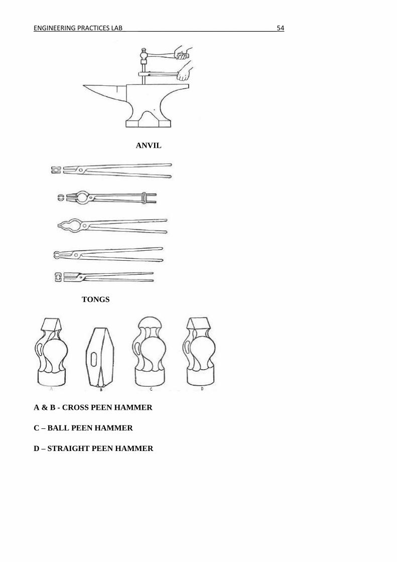
Anvil
The anvil at its simplest is a large block of iron or steel. Over time this has been refined to
provide a rounded horn to facilitate drawing and bending, a face for drawing and upsetting and
bending, and one or more holes to hold special tools (swages or hardies) and facilitate punching. Often
the flat surface of an anvil will be hardened steel, and the body made from tougher iron.
Tongs
ENGINEERING PRACTICES LAB_ ______________________________________53
Tongs are used to hold the hot metal. They come in a range of shapes and sizes. Intriguingly,
while tongs are needed for a great deal of blacksmithing, much work can be done by merely holding
the cold end with one's bare hand: steel is a fairly poor conductor of heat, and orange-hot steel at one
end would be cold to the touch a foot away or so.
Hammers
Blacksmiths' hammers tend to have one face and a peen. The peen is typically either a ball or a
blunt wedge (cross or straight peen depending on the orientation of the wedge to the handle) and is
used when drawing.
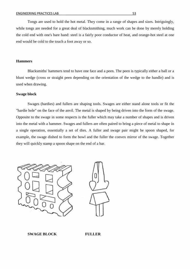
Swage block
Swages (hardies) and fullers are shaping tools. Swages are either stand alone tools or fit the
"hardie hole" on the face of the anvil. The metal is shaped by being driven into the form of the swage.
Opposite to the swage in some respects is the fuller which may take a number of shapes and is driven
into the metal with a hammer. Swages and fullers are often paired to bring a piece of metal to shape in
a single operation, essentially a set of dies. A fuller and swage pair might be spoon shaped, for
example, the swage dished to form the bowl and the fuller the convex mirror of the swage. Together
they will quickly stamp a spoon shape on the end of a bar.
SWAGE BLOCK FULLER
ENGINEERING PRACTICES LAB_ ______________________________________54
ANVIL
TONGS
A & B - CROSS PEEN HAMMER
C – BALL PEEN HAMMER
D – STRAIGHT PEEN HAMMER

ENGINEERING PRACTICES LAB_ ______________________________________55

ENGINEERING PRACTICES LAB_ ______________________________________56
SHEET METAL
Introduction
Sheet metal is simply metal formed into thin and flat pieces. It is one of the fundamental forms used in
metalworking, and can be cut and bent into a variety of different shapes. Countless everyday objects
are constructed of the material. Thicknesses can vary significantly, although extremely thin
thicknesses are considered foil or leaf, and pieces thicker than 6 mm (0.25 in) are considered plate.
Sheet metal is available as flat pieces or as a coiled strip. The coils are formed by running a continuous
sheet of metal through a roll slitter.
The thickness of the sheet metal is called its gauge. The gauge of sheet metal ranges from 30 gauge to
about 8 gauge. The higher the gauge, the thinner the metal is.
There are many different metals that can be made into sheet metal, such as aluminum, brass, copper,
steel, tin, nickel and titanium. For decorative uses, important sheet metals include silver, gold, and
platinum (platinum sheet metal is also utilized as a catalyst.)
Sheet metal has applications in car bodies, airplane wings, medical tables, roofs for building and many
other things. Sheet metal of iron and other materials with high magnetic permeability, also known as
laminated steel cores, has applications in transformers and electric machines. Historically, an
important use of sheet metal was in plate armor worn by cavalry, and sheet metal continues to have
many decorative uses, including in horse tack.
Sheet metal processing
The raw material for sheet metal manufacturing processes is the output of the rolling process.
Typically, sheets of metal are sold as flat, rectangular sheets of standard size. If the sheets are thin and
very long, they may be in the form of rolls. Therefore the first step in any sheet metal process is to cut
the correct shape and sized ‘blank’ from larger sheet.
ENGINEERING PRACTICES LAB_ ______________________________________57
Sheet metal processes
Sheet metal processes can be broken down into two major classifications and one minor classification
• Shearing processes - processes which apply shearing forces to cut, fracture, or separate the
material.
• Forming processes - processes which cause the metal to undergo desired shape changes
without failure, excessive thinning, or cracking. This includes bending and stretching.
• Finishing processes - processes which are used to improve the final surface characteristics.
Shearing Process
1. Punching: shearing process using a die and punch where the interior portion of the
sheared sheet is to be discarded.
2. Blanking: shearing process using a die and punch where the exterior portion of the
shearing operation is to be discarded.
3. Perforating: punching a number of holes in a sheet
4. Parting: shearing the sheet into two or more pieces
5. Notching: removing pieces from the edges
6. Lancing: leaving a tab without removing any material
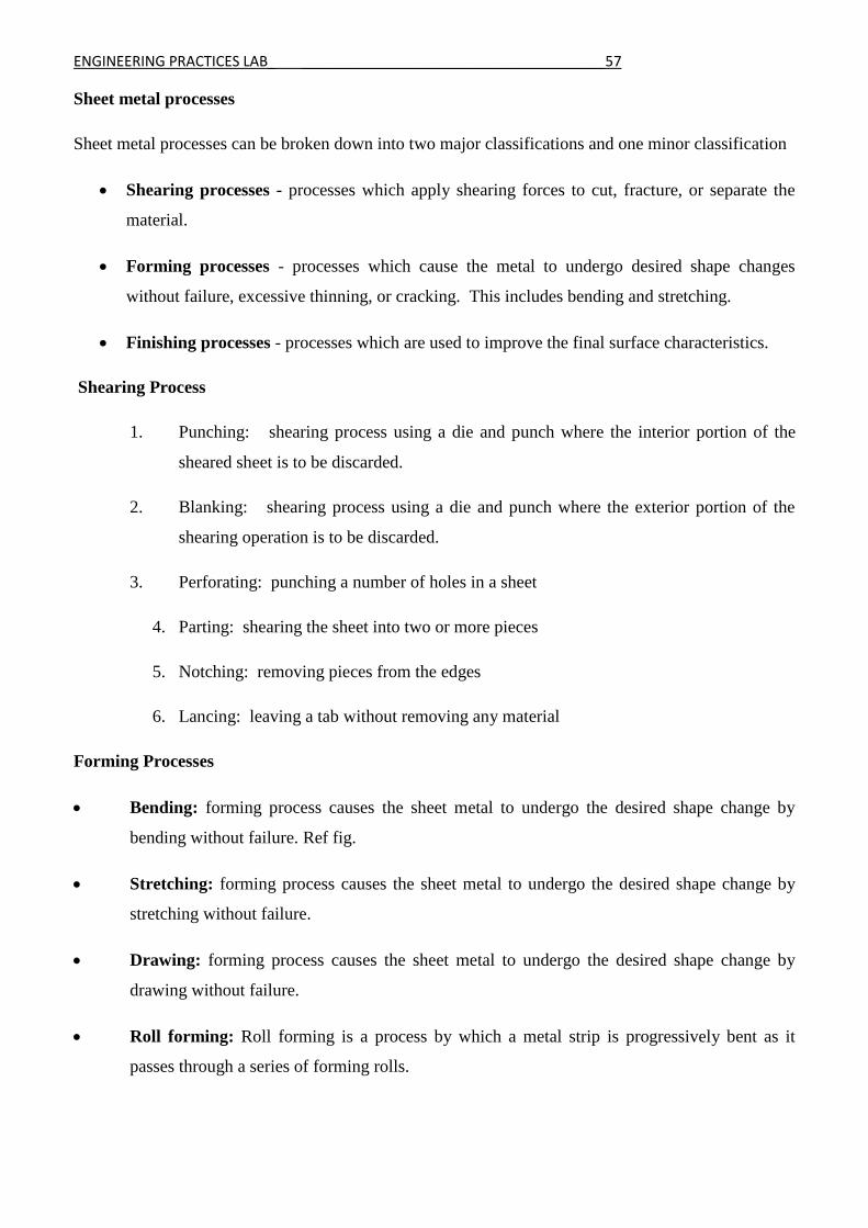
Forming Processes
• Bending: forming process causes the sheet metal to undergo the desired shape change by
bending without failure. Ref fig.
• Stretching: forming process causes the sheet metal to undergo the desired shape change by
stretching without failure.
• Drawing: forming process causes the sheet metal to undergo the desired shape change by
drawing without failure.
• Roll forming: Roll forming is a process by which a metal strip is progressively bent as it
passes through a series of forming rolls.
ENGINEERING PRACTICES LAB_ ______________________________________58
Common Die – Bending operations
Finishing processes
Material properties, geometry of the starting material, and the geometry of the desired final product
play important roles in determining the best process
Equipments
Basic sheet forming operations involve a press, punch, or ram and a set of dies
Presses
• Mechanical Press - The ram is actuated using a flywheel. Stroke motion is not uniform.
• Hydraulic Press - Longer strokes than mechanical presses, and develop full force throughout
the stroke. Stroke motion is of uniform speed, especially adapted to deep drawing operations.
Dies and Punches
• Simple- single operation with a single stroke
• Compound- two operations with a single stroke
• Combination- two operations at two stations
• Progressive- two or more operations at two or more stations with each press stroke, creates
what is called a strip development
ENGINEERING PRACTICES LAB_ ______________________________________59
Tools and Accessories
The various operations such as cutting, shearing, bending, folding etc. are performed by these tools.
Marking and measuring tools
• Steel Rule - It is used to set out dimensions.
• Try Square - Try square is used for making and testing angles of 90degree
• Scriber – It used to scribe or mark lines on metal work pieces.
• Divider - This is used for marking circles, arcs, laying out perpendicular lines, bisecting lines,
etc
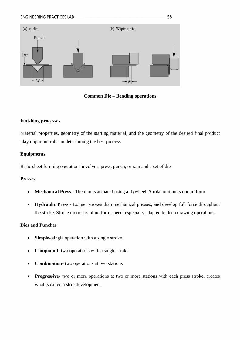
Cutting Tools
• Straight snip - They have straight jaws and used for straight line cutting. Ref fig.
• Curved snip - They have curved blades for making circular cuts. Ref fig.
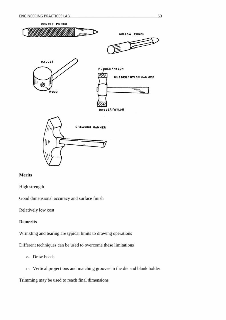
Striking Tools
Mallet - It is wooden-headed hammer of round or rectangular cross section. The striking face is made
flat to the work. A mallet is used to give light blows to the Sheet metal in bending and finishing. Ref
fig.
Hammers – Hammers are also used in sheet metal work for forming shapes. Commonly used
hammers are rubber / nylon hammers and creasing hammer.
ENGINEERING PRACTICES LAB_ ______________________________________60
Merits
High strength
Good dimensional accuracy and surface finish
Relatively low cost
Demerits
Wrinkling and tearing are typical limits to drawing operations
Different techniques can be used to overcome these limitations
o Draw beads
o Vertical projections and matching grooves in the die and blank holder
Trimming may be used to reach final dimensions

ENGINEERING PRACTICES LAB_ ______________________________________61
Applications
Roofings
Ductings
Vehicles body buildings like 3 wheelers, 4 wheelers, ships, aircrafts etc.
Furnitures, House hold articles and Railway equipment
ENGINEERING PRACTICES LAB_ ______________________________________62
ENGINEERING PRACTICES LAB_ ______________________________________63
1. CONE MAKING
Aim: To make a hollow cone out of the given sheet with specified dimensions.
Tools required:
1. Sheet metal 2. Anvil 3. Try square 4. Steel rule
5. Divider 6. Snip 7. Scriber
8. Mallet 9. File 10. Hand shearing machine
11. Protractor etc.
Materials required:
Tin or mild steel of suitable size.
Procedure:
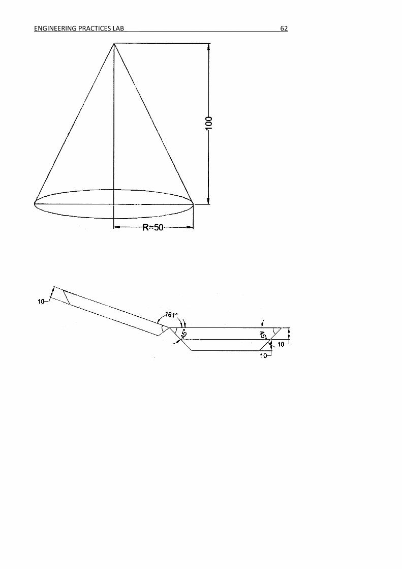
1. Development of cone for the given dimensions is drawn on the provided sheet metal using
protractor and scriber. (Sector of radius equal to the slant length of the cone and arc length
equal to the circumference of the cone)
2. Assume, joining allowance of 10 to 15mm on either side of the development.
3. The sheet metal is exactly cut as per the markings made on it using a straight shear / snip. The
burrs are removed using a file.
4. Then the edges are bent for a length of joining allowance. This is done with the help of a mallet
and an appropriate stake / anvil.
5. The sheet metal is then formed to the conical shape using a cylindrical stake / anvil and a
mallet as shown in fig.
6. Now the bent edges are made to overlap each other and are struck with a mallet to get the
required joint.
Result:
Thus the cone of given dimension is fabricated with the given sheet metal.
ENGINEERING PRACTICES LAB_ ______________________________________64
VIVA QUESTIONS AND ANSWERS
1. What is sheet metal work?
Sheet metal work is used for making, Cutting and bending of sheet metals to desired shape.
2. Which are the materials used for sheet metals?
(i) Galvanized iron (ii) Stainless steel (iii) Copper (iv) Aluminium
3. Name the sheet metal hand tools.
(i) Steel rule (ii) Vernier calliper (iii) Micrometer (iv) Scriber (v) Divider (vi) hammer (viii)
mallet(ix) Shears
4. What is G.I.?
G.I. is galvanized iron
5. What is shearing?
Shearing means sheet metal cutting
6. What is the name of vice used in fitting shop?
Bench vice
7. Name the different files?
(i)Flat file (ii) Square file (iii) Round file (iv) Triangular file (v) Half round file
8. What are the metals that can be used for sheet metal work?
Aluminium, Brass, Copper and steel.
9. What are the cutting tools?
Straight snip and Curved snip
10. What is Curved snip?
Curved blades are used for making circular cuts.
ENGINEERING PRACTICES LAB_ ______________________________________65
ENGINEERING PRACTICES LAB_ ______________________________________66
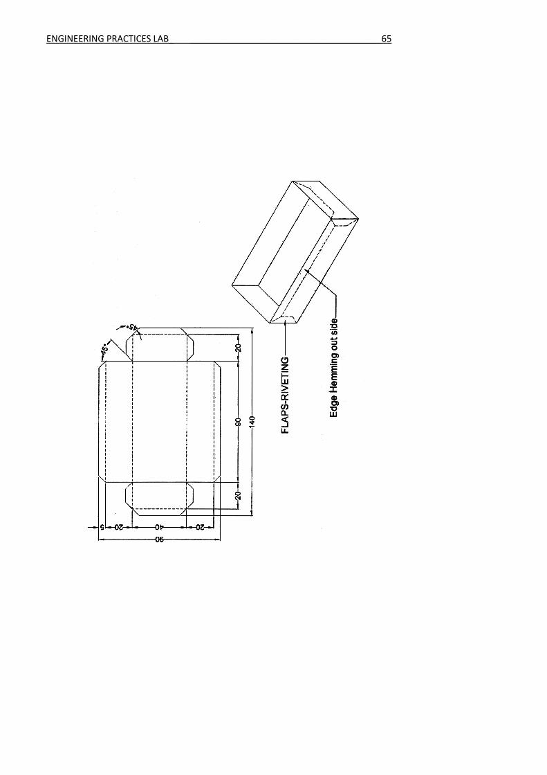
2. TRAY MAKING
Aim: To make a rectangular tray out of the given sheet with specified dimensions.
Tools required:
1. Sheet metal 2. Anvil 3. Try square 4. Steel rule
5. Divider 6. Snip 7. Scriber
8. Mallet 9. File 10. Hand shearing machine
11. Protractor etc.
Materials required:
Tin or mild steel of suitable size.
Procedure:
1. Development of the rectangular tray for the given dimensions is drawn on the provided sheet
metal using steel rule, protractor and scriber as shown in fig.
2. Assume some joining allowance on all sides of the development for locking the tray.
3. The sheet metal is exactly cut as per the markings made on it using a hand shearing machine or
snip. The burrs are removed using a file.
4. Single hemming is made on the four sides of the tray as shown in fig.
5. Four sides are bent to 90° using stake / anvil.
6. Then the edges are bent for the length of joining allowance and the edges are made to overlap
each other and are struck with a mallet to get the required joint.
Result:
Thus the rectangular tray of given dimension is fabricated with the given sheet metal.

ENGINEERING PRACTICES LAB_ ______________________________________67
VIVA QUESTIONS AND ANSWERS
1. What is a try square?
Try square is used for making and testing angles of 90degree
2. What is a Scriber?
It used to scribe or mark lines on metal work pieces.
3. What is a Divider?
This is used for marking circles, arcs, laying out perpendicular lines, bisecting lines, etc
4. What is a straight snip?
They have straight jaws and used for straight line cutting.
5. What is a Mallet?
It is wooden-headed hammer of round or rectangular cross section. The striking face is made
flat to the work.
6. What is a Hammer?
Hammer is also used in sheet metal work for forming shapes. Commonly used hammers are
rubber / nylon hammers and creasing hammer.
7. What is punching?
It is the shearing process using a die and punch where the interior portion of the sheared sheet
is to be discarded.
8. What is Blanking?
Shearing process using a die and punch where the exterior portion of the shearing operation is
to be discarded.
9. What is Perforating?
Punching a number of holes in a sheet
10. What is parting?
Shearing the sheet into two or more pieces

ENGINEERING PRACTICES LAB_ ______________________________________68
CENTRIFUGAL PUMP
A centrifugal pump is one of the simplest pieces of equipment in any process plant. Its
purpose is to convert energy of a prime mover (a electric motor or turbine) first into velocity or kinetic
energy and then into pressure energy of a fluid that is being pumped.
The energy changes occur by virtue of two main parts of the pump, the impeller and the volute
or diffuser. The impeller is the rotating part that converts driver energy into the kinetic energy. The
volute or diffuser is the stationary part that converts the kinetic energy into pressure energy.
Note: All of the forms of energy involved in a liquid flow system are expressed in terms of feet of
liquid i.e. head.
Generation of Centrifugal Force
The process liquid enters the suction nozzle and then into eye (center) of a revolving device
known as an impeller. When the impeller rotates, it spins the liquid sitting in the cavities between the
vanes outward and provides centrifugal acceleration. As liquid leaves the eye of the impeller, a low-
pressure area is created causing more liquid to flow toward the inlet. Because the impeller blades are
curved, the fluid is pushed in a tangential and radial direction by the centrifugal force. This force
acting inside the pump is the same one that keeps water inside a bucket that is rotating at the end of a
string. Figure below depicts a side cross-section of a centrifugal pump indicating the movement of the
liquid.

ENGINEERING PRACTICES LAB_ ______________________________________69
Conversion of Kinetic Energy to Pressure Energy
The key idea is that the energy created by the centrifugal force is kinetic energy. The amount
of energy given to the liquid is proportional to the velocity at the edge or vane tip of the impeller. The
faster the impeller revolves or the bigger the impeller is, then the higher will be the velocity of the
liquid at the vane tip and the greater the energy imparted to the liquid.
This kinetic energy of a liquid coming out of an impeller is harnessed by creating a resistance
to the flow. The first resistance is created by the pump volute (casing) that catches the liquid and
slows it down. In the discharge nozzle, the liquid further decelerates and its velocity is converted to
pressure according to Bernoulli’s principle.
Therefore, the head (pressure in terms of height of liquid) developed is approximately equal to
the velocity energy at the periphery of the impeller
This head can also be calculated from the readings on the pressure gauges attached to the
suction and discharge lines.
General Components of Centrifugal Pumps
A centrifugal pump has two main components:
I. A rotating component comprised of an impeller and a shaft
II. A stationary component comprised of a casing, casing cover, and bearings.
ENGINEERING PRACTICES LAB_ ______________________________________70
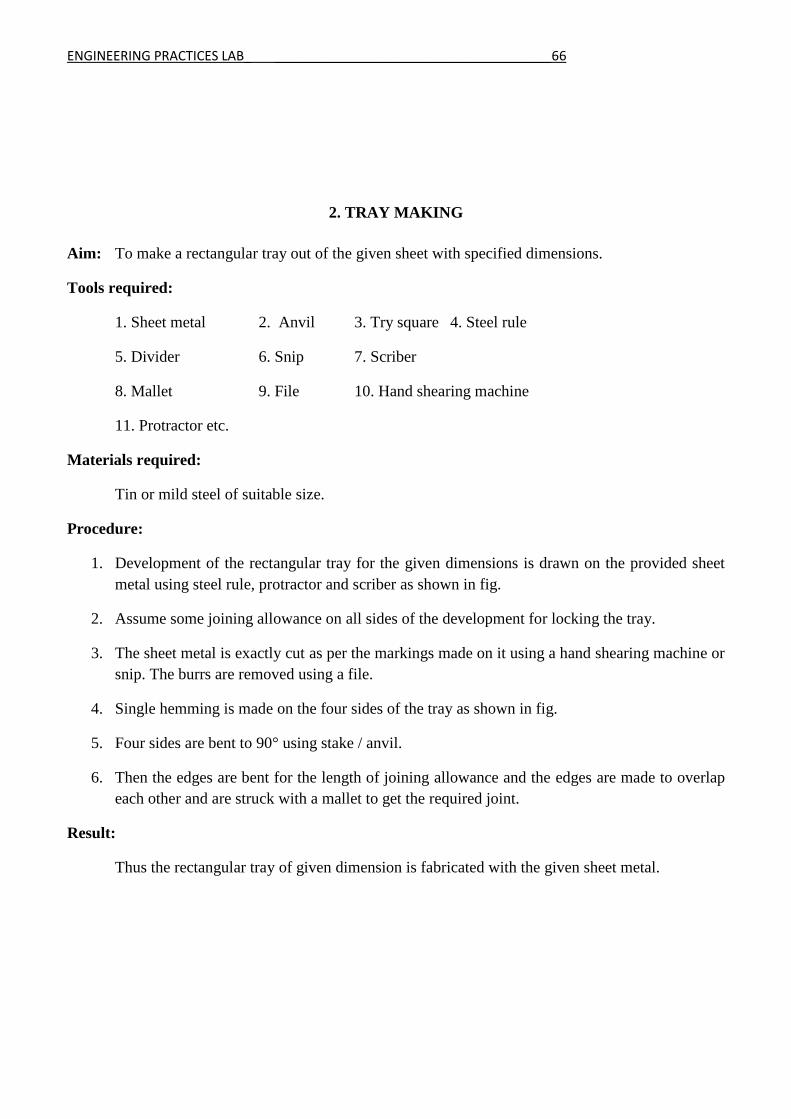
AIR CONDITIONING
An air conditioner is an appliance, system, or mechanism designed to extract heat from an area
using a refrigeration cycle. In construction, a complete system of heating, ventilation, and air
conditioning is referred to as HVAC. Its purpose, in the home or in the car, is to provide comfort
during either hot or cold weather.
Air conditioning system basics and theories
Refrigeration cycle
A simple diagram of the refrigeration cycle contains 1) condensing coil, 2) expansion valve,
3) evaporator coil, 4) compressor. In the refrigeration cycle, a heat pump transfers heat from a
lower temperature heat source into a higher temperature heat sink. Heat would naturally flow in the
opposite direction. This is the most common type of air conditioning. A refrigerator works in much the
same way, as it pumps the heat out of the interior into the room in which it stands.
This cycle takes advantage of the way phase changes work, where latent heat is released at a constant
temperature during a liquid/gas phase change, and where a different pressure of a pure substance
means that it will condense/boil at a different temperature.

ENGINEERING PRACTICES LAB_ ______________________________________71
The most common refrigeration cycle uses an electric motor to drive a compressor. In
an automobile, the compressor is driven by a belt over a pulley, the belt being driven by the engine's
crankshaft (similar to the driving of the pulleys for the alternator, power steering, etc.). Whether in a
car or the house, both use electric fan motors for air circulation. Since evaporation occurs when heat is
absorbed, and condensation occurs when heat is released, air conditioners are designed to use a
compressor to cause pressure changes between two compartments, and actively condense and pump a
refrigerant around.
A refrigerant is pumped into the cooled compartment (the evaporator coil), where the low
pressure and low temperature cause the refrigerant to evaporate into a vapor, taking heat with it. In the
other compartment (the condenser), the refrigerant vapor is compressed and forced through another
heat exchange coil, condensing into a liquid, rejecting the heat previously absorbed from the cooled
space and the cycle repeats to keep the system at the required temperature.

ENGINEERING PRACTICES LAB_ ______________________________________72
TOPIC BEYOND SYLLABUS
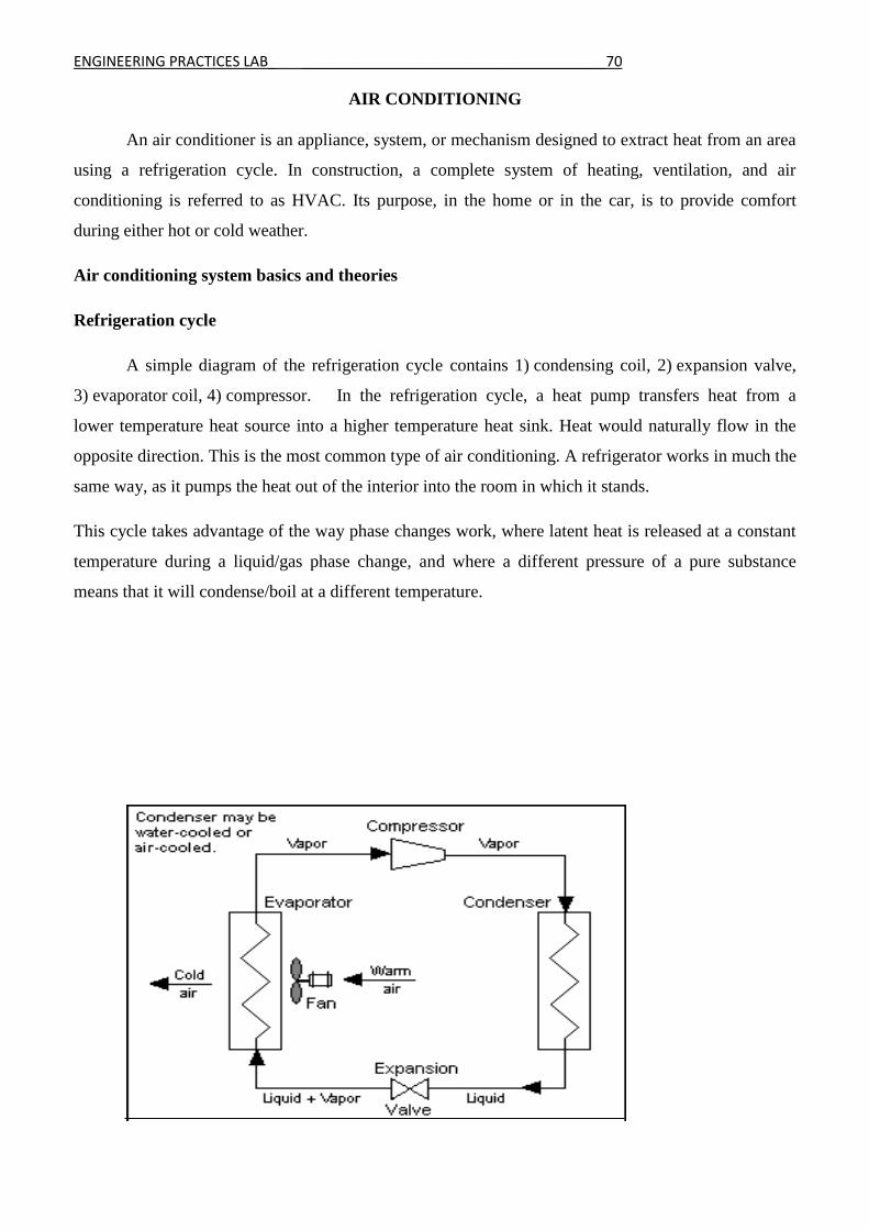
MACHINING A WORKPIECE BY BORING AND INTERNAL THREAD CUTTING OPERATIONS
USING LATHE
Aim:
To perform the boring and internal thread cutting operations on the given work piece as per the given dimensions.
Material Required:
Mild steel rod
Tools Required:
Lathe Scriber
Steel rule Chuck key Vernier caliper Tool post key Cutting tool Internal thread cutting tool
Procedure:
1. The dimension of the given work piece are checked by vernier caliper.
2. The work piece is held in the lathe chuck properly and it is tightened by chuck key.
3. The cutting tool is set in a tool post such that the point of the cutting tool coincides with the lathe axis.
4. The machine is switched ON to remove the work piece at the selected speed.
5. By the giving cross feed and longitudinal feed to the cutting tool the facing and turning operations are done respectively.
6. The speed of the work piece is reduced.
7. The external thread cutting operation is done by using external V thread cutting tool by engaging thread cutting mechanism.
8. The work piece is removed from the chuck and all the dimensions are measured and checked.
ENGINEERING PRACTICES LAB_ ______________________________________73
BORING AND INTERNAL THREAD CUTTING OPERATIONS
ALL DIMENSIONS ARE IN MM
Calculate Time for Boring
Calculate Time for Threading
Gearing ratio= Driver teeth/Driven teeth= TPI to be cut / TPI on lead screw (inch)
Gear ratio= Driver teeth/Driven teeth= 5Pn/127(metric)
Depth of cut = 0.6403Xpitch
Pitch=1/No of TPI
Result: Thus the required size and shape of the given work piece is obtained
ENGINEERING PRACTICES LAB_ ______________________________________74
Welding
A process in which solid materials are joined by the action of interatomic forces. This action results in
a local coalescence or mutual plastic deformation of the parts being joined. Welding can be performed
on objects made of metal or of nonmetallic materials, such as glass, ceramics, and plastics. It is
possible to build up metallic, welded face layers of different thicknesses and different composition by
means of appropriate adjustment of the welding conditions. Under certain conditions, special
equipment makes it possible to use welding for processes essentially the opposite of joining, for
instance, the flame or thermal cutting of metals.
Historical survey. Very simple welding techniques were known as early as 8,000–7,000 B.C. Most of
the welded objects were made of copper; they were preheated and then pressed together. Forge
welding was used to join objects made of copper, bronze, lead, and the noble metals. The parts to be
joined were first molded and preheated, and then a previously melted metal was poured into the joint.
Articles made of iron and iron alloys were obtained by heating the parts to a welding temperature in a
forge and by subsequent hammering. Until the end of the 19th century only these two methods were in
use.
The discovery of the arc discharge by V. V. Petrov in 1802 provided the impetus for new metal-
joining techniques. The first practical methods of arc welding were proposed by N. N. Benardos in
1882 and N. G. Slavianov in 1890. During the early 20th century arc welding gradually became the
preferred industrial method of joining metals. The first attempts to use combustible gases mixed with
oxygen for metal welding and cutting also date from the early 20th century. The first oxygen-acetylene
welding torch was designed by the French engineer E. Fouche, who obtained a German patent for his
torch in 1903. This method was presumably known in Russia by 1905 and was widely used by 1911.
The arc-welding process was further improved, and several versions of the technique appeared,
including submerged arc welding and gas-shielded-arc welding. During the second half of the 20th
century, other sources of energy came into use, including plasmas, electron, photon, and laser beams,
explosives, and ultrasound.
Classification. Modern methods of welding metals can be classified into two large groups: fusion
welding, or liquid-state welding, and pressure welding, or solid-state welding. In fusion welding, the
molten metal of the parts being joined is combined into one mass spontaneously, without applying any
external force, as a result of melting and wetting in the weld zone and of mutual coalescence of the
material. In pressure welding, substantial pressure is applied to join the parts without melting. The
division between these two groups is not always distinct. It is possible, for instance, to weld by first
fusing the parts partially and then pressing the parts together, as is done in resistance welding.
In the above classification, each group includes several methods. Fusion welding includes arc, plasma,
electroslag, gas, and electron-beam welding. Pressure welding includes forge, cold, ultrasonic, friction,
and explosion welding. Other characteristics can also be used as criteria for classification. For
example, the following types of welding can be distinguished according to the type of energy used:
electrical welding (arc, resistance, electroslag, plasma, and induction welding), mechanical welding
(friction, cold, and ultrasonic welding), chemical welding (gas and Thermit welding), and beam-
energy welding (photon-beam, electron-beam, and laser welding).
ENGINEERING PRACTICES LAB_ ______________________________________75
LATHES
The lathe is a machine tool used principally for shaping articles of metal (and
sometimes wood or other materials) by causing the work piece to be held and rotated by the lathe
while a tool bit is advanced into the work causing the cutting action. The basic lathe that was designed
to cut cylindrical metal stock has been developed further to produce screw threads. tapered work.
drilled holes. knurled surfaces, and crankshafts. The typical lathe provides a variety of rotating speeds
and a means to manually and automatically move the cutting tool into the work piece. Machinists and
maintenance shop personnel must be thoroughly familiar with the lathe and its operations to
accomplish the repair and fabrication of needed parts.
LATHE COMPONENTS
Engine lathes all have the same general functional parts, even
though the specific location or shape of a certain part may differ from one manufacturer The bed is the
foundation of the working parts of the lathe to another Ways provide the means for holding the
tailstock and carriage, which slide along the ways, in alignment with the permanently attached
headstock The headstock is located on the operator’s left end of the lathe bed. It contains the main
spindle and oil reservoir and the gearing mechanism for obtaining various spindle speeds and for
transmitting power to the feeding and threading mechanism. The headstock mechanism is driven by
an electric motor connected either to a belt or pulley system or to a geared system. The main spindle is
mounted on bearings in the headstock and is hardened and specially ground to fit different lathe
holding devices. The spindle has a hole through its entire length to accommodate long workplaces.
The hole in the nose of the spindle usually has a standard Morse taper which varies with the size of the
lathe. Centers, collets, drill chucks, tapered shank drills and reamers may be The main feature of its
construction are the ways which are inserted into the spindle. Chucks, drive plates, and faceplates
formed on its upper surface and run the full length of the bed. may be screwed onto the spindle or
clamped onto the spindle nose.
The term "automatic lathe" is still often used in manufacturing
in its earlier sense, referring to automated lathes of non-CNC types. The first kinds of automatic lathes
were mechanically automated ones (whose control is via cams or tracers and pantographs). Thus,
before electronic automation via numerical control, programmable logic controllers, and so on, the

ENGINEERING PRACTICES LAB_ ______________________________________76
"automatic" in the term "automatic machine tool" always referred implicitly to mechanical
automation.
The earliest mechanically automated lathes were geometric lathes. These
included Rose engine lathes and others. In industrial contexts during the Machine Age, the term
"automatic lathe" referred to mechanical screw machines and chuckers (discussed below), of which a
large variety of types, brands, and models were built. Since the maturation of CNC, the implicit
dichotomy of "manual versus automatic" still exists, but because CNC is so ubiquitous, the term
"automatic" has lost some of its distinguishing power. All CNC machine tools are automatic, but
(perhaps therefore) the usage of the machining industries does not routinely call them by that term.
The term "automatic", when it is used at all, still often refers implicitly to cam-operated machines.
Thus a "plain old" 2-axis CNC lathe is not referred to as an "automatic lathe" (even though it is,
literally speaking, automatic). However, within the machining subspecialty of Swiss-type[4] CNC
turning centers, the word "automatic" is often used freely for cam-op and CNC alike (for example,
DMG Mori[5] and Tsugami call their Swiss-type CNCs "automatic lathes").
Small- to medium-sized cam-operated automatic lathes were
(and still are) usually called screw machines or automatic screw machines. These machines work on
parts that (as a rough guide only) are usually less than 80 millimetres (3.1 in) in diameter and less than
300 millimetres (12 in) long. Screw machines almost invariably do bar work, which means that an
entire length of bar stock (anywhere from 1 to 4 m (3.3 to 13.1 ft) in length) passes through the spindle
and is gripped by the chuck (which is usually a collet chuck). As the part is being machined, the entire
length of bar stock is turning with the spindle. When the part is done, it is "parted off" from the bar,
the chuck un-clamps, the bar is fed forward, and the chuck then closes again, ready for the next cycle.
The bar-feeding can happen by various means, including pulling-finger tools that grab the bar and pull
or roller bar feed that pushes the bar from behind.
Larger cam-operated automatic lathes were (and still are) usually
called automatic chucking lathes, automatic lathes, automatic chuckers, automatics, or chuckers. The
"chucker" part of the name comes from the fact that the workpieces are usually discrete blanks, held in
a bin called a "magazine", and each one takes a turn at being chucked (gripped by the machine for
being worked on) and cut. (This is analogous to the way that each round of ammunition in the
magazine of a semi-automatic pistol gets its turn at being chambered.) The blanks are either individual
forgings or castings, or they are pre-sawed pieces of billet. However, some members of this family of
machine tools turn bar work or work on centers (for example, the Fay automatic lathe). Regarding bar
work of large diameter (for example, 150 millimetres (5.9 in) or more), it is merely an academic point
whether it is called "screw machine work" or just "automatic work".