valve control concepts in a constant pressure system with ... · pdf filevalve control...
TRANSCRIPT
21st International Conference on Hydraulics and Pneumatics, June 1st – 3rd 2011, Ostrava, Czech Republic
1
Valve Control Concepts in a Constant Pressure System with an Intermediate Pressure Line
DENGLER, Peter1, GROH, Jonas2 & GEIMER, Marcus3
Karlsruhe Institute of Technology (KIT), Chair of Mobile Machines (Mobima),
Gotthard-Franz-Str. 8, 76131 Karlsruhe, Germany 1 Dipl.-Ing., email: [email protected] 2 Dipl.-Ing., email: [email protected] 3 Prof. Dr.-Ing., email: [email protected]
Abstract: The paper presents a new hydraulic system based on constant pressure with the aim of increasing the efficiency of working hydraulics in mobile machines. The system consists of a high pressure line at constant pressure, a tank pressure line and an additional line with intermediate pressure. Each actuator is supplied by a valve block consisting of two 3/2-switching valves and one proportional valve. The switching valves connect the inlet and the outlet port of the proportional valve to one of the three available pressure levels tank-, intermediate-, and high pressure and allow five different pressure potentials. The proportional valve enables the fine control of the actuator and a constant, load adapted flow. The paper describes furthermore by the use of a simulation model the dynamic effects on the movement of the piston of a hydraulic cylinder when the switching valves are actuated or oscillating loads are applied. Control concepts for a smooth movement of the piston at different operating conditions are shown and discussed concerning their capability for the hydraulic system. Keywords: control, constant, intermediate, pressure, switching
1 Introduction For the actuation of hydraulic cylinders in mobile applications three mainly used systems can be identified: constant flow systems, constant pressure systems and load sensing systems (LS-systems). Constant flow systems generate high power losses when cylinders with low flow demand are actuated. The flow which is not used is conducted directly to the tank and the pressure created by the pump is lost. LS-systems are considered today as one of the most efficient drive system for linear actuators as the pump generates only the flow which is really needed. The pressure is adapted to the highest load pressure and throttle losses are generally kept low. Disadvantageous of LS-systems are high losses at parallel drive of two actuators at different load pressures. As the system pressure is adapted to the maximum load pressure, the pressure difference to the actuator with the lower load pressure must be throttled. Further inconvenient of this system is its incapacity to recover potential or braking energy. Constant pressure systems are one of the simplest hydraulic systems and not very efficient when driven with a constant flow pump. Advanced systems are equipped with a pressure controlled pump and a hydraulic accumulator connected to the main pressure line. In these “Advanced Constant Pressure Systems” [1] secondary controlled hydraulic rotary drives can
2
be operated without system-related losses [2]. These systems already exists at the market [3], [4], even though not in mobile applications yet. One inconvenient of a large scale application of this system is its incompatibility with linear actuators as the high pressure still needed to be throttled to adapt it to the actual load pressure. Concepts of secondary controlled linear actuators are presently in the focus of research [5], [6] but there exists no market ready solution yet. Another approach for the efficient integration of linear actuators in a constant pressure system is the introduction of a supplementary pressure line with a pressure level located between high pressure (HP) and tank pressure (TP) and therefore called “intermediate pressure (IP) line” [7]. By switching the pressure on the inlet and the outlet port of the proportional valve between high, intermediate- and tank pressure losses can be reduced by adapting the applied pressure difference at the piston of the hydraulic cylinder on the actual load. Beside of the switching strategy which is essential to create an energy efficient system the transient behaviour between two different switching states needs to be considered to ensure a good functioning of the system. The main challenge is to design a controller which is able to keep the piston movement constant at different operating conditions only by use of pressure transducers. This allows keeping the costs as low as possible. In this paper the most critical scenarios concerning a smooth movement are shown and approaches how to cope with oscillations of the piston are presented.
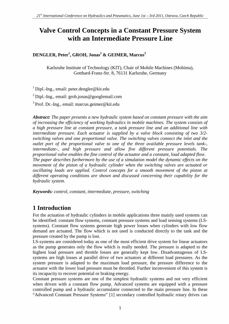
2 Model of the system Each cylinder is supplied by a valve block containing two 3/2-switching valves and one proportional valve. The switching valves connect the inlet port and the outlet port of the proportional valve to one of the three available pressure levels tank-, intermediate- and high pressure which allow therefore four different switching states with different pressure potentials (Figure 1). The proportional valve enables the fine control of the actuator and a constant, load adapted flow. Figure 1 shows the four possible operating modes.
Figure 1 – Different switching states of the system
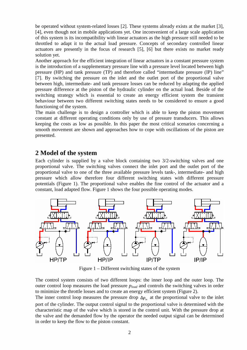
The control system consists of two different loops: the inner loop and the outer loop. The outer control loop measures the load pressure pload and controls the switching valves in order to minimize the throttle losses and to create an energy efficient system (Figure 2). The inner control loop measures the pressure drop inp∆ at the proportional valve to the inlet
port of the cylinder. The output control signal to the proportional valve is determined with the characteristic map of the valve which is stored in the control unit. With the pressure drop at the valve and the demanded flow by the operator the needed output signal can be determined in order to keep the flow to the piston constant.
3
Figure 2 – Relevant variables of the system In order to check the velocity control of the hydraulic piston the system was tested under various operating conditions in a simulation model. The model was created in the simulation program DSHplus [8] and consisted of two switching valves, a proportional valve, a hydraulic piston and a load as shown in Figure 2. In order to identify clearly the dynamic effects of the system the damping of the piston was set up in a way that no resonance effects can superpose the system. The pressures of the high pressure line as well as of the intermediate pressure line were considered as constant.
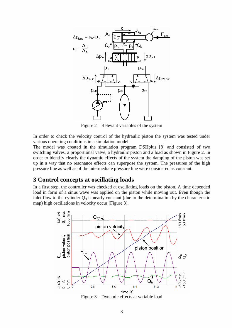
3 Control concepts at oscillating loads In a first step, the controller was checked at oscillating loads on the piston. A time depended load in form of a sinus wave was applied on the piston while moving out. Even though the inlet flow to the cylinder QA is nearly constant (due to the determination by the characteristic map) high oscillations in velocity occur (Figure 3).
Figure 3 – Dynamic effects at variable load
4
The reason for this oscillation is the increasing capacity of the chamber at the piston side when moving out. The velocity of the piston can be described as
( )AHAAA
CpQA
x ,
1 ⋅−= && Equation 1
High pressure changes in the chamber lead at increasing capacities to a considerable oscillation of velocity although the inlet flow is kept constant. Major improvements of the cylinder’s behaviour at oscillating loads could be reached by including the outlet flow of the piston into the controller (Figure 4). As shown in Figure 3 the outlet flow is strongly oscillating. It can be determined by measuring the pressure drop at the proportional valve using the characteristic map of the valve. The difference of the nominal flow (inlet flow) to the determined outlet flow is added to the nominal flow. While the load on the cylinder increases the outlet flow becomes lower as the piston is pushed back. This is detected by the controller, which leads to a higher output signal to the valve enabling a stabilization of the piston’s velocity.
Figure 4 – Controller using inlet and outlet flow of the cylinder
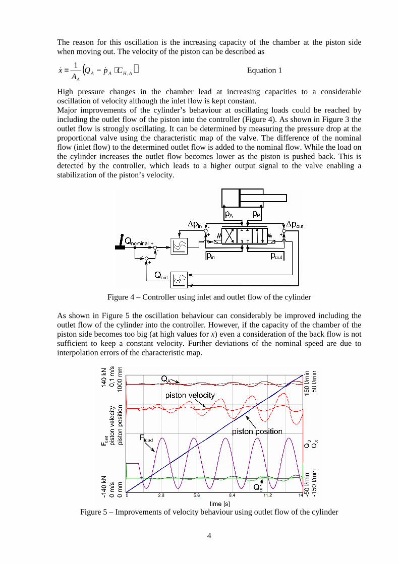
As shown in Figure 5 the oscillation behaviour can considerably be improved including the outlet flow of the cylinder into the controller. However, if the capacity of the chamber of the piston side becomes too big (at high values for x) even a consideration of the back flow is not sufficient to keep a constant velocity. Further deviations of the nominal speed are due to interpolation errors of the characteristic map.
Figure 5 – Improvements of velocity behaviour using outlet flow of the cylinder
5
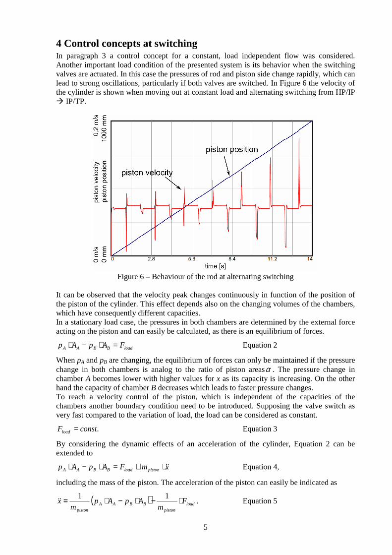
4 Control concepts at switching In paragraph 3 a control concept for a constant, load independent flow was considered. Another important load condition of the presented system is its behavior when the switching valves are actuated. In this case the pressures of rod and piston side change rapidly, which can lead to strong oscillations, particularly if both valves are switched. In Figure 6 the velocity of the cylinder is shown when moving out at constant load and alternating switching from HP/IP � IP/TP.
Figure 6 – Behaviour of the rod at alternating switching
It can be observed that the velocity peak changes continuously in function of the position of the piston of the cylinder. This effect depends also on the changing volumes of the chambers, which have consequently different capacities. In a stationary load case, the pressures in both chambers are determined by the external force acting on the piston and can easily be calculated, as there is an equilibrium of forces.
loadBBAA FApAp =⋅−⋅ Equation 2
When pA and pB are changing, the equilibrium of forces can only be maintained if the pressure change in both chambers is analog to the ratio of piston areasα . The pressure change in chamber A becomes lower with higher values for x as its capacity is increasing. On the other hand the capacity of chamber B decreases which leads to faster pressure changes. To reach a velocity control of the piston, which is independent of the capacities of the chambers another boundary condition need to be introduced. Supposing the valve switch as very fast compared to the variation of load, the load can be considered as constant.
.constFload = Equation 3
By considering the dynamic effects of an acceleration of the cylinder, Equation 2 can be extended to
xmFApAp pistonloadBBAA &&⋅+=⋅−⋅ Equation 4,
including the mass of the piston. The acceleration of the piston can easily be indicated as
( ) loadpiston
BBAApiston
Fm
ApApm
x ⋅−⋅−⋅= 11&& . Equation 5
6
The mass mpiston can experimentally be determined, as it depends also on all connected mechanic parts connected to it. The deviation of the velocity, i.e. the acceleration, can be used now to adjust directly the output signal of the controller. To determine the deviation of velocity Equation 4 needs to be integrated.
( )( )dtFApApm
x loadBBAApiston
∫ −⋅−⋅= 1& Equation 6
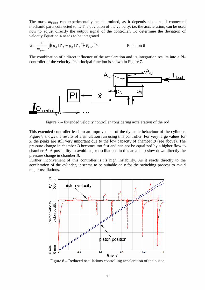
The combination of a direct influence of the acceleration and its integration results into a PI-controller of the velocity. Its principal function is shown in Figure 7.
Figure 7 – Extended velocity controller considering acceleration of the rod
This extended controller leads to an improvement of the dynamic behaviour of the cylinder. Figure 8 shows the results of a simulation run using this controller. For very large values for x, the peaks are still very important due to the low capacity of chamber B (see above). The pressure change in chamber B becomes too fast and can not be equalized by a higher flow to chamber A. A possibility to avoid major oscillations in this area is to slow down directly the pressure change in chamber B. Further inconvenient of this controller is its high instability. As it reacts directly to the acceleration of the cylinder, it seems to be suitable only for the switching process to avoid major oscillations.
Figure 8 – Reduced oscillations controlling acceleration of the piston

7
5 Conclusion To create an energy saving hydraulic system allowing switching between different pressure levels the smooth movement of the hydraulic cylinder for different operation conditions needs to be shown. In a stationary load case the output signal to the proportional valve can directly be determined using the characteristic map of the valve. For a dynamic consideration this approach is not sufficient. For this reason two principal scenarios where presented: a variation of load at the piston and a variation of pressure in the chambers of the cylinder while switching from one pressure level to another. Both scenarios lead to high oscillations. The first scenario could significantly be improved by considering inlet and outlet flow of the cylinder. For the second scenario the acceleration of the cylinder is included into the controller beside to the velocity of the cylinder. It has shown a good improvement concerning oscillations. For further improvements a slower switching between TP and IP on the outlet side of the cylinder need to be realized. Switching valves which allows a quasi proportional change between TP and IP could allow a slower pressure change by doing so. Another solution could be an alternating switching between TP and IP allowing a step-wise pressure change in chamber B. The presented control concepts represent the first results of an analysis of the dynamic effects on a hydraulic cylinder when driven in a constant pressure system with an intermediate pressure line. Further work need to be done to create a controller which combines both approaches and which is able to maintain a continuous movement of the cylinder at various load scenarios.
6 Acknowledgments The project was performed by the Chair of Mobile Machines (Mobima) at the Karlsruhe Institute of Technology (KIT) in cooperation with ARGO-HYTOS GmbH, FLUIDON GmbH and Hermann Paus Maschinenfabrik GmbH. The project is financed by the Federal Ministry of Education and Research (BMBF) and supervised by the German Aerospace Center (DLR). The authors thank the BMBF and the DLR for the support of this project.
7 References [1] DREHER, T. 2010. The Capability of Hydraulic Constant Pressure Systems with a Focus
on Mobile Machines, 6th FPNI – PhD Symposium, West Lafayette 2010, proceedings p. 579-588.
[2] HAAS, H.-J. 1989. Sekundärgeregelte hydrostatische Antriebe im Drehzahl- und Drehwinkelregelkreis, PhD thesis, RWTH Aachen, 1989
[3] Data Sheet RD92056/10.04. Secondary control with A4VSO axial piston units, 2010, Bosch Rexroth, available at www.boschrexroth.com
[4] FISCHER, H. STEIGERWALD, T. & GODZIG, M. 2010. Hydraulic Systems for Deep-Sea Applications, 7th International Fluid Power Conference, Aachen, 2010.
[5] LINJAMA et. al. 2009. Secondary Controlled Multi Chamber Cylinder, 11th Scandinavian International Conference on Fluid Power, Linköping, 2009.
[6] BISHOP, E. D. 2009. Digital Hydraulic Transformer – Approaching theoretical Perfection in Hydraulic Drive Efficiency, 11th Scandinavian International Conference on Fluid Power, Linköping, 2009.
[7] DENGLER, P., GEIMER, M. 2011. Zwischen den Drücken lesen – Effizienzsteigerung durch ein Konstantdrucksystem mit Zwischendruckleitung, O+P 1-2, 2011, p. 24-27
[8] DSHplus Manuals 2001.,FLUIDON GmbH, Aachen