valve unit quick die change systems operation panel … · mf0010 mr0400 mr0600 mr0800 mr0270 ml04...
TRANSCRIPT
AIR CLAMP SYSTEMSeries
QUICK MOLD CHANGE SYSTEMS
AIR CLAMP
VALVE UNIT
OPERATION PANELCONTROL UNIT
QUICK DIE CHANGE SYSTEMS
KOSMEK DIECAST CLAMPING SYSTEMS
KOSMEK WORK CLAMPING SYSTEMS
7MPa35MPa
2000. 1. First 1 C2012. 9. 7th 1 RyPrinted in Japan
CAT.NO.HZ-07-02
http://www.kosmek.co.jp
JQA-QMA10823KOSMEK HEAD OFFICE
HEAD OFFICE
BRANCH OFFICE (U.S.A.)
THAILAND REPRESENTATIVE OFFICE
1-5, 2-Chome, Murotani, Nishi-ku, Kobe 651-2241TEL.+81-78-991-5115 FAX.+81-78-991-8787
KOSMEK (U.S.A.) LTD.1441 Branding Avenue, Suite 110, Downers Grove, IL 60515 USATEL.+1-630-241-3465 FAX.+1-630-241-3834
67 Soi 58, RAMA 9 Rd., Suanluang, Suanluang, Bangkok 10250TEL.+66-2-715-3450 FAX.+66-2-715-3453
● FOR FURTHER INFORMATION ON UNLISTED SPECIFICATIONS AND SIZES, PLEASE CALL US.
● SPECIFICATIONS IN THIS LEAFLET ARE SUBJECT TO CHANGE WITHOUT NOTICE.
1 2
VERTICAL MOLD CHANGE SYSTEM
VERTICAL INJECTION MOLDING MACHINE
HORIZONTAL MOLD CHANGE SYSTEM
MOLD
CLAMPMOLDSUPPORT BLOCK
STATIONARY PLATEN
MOVABLE PLATEN
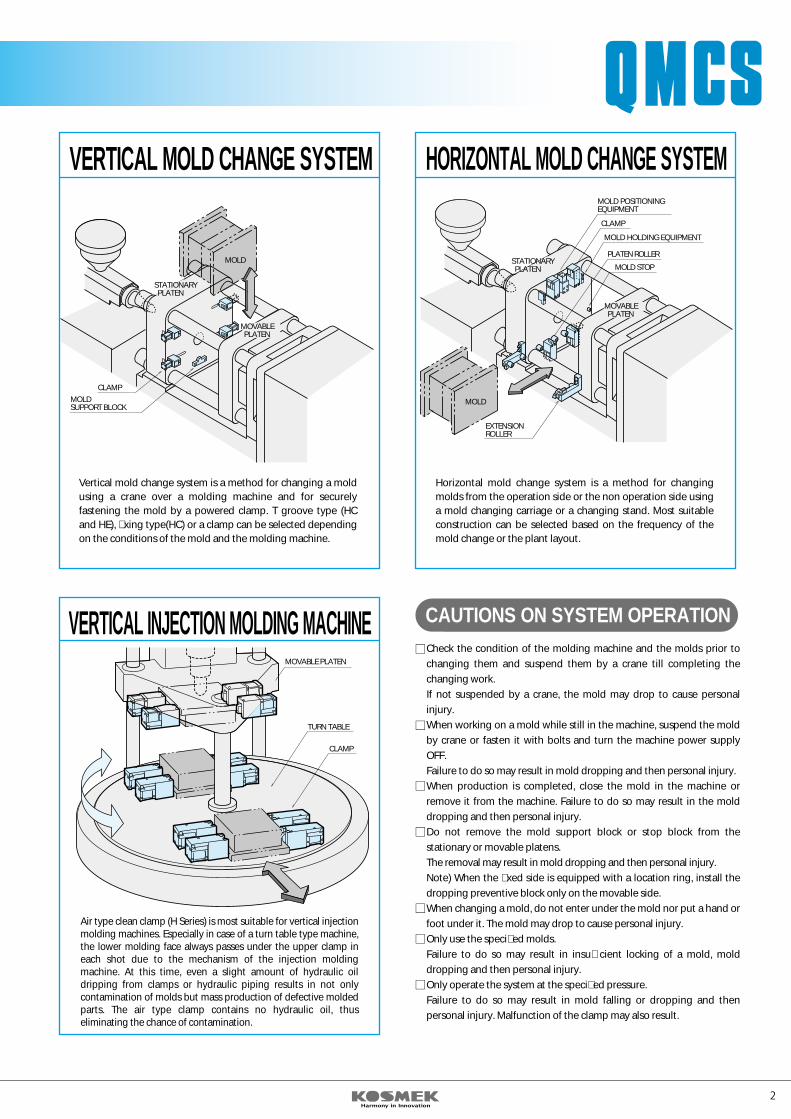
Vertical mold change system is a method for changing a mold using a crane over a molding machine and for securely fastening the mold by a powered clamp. T groove type (HC and HE), �xing type(HC) or a clamp can be selected depending on the conditions of the mold and the molding machine.
EXTENSIONROLLER
MOLD POSITIONINGEQUIPMENT
CLAMP
MOLD HOLDING EQUIPMENT
PLATEN ROLLER
MOLD STOP
Horizontal mold change system is a method for changing molds from the operation side or the non operation side using a mold changing carriage or a changing stand. Most suitable construction can be selected based on the frequency of the mold change or the plant layout.
STATIONARY PLATEN
MOVABLE PLATEN
MOLD
MOVABLE PLATEN
TURN TABLE
CLAMP
Air type clean clamp (H Series) is most suitable for vertical injection molding machines. Especially in case of a turn table type machine, the lower molding face always passes under the upper clamp in each shot due to the mechanism of the injection molding machine. At this time, even a slight amount of hydraulic oil dripping from clamps or hydraulic piping results in not only contamination of molds but mass production of defective molded parts. The air type clamp contains no hydraulic oil, thus eliminating the chance of contamination.
CAUTIONS ON SYSTEM OPERATIONCheck the condition of the molding machine and the molds prior to changing them and suspend them by a crane till completing the changing work.If not suspended by a crane, the mold may drop to cause personal injury.When working on a mold while still in the machine, suspend the mold by crane or fasten it with bolts and turn the machine power supply OFF.Failure to do so may result in mold dropping and then personal injury.When production is completed, close the mold in the machine or remove it from the machine. Failure to do so may result in the mold dropping and then personal injury.Do not remove the mold support block or stop block from the stationary or movable platens.The removal may result in mold dropping and then personal injury.Note) When the �xed side is equipped with a location ring, install the dropping preventive block only on the movable side.When changing a mold, do not enter under the mold nor put a hand or foot under it. The mold may drop to cause personal injury.Only use the speci�ed molds.Failure to do so may result in insu�cient locking of a mold, mold dropping and then personal injury.Only operate the system at the speci�ed pressure.Failure to do so may result in mold falling or dropping and then personal injury. Malfunction of the clamp may also result.
KOSMEKQUICK MOLD CHANGE SYSTEMSHC/HB/HE ADVANTAGES OF AIR CLAMP SYSTEM
Power source is general compressed air.The air type clamp system eliminates the possibility of contamination around the clamp due to oil leakage or dripping.Piping work is easy because the circuit consists of air lines.Fire hazard by use/or storage of hydraulic oil is eliminated.Excellent for electric machines, no hydraulic unit is required.Maintenance is easy as there is no oil mess.This system is interchangeable with our hydraulic type clamp(GWA type)as the mounting bolt pitch is identical. Endurance at high temperature is improved because the working pressure of this system is lower than that of the hydraulic type.Overall system costs are less than hydraulic systems.
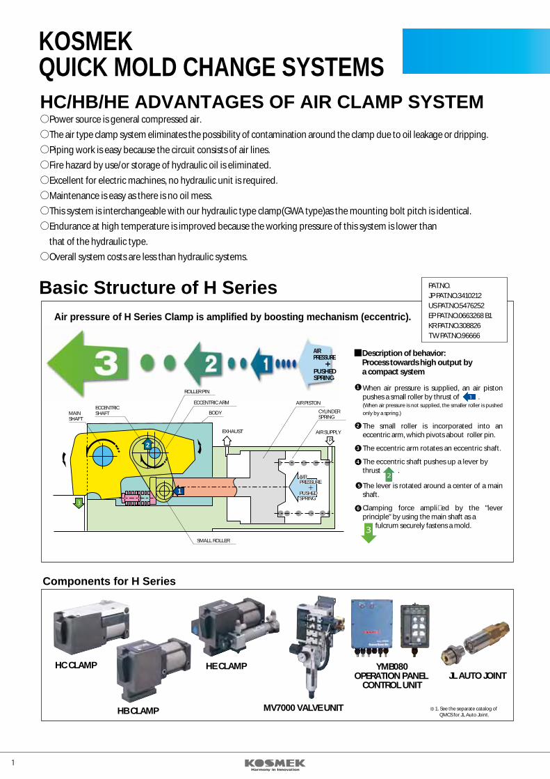
Basic Structure of H SeriesAir pressure of H Series Clamp is amplified by boosting mechanism (eccentric). PAT. PEND
1
2
3
4
6
5
1
2
3
AIR SUPPLYEXHAUST
CYLINDERSPRING
BODYECCENTRICSHAFT
AIR PISTONECCENTRIC ARM
MAINSHAFT
ROLLER PIN
SMALL ROLLER
P
1
3
2
AIRPRESSUREAIRPRESSURE
PUSHEDSPRINGPUSHEDSPRING
When air pressure is supplied, an air piston pushes a small roller by thrust of . (When air pressure is not supplied, the smaller roller is pushed only by a spring.)
The small roller is incorporated into an eccentric arm, which pivots about roller pin.
The eccentric arm rotates an eccentric shaft.
The eccentric shaft pushes up a lever bythrust .
The lever is rotated around a center of a main shaft.
Clamping force ampli�ed by the "lever principle" by using the main shaft as a fulcrum securely fastens a mold.
AIRPRESSURE
PUSHEDSPRING
Description of behavior:Process towards high output bya compact system
PAT.NO.JP PAT.NO.3410212US PAT.NO.5476252EP PAT.NO.0663268 B1KR PAT.NO.308826TW PAT.NO.96666
Components for H Series
HC CLAMP
HB CLAMP
HE CLAMP
MV7000 VALVE UNIT
YMB080OPERATION PANEL
CONTROL UNITJL AUTO JOINT
1. See the separate catalog of QMCS for JL Auto Joint.
1 2
VERTICAL MOLD CHANGE SYSTEM
VERTICAL INJECTION MOLDING MACHINE
HORIZONTAL MOLD CHANGE SYSTEM
MOLD
CLAMPMOLDSUPPORT BLOCK
STATIONARY PLATEN
MOVABLE PLATEN
Vertical mold change system is a method for changing a mold using a crane over a molding machine and for securely fastening the mold by a powered clamp. T groove type (HC and HE), �xing type(HC) or a clamp can be selected depending on the conditions of the mold and the molding machine.
EXTENSIONROLLER
MOLD POSITIONINGEQUIPMENT
CLAMP
MOLD HOLDING EQUIPMENT
PLATEN ROLLER
MOLD STOP
Horizontal mold change system is a method for changing molds from the operation side or the non operation side using a mold changing carriage or a changing stand. Most suitable construction can be selected based on the frequency of the mold change or the plant layout.
STATIONARY PLATEN
MOVABLE PLATEN
MOLD
MOVABLE PLATEN
TURN TABLE
CLAMP
Air type clean clamp (H Series) is most suitable for vertical injection molding machines. Especially in case of a turn table type machine, the lower molding face always passes under the upper clamp in each shot due to the mechanism of the injection molding machine. At this time, even a slight amount of hydraulic oil dripping from clamps or hydraulic piping results in not only contamination of molds but mass production of defective molded parts. The air type clamp contains no hydraulic oil, thus eliminating the chance of contamination.
CAUTIONS ON SYSTEM OPERATIONCheck the condition of the molding machine and the molds prior to changing them and suspend them by a crane till completing the changing work.If not suspended by a crane, the mold may drop to cause personal injury.When working on a mold while still in the machine, suspend the mold by crane or fasten it with bolts and turn the machine power supply OFF.Failure to do so may result in mold dropping and then personal injury.When production is completed, close the mold in the machine or remove it from the machine. Failure to do so may result in the mold dropping and then personal injury.Do not remove the mold support block or stop block from the stationary or movable platens.The removal may result in mold dropping and then personal injury.Note) When the �xed side is equipped with a location ring, install the dropping preventive block only on the movable side.When changing a mold, do not enter under the mold nor put a hand or foot under it. The mold may drop to cause personal injury.Only use the speci�ed molds.Failure to do so may result in insu�cient locking of a mold, mold dropping and then personal injury.Only operate the system at the speci�ed pressure.Failure to do so may result in mold falling or dropping and then personal injury. Malfunction of the clamp may also result.
KOSMEKQUICK MOLD CHANGE SYSTEMSHC/HB/HE ADVANTAGES OF AIR CLAMP SYSTEM
Power source is general compressed air.The air type clamp system eliminates the possibility of contamination around the clamp due to oil leakage or dripping.Piping work is easy because the circuit consists of air lines.Fire hazard by use/or storage of hydraulic oil is eliminated.Excellent for electric machines, no hydraulic unit is required.Maintenance is easy as there is no oil mess.This system is interchangeable with our hydraulic type clamp(GWA type)as the mounting bolt pitch is identical. Endurance at high temperature is improved because the working pressure of this system is lower than that of the hydraulic type.Overall system costs are less than hydraulic systems.
Basic Structure of H SeriesAir pressure of H Series Clamp is amplified by boosting mechanism (eccentric). PAT. PEND
1
2
3
4
6
5
1
2
3
AIR SUPPLYEXHAUST
CYLINDERSPRING
BODYECCENTRICSHAFT
AIR PISTONECCENTRIC ARM
MAINSHAFT
ROLLER PIN
SMALL ROLLER
P
1
3
2
AIRPRESSUREAIRPRESSURE
PUSHEDSPRINGPUSHEDSPRING
When air pressure is supplied, an air piston pushes a small roller by thrust of . (When air pressure is not supplied, the smaller roller is pushed only by a spring.)
The small roller is incorporated into an eccentric arm, which pivots about roller pin.
The eccentric arm rotates an eccentric shaft.
The eccentric shaft pushes up a lever bythrust .
The lever is rotated around a center of a main shaft.
Clamping force ampli�ed by the "lever principle" by using the main shaft as a fulcrum securely fastens a mold.
AIRPRESSURE
PUSHEDSPRING
Description of behavior:Process towards high output bya compact system
PAT.NO.JP PAT.NO.3410212US PAT.NO.5476252EP PAT.NO.0663268 B1KR PAT.NO.308826TW PAT.NO.96666
Components for H Series
HC CLAMP
HB CLAMP
HE CLAMP
MV7000 VALVE UNIT
YMB080OPERATION PANEL
CONTROL UNITJL AUTO JOINT
1. See the separate catalog of QMCS for JL Auto Joint.
3 4
BA
BA
HC CLAMPMOLD STOP(MM)
MOLD SAFETYRETAINER (MF)
MOLD POSITIONINGDEVICE(MP)
INNER PANELROLLER(MR)
PRE-ROLLER (ML)
MOLD CHANGECARRIAGE
FIXED PLATEN
MS2030-5Limit switch
type
MS2041-5Proximity
switch type
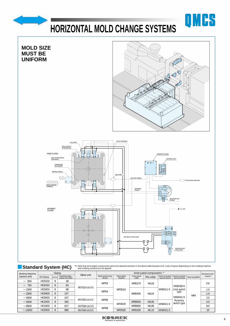
MOLD SIZEMUST BEUNIFORM
RELAY BOX
ELECTRIC WIRING
AIR PIPINGFOR MP
AIR VALVE UNITFOR MP
TO MOLDING MACHINE
AIR
AIR VALVE UNITFOR CLAMP
AIR CIRCUIT FOR CLAMP
MOVABLEPLATEN
Standard System (HC)
HC0102
HC0162
HC0253
HC0403
HC0633
HC1003
HC1603
HC2503
8
8
8
8
8
8
8
8
39
63
98
157
247
392
627
980
MP03
MF0020
MF0030 MR1000 ML10
MF0010
MR0400
MR0600
MR0800
MR0270
ML04
ML06
ML08
ML02
MS4011-5
MS4021-5
MS4031-5
MP04
MP06
MP08
MM
0.6
1.0
1.52.5
4.5
8.0
15
MV7010-UU-5-5
MV7020-UU-5-5
MV7030-UU-5-5
MV7040-UU-5-5
Inner panel componentsPre-roller
ClampValve unitMolding Machine
Capacity (kN) HC Clamp Quantity Fixed/Movableclamp force (kN)
Mold positioningdevice
Mold safetyretainer
inner panelroller
Detection of excessivelylarge mold thickness
Detection of excessivelysmall mold thickness Mold stop(MM)
Standard moldmass t
Note that some platen components cannot be selected as shown in the above table because of di�culty of layout depending on the molding machine and molding conditions to be applied.
500
750
1500
2500
3500
5500
8500
13000
HORIZONTAL MOLD CHANGE SYSTEMS
OPERATION PANEL
CONTROL UNIT
OPERATION PANEL
CONTROL UNIT
OPERATION PANEL
CONTROL UNIT
FIXEDPLATEN
MOVABLEPLATEN
GUIDE BLOCK (MG)
HC CLAMP
BA
BA
BA
BA
BA
BA
FORUNIFORMWIDTHMOLDS
FORVARIABLEWIDTHMOLDS
MOLDSUPPORT BLOCK (MH)
RELAY BOX
TO MOLDING MACHINE
AIRELECTRIC WIRING
ELECTRIC WIRING
AIR VALVE UNIT
FIXEDPLATEN
MOVABLEPLATEN
T-SLOT PLATE
HE CLAMP
RELAY BOX
MOLD SUPPORT BLOCK (MH)
TO MOLDING MACHINE
AIR
AIR VALVE UNIT
MOLD SAFETY BLOCK
500
750
1500
2500
3500
5500
8500
13000
HC0102
HC0162
HC0253
HC0403
HC0633
HC1003
HC1603
HC2503
HB0101
HB0161
HB0252
HB0402
HB0632
HB1002
HB1602
8
8
8
8
8
8
8
8
39
63
98
157
247
392
627
980
MV7010-UU-5-5
(MV7010-UUTT-5-5)
MV7020-UU-5-5(MV7020-UUTT-5-5)
MV7030-UU-5-5(MV7030-UUTT-5-5)
MV7040-UU-5-5
MH03 MJ0010
MJ0020
MJ0030MJ0040
MJ0050
MH04
MH06
MH08
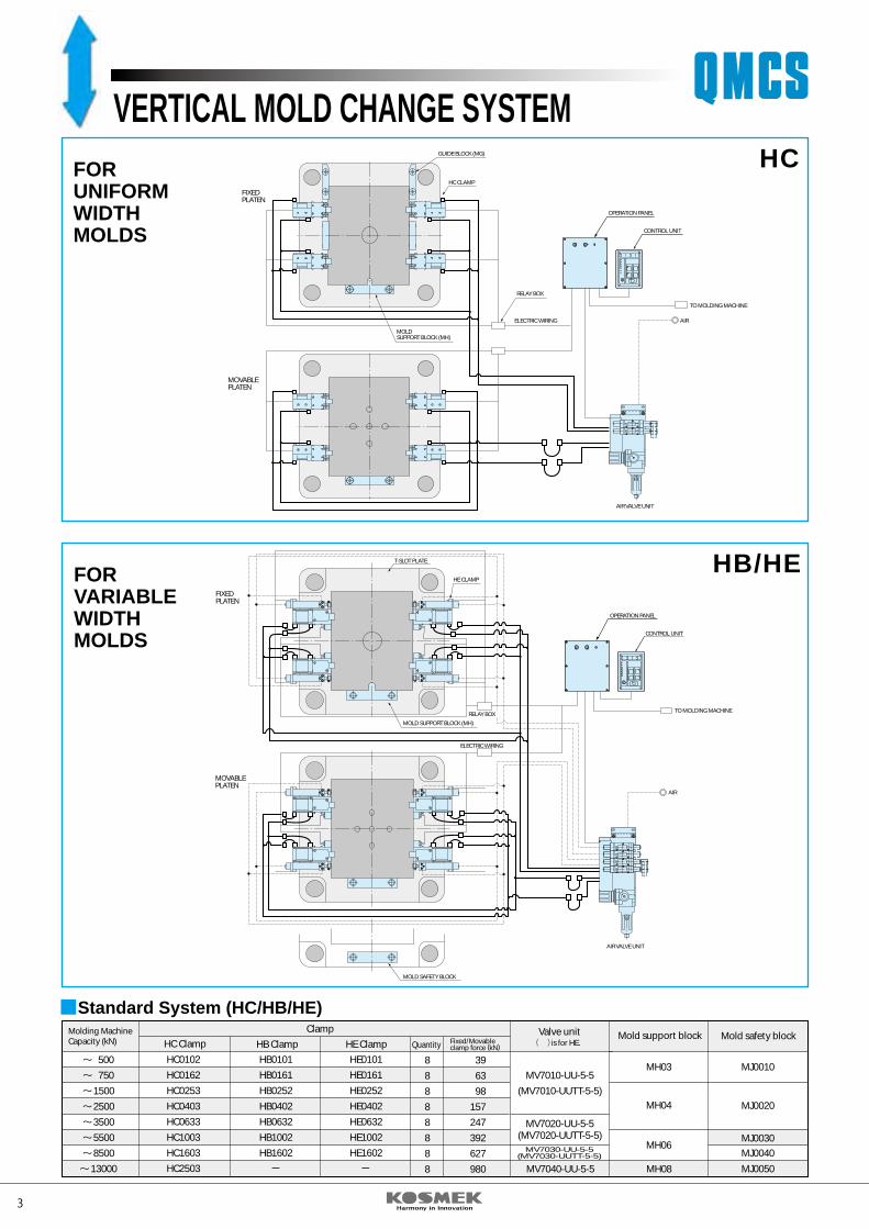
Valve unit Mold support block Mold safety block Clamp
HC Clamp HB ClampHE0101
HE0161
HE0252
HE0402
HE0632
HE1002
HE1602
HE Clamp Quantity Fixed/Movableclamp force (kN)
Molding MachineCapacity (kN) is for HE.
Standard System (HC/HB/HE)
HC
HB/HE
VERTICAL MOLD CHANGE SYSTEM
3 4
BA
BA
HC CLAMPMOLD STOP(MM)
MOLD SAFETYRETAINER (MF)
MOLD POSITIONINGDEVICE(MP)
INNER PANELROLLER(MR)
PRE-ROLLER (ML)
MOLD CHANGECARRIAGE
FIXED PLATEN
MS2030-5Limit switch
type
MS2041-5Proximity
switch type
MOLD SIZEMUST BEUNIFORM
RELAY BOX
ELECTRIC WIRING
AIR PIPINGFOR MP
AIR VALVE UNITFOR MP
TO MOLDING MACHINE
AIR
AIR VALVE UNITFOR CLAMP
AIR CIRCUIT FOR CLAMP
MOVABLEPLATEN
Standard System (HC)
HC0102
HC0162
HC0253
HC0403
HC0633
HC1003
HC1603
HC2503
8
8
8
8
8
8
8
8
39
63
98
157
247
392
627
980
MP03
MF0020
MF0030 MR1000 ML10
MF0010
MR0400
MR0600
MR0800
MR0270
ML04
ML06
ML08
ML02
MS4011-5
MS4021-5
MS4031-5
MP04
MP06
MP08
MM
0.6
1.0
1.52.5
4.5
8.0
15
MV7010-UU-5-5
MV7020-UU-5-5
MV7030-UU-5-5
MV7040-UU-5-5
Inner panel componentsPre-roller
ClampValve unitMolding Machine
Capacity (kN) HC Clamp Quantity Fixed/Movableclamp force (kN)
Mold positioningdevice
Mold safetyretainer
inner panelroller
Detection of excessivelylarge mold thickness
Detection of excessivelysmall mold thickness Mold stop(MM)
Standard moldmass t
Note that some platen components cannot be selected as shown in the above table because of di�culty of layout depending on the molding machine and molding conditions to be applied.
500
750
1500
2500
3500
5500
8500
13000
HORIZONTAL MOLD CHANGE SYSTEMS
OPERATION PANEL
CONTROL UNIT
OPERATION PANEL
CONTROL UNIT
OPERATION PANEL
CONTROL UNIT
FIXEDPLATEN
MOVABLEPLATEN
GUIDE BLOCK (MG)
HC CLAMP
BA
BA
BA
BA
BA
BA
FORUNIFORMWIDTHMOLDS
FORVARIABLEWIDTHMOLDS
MOLDSUPPORT BLOCK (MH)
RELAY BOX
TO MOLDING MACHINE
AIRELECTRIC WIRING
ELECTRIC WIRING
AIR VALVE UNIT
FIXEDPLATEN
MOVABLEPLATEN
T-SLOT PLATE
HE CLAMP
RELAY BOX
MOLD SUPPORT BLOCK (MH)
TO MOLDING MACHINE
AIR
AIR VALVE UNIT
MOLD SAFETY BLOCK
500
750
1500
2500
3500
5500
8500
13000
HC0102
HC0162
HC0253
HC0403
HC0633
HC1003
HC1603
HC2503
HB0101
HB0161
HB0252
HB0402
HB0632
HB1002
HB1602
8
8
8
8
8
8
8
8
39
63
98
157
247
392
627
980
MV7010-UU-5-5
(MV7010-UUTT-5-5)
MV7020-UU-5-5(MV7020-UUTT-5-5)
MV7030-UU-5-5(MV7030-UUTT-5-5)
MV7040-UU-5-5
MH03 MJ0010
MJ0020
MJ0030MJ0040
MJ0050
MH04
MH06
MH08
Valve unit Mold support block Mold safety block Clamp
HC Clamp HB ClampHE0101
HE0161
HE0252
HE0402
HE0632
HE1002
HE1602
HE Clamp Quantity Fixed/Movableclamp force (kN)
Molding MachineCapacity (kN) is for HE.
Standard System (HC/HB/HE)
HC
HB/HE
VERTICAL MOLD CHANGE SYSTEM
5 6
AIRCLAMP
HC 010 2
Design No.
20 R V
Model code
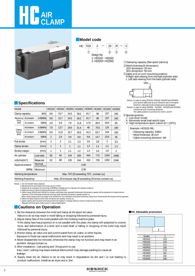
Example HC0102-30LClamping capacity 9.8kNMold thickness 30 mm Cable mounting direction left
Cable
Clamping capacity (See speci�cations)Mold thickness (h dimension)20:h dimension 20 mm 50:h dimension 50 mm Cable and air port mounting positionR :Right side viewing from the back (cylinder side)L :Left side viewing from the back (cylinder side)
Special symbolsJ : Low lever modelK : Extremely small load switch typeV : High temperature speci�cation (0~120℃)
Model
Clamp capacity
Full stroke
Clamp stroke
Stroke margin
Air cylinder
volume(cm3)
Supply air pressure
(MPa)
Working temperature
Working frequency
(kN)
(mm)
(mm)
(mm)
Lock side
Release side
Minimum
0.39MPa
0MPa
0.49MPa
0.39MPa
0MPa
HC0102
9.8
9.8
2.9
7.8
6.9
2
2
1
1
56
52
HC0162
15.7
15.7
5.9
13.7
11.8
2.9
2
1
1
94
88
HC0253
24.5
24.5
7.8
19.6
16.7
4.9
2.1
1
1.1
144
135
HC0403
39.2
39.2
11.8
31.4
26.5
6.9
2.3
1.1
1.2
259
244
HC0633
61.7
61.7
17.6
48
41.2
9.8
2.6
1.2
1.4
444
416
HC1003
98
98
26.5
75.5
63.7
14.7
2.8
1.2
1.6
773
729
157
157
40.9
124
104
23.5
3
1.2
1.8
1334
1262
HC1603
Retainingforce(kN)
Clampforce(kN)
Normal(recommended)
Air pressure
Air pressure
Air pressure
Air pressure
Air pressure
Specifications
0.49
0.39
Max. 70 (If exceeding 70 , contact us.)
Max. 20 times per day (If exceeding 20 times, contact us.)
Notes) 1. Do not exceed clamp capacity.2. Retaining force and clamp force may vary by 10%.3. Supply air at a pressure of more than 0.39 MPa to release port to maintain the release condition.4. Keep accuracy of clamp thickness (dimension h) at 0.3mm.5. When using HC0102 and HC0162 for thicker mold plate than standard thickness (h-dimension), spacer will be attached on clamp bottom. However, if the mold plate thickness is thinner than standard dimension, please contact us. When using clamps which are larger than HC0253 for non-standard mold plate thickness, clamp lever thickness (M-dimension) will be adjusted.6. When the speci�cations other than the above are needed, contact us.7. Speci�cations and contents of this document are subject to change without notice to improve the products. Request technical speci�cations prior to actual application.
HC2503
245
245
65
190
160
35
3.3
1.3
2
2468
2346
1. Set the clearance between the mold and clamp at the speci�ed value.Failure to do so may result in mold falling or dropping followed by personal injury.
2. Adjust clamp face of the mold parallel with the molding machine plate.If the clamp face has projection or is not parallel with the plate, the clamp will subjected to uneven force, and deformation of a lever and a main shaft or falling or dropping of the mold may result followed by personal injury.
3. Protect clamp, air valve unit and control panel from oil, water, or other liquids. Exposure to these can cause malfunction and may result in an accident. 4. Never disassemble nor remodel, otherwise the clamp may not function and may result in an accident. Always contact us.5. After installation, �ush piping and �ttings prior to use. Insu�cient �ushing may leave residual debris which may damage packings to cause air leakage. 6. Supply clean dry air. Failure to do so may result in degradation by dirt and / or rust leading to
product malfunction. Install an air dryer and a �lter.
Cautions on Operation
ModelHC0102HC0162HC0253HC0403HC0633HC1003HC1603HC2503
113119111156179167152190
HC Allowable protrusion
Note1) In case of using HC0102, HC0162, HC0253 and HC0403, prox.switch cable and air port direction are in the same direction. Opposite body surface ports are plugged.Note2) In case of using HC0633、HC1003、HC1603 and HC2503, it shows air port mounting direction. The cable position is common for both L and R.
2 : HC0102・HC01623 : HC0253~HC2503
LOCKCONFIRMATIONSWITCH
RELEASECONFIRMATIONSWITCH
CLAMP POINT
FULL
STR
OKE
CLA
MP
STRO
KE
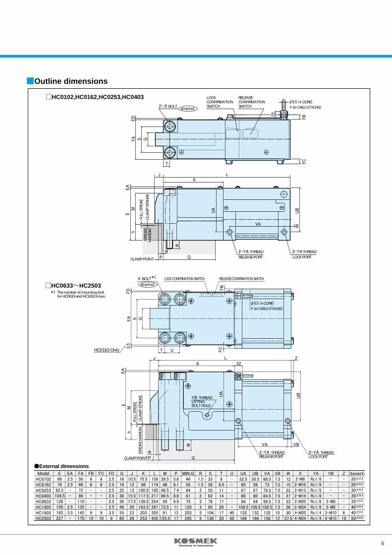
Outline dimensions
HC0102,HC0162,HC0253,HC0403BOLT
HC0633~HC2503*1. The number of mounting bolt for HC0633 and HC1003 is two.
THREADRELEASE PORT
THREADLOCK PORT
External dimensions
attached
attached
THC0163 Only U
LK
YB THREADLIFTINGBOLT HOLE
22
VA
2-YA THREADRELEASE PORT
2-YA 2-YA
2-YA THREADLOCK PORT
YARc1/8Rc1/8Rc1/8Rc1/8Rc1/8Rc1/8Rc1/4Rc1/4
X2-M82-M102-M122-M162-M202-M244-M204-M24
ModelHC0102HC0162HC0253HC0403HC0633HC1003HC1603HC2503
E6676
85.5104.5128150182227
FA50607290110135142170
EA2.52.5---
2.53.5-
FB66----910
FC66----910
G1619253036485565
FD2.52.52.52.52.52.53.59
J10.51213
15.517.5202326
K75.586
100.5117.5139.5163.5203253
L159174195217254287355435
M39.548
48.566.559
73.591
125.5
P5.66.17.48.89.9111317
MIN.Q4655846175120203245
R1.51.5223355
S333950627695104130
T8
9.5111417201720
U------4050
UA52.560678094
109.5132166
UB50.558678094
109.5132166
VA68.573
79.584.599.5108.5132158
VB7.57.57.57.57.57.51012
W12152227333630
37.5
YB----
2-M82-M82-M106-M10
Z------610
Standard h20±0.3
20±0.3
30±0.3
30±0.3
35±0.3
40±0.3
40±0.3
50±0.3
VB
QCLAMP POINT PR
ZJ
RELEASE CONFIRMATION SWITCH
φ6.5 (4-CORE)×3m CABLE ATTACHED
φ6.5 (4-CORE)×3m CABLE ATTACHED
LOCK CONFIRMATION SWITCHX BOLT *1
FC
FB
GSFA
Mh
FULL
STR
OKE
CLA
MP
STRO
KE
UA
W
UB
STRO
KE M
ARG
IN
EEA
EA
FD
FD
3.5
STRO
KEM
ARG
IN
5 6
AIRCLAMP
HC 010 2
Design No.
20 R V
Model code
Example HC0102-30LClamping capacity 9.8kNMold thickness 30 mm Cable mounting direction left
Cable
Clamping capacity (See speci�cations)Mold thickness (h dimension)20:h dimension 20 mm 50:h dimension 50 mm Cable and air port mounting positionR :Right side viewing from the back (cylinder side)L :Left side viewing from the back (cylinder side)
Special symbolsJ : Low lever modelK : Extremely small load switch typeV : High temperature speci�cation (0~120℃)
Model
Clamp capacity
Full stroke
Clamp stroke
Stroke margin
Air cylinder
volume(cm3)
Supply air pressure
(MPa)
Working temperature
Working frequency
(kN)
(mm)
(mm)
(mm)
Lock side
Release side
Minimum
0.39MPa
0MPa
0.49MPa
0.39MPa
0MPa
HC0102
9.8
9.8
2.9
7.8
6.9
2
2
1
1
56
52
HC0162
15.7
15.7
5.9
13.7
11.8
2.9
2
1
1
94
88
HC0253
24.5
24.5
7.8
19.6
16.7
4.9
2.1
1
1.1
144
135
HC0403
39.2
39.2
11.8
31.4
26.5
6.9
2.3
1.1
1.2
259
244
HC0633
61.7
61.7
17.6
48
41.2
9.8
2.6
1.2
1.4
444
416
HC1003
98
98
26.5
75.5
63.7
14.7
2.8
1.2
1.6
773
729
157
157
40.9
124
104
23.5
3
1.2
1.8
1334
1262
HC1603
Retainingforce(kN)
Clampforce(kN)
Normal(recommended)
Air pressure
Air pressure
Air pressure
Air pressure
Air pressure
Specifications
0.49
0.39
Max. 70 (If exceeding 70 , contact us.)
Max. 20 times per day (If exceeding 20 times, contact us.)
Notes) 1. Do not exceed clamp capacity.2. Retaining force and clamp force may vary by 10%.3. Supply air at a pressure of more than 0.39 MPa to release port to maintain the release condition.4. Keep accuracy of clamp thickness (dimension h) at 0.3mm.5. When using HC0102 and HC0162 for thicker mold plate than standard thickness (h-dimension), spacer will be attached on clamp bottom. However, if the mold plate thickness is thinner than standard dimension, please contact us. When using clamps which are larger than HC0253 for non-standard mold plate thickness, clamp lever thickness (M-dimension) will be adjusted.6. When the speci�cations other than the above are needed, contact us.7. Speci�cations and contents of this document are subject to change without notice to improve the products. Request technical speci�cations prior to actual application.
HC2503
245
245
65
190
160
35
3.3
1.3
2
2468
2346
1. Set the clearance between the mold and clamp at the speci�ed value.Failure to do so may result in mold falling or dropping followed by personal injury.
2. Adjust clamp face of the mold parallel with the molding machine plate.If the clamp face has projection or is not parallel with the plate, the clamp will subjected to uneven force, and deformation of a lever and a main shaft or falling or dropping of the mold may result followed by personal injury.
3. Protect clamp, air valve unit and control panel from oil, water, or other liquids. Exposure to these can cause malfunction and may result in an accident. 4. Never disassemble nor remodel, otherwise the clamp may not function and may result in an accident. Always contact us.5. After installation, �ush piping and �ttings prior to use. Insu�cient �ushing may leave residual debris which may damage packings to cause air leakage. 6. Supply clean dry air. Failure to do so may result in degradation by dirt and / or rust leading to
product malfunction. Install an air dryer and a �lter.
Cautions on Operation
ModelHC0102HC0162HC0253HC0403HC0633HC1003HC1603HC2503
113119111156179167152190
HC Allowable protrusion
Note1) In case of using HC0102, HC0162, HC0253 and HC0403, prox.switch cable and air port direction are in the same direction. Opposite body surface ports are plugged.Note2) In case of using HC0633、HC1003、HC1603 and HC2503, it shows air port mounting direction. The cable position is common for both L and R.
2 : HC0102・HC01623 : HC0253~HC2503
LOCKCONFIRMATIONSWITCH
RELEASECONFIRMATIONSWITCH
CLAMP POINT
FULL
STR
OKE
CLA
MP
STRO
KE
Outline dimensions
HC0102,HC0162,HC0253,HC0403BOLT
HC0633~HC2503*1. The number of mounting bolt for HC0633 and HC1003 is two.
THREADRELEASE PORT
THREADLOCK PORT
External dimensions
attached
attached
THC0163 Only U
LK
YB THREADLIFTINGBOLT HOLE
22
VA
2-YA THREADRELEASE PORT
2-YA 2-YA
2-YA THREADLOCK PORT
YARc1/8Rc1/8Rc1/8Rc1/8Rc1/8Rc1/8Rc1/4Rc1/4
X2-M82-M102-M122-M162-M202-M244-M204-M24
ModelHC0102HC0162HC0253HC0403HC0633HC1003HC1603HC2503
E6676
85.5104.5128150182227
FA50607290110135142170
EA2.52.5---
2.53.5-
FB66----910
FC66----910
G1619253036485565
FD2.52.52.52.52.52.53.59
J10.51213
15.517.5202326
K75.586
100.5117.5139.5163.5203253
L159174195217254287355435
M39.548
48.566.559
73.591
125.5
P5.66.17.48.89.9111317
MIN.Q4655846175120203245
R1.51.5223355
S333950627695104130
T8
9.5111417201720
U------4050
UA52.560678094
109.5132166
UB50.558678094
109.5132166
VA68.573
79.584.599.5108.5132158
VB7.57.57.57.57.57.51012
W12152227333630
37.5
YB----
2-M82-M82-M106-M10
Z------610
Standard h20±0.3
20±0.3
30±0.3
30±0.3
35±0.3
40±0.3
40±0.3
50±0.3
VB
QCLAMP POINT PR
ZJ
RELEASE CONFIRMATION SWITCH
φ6.5 (4-CORE)×3m CABLE ATTACHED
φ6.5 (4-CORE)×3m CABLE ATTACHED
LOCK CONFIRMATION SWITCHX BOLT *1
FC
FB
GSFA
Mh
FULL
STR
OKE
CLA
MP
STRO
KE
UA
W
UB
STRO
KE M
ARG
IN
EEA
EA
FD
FD
3.5
STRO
KEM
ARG
IN
7 8
AIRCLAMP
HB 063 2 5 L
Design No.
DHP
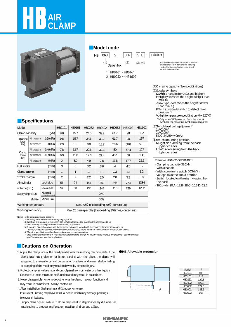
1. Adjust the clamp face of the mold parallel with the molding machine plate. If the clamp face has projection or is not parallel with the plate, the clamp will subjected to uneven force, and deformation of a lever and a main shaft or falling or dropping of the mold may result followed by personal injury.
2. Protect clamp, air valve unit and control panel from oil, water or other liquids. Exposure to these can cause malfunction and may result in an accident. 3. Never disassemble nor remodel, otherwise the clamp may not function and may result in an accident. Always contact us.4. After installation, �ush piping and �ttings prior to use. Insu�cient �ushing may leave residual debris which may damage packings to cause air leakage.5. Supply clean dry air. Failure to do so may result in degradation by dirt and / or
rust leading to product malfunction. Install an air dryer and a �lter.
Model code
Model
Clamp capacity
Full stroke
Clamp stroke
Stroke margin
Air cylinder
volume(cm3)
Supply air pressure
(MPa)
Working temperature
Working frequency
(kN)
(mm)
(mm)
(mm)
Lock side
Release side
Minimum
0.39MPa
0MPa
0.49MPa
0.39MPa
0MPa
HB0101
9.8
9.8
2.9
7.8
6.9
2
3
1
2
56
52
HB0161
15.7
15.7
5.9
13.7
11.8
3.9
3
1
2
94
88
HB0252
24.5
24.5
8.8
20.6
17.6
4.9
3.2
1
2.2
144
135
HB0402
39.2
39.2
13.7
32.3
27.4
7.8
3.6
1.1
2.5
259
244
HB0632
61.7
61.7
20.6
50
43.1
11.8
4
1.2
2.8
444
416
HB1002
98
98
30.8
77.4
66
17.7
4.5
1.2
3.3
773
729
HB1602
157
157
50.3
127
108
28.9
5
1.2
3.8
1334
1262
Retainingforce(kN)
Clampforce(kN)
Normal(recommended)
Air pressure
Air pressure
Air pressure
Air pressure
Air pressure
Specifications
0.49
0.39
Max. 70 (If exceeding 70 , contact us.)
Max. 20 times per day (If exceeding 20 times, contact us.)
Notes) 1. Do not exceed clamp capacity.2. Retaining force and clamp force may vary by 10%.3. Supply air at a pressure of more than 0.39 MPa to release port to maintain the release condition.4. Keep accuracy of clamp thickness (dimension h) at 0.3mm.5. Dimension E is kept constant and dimension M is changed to deal with the speci�ed thickness (dimension h).
If dimension E cannot be increased because of interference due to minimum mold thickness limitation, contact us.6. When the speci�cations other than the above are needed, contact us.7. Speci�cations and contents of this document are subject to change without notice to improve the products. Request technical speci�cations prior to actual application.
Cautions on Operation
Switch load voltage (current)1:AC100V2:AC200V5:DC 24V(5~40mA)Switch mounting positionR:Right side viewing from the back (cylinder side)L :Left side viewing from the back (cylinder side)
Clamping capacity 39.2kNWith a handleWith a proximity switch DC24V in voltage to detect mold positionSwitch located on the right viewing from the backT001⇒h=30,A=17,B=28,C=10.5,D=23.6
Only when "P" is selected from the special symbols, the following symbols are required:
1
Clamping capacity (See speci�cations)Special symbolsD:With a handle (for 0402 and higher)H:High type (When the height is larger than max. h)J:Low type lever (When the height is lower than min. h.)P:With a proximity switch to detect mold positionV:High temperature speci�cation (0~120℃)
1
HB Allowable protrusion
ModelHB0101HB0161HB0252HB0402HB0632HB1002HB1602
108113
122.5127.5124.5133.5167
T***This number represents the main specificationof the clamp’s T-slot stem and the clampingheight.After the specification is confirmed,we will createa number.
③
④
Example HB0402-DP-5R-T001
Outline dimensions
a
b
dc
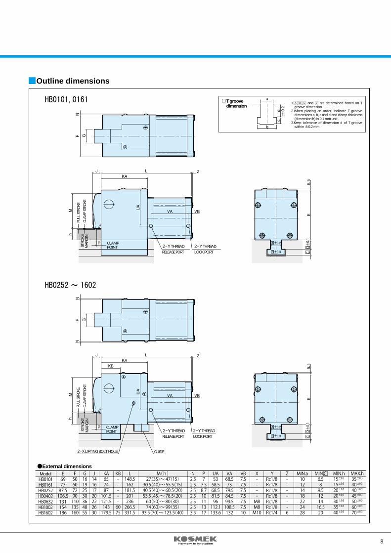
T groovedimension
0.2
1.A,B,C and D are determined based on T groove dimension.
2.When placing an order, indicate T groove dimensions a, b, c and d and clamp thickness (dimension h) in 0.1 mm unit.
3.Keep tolerance of dimension d of T groove within ±0.2 mm.
External dimensionsMAX.h35404045506070
MIN.h15152020303540
MIN.C6.589.5121416.520
MIN.a10121418222428
P77.58.710111317
N2.52.52.52.52.52.53.5
M(h)27(35)~47(15)30.5(40)~55.5(15)40.5(40)~60.5(20)53.5(45)~78.5(20)60(50)~80(30)74(60)~99(35)93.5(70)~123.5(40)
L148.5162181.5201236266.5331.5
KA657487101.5121.5143179.5
UA5358.568.581.596112.1133.6
VA68.57379.584.599.5108.5132
VB7.57.57.57.57.57.510
X----M8M8M10
Z------6
YRc1/8Rc1/8Rc1/8Rc1/8Rc1/8Rc1/8Rc1/4
KB-----6075
J14161720222630
G16192530364855
F50607290110135160
E697787.5106.5131154186
ModelHB0101HB0161HB0252HB0402HB0632HB1002HB1602
±0.3
±0.3
±0.3
±0.3
±0.3
±0.3
±0.3
±0.3
±0.3
±0.3
±0.3
±0.3
±0.3
±0.3
HB0101,0161
HB0252~ 1602
GUIDE
LOCK PORT2-Y THREAD
RELEASE PORT2-Y THREAD
CLAMPPOINTST
ROKE
MA
RGIN
FULL
STR
OKE
CLAM
P ST
ROKE
2-X LIFTING BOLT HOLE
LOCK PORT2-Y THREAD
RELEASE PORT2-Y THREAD
CLAMPPOINTST
ROKE
MA
RGIN
FULL
STR
OKE
CLAM
P ST
ROKE
1 : HB0101・HB01612 : HB0252 ~ HB1602
7 8
AIRCLAMP
HB 063 2 5 L
Design No.
DHP
1. Adjust the clamp face of the mold parallel with the molding machine plate. If the clamp face has projection or is not parallel with the plate, the clamp will subjected to uneven force, and deformation of a lever and a main shaft or falling or dropping of the mold may result followed by personal injury.
2. Protect clamp, air valve unit and control panel from oil, water or other liquids. Exposure to these can cause malfunction and may result in an accident. 3. Never disassemble nor remodel, otherwise the clamp may not function and may result in an accident. Always contact us.4. After installation, �ush piping and �ttings prior to use. Insu�cient �ushing may leave residual debris which may damage packings to cause air leakage.5. Supply clean dry air. Failure to do so may result in degradation by dirt and / or
rust leading to product malfunction. Install an air dryer and a �lter.
Model code
Model
Clamp capacity
Full stroke
Clamp stroke
Stroke margin
Air cylinder
volume(cm3)
Supply air pressure
(MPa)
Working temperature
Working frequency
(kN)
(mm)
(mm)
(mm)
Lock side
Release side
Minimum
0.39MPa
0MPa
0.49MPa
0.39MPa
0MPa
HB0101
9.8
9.8
2.9
7.8
6.9
2
3
1
2
56
52
HB0161
15.7
15.7
5.9
13.7
11.8
3.9
3
1
2
94
88
HB0252
24.5
24.5
8.8
20.6
17.6
4.9
3.2
1
2.2
144
135
HB0402
39.2
39.2
13.7
32.3
27.4
7.8
3.6
1.1
2.5
259
244
HB0632
61.7
61.7
20.6
50
43.1
11.8
4
1.2
2.8
444
416
HB1002
98
98
30.8
77.4
66
17.7
4.5
1.2
3.3
773
729
HB1602
157
157
50.3
127
108
28.9
5
1.2
3.8
1334
1262
Retainingforce(kN)
Clampforce(kN)
Normal(recommended)
Air pressure
Air pressure
Air pressure
Air pressure
Air pressure
Specifications
0.49
0.39
Max. 70 (If exceeding 70 , contact us.)
Max. 20 times per day (If exceeding 20 times, contact us.)
Notes) 1. Do not exceed clamp capacity.2. Retaining force and clamp force may vary by 10%.3. Supply air at a pressure of more than 0.39 MPa to release port to maintain the release condition.4. Keep accuracy of clamp thickness (dimension h) at 0.3mm.5. Dimension E is kept constant and dimension M is changed to deal with the speci�ed thickness (dimension h).
If dimension E cannot be increased because of interference due to minimum mold thickness limitation, contact us.6. When the speci�cations other than the above are needed, contact us.7. Speci�cations and contents of this document are subject to change without notice to improve the products. Request technical speci�cations prior to actual application.
Cautions on Operation
Switch load voltage (current)1:AC100V2:AC200V5:DC 24V(5~40mA)Switch mounting positionR:Right side viewing from the back (cylinder side)L :Left side viewing from the back (cylinder side)
Clamping capacity 39.2kNWith a handleWith a proximity switch DC24V in voltage to detect mold positionSwitch located on the right viewing from the backT001⇒h=30,A=17,B=28,C=10.5,D=23.6
Only when "P" is selected from the special symbols, the following symbols are required:
1
Clamping capacity (See speci�cations)Special symbolsD:With a handle (for 0402 and higher)H:High type (When the height is larger than max. h)J:Low type lever (When the height is lower than min. h.)P:With a proximity switch to detect mold positionV:High temperature speci�cation (0~120℃)
1
HB Allowable protrusion
ModelHB0101HB0161HB0252HB0402HB0632HB1002HB1602
108113
122.5127.5124.5133.5167
T***This number represents the main specificationof the clamp’s T-slot stem and the clampingheight.After the specification is confirmed,we will createa number.
③
④
Example HB0402-DP-5R-T001
Outline dimensions
a
b
dc
T groovedimension
0.2
1.A,B,C and D are determined based on T groove dimension.
2.When placing an order, indicate T groove dimensions a, b, c and d and clamp thickness (dimension h) in 0.1 mm unit.
3.Keep tolerance of dimension d of T groove within ±0.2 mm.
External dimensionsMAX.h35404045506070
MIN.h15152020303540
MIN.C6.589.5121416.520
MIN.a10121418222428
P77.58.710111317
N2.52.52.52.52.52.53.5
M(h)27(35)~47(15)30.5(40)~55.5(15)40.5(40)~60.5(20)53.5(45)~78.5(20)60(50)~80(30)74(60)~99(35)93.5(70)~123.5(40)
L148.5162181.5201236266.5331.5
KA657487101.5121.5143179.5
UA5358.568.581.596112.1133.6
VA68.57379.584.599.5108.5132
VB7.57.57.57.57.57.510
X----M8M8M10
Z------6
YRc1/8Rc1/8Rc1/8Rc1/8Rc1/8Rc1/8Rc1/4
KB-----6075
J14161720222630
G16192530364855
F50607290110135160
E697787.5106.5131154186
ModelHB0101HB0161HB0252HB0402HB0632HB1002HB1602
±0.3
±0.3
±0.3
±0.3
±0.3
±0.3
±0.3
±0.3
±0.3
±0.3
±0.3
±0.3
±0.3
±0.3
HB0101,0161
HB0252~ 1602
GUIDE
LOCK PORT2-Y THREAD
RELEASE PORT2-Y THREAD
CLAMPPOINTST
ROKE
MA
RGIN
FULL
STR
OKE
CLAM
P ST
ROKE
2-X LIFTING BOLT HOLE
LOCK PORT2-Y THREAD
RELEASE PORT2-Y THREAD
CLAMPPOINTST
ROKE
MA
RGIN
FULL
STR
OKE
CLAM
P ST
ROKE
1 : HB0101・HB01612 : HB0252 ~ HB1602
9 10
ModelHE0101HE0161HE0252HE0402HE0632HE1002HE1602
108113
122.5127.5124.5133.5167
T***This number represents the main specificationof the clamp’s T-slot stem and the clampingheight.After the specification is confirmed,we will createa number.
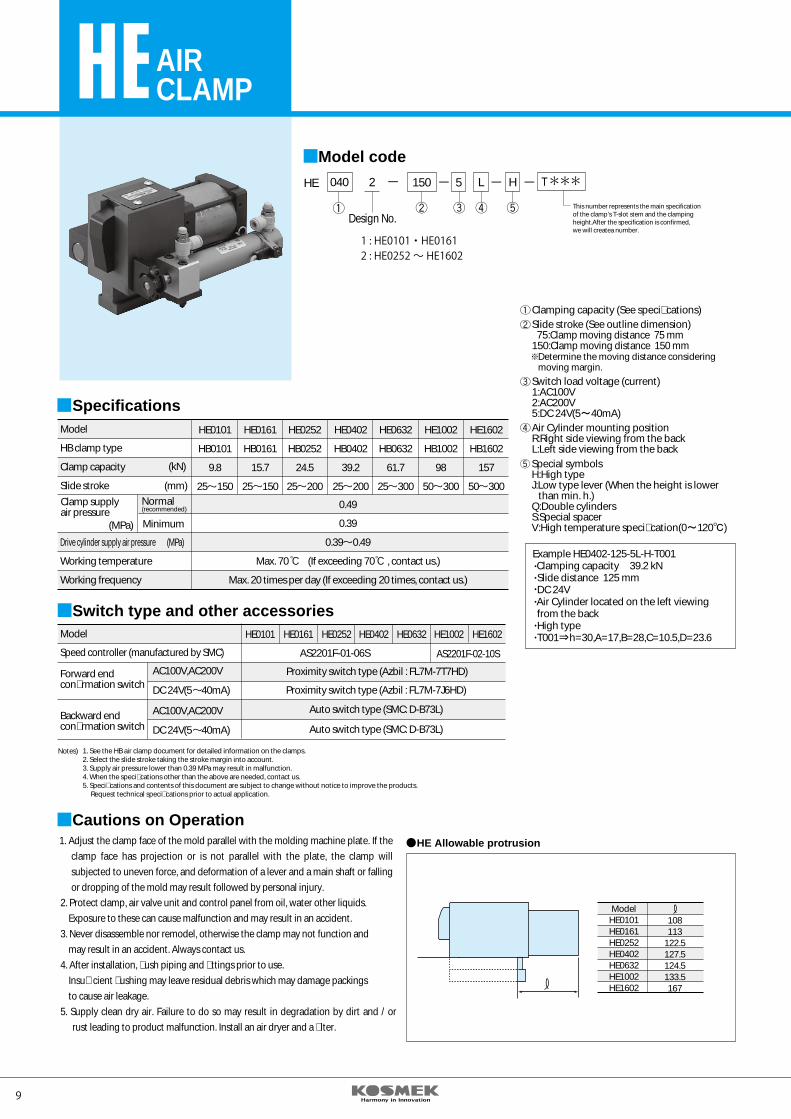
HE 040 2
Design No.
150 5 L H
Model code
AIRCLAMP
Example HE0402-125-5L-H-T001 Clamping capacity 39.2 kN Slide distance 125 mm DC 24V Air Cylinder located on the left viewing from the back High type T001⇒h=30,A=17,B=28,C=10.5,D=23.6
Special symbolsH:High typeJ:Low type lever (When the height is lower than min. h.)Q:Double cylindersS:Special spacerV:High temperature speci�cation(0~120℃)
Clamping capacity (See speci�cations)Slide stroke (See outline dimension) 75:Clamp moving distance 75 mm 150:Clamp moving distance 150 mm Determine the moving distance considering moving margin.Switch load voltage (current)1:AC100V2:AC200V5:DC 24V(5~40mA)Air Cylinder mounting positionR:Right side viewing from the back L:Left side viewing from the back
1. See the HB air clamp document for detailed information on the clamps.2. Select the slide stroke taking the stroke margin into account.3. Supply air pressure lower than 0.39 MPa may result in malfunction.4. When the speci�cations other than the above are needed, contact us.5. Speci�cations and contents of this document are subject to change without notice to improve the products.
Request technical speci�cations prior to actual application.
Notes)
Model
HB clamp type
Clamp capacity
Slide stroke
Drive cylinder supply air pressure
Working temperature
Working frequency
(kN)
(mm)
(MPa)
(MPa)
Clamp supplyair pressure
Normal(recommended)
Minimum
SpecificationsHE0101
HB0101
9.8
25 150
HE0161
HB0161
15.7
25 150
HE0252
HB0252
24.5
25 200
HE0402
HB0402
39.2
25 200
HE0632
HB0632
61.7
25 300
HE1002
HB1002
98
50 300
HE1602
HB1602
157
50 300
0.49
0.39
0.39 0.49
Max. 70 (If exceeding 70 , contact us.)
Max. 20 times per day (If exceeding 20 times, contact us.)
Proximity switch type (Azbil : FL7M-7J6HD)
Auto switch type (SMC: D-B73L)
Auto switch type (SMC: D-B73L)
HE0101 HE0161 HE0252 HE0402 HE0632 HE1002 HE1602
AS2201F-01-06S AS2201F-02-10SSpeed controller (manufactured by SMC)
Model
Forward endcon�rmation switch
Backward endcon�rmation switch
Proximity switch type (Azbil : FL7M-7T7HD)
Switch type and other accessories
AC100V,AC200V
DC 24V(5 40mA)
AC100V,AC200V
DC 24V(5 40mA)
1. Adjust the clamp face of the mold parallel with the molding machine plate. If the clamp face has projection or is not parallel with the plate, the clamp will subjected to uneven force, and deformation of a lever and a main shaft or falling or dropping of the mold may result followed by personal injury.
2. Protect clamp, air valve unit and control panel from oil, water other liquids. Exposure to these can cause malfunction and may result in an accident. 3. Never disassemble nor remodel, otherwise the clamp may not function and may result in an accident. Always contact us.4. After installation, �ush piping and �ttings prior to use. Insu�cient �ushing may leave residual debris which may damage packings to cause air leakage.5. Supply clean dry air. Failure to do so may result in degradation by dirt and / or
rust leading to product malfunction. Install an air dryer and a �lter.
Cautions on OperationHE Allowable protrusion
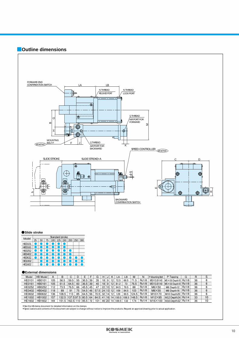
FORWARD ENDCONFIRMATION SWITCH
SLIDE STROKE SLIDE STROKE+A
RELEASE PORTN THREADN THREADLOCK PORT
Q THREADAIR PORT FORFORWARD
AIR PORT FORBACKWARD
Q THREAD
BACKWARDCONFIRMATION SWITCH
Model
HE0101HE0161HE0252HE0402HE0632HE1002HE1602
Standard stroke50 75 100 125 150 200 250 30025
Outline dimensions
Slide stroke
External dimensions
See the HB clamp document for detailed information on the clamps.Speci�cations and contents of this document are subject to change without notice to improve the products. Request an approval drawing prior to actual application.
R
E
C D
h
LA LB
GH
B
F J
M
K
MOUNTINGBOLT Pattached
SPEED CONTROLLERattached
72
LA72.581.294.5109129
150.5189.5
LB68.573
79.584.599.5108.5132169
Model HB Model P Mounting Bolt P Tapping
M5×0.8 Depth10M5×0.8 Depth10M6 Depth12M8 Depth16M10 Depth20M12 Depth24M16 Depth32
S666661010
φS
1 : HE0101・HE01612 : HE0252 ~ HE1602
9 10
ModelHE0101HE0161HE0252HE0402HE0632HE1002HE1602
108113
122.5127.5124.5133.5167
T***This number represents the main specificationof the clamp’s T-slot stem and the clampingheight.After the specification is confirmed,we will createa number.
HE 040 2
Design No.
150 5 L H
Model code
AIRCLAMP
Example HE0402-125-5L-H-T001 Clamping capacity 39.2 kN Slide distance 125 mm DC 24V Air Cylinder located on the left viewing from the back High type T001⇒h=30,A=17,B=28,C=10.5,D=23.6
Special symbolsH:High typeJ:Low type lever (When the height is lower than min. h.)Q:Double cylindersS:Special spacerV:High temperature speci�cation(0~120℃)
Clamping capacity (See speci�cations)Slide stroke (See outline dimension) 75:Clamp moving distance 75 mm 150:Clamp moving distance 150 mm Determine the moving distance considering moving margin.Switch load voltage (current)1:AC100V2:AC200V5:DC 24V(5~40mA)Air Cylinder mounting positionR:Right side viewing from the back L:Left side viewing from the back
1. See the HB air clamp document for detailed information on the clamps.2. Select the slide stroke taking the stroke margin into account.3. Supply air pressure lower than 0.39 MPa may result in malfunction.4. When the speci�cations other than the above are needed, contact us.5. Speci�cations and contents of this document are subject to change without notice to improve the products.
Request technical speci�cations prior to actual application.
Notes)
Model
HB clamp type
Clamp capacity
Slide stroke
Drive cylinder supply air pressure
Working temperature
Working frequency
(kN)
(mm)
(MPa)
(MPa)
Clamp supplyair pressure
Normal(recommended)
Minimum
SpecificationsHE0101
HB0101
9.8
25 150
HE0161
HB0161
15.7
25 150
HE0252
HB0252
24.5
25 200
HE0402
HB0402
39.2
25 200
HE0632
HB0632
61.7
25 300
HE1002
HB1002
98
50 300
HE1602
HB1602
157
50 300
0.49
0.39
0.39 0.49
Max. 70 (If exceeding 70 , contact us.)
Max. 20 times per day (If exceeding 20 times, contact us.)
Proximity switch type (Azbil : FL7M-7J6HD)
Auto switch type (SMC: D-B73L)
Auto switch type (SMC: D-B73L)
HE0101 HE0161 HE0252 HE0402 HE0632 HE1002 HE1602
AS2201F-01-06S AS2201F-02-10SSpeed controller (manufactured by SMC)
Model
Forward endcon�rmation switch
Backward endcon�rmation switch
Proximity switch type (Azbil : FL7M-7T7HD)
Switch type and other accessories
AC100V,AC200V
DC 24V(5 40mA)
AC100V,AC200V
DC 24V(5 40mA)
1. Adjust the clamp face of the mold parallel with the molding machine plate. If the clamp face has projection or is not parallel with the plate, the clamp will subjected to uneven force, and deformation of a lever and a main shaft or falling or dropping of the mold may result followed by personal injury.
2. Protect clamp, air valve unit and control panel from oil, water other liquids. Exposure to these can cause malfunction and may result in an accident. 3. Never disassemble nor remodel, otherwise the clamp may not function and may result in an accident. Always contact us.4. After installation, �ush piping and �ttings prior to use. Insu�cient �ushing may leave residual debris which may damage packings to cause air leakage.5. Supply clean dry air. Failure to do so may result in degradation by dirt and / or
rust leading to product malfunction. Install an air dryer and a �lter.
Cautions on OperationHE Allowable protrusion
FORWARD ENDCONFIRMATION SWITCH
SLIDE STROKE SLIDE STROKE+A
RELEASE PORTN THREADN THREADLOCK PORT
Q THREADAIR PORT FORFORWARD
AIR PORT FORBACKWARD
Q THREAD
BACKWARDCONFIRMATION SWITCH
Model
HE0101HE0161HE0252HE0402HE0632HE1002HE1602
Standard stroke50 75 100 125 150 200 250 30025
Outline dimensions
Slide stroke
External dimensions
See the HB clamp document for detailed information on the clamps.Speci�cations and contents of this document are subject to change without notice to improve the products. Request an approval drawing prior to actual application.
R
EC D
h
LA LB
GH
B
F JM
K
MOUNTINGBOLT Pattached
SPEED CONTROLLERattached
72
LA72.581.294.5109129
150.5189.5
LB68.573
79.584.599.5108.5132169
Model HB Model P Mounting Bolt P Tapping
M5×0.8 Depth10M5×0.8 Depth10M6 Depth12M8 Depth16M10 Depth20M12 Depth24M16 Depth32
S666661010
φS
1 : HE0101・HE01612 : HE0252 ~ HE1602
11 12
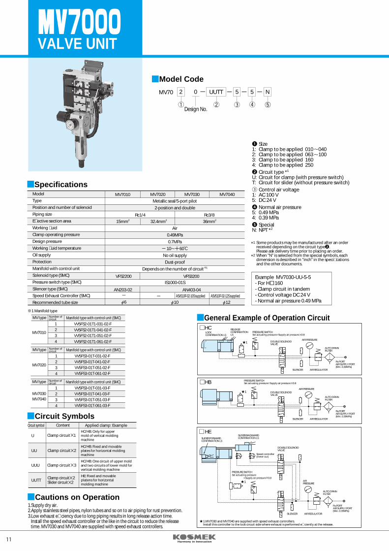
VALVE UNIT
MV70 2 0
Design No.
UUTT 5 N5
Model Code
❶ Size1: Clamp to be applied 010 0402: Clamp to be applied 063 1003: Clamp to be applied 1604: Clamp to be applied 250❷ Circuit type *1
U: Circuit for clamp (with pressure switch)T: Circuit for slider (without pressure switch)③ Control air voltage1: AC 100 V5: DC 24 V❹ Normal air pressure5: 0.49 MPa4: 0.39 MPa❺ SpecialN: NPT *2
1
2
Some products may be manufactured after an order received depending on the circuit type❷. Please ask delivery time prior to placing an order.When "N" is selected from the special symbols, each dimension is described in "inch" in the speci�cations and the other documents.
Example MV7030-UU-5-5- For H□160- Clamp circuit in tandem- Control voltage DC 24 V- Normal air pressure 0.49 MPa
MV7010
Rc1/4 Rc3/815mm2 36mm232.4mm2
MV7020 MV7030 MV7040
VFS2200 VFS3200
AN203-02 AN403-04ASV510F-02-10S supplied ASV510F-02-12S supplied
Specifications
Metallic seal/5-port pilot2-position and double
Air0.49MPa0.7MPa
10 60 No oil supplyDust-proof
Depends on the number of circuit 1
IS1000-01S
106 12
Model
Type
Position and number of solenoid
Piping size
E�ective section area
Working �uid
Clamp operating pressure
Design pressure
Working �uid temperature
Oil supply
Protection
Manifold with control unit
Solenoid type (SMC)
Pressure switch type (SMC)
Silencer type (SMC)
Speed Exhaust Controller (SMC)
Recommended tube size
MV7010
1234
VV5FS2-01T1-031-02-FVV5FS2-01T1-041-02-FVV5FS2-01T1-051-02-FVV5FS2-01T1-061-02-F
MV type Number ofcircuit Manifold type with control unit (SMC)
MV7020
1234
VV5FS3-01T-031-02-FVV5FS3-01T-041-02-FVV5FS3-01T-051-02-FVV5FS3-01T-061-02-F
MV type Number ofcircuit Manifold type with control unit (SMC)
MV7030MV7040
1234
VV5FS3-01T-031-03-FVV5FS3-01T-041-03-FVV5FS3-01T-051-03-FVV5FS3-01T-061-03-F
MV type Number ofcircuit Manifold type with control unit (SMC)
1 Manifold type
1.Supply dry air. 2.Apply stainless steel pipes, nylon tubes and so on to air piping for rust prevention.3.Low exhaust e�ciency due to long piping results in long release action time. Install the speed exhaust controller or the like in the circuit to reduce the release time. MV7030 and MV7040 are supplied with speed exhaust controllers.
Cautions on Operation
Circuit symbol Content Applied clamp: Example
U
UU
UUU
UUTT
HC/HB: Only for uppermold of vertical moldingmachine
HC/HB: Fixed and movableplates for horizontal moldingmachine
HC/HB: One circuit of upper moldand two circuits of lower mold forvertical molding machine
HE: Fixed and movableplatens for horizontalmolding machine
Circuit Symbols
Clamp circuit 1
Clamp circuit 2
Clamp circuit 3
Clamp circuit 2Slider circuit 2
LOCKCONFIRMATION LS
RELEASECONFIRMATIONLS
PRESSURE SWITCHSet actuating pressure=Supply air pressure 0.8
DOUBLE SOLENOIDVALVE
AIR PRESSURE
SILENCER AIR REGULATOR
AUTO DRAINFILTER
Pa PORTAIR SUPPLY PORT(Min. 0.39MPa)
General Example of Operation CircuitHC
1
HB PRESSURE SWITCHSet actuating pressure=Supply air pressure 0.8
DOUBLE SOLENOIDVALVE
AIR PRESSURE
SILENCER AIR REGULATOR
AUTO DRAINFILTER
Pa PORTAIR SUPPLY PORT(Min. 0.39MPa)
1
SLIDER FORWARDCONFIRMATION LS
SLIDER BACKWARDCONFIRMATION LS
Speed controller(meter out)
DOUBLE SOLENOIDVALVE
PRESSURE SWITCHSet actuating pressure =Supply air pressure 0.8
AIRPRESSURE
AUTO DRAINFILTER
Pa PORTAIR SUPPLY PORT(Min. 0.39MPa)
SILENCER AIR REGULATOR
HE
1
1.MV7030 and MV7040 are supplied with speed exhaust controllers.Install this controller to the lock circuit side where exhaust is performed e�ciently at the release.
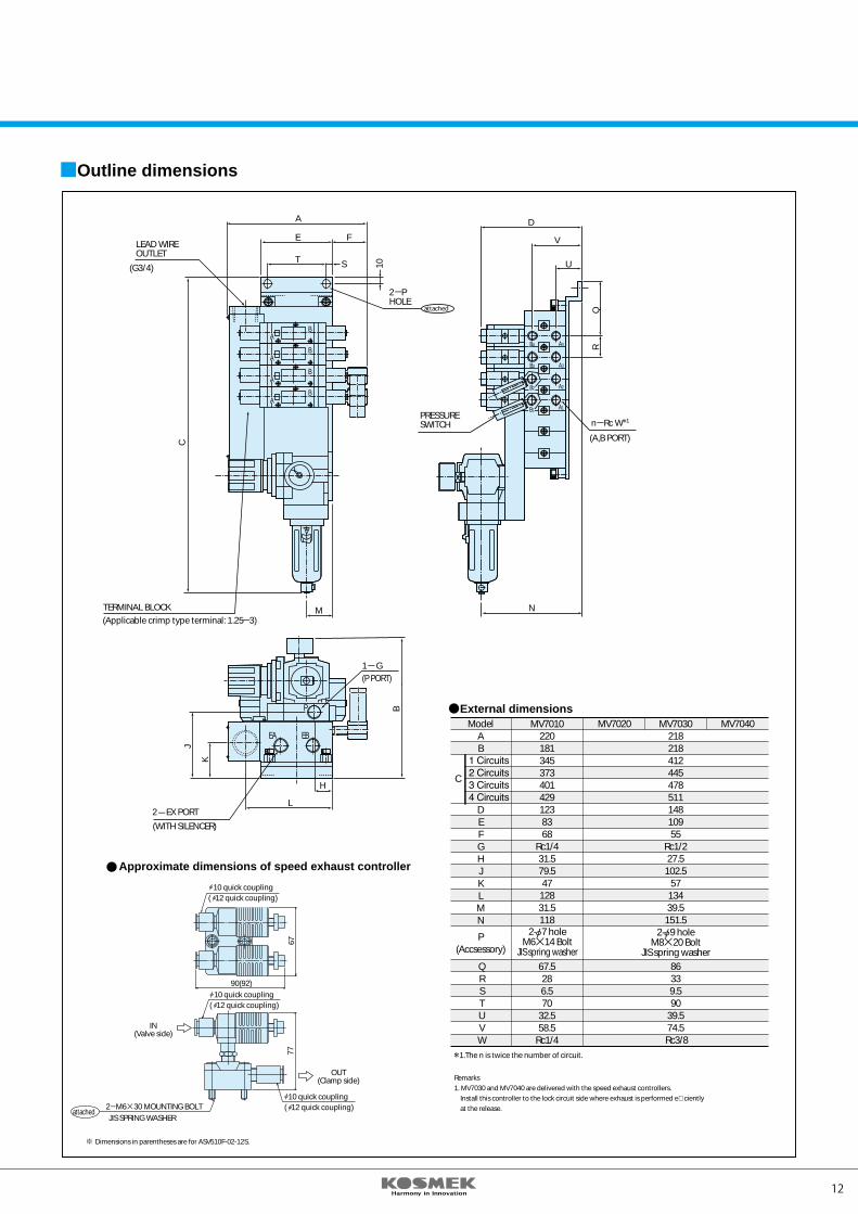
Outline dimensions
Approximate dimensions of speed exhaust controller
Remarks1. MV7030 and MV7040 are delivered with the speed exhaust controllers. Install this controller to the lock circuit side where exhaust is performed e�ciently at the release.
Dimensions in parentheses are for ASV510F-02-12S.77
67
90(92)
External dimensionsModel
AB
DEFGHJKLMN
P(Accsessory)
MV70102201813453734014291238368
Rc1/431.579.547
12831.5118
MV7020 MV7040
C
QRSTUVW
67.5286.570
32.558.5
Rc1/4
MV703021821841244547851114810955
Rc1/227.5
102.557
13439.5
151.5
86339.590
39.574.5
Rc3/8
2- 9 holeM8 20 Bolt
JIS spring washer
2- 7 holeM6 14 Bolt
JIS spring washer
1.The n is twice the number of circuit.
LEAD WIREOUTLET
(P PORT)
2 EX PORT
(WITH SILENCER)
attached
(Applicable crimp type terminal: 1.25 3)TERMINAL BLOCK
2 PHOLE
PRESSURESWITCH
(A,B PORT)
D
V
U
N
A4B4
A3B3
A2B2
A1B1
QR
n Rc W 1
L
H
B
EBEA
P
K
J
1-G
A
E
(G3/4)T
F
S
M
10
C
A
A
A
A
B
B
B
B
IN(Valve side)
OUT(Clamp side)
attached
10 quick coupling( 12 quick coupling)
10 quick coupling( 12 quick coupling)
10 quick coupling( 12 quick coupling)2 M6 30 MOUNTING BOLT
JIS SPRING WASHER
11 12
VALVE UNIT
MV70 2 0
Design No.
UUTT 5 N5
Model Code
❶ Size1: Clamp to be applied 010 0402: Clamp to be applied 063 1003: Clamp to be applied 1604: Clamp to be applied 250❷ Circuit type *1
U: Circuit for clamp (with pressure switch)T: Circuit for slider (without pressure switch)③ Control air voltage1: AC 100 V5: DC 24 V❹ Normal air pressure5: 0.49 MPa4: 0.39 MPa❺ SpecialN: NPT *2
1
2
Some products may be manufactured after an order received depending on the circuit type❷. Please ask delivery time prior to placing an order.When "N" is selected from the special symbols, each dimension is described in "inch" in the speci�cations and the other documents.
Example MV7030-UU-5-5- For H□160- Clamp circuit in tandem- Control voltage DC 24 V- Normal air pressure 0.49 MPa
MV7010
Rc1/4 Rc3/815mm2 36mm232.4mm2
MV7020 MV7030 MV7040
VFS2200 VFS3200
AN203-02 AN403-04ASV510F-02-10S supplied ASV510F-02-12S supplied
Specifications
Metallic seal/5-port pilot2-position and double
Air0.49MPa0.7MPa
10 60 No oil supplyDust-proof
Depends on the number of circuit 1
IS1000-01S
106 12
Model
Type
Position and number of solenoid
Piping size
E�ective section area
Working �uid
Clamp operating pressure
Design pressure
Working �uid temperature
Oil supply
Protection
Manifold with control unit
Solenoid type (SMC)
Pressure switch type (SMC)
Silencer type (SMC)
Speed Exhaust Controller (SMC)
Recommended tube size
MV7010
1234
VV5FS2-01T1-031-02-FVV5FS2-01T1-041-02-FVV5FS2-01T1-051-02-FVV5FS2-01T1-061-02-F
MV type Number ofcircuit Manifold type with control unit (SMC)
MV7020
1234
VV5FS3-01T-031-02-FVV5FS3-01T-041-02-FVV5FS3-01T-051-02-FVV5FS3-01T-061-02-F
MV type Number ofcircuit Manifold type with control unit (SMC)
MV7030MV7040
1234
VV5FS3-01T-031-03-FVV5FS3-01T-041-03-FVV5FS3-01T-051-03-FVV5FS3-01T-061-03-F
MV type Number ofcircuit Manifold type with control unit (SMC)
1 Manifold type
1.Supply dry air. 2.Apply stainless steel pipes, nylon tubes and so on to air piping for rust prevention.3.Low exhaust e�ciency due to long piping results in long release action time. Install the speed exhaust controller or the like in the circuit to reduce the release time. MV7030 and MV7040 are supplied with speed exhaust controllers.
Cautions on Operation
Circuit symbol Content Applied clamp: Example
U
UU
UUU
UUTT
HC/HB: Only for uppermold of vertical moldingmachine
HC/HB: Fixed and movableplates for horizontal moldingmachine
HC/HB: One circuit of upper moldand two circuits of lower mold forvertical molding machine
HE: Fixed and movableplatens for horizontalmolding machine
Circuit Symbols
Clamp circuit 1
Clamp circuit 2
Clamp circuit 3
Clamp circuit 2Slider circuit 2
LOCKCONFIRMATION LS
RELEASECONFIRMATIONLS
PRESSURE SWITCHSet actuating pressure=Supply air pressure 0.8
DOUBLE SOLENOIDVALVE
AIR PRESSURE
SILENCER AIR REGULATOR
AUTO DRAINFILTER
Pa PORTAIR SUPPLY PORT(Min. 0.39MPa)
General Example of Operation CircuitHC
1
HB PRESSURE SWITCHSet actuating pressure=Supply air pressure 0.8
DOUBLE SOLENOIDVALVE
AIR PRESSURE
SILENCER AIR REGULATOR
AUTO DRAINFILTER
Pa PORTAIR SUPPLY PORT(Min. 0.39MPa)
1
SLIDER FORWARDCONFIRMATION LS
SLIDER BACKWARDCONFIRMATION LS
Speed controller(meter out)
DOUBLE SOLENOIDVALVE
PRESSURE SWITCHSet actuating pressure =Supply air pressure 0.8
AIRPRESSURE
AUTO DRAINFILTER
Pa PORTAIR SUPPLY PORT(Min. 0.39MPa)
SILENCER AIR REGULATOR
HE
1
1.MV7030 and MV7040 are supplied with speed exhaust controllers.Install this controller to the lock circuit side where exhaust is performed e�ciently at the release.
Outline dimensions
Approximate dimensions of speed exhaust controller
Remarks1. MV7030 and MV7040 are delivered with the speed exhaust controllers. Install this controller to the lock circuit side where exhaust is performed e�ciently at the release.
Dimensions in parentheses are for ASV510F-02-12S.
7767
90(92)
External dimensionsModel
AB
DEFGHJKLMN
P(Accsessory)
MV70102201813453734014291238368
Rc1/431.579.547
12831.5118
MV7020 MV7040
C
QRSTUVW
67.5286.570
32.558.5
Rc1/4
MV703021821841244547851114810955
Rc1/227.5
102.557
13439.5
151.5
86339.590
39.574.5
Rc3/8
2- 9 holeM8 20 Bolt
JIS spring washer
2- 7 holeM6 14 Bolt
JIS spring washer
1.The n is twice the number of circuit.
LEAD WIREOUTLET
(P PORT)
2 EX PORT
(WITH SILENCER)
attached
(Applicable crimp type terminal: 1.25 3)TERMINAL BLOCK
2 PHOLE
PRESSURESWITCH
(A,B PORT)
D
V
U
N
A4B4
A3B3
A2B2
A1B1
QR
n Rc W 1
L
H
B
EBEA
P
K
J
1-G
A
E
(G3/4)T
F
S
M
10
C
A
A
A
A
B
B
B
B
IN(Valve side)
OUT(Clamp side)
attached
10 quick coupling( 12 quick coupling)
10 quick coupling( 12 quick coupling)
10 quick coupling( 12 quick coupling)2 M6 30 MOUNTING BOLT
JIS SPRING WASHER
13 14
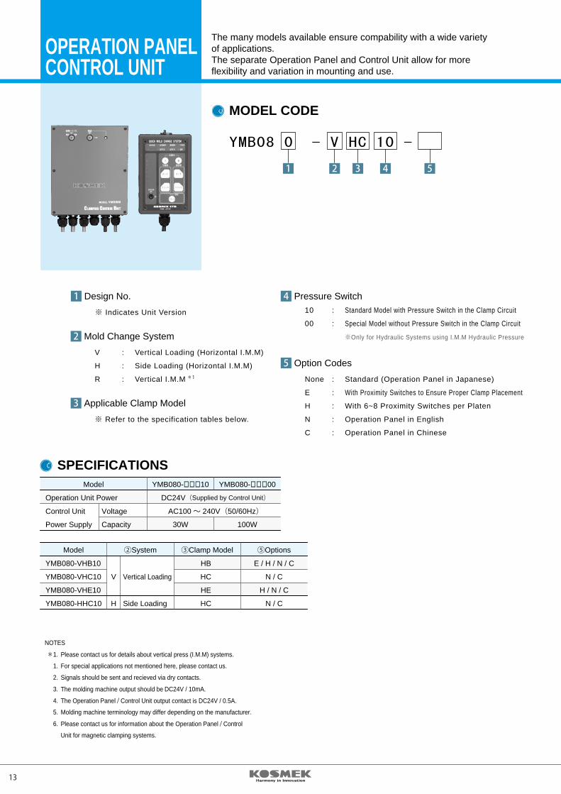
OPERATION PANELCONTROL UNIT
The many models available ensure compability with a wide varietyof applications.The separate Operation Panel and Control Unit allow for moreflexibility and variation in mounting and use.
1
MODEL CODE
YMB08 0 - V HC 10 -
3 4 52
10 : Standard Model with Pressure Switch in the Clamp Circuit
00 : Special Model without Pressure Switch in the Clamp Circuit
※Only for Hydraulic Systems using I.M.M Hydraulic Pressure
Pressure Switch4
Mold Change System2V : Vertical Loading (Horizontal I.M.M)
H : Side Loading (Horizontal I.M.M)
R : Vertical I.M.M *1
Applicable Clamp Model3※ Refer to the specification tables below.
Option Codes5None : Standard (Operation Panel in Japanese)
E : With Proximity Switches to Ensure Proper Clamp Placement
H : With 6~8 Proximity Switches per Platen
N : Operation Panel in English
C : Operation Panel in Chinese
SPECIFICATIONS Model YMB080-□□□10 YMB080-□□□00
Operation Unit Power DC24V(Supplied by Control Unit)
Control Unit Voltage AC100~ 240V(50/60Hz)
Power Supply Capacity 30W 100W
Model ②System ③Clamp Model ⑤Options
YMB080-VHB10 HB E / H / N / C
YMB080-VHC10 V Vertical Loading HC N / C
YMB080-VHE10 HE H / N / C
YMB080-HHC10 H Side Loading HC N / C
NOTES
*1. Please contact us for details about vertical press (I.M.M) systems.
1. For special applications not mentioned here, please contact us.
2. Signals should be sent and recieved via dry contacts.
3. The molding machine output should be DC24V / 10mA.
4. The Operation Panel / Control Unit output contact is DC24V / 0.5A.
5. Molding machine terminology may differ depending on the manufacturer.
6. Please contact us for information about the Operation Panel / Control
Unit for magnetic clamping systems.
Design No.1※ Indicates Unit Version
1550
15
15 20 40
Mounting Bracket
2-φ7 Hole
M6×12 Screw(Included)
I.M.MCOND.
COMN.ERROR POWER
ALARM
RESET
OFFMOLD CHANGE
ON
KOBE JAPAN
QUICK MOLD CHANGE SYSTEM
LOCK LOCK
RELEASE RELEASE
MOVABLE STATIONARY
MOLD OPEN OK
MOLD OPEN OK
MOLD CLOSE COMPLETED
固定金型
150
3580
35
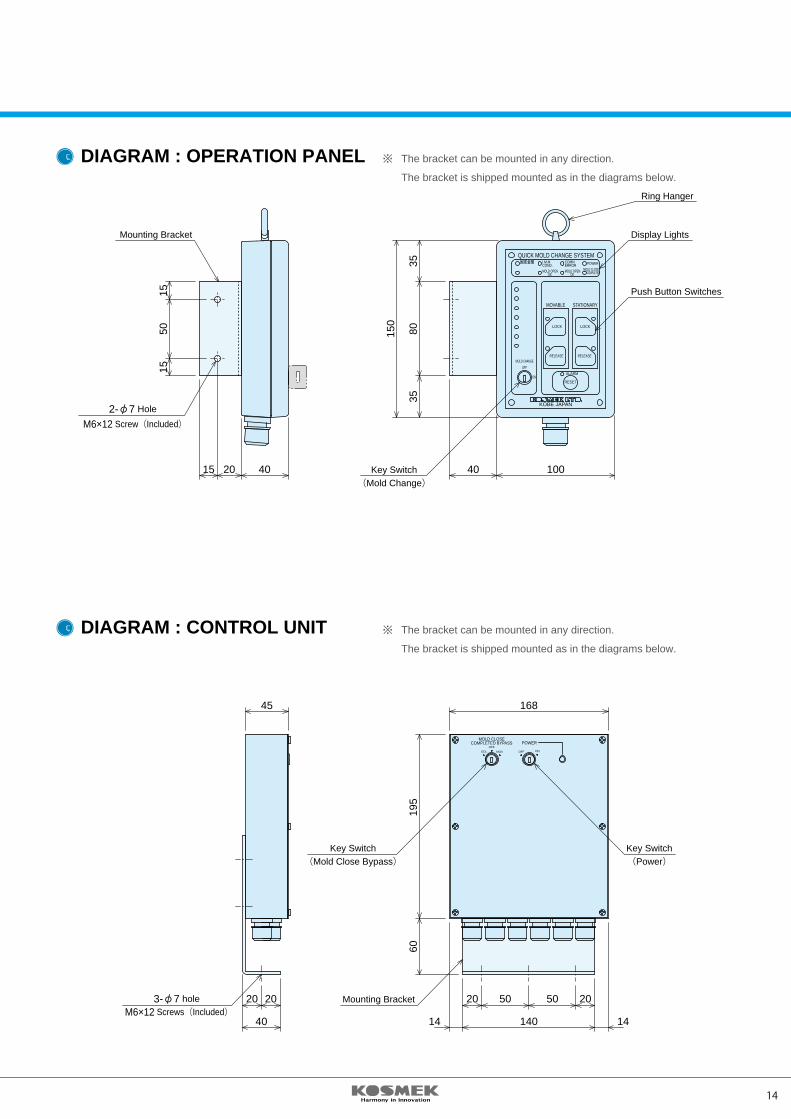
10040Key Switch(Mold Change)
Display Lights
Push Button Switches
Ring Hanger
3-φ7 holeM6×12 Screws(Included)
45
40
2020
POWEROFF
MOLD CLOSECOMPLETED BYPASS
ONOFFMOVSTA
6019
5
168
14140
205050
14
20
Key Switch(Power)
Key Switch(Mold Close Bypass)
Mounting Bracket
DIAGRAM : OPERATION PANEL ※ The bracket can be mounted in any direction.
The bracket is shipped mounted as in the diagrams below.
DIAGRAM : CONTROL UNIT ※ The bracket can be mounted in any direction.
The bracket is shipped mounted as in the diagrams below.
13 14
OPERATION PANELCONTROL UNIT
The many models available ensure compability with a wide varietyof applications.The separate Operation Panel and Control Unit allow for moreflexibility and variation in mounting and use.
1
MODEL CODE
YMB08 0 - V HC 10 -
3 4 52
10 : Standard Model with Pressure Switch in the Clamp Circuit
00 : Special Model without Pressure Switch in the Clamp Circuit
※Only for Hydraulic Systems using I.M.M Hydraulic Pressure
Pressure Switch4
Mold Change System2V : Vertical Loading (Horizontal I.M.M)
H : Side Loading (Horizontal I.M.M)
R : Vertical I.M.M *1
Applicable Clamp Model3※ Refer to the specification tables below.
Option Codes5None : Standard (Operation Panel in Japanese)
E : With Proximity Switches to Ensure Proper Clamp Placement
H : With 6~8 Proximity Switches per Platen
N : Operation Panel in English
C : Operation Panel in Chinese
SPECIFICATIONS Model YMB080-□□□10 YMB080-□□□00
Operation Unit Power DC24V(Supplied by Control Unit)
Control Unit Voltage AC100~ 240V(50/60Hz)
Power Supply Capacity 30W 100W
Model ②System ③Clamp Model ⑤Options
YMB080-VHB10 HB E / H / N / C
YMB080-VHC10 V Vertical Loading HC N / C
YMB080-VHE10 HE H / N / C
YMB080-HHC10 H Side Loading HC N / C
NOTES
*1. Please contact us for details about vertical press (I.M.M) systems.
1. For special applications not mentioned here, please contact us.
2. Signals should be sent and recieved via dry contacts.
3. The molding machine output should be DC24V / 10mA.
4. The Operation Panel / Control Unit output contact is DC24V / 0.5A.
5. Molding machine terminology may differ depending on the manufacturer.
6. Please contact us for information about the Operation Panel / Control
Unit for magnetic clamping systems.
Design No.1※ Indicates Unit Version
1550
15
15 20 40
Mounting Bracket
2-φ7 Hole
M6×12 Screw(Included)
I.M.MCOND.
COMN.ERROR POWER
ALARM
RESET
OFFMOLD CHANGE
ON
KOBE JAPAN
QUICK MOLD CHANGE SYSTEM
LOCK LOCK
RELEASE RELEASE
MOVABLE STATIONARY
MOLD OPEN OK
MOLD OPEN OK
MOLD CLOSE COMPLETED
固定金型
150
3580
35
10040Key Switch(Mold Change)
Display Lights
Push Button Switches
Ring Hanger
3-φ7 holeM6×12 Screws(Included)
45
40
2020
POWEROFF
MOLD CLOSECOMPLETED BYPASS
ONOFFMOVSTA
6019
5
168
14140
205050
14
20
Key Switch(Power)
Key Switch(Mold Close Bypass)
Mounting Bracket
DIAGRAM : OPERATION PANEL ※ The bracket can be mounted in any direction.
The bracket is shipped mounted as in the diagrams below.
DIAGRAM : CONTROL UNIT ※ The bracket can be mounted in any direction.
The bracket is shipped mounted as in the diagrams below.
15 16
OPERATION PANELCONTROL UNIT
OFFMOLD CHANGE
ON
OFFMOLD CHANGE
ON
I.M.M. COND.
COMN.ERROR POWER
MOLD OPEN OK
MOLD CLOSE OK
MOLD CLOSECOMPLETED
I.M.M. COND.
COMN.ERROR POWER
MOLD OPEN OK
MOLD CLOSE OK
MOLD CLOSECOMPLETED
I.M.M. COND.
COMN.ERROR POWER
MOLD OPEN OK
MOLD CLOSE OK
MOLD CLOSECOMPLETED
I.M.M. COND.
COMN.ERROR POWER
MOLD OPEN OK
MOLD CLOSE OK
MOLD CLOSECOMPLETED
RELEASE RELEASEMOVABLE STATIONARY
LOCK LOCKMOVABLE STATIONARY
RELEASE RELEASEMOVABLE STATIONARY
PUSH PUSH
LOCK LOCKMOVABLE STATIONARY
PUSH PUSH
I.M.M. COND.
COMN.ERROR POWER
MOLD OPEN OK
MOLD CLOSE OK
MOLD CLOSECOMPLETED
I.M.M. COND.
COMN.ERROR POWER
MOLD OPEN OK
MOLD CLOSE OK
MOLD CLOSECOMPLETED
MOV. FWD.
STA. BACK.
MOV. BACK.
STA. FWD.
MOV. FWD.
STA. BACK.
MOV. BACK.
STA. FWD.
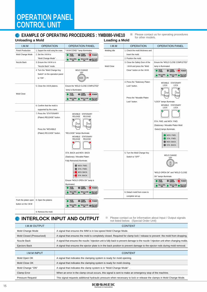
EXAMPLE OF OPERATING PROCEDURES : YMB080-VHE10
INTERLOCK INPUT AND OUTPUT
I.M.M OPERATION OPERATION PANEL Finish Production 1. Support the mold using the crane. “I.M.M COND.” lamp illuminates.
Mold Change Mode 2. Set the I.M.M to
“Mold Change Mode” .
Nozzle Back 3. Ensure the I.M.M is in
“Nozzle Back” mode.
4. Turn the “Mold Change Key
Switch” on the operation panel
to “ON” .
5. Close the I.M.M platens. Ensure the “MOLD CLOSE COMPLETED”
lamp is illuminated.
Mold Close
6. Confirm that the mold is
supported by the crane.
7. Press the “STATIONARY
(Platen) RELEASE” button.
Press the “MOVABLE
(Platen) RELEASE” button. “RELEASE” lamps illuminate.
STA. BACK and MOV. BACK
(Stationary / Movable Platen
Fully Retracted) illuminate.
Ensure “MOLD OPEN OK” lamp is
illuminated.
Push the platen open 8. Open the platens
button on the I.M.M
9. Remove the mold.
I.M.M OPERATION OPERATION PANEL Molding Idle 1. Check the mold thickness and
insert the mold.
2. Position the mold.
3. Close the Safety Door of the Ensure the “MOLD CLOSE COMPLETED”
Mold Close I.M.M and press the “Mold lamp is illuminated.
Close” button on the I.M.M.
4. Press the “Stationary Platen
Lock” button.
Press the “Movable Platen
Lock” button. “LOCK” lamps illuminate.
STA. FWD. and MOV. FWD.
(Stationary / Movable Platen Mold
Detect) lamps illuminate.
5. Turn the Mold Change Key
Switch to “OFF” .
“MOLD OPEN OK” and “MOLD CLOSE
OK” lamps illuminate.
6. Detach mold from crane to
complete set-up.
I.M.M OUTPUT CONTENT
Mold Change Mode A signal that ensures the IMM is in low-speed Mold Change Mode.
Mold Closed (Pressurized) A signal that ensures the mold is completely closed. Required for clamp lock / release to prevent the mold from dropping.
Nozzle Back A signal that ensures the nozzle / injection unit is fully back to prevent damage to the nozzle / injection unit when changing molds.
Ejectors Back A signal that ensures the ejector plate is in the back position to prevent damage to the ejector rods during mold removal.
I.M.M INPUT CONTENT
Mold Open OK A signal that indicates the clamping system is ready for mold opening.
Mold Close OK A signal that indicates the clamping system is ready for mold closing.
Mold Change “ON” A signal that indicates the clamp system is in “Mold Change Mode” .
Clamp Error When an error in the clamp circuit occurs, this signal is sent to make an emergency stop of the machine.
Pressure Request This signal requests additional hydraulic pressure when necessary to lock or release the clamps in Mold Change Mode.
Unloading a Mold Loading a Mold
※ Please contact us for operating procedures for other models.
※ Please contact us for information about Input / Output signals not listed below. (Special Order Unit)
I.M.MCOND.
COMN.ERROR
POWER
ALARMOFF
MOLD CHANGE
ON
KOBE JAPAN
QUICK MOLD CHANGE SYSTEM
LOCK LOCK
RELEASE RELEASE
MOVABLE STATIONARY
MOLD OPEN ON
MOLD CLOSE ON
MOLD CLOSE COMPLETED
I.M.MCOND.
I.M.MCOND.
COMN.ERROR
POWER
ALARMOFF
MOLD CHANGE
ON
KOBE JAPAN
QUICK MOLD CHANGE SYSTEM
LOCK LOCK
RELEASE RELEASE
MOVABLE STATIONARY
MOLD OPEN ON
MOLD CLOSE ON
MOLD CLOSE COMPLETED
I.M.MCOND.
I.M.MCOND.
COMN.ERROR
POWER
ALARMOFF
MOLD CHANGE
ON
KOBE JAPAN
QUICK MOLD CHANGE SYSTEM
LOCK LOCK
RELEASE RELEASE
MOVABLE STATIONARY
MOLD OPEN ON
MOLD CLOSE ON
MOLD CLOSE COMPLETED
I.M.MCOND.
POWEROFF
MOLD CLOSECOMPLETED BYPASS
ONOFFMOVSTA
POWEROFF
MOLD CLOSECOMLETED BYPASS
ONOFFMOV.STA.
POWEROFF
MOLD CLOSECOMPLETED BYPASS
ONOFFMOVSTA
POWEROFF
MOLD CLOSECOMPLETED BYPASS
ONOFFMOVSTA
40 (100)
(16) (40)35
(16)(40)35
(45)40
(45)40
38.5 (168) (168) 38.5
40(100)
(15
0 )15
I.M.MCOND.
COMN.ERROR
POWER
ALARMOFF
MOLD CHANGE
ON
KOBE JAPAN
QUICK MOLD CHANGE SYSTEM
LOCK LOCK
RELEASE RELEASE
MOVABLE STATIONARY
MOLD OPEN ON
MOLD CLOSE ON
MOLD CLOSE COMPLETED
I.M.MCOND.
(19
5 )40
(19
5 )60
65(1
50)
RESET
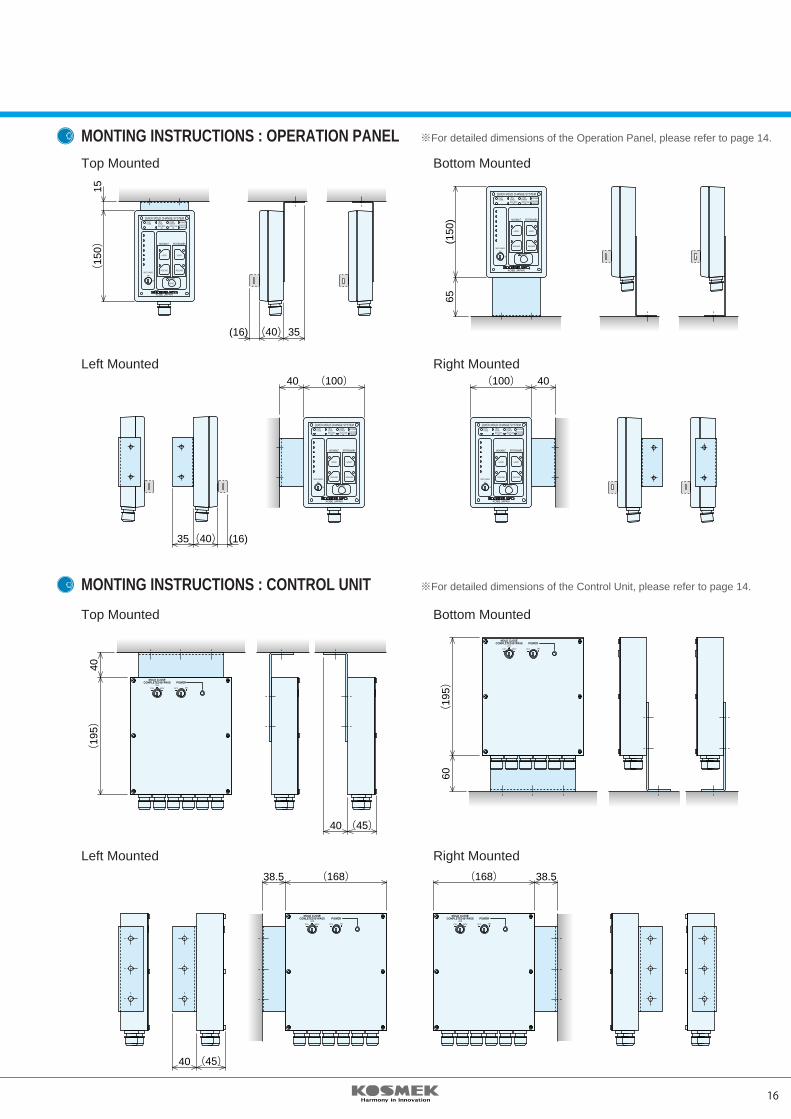
MONTING INSTRUCTIONS : OPERATION PANEL
MONTING INSTRUCTIONS : CONTROL UNIT
Top Mounted Bottom Mounted
Left Mounted Right Mounted
Top Mounted Bottom Mounted
Left Mounted Right Mounted
※For detailed dimensions of the Operation Panel, please refer to page 14.
※For detailed dimensions of the Control Unit, please refer to page 14.
15 16
OPERATION PANELCONTROL UNIT
OFFMOLD CHANGE
ON
OFFMOLD CHANGE
ON
I.M.M. COND.
COMN.ERROR POWER
MOLD OPEN OK
MOLD CLOSE OK
MOLD CLOSECOMPLETED
I.M.M. COND.
COMN.ERROR POWER
MOLD OPEN OK
MOLD CLOSE OK
MOLD CLOSECOMPLETED
I.M.M. COND.
COMN.ERROR POWER
MOLD OPEN OK
MOLD CLOSE OK
MOLD CLOSECOMPLETED
I.M.M. COND.
COMN.ERROR POWER
MOLD OPEN OK
MOLD CLOSE OK
MOLD CLOSECOMPLETED
RELEASE RELEASEMOVABLE STATIONARY
LOCK LOCKMOVABLE STATIONARY
RELEASE RELEASEMOVABLE STATIONARY
PUSH PUSH
LOCK LOCKMOVABLE STATIONARY
PUSH PUSH
I.M.M. COND.
COMN.ERROR POWER
MOLD OPEN OK
MOLD CLOSE OK
MOLD CLOSECOMPLETED
I.M.M. COND.
COMN.ERROR POWER
MOLD OPEN OK
MOLD CLOSE OK
MOLD CLOSECOMPLETED
MOV. FWD.
STA. BACK.
MOV. BACK.
STA. FWD.
MOV. FWD.
STA. BACK.
MOV. BACK.
STA. FWD.
EXAMPLE OF OPERATING PROCEDURES : YMB080-VHE10
INTERLOCK INPUT AND OUTPUT
I.M.M OPERATION OPERATION PANEL Finish Production 1. Support the mold using the crane. “I.M.M COND.” lamp illuminates.
Mold Change Mode 2. Set the I.M.M to
“Mold Change Mode” .
Nozzle Back 3. Ensure the I.M.M is in
“Nozzle Back” mode.
4. Turn the “Mold Change Key
Switch” on the operation panel
to “ON” .
5. Close the I.M.M platens. Ensure the “MOLD CLOSE COMPLETED”
lamp is illuminated.
Mold Close
6. Confirm that the mold is
supported by the crane.
7. Press the “STATIONARY
(Platen) RELEASE” button.
Press the “MOVABLE
(Platen) RELEASE” button. “RELEASE” lamps illuminate.
STA. BACK and MOV. BACK
(Stationary / Movable Platen
Fully Retracted) illuminate.
Ensure “MOLD OPEN OK” lamp is
illuminated.
Push the platen open 8. Open the platens
button on the I.M.M
9. Remove the mold.
I.M.M OPERATION OPERATION PANEL Molding Idle 1. Check the mold thickness and
insert the mold.
2. Position the mold.
3. Close the Safety Door of the Ensure the “MOLD CLOSE COMPLETED”
Mold Close I.M.M and press the “Mold lamp is illuminated.
Close” button on the I.M.M.
4. Press the “Stationary Platen
Lock” button.
Press the “Movable Platen
Lock” button. “LOCK” lamps illuminate.
STA. FWD. and MOV. FWD.
(Stationary / Movable Platen Mold
Detect) lamps illuminate.
5. Turn the Mold Change Key
Switch to “OFF” .
“MOLD OPEN OK” and “MOLD CLOSE
OK” lamps illuminate.
6. Detach mold from crane to
complete set-up.
I.M.M OUTPUT CONTENT
Mold Change Mode A signal that ensures the IMM is in low-speed Mold Change Mode.
Mold Closed (Pressurized) A signal that ensures the mold is completely closed. Required for clamp lock / release to prevent the mold from dropping.
Nozzle Back A signal that ensures the nozzle / injection unit is fully back to prevent damage to the nozzle / injection unit when changing molds.
Ejectors Back A signal that ensures the ejector plate is in the back position to prevent damage to the ejector rods during mold removal.
I.M.M INPUT CONTENT
Mold Open OK A signal that indicates the clamping system is ready for mold opening.
Mold Close OK A signal that indicates the clamping system is ready for mold closing.
Mold Change “ON” A signal that indicates the clamp system is in “Mold Change Mode” .
Clamp Error When an error in the clamp circuit occurs, this signal is sent to make an emergency stop of the machine.
Pressure Request This signal requests additional hydraulic pressure when necessary to lock or release the clamps in Mold Change Mode.
Unloading a Mold Loading a Mold
※ Please contact us for operating procedures for other models.
※ Please contact us for information about Input / Output signals not listed below. (Special Order Unit)
I.M.MCOND.
COMN.ERROR
POWER
ALARMOFF
MOLD CHANGE
ON
KOBE JAPAN
QUICK MOLD CHANGE SYSTEM
LOCK LOCK
RELEASE RELEASE
MOVABLE STATIONARY
MOLD OPEN ON
MOLD CLOSE ON
MOLD CLOSE COMPLETED
I.M.MCOND.
I.M.MCOND.
COMN.ERROR
POWER
ALARMOFF
MOLD CHANGE
ON
KOBE JAPAN
QUICK MOLD CHANGE SYSTEM
LOCK LOCK
RELEASE RELEASE
MOVABLE STATIONARY
MOLD OPEN ON
MOLD CLOSE ON
MOLD CLOSE COMPLETED
I.M.MCOND.
I.M.MCOND.
COMN.ERROR
POWER
ALARMOFF
MOLD CHANGE
ON
KOBE JAPAN
QUICK MOLD CHANGE SYSTEM
LOCK LOCK
RELEASE RELEASE
MOVABLE STATIONARY
MOLD OPEN ON
MOLD CLOSE ON
MOLD CLOSE COMPLETED
I.M.MCOND.
POWEROFF
MOLD CLOSECOMPLETED BYPASS
ONOFFMOVSTA
POWEROFF
MOLD CLOSECOMLETED BYPASS
ONOFFMOV.STA.
POWEROFF
MOLD CLOSECOMPLETED BYPASS
ONOFFMOVSTA
POWEROFF
MOLD CLOSECOMPLETED BYPASS
ONOFFMOVSTA
40 (100)
(16) (40)35
(16)(40)35
(45)40
(45)40
38.5 (168) (168) 38.5
40(100)
(15
0 )15
I.M.MCOND.
COMN.ERROR
POWER
ALARMOFF
MOLD CHANGE
ON
KOBE JAPAN
QUICK MOLD CHANGE SYSTEM
LOCK LOCK
RELEASE RELEASE
MOVABLE STATIONARY
MOLD OPEN ON
MOLD CLOSE ON
MOLD CLOSE COMPLETED
I.M.MCOND.
(19
5 )40
(19
5 )60
65(1
50)
RESET
MONTING INSTRUCTIONS : OPERATION PANEL
MONTING INSTRUCTIONS : CONTROL UNIT
Top Mounted Bottom Mounted
Left Mounted Right Mounted
Top Mounted Bottom Mounted
Left Mounted Right Mounted
※For detailed dimensions of the Operation Panel, please refer to page 14.
※For detailed dimensions of the Control Unit, please refer to page 14.
AIR CLAMP SYSTEMSeries
QUICK MOLD CHANGE SYSTEMS
AIR CLAMP
VALVE UNIT
OPERATION PANELCONTROL UNIT
QUICK DIE CHANGE SYSTEMS
KOSMEK DIECAST CLAMPING SYSTEMS
KOSMEK WORK CLAMPING SYSTEMS
7MPa35MPa
2000. 1. First 1 C2012. 9. 7th 1 RyPrinted in Japan
CAT.NO.HZ-07-02
http://www.kosmek.co.jp
JQA-QMA10823KOSMEK HEAD OFFICE
HEAD OFFICE
BRANCH OFFICE (U.S.A.)
THAILAND REPRESENTATIVE OFFICE
1-5, 2-Chome, Murotani, Nishi-ku, Kobe 651-2241TEL.+81-78-991-5115 FAX.+81-78-991-8787
KOSMEK (U.S.A.) LTD.1441 Branding Avenue, Suite 110, Downers Grove, IL 60515 USATEL.+1-630-241-3465 FAX.+1-630-241-3834
67 Soi 58, RAMA 9 Rd., Suanluang, Suanluang, Bangkok 10250TEL.+66-2-715-3450 FAX.+66-2-715-3453
● FOR FURTHER INFORMATION ON UNLISTED SPECIFICATIONS AND SIZES, PLEASE CALL US.
● SPECIFICATIONS IN THIS LEAFLET ARE SUBJECT TO CHANGE WITHOUT NOTICE.