valves, controls + systems gb okf - flat-plate collector
TRANSCRIPT
21
Read installation and operating instructions carefullybefore installing the collector.
The installation and operating instructions have toremain with the user of the system.
1 General information
1.1. Information regarding operating instructionsThese installation instructions give important advice as to the han-dling of the collectors. The observance of all mentioned safetynotes and instructions is paramount for safe working conditions.These operating instructions are to be read carefully before work-ing at or with the collector, especially before initial operation!The instructions should remain with the Regusol station or thestorage cylinder so that they are always at hand.
1.2 Symbol explanationSafety guidelines are displayed by symbols. These guidelines areto be observed to prevent accidents, damage to property and mal-functions.
WARNING!Signalizes that nonobservance of guidelines may result ininjuries or death.
ATTENTION!Emphasises danger which may cause damage to the appli-ance.
!
NOTE!Emphasises suggestions and other useful information of opera -ting instructions.
�
1.3 LiabilityThe manufacturer does not accept liability for damages or mal-functions caused by nonobservance of the operating instructions.
1.4 CopyrightThe operating instructions are confidential. They are exclusivelyfor persons dealing with the collector. Transfer of the operating in-structions to a third person without written approval of the manu-facturer is inadmissible.
Valves, controls + Systems
OKF - Flat-plate collectorInstallation and operating instructions
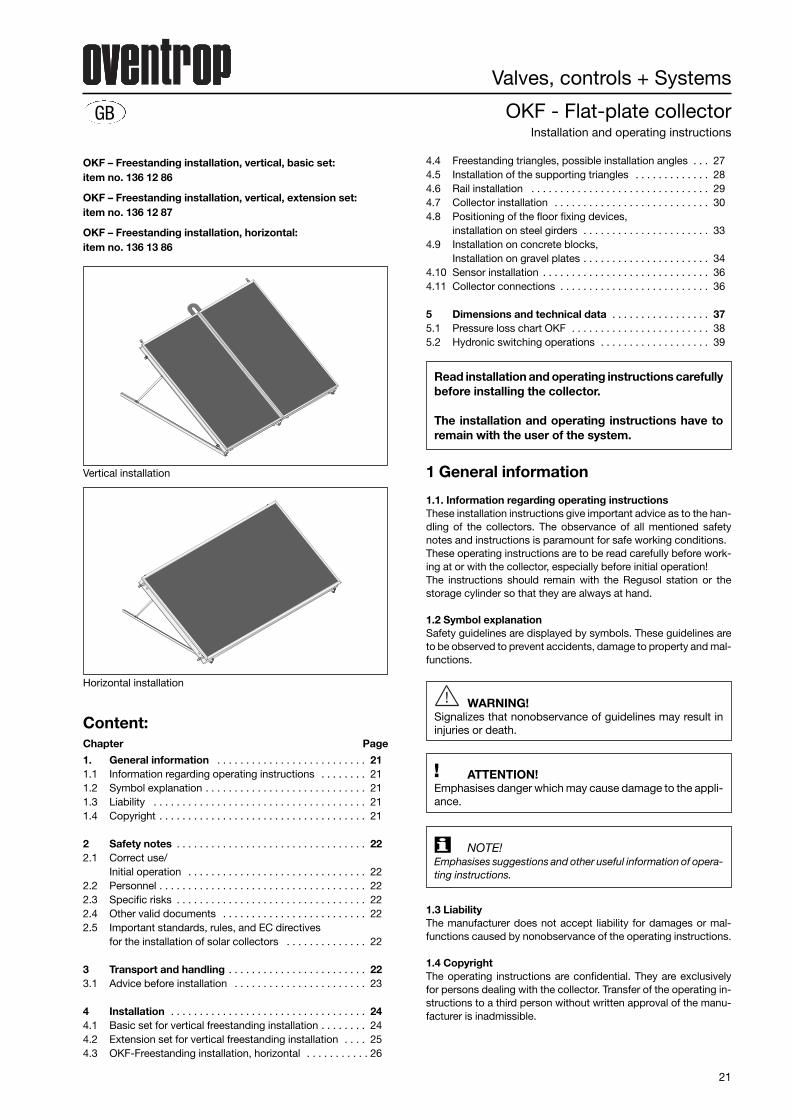
OKF – Freestanding installation, vertical, basic set:item no. 136 12 86
OKF – Freestanding installation, vertical, extension set:item no. 136 12 87
OKF – Freestanding installation, horizontal:item no. 136 13 86
GB
Vertical installation
Content:Chapter Page
1. General information . . . . . . . . . . . . . . . . . . . . . . . . . . 211.1 Information regarding operating instructions . . . . . . . . 211.2 Symbol explanation . . . . . . . . . . . . . . . . . . . . . . . . . . . . 211.3 Liability . . . . . . . . . . . . . . . . . . . . . . . . . . . . . . . . . . . . . 211.4 Copyright . . . . . . . . . . . . . . . . . . . . . . . . . . . . . . . . . . . . 21
2 Safety notes . . . . . . . . . . . . . . . . . . . . . . . . . . . . . . . . . 222.1 Correct use/
Initial operation . . . . . . . . . . . . . . . . . . . . . . . . . . . . . . . 222.2 Personnel . . . . . . . . . . . . . . . . . . . . . . . . . . . . . . . . . . . . 222.3 Specific risks . . . . . . . . . . . . . . . . . . . . . . . . . . . . . . . . . 222.4 Other valid documents . . . . . . . . . . . . . . . . . . . . . . . . . 222.5 Important standards, rules, and EC directives
for the installation of solar collectors . . . . . . . . . . . . . . 22
3 Transport and handling . . . . . . . . . . . . . . . . . . . . . . . . 223.1 Advice before installation . . . . . . . . . . . . . . . . . . . . . . . 23
4 Installation . . . . . . . . . . . . . . . . . . . . . . . . . . . . . . . . . . 244.1 Basic set for vertical freestanding installation . . . . . . . . 244.2 Extension set for vertical freestanding installation . . . . 254.3 OKF-Freestanding installation, horizontal . . . . . . . . . . . 26
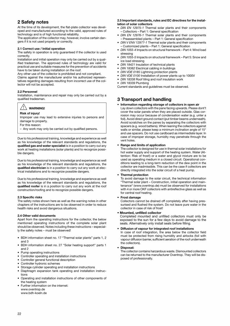
Horizontal installation
4.4 Freestanding triangles, possible installation angles . . . 274.5 Installation of the supporting triangles . . . . . . . . . . . . . 284.6 Rail installation . . . . . . . . . . . . . . . . . . . . . . . . . . . . . . . 294.7 Collector installation . . . . . . . . . . . . . . . . . . . . . . . . . . . 304.8 Positioning of the floor fixing devices,
installation on steel girders . . . . . . . . . . . . . . . . . . . . . . 334.9 Installation on concrete blocks,
Installation on gravel plates . . . . . . . . . . . . . . . . . . . . . . 344.10 Sensor installation . . . . . . . . . . . . . . . . . . . . . . . . . . . . . 364.11 Collector connections . . . . . . . . . . . . . . . . . . . . . . . . . . 36
5 Dimensions and technical data . . . . . . . . . . . . . . . . . 375.1 Pressure loss chart OKF . . . . . . . . . . . . . . . . . . . . . . . . 385.2 Hydronic switching operations . . . . . . . . . . . . . . . . . . . 39
22
2 Safety notesAt the time of its development, the flat-plate collector was devel-oped and manufactured according to the valid, approved rules oftechnology and is of high functional reliability.The application of the collector may, however, involve certain dan-gers if it is not used properly or correctly.
2.1 Correct use / Initial operationThe safety in operation is only guaranteed if the collector is usedcorrectly. Installation and initial operation may only be carried out by a qual-ified tradesman. The approved rules of technology are valid forpractical use and suitable measures for the prevention of accidentshave to be taken during installation on the roof.Any other use of the collector is prohibited and not compliant.Claims against the manufacturer and/or his authorized represen -tatives regarding damages resulting from incorrect use of the col-lector will not be accepted.
2.2 PersonnelInstallation, maintenance and repair may only be carried out by aqualified tradesman.
WARNING!
Risk of injury!Improper use may lead to extensive injuries to persons anddamage to property.For this reason:– Any work may only be carried out by qualified persons.
Due to his professional training, knowledge and experience as wellas his knowledge of the relevant standards and regulations, thequalified gas and water specialist is in a position to carry out anywork at heating installations (solar plants) and to recognize possi-ble dangers.
Due to his professional training, knowledge and experience as wellas his knowledge of the relevant standards and regulations, thequalified electrician is in a position to carry out any work at elec-trical installations and to recognize possible dangers.
Due to his professional training, knowledge and experience as wellas his knowledge of the relevant standards and regulations, thequalified roofer is in a position to carry out any work at the roofconstruction/roofing and to recognize possible dangers.
2.3 Specific risksThe safety notes shown here as well as the warning notes in otherchapters of the instructions are to be observed in order to reducehealth risks and avoid dangerous situations.
2.4 Other valid documentsApart from the operating instructions for the collector, the belowmentioned operating instructions of the complete solar plantshould be observed. Notes including these instructions – especial-ly the safety notes – must be observed!
• BDH information sheet no. 17 “Thermal solar plants” parts 1, 2and 3
• BDH information sheet no. 27 “Solar heating support“ parts 1and 2
• Pump operating instructions • Controller operating and installation instructions • Controller general functional description • Controller hydronic schemes• Storage cylinder operating and installation instructions • Diaphragm expansion tank operating and installation instruc-
tions • Operating and installation instructions of other components of
the heating system• Further information on the internet:
www.oventrop.dewww.bdh-koeln.de
2.5 Important standards, rules and EC directives for the instal-lation of solar collectors • DIN EN 12975-1 Thermal solar plants and their components
– Collectors – Part 1: General specification• DIN EN 12976-1 Thermal solar plants and their components
– Preassembled plants – Part 1: General specification• DIN V ENV 12977-1 Thermal solar plants and their components
– Customized plants – Part 1: General specification• DIN 1055-4 Impacts on structural framework – Part 4: Wind load
stressing• DIN 1055-5 Impacts on structural framework – Part 5: Snow and
ice load stressing• DIN 18421 Insulation of technical plants• DIN 18382 Electrical cabling in buildings• DIN VDE 0185 Lightning protection plants• DIN VDE 0100 Installation of power plants up to 1000V• DIN 18338 Roof tiling and roof insulation work• DIN 18339 PlumbingCurrent standards and guidelines must be observed.
3 Transport and handling• Information regarding storage of collectors in open air
Lay down collectors with the pane facing upwards. Please dont’tcover the solar panels when they are placed outside. Glas cor-rosion may occur because of condensation water (e.g. unter afoil). Avoid direct ground contact (put timber beams underneath).Avoid scratches on the panes by separating the collectors withspacers (e.g. wood battens). When leaning the collectors againstwalls or similar, please keep a minimum inclination angle of 15°and use spacers. Do not use cardboard as intermediate layer. Incase of improper storage, humidity may penetrate through thevent holes.
• Range and limits of applicationThe collector is designed for use in thermal solar installations forhot water supply and support of the heating system. Water (At-tention: Risk of frost!) or a water and glycol mixture are to beused as operating medium in a closed circuit. Operational con-ditions leading to a long-term reduction of the dew point in thecollector are inadmissible. This can be the case if collectors aredirectly integrated into the solar circuit of a heat pump.
• Thermal protectionTo avoid damage to the solar circuit, the technical information“Thermal solar plant – Construction, initial operation and main-tenance“ (www.oventrop.de) must be observed for installationswith 4 or more OKF collectors with antireflective glass as well asfor central roof heating.
• Frost damageCollectors cannot be drained off completely after having pres-surised and flushed the system. Do not leave pure water in thecollector in case of risk of frost!
• Mounted, unfilled collector Completed mounted and unfilled collectors must only be
exposed to the sun for a few days to avoid damage to theseals. Alternatively only install seals before filling.
• Diffusion of vapour for integrated roof installationsIn case of roof integration, the area below the collector fieldmust be protected from rising humidity and airlocks (foil withvapour diffusion barrier, sufficient aeration of the roof underneaththe collectors).
• Disposal:The collector contains harzardous waste. Dismounted collectorscan be returned to the manufacturer Oventrop. They will be dis-posed of professionally.
23
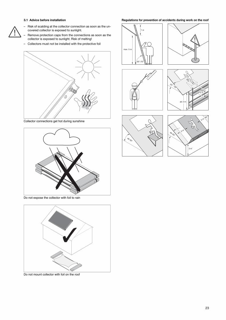
3.1 Advice before installation
– Risk of scalding at the collector connection as soon as the un-covered collector is exposed to sunlight.
– Remove protection caps from the connections as soon as thecollector is exposed to sunlight. Risk of melting!
– Collectors must not be installed with the protective foil
Regulations for prevention of accidents during work on the roof
!
Collector connections get hot during sunshine
Do not expose the collector with foil to rain
Do not mount collector with foil on the roof
24
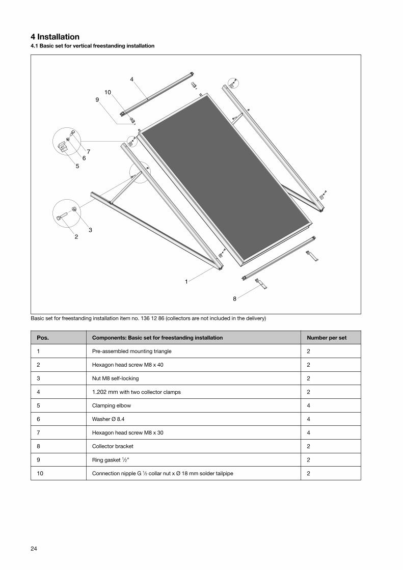
4 Installation4.1 Basic set for vertical freestanding installation
1
4
8
910
56
7
32
Basic set for freestanding installation item no. 136 12 86 (collectors are not included in the delivery)
Pos. Components: Basic set for freestanding installation Number per set
1 Pre-assembled mounting triangle 2
2 Hexagon head screw M8 x 40 2
3 Nut M8 self-locking 2
4 1.202 mm with two collector clamps 2
5 Clamping elbow 4
6 Washer Ø 8.4 4
7 Hexagon head screw M8 x 30 4
8 Collector bracket 2
9 Ring gasket 1⁄2" 2
10 Connection nipple G 1⁄2 collar nut x Ø 18 mm solder tailpipe 2
25
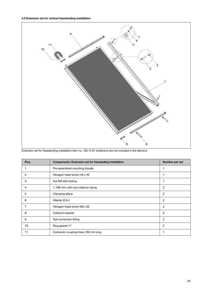
4.2 Extension set for vertical freestanding installation
4
56
7
32
1
9 8
11
10
Extension set for freestanding installation item no. 136 12 87 (collectors are not included in the delivery)
Pos. Components: Extension set for freestading installation Number per set
1 Pre-assembled mounting triangle 1
2 Hexagon head screw m8 x 40 1
3 Nut M8 self-locking 1
4 1.168 mm with one collector clamp 2
5 Clamping elbow 2
6 Washer Ø 8.4 2
7 Hexagon head screw M8 x 30 2
8 Collector bracket 2
9 Rail connection fitting 2
10 Ring gasket 1⁄2" 2
11 Connector coupling hose, 250 mm long 1
26
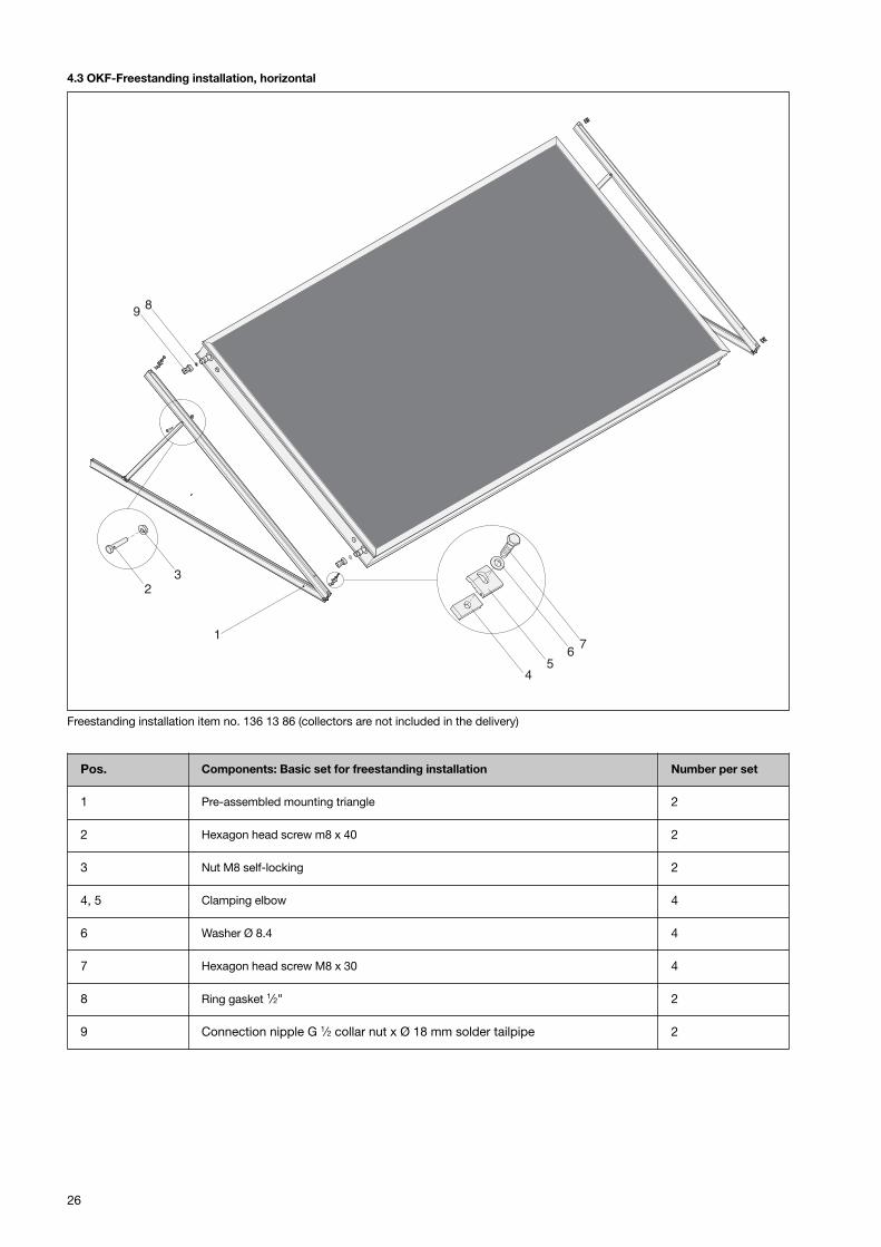
4.3 OKF-Freestanding installation, horizontal
Freestanding installation item no. 136 13 86 (collectors are not included in the delivery)
9 8
45
76
32
1
Pos. Components: Basic set for freestanding installation Number per set
1 Pre-assembled mounting triangle 2
2 Hexagon head screw m8 x 40 2
3 Nut M8 self-locking 2
4, 5 Clamping elbow 4
6 Washer Ø 8.4 4
7 Hexagon head screw M8 x 30 4
8 Ring gasket 1⁄2" 2
9 Connection nipple G 1⁄2 collar nut x Ø 18 mm solder tailpipe 2
27
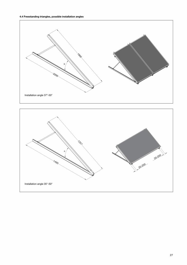
4.4 Freestanding triangles, possible installation angles
1900
2200
EURO TRIC F Hochformat für 37° - 50°Installation angle 37°-50°
1257
149020-2
00
20-200
Installation angle 35°-50°
28
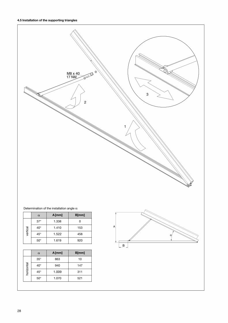
4.5 Installation of the supporting triangles
1
2
3
M8 x 40
Festlegen des Aufstellwinkels α
Tab. 4 Kollektortyp [°] C [mm] A [mm]
EURO TRIC F
Querformat
35° - 50°
alle EURO-Kollektortypen
35° 10 863
40° 147 940
45° 311 1.009
50° 521 1.070
EURO TRIC F
Hochformat
37° - 50°
EURO L20,EURO C20 undEURO C30
37° 0 1.471
40° 153 1.553
45° 458 1.679
50° 920 1.782
EURO L22,EURO C22 undEURO C32
37° 0 1.338
40° 153 1.410
45° 458 1.522
50° 920 1.619
A
C
� A [mm] B[mm]
vert
ical
37° 1.338 0
40° 1.410 153
45° 1.522 458
50° 1.619 920
Determination of the installation angle �
17 NM
� A [mm] B[mm]
horizonta
l
35° 863 10
40° 940 147
45° 1.009 311
50° 1.070 521
B
29
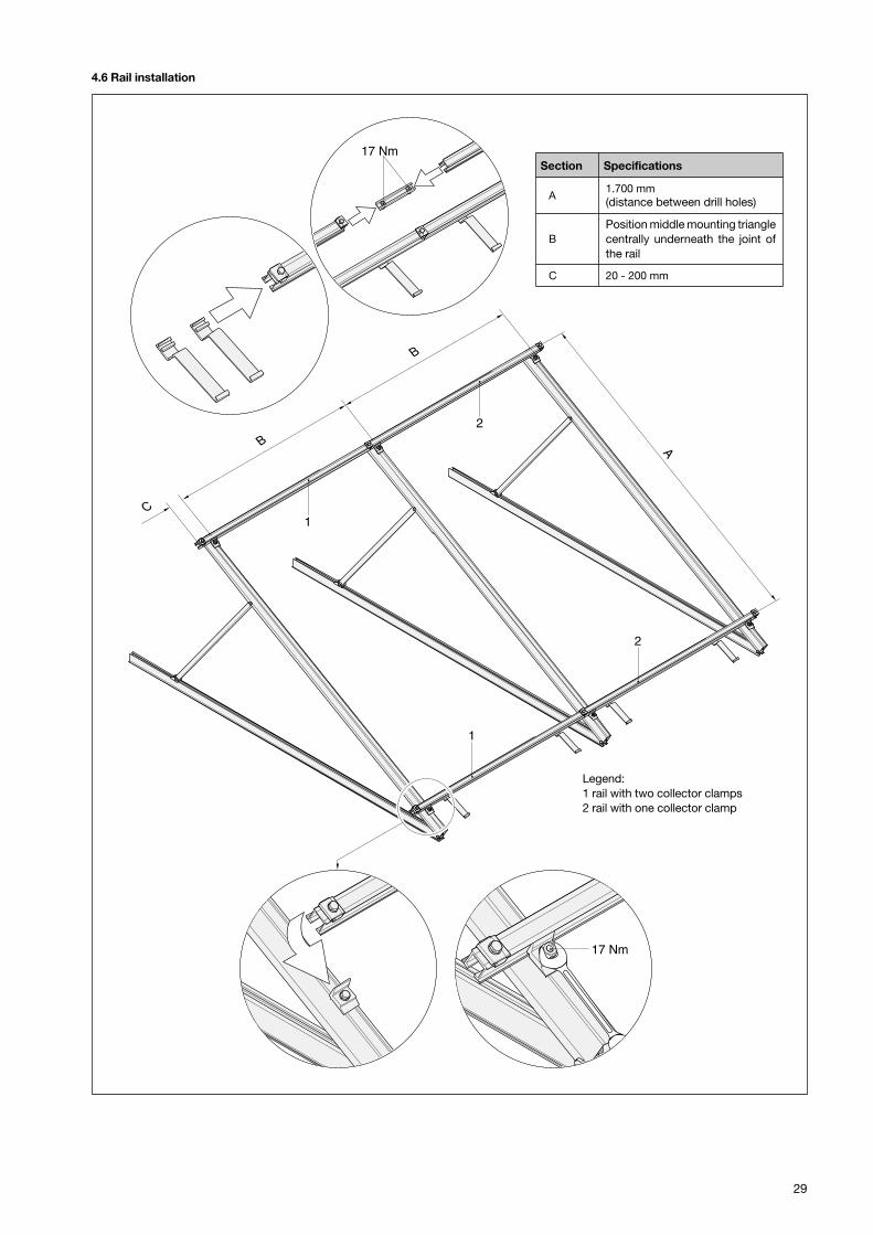
4.6 Rail installation
B
B
C
17 Nm
17 Nm
1
1
2
2
A
Legende:1 Schiene mit zwei Kollektorklemmen2 Schiene mit einer Kollektorklemme
Legend:1 rail with two collector clamps2 rail with one collector clamp
Section Specifications
A1.700 mm(distance between drill holes)
BPosition middle mounting trianglecentrally underneath the joint ofthe rail
C 20 - 200 mm

30
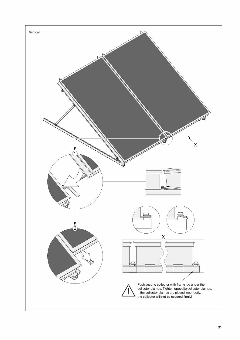
4.7 Collector installation
X
1
17 NmX
2
Kollektorklemme leicht lösen und nach außen schieben. An-schließend Kollektor aufbringen. Zum Schluss Kollektorklem-me an Kollektor heranschieben und festziehen. Falsch oderschlecht positionierte Kollektorklemmen können einen unge-nügenden Halt des Kollektors verursachen!
Loosen collector clamp slightly and push it to theoutside. Mount collector. Finally, push collectorclamp towards the collector and tighten. If the collectorclamps are placed incorrectly, the collector will notbe secured firmly!
Vertical
31
X
X
Zweiten Kollektor mit Rahmensteg auf einer Seite unterKollektorklemmen schieben. Auf der anderen Seite Kol-lektorklemmen festziehen. Falsch oder schlecht positio-nierte Kollektorklemmen können einen ungenügendenHalt des Kollektors verursachen!
Push second collector with frame lug under thecollector clamps. Tighten opposite collector clamps.If the collector clamps are placed incorrectly,the collector will not be secured firmly!
Vertical
32
X
X
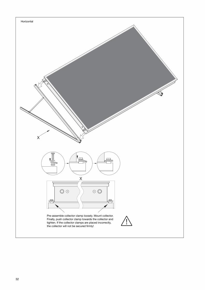
Pre-assemble collector clamp loosely. Mount collector.Finally, push collector clamp towards the collector andtighten. If the collector clamps are placed incorrectly,the collector will not be secured firmly!
Horizontal
33
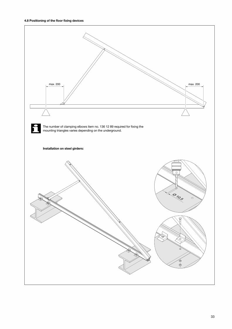
4.8 Positioning of the floor fixing devices
max. 200 max. 200
Ø 10,5
Die Anzahl der zur Fixierung der Aufstelldreiecke notwen-digen Klemmwinkel variiert je nach Untergrund. Informa-tionen erhalten Sie von unserem Technischen Innendienst.
Montage auf Stahlträgern
The number of clamping elbows item no. 136 12 89 required for fixing themounting triangles varies depending on the underground.
Installation on steel girders:
�
34
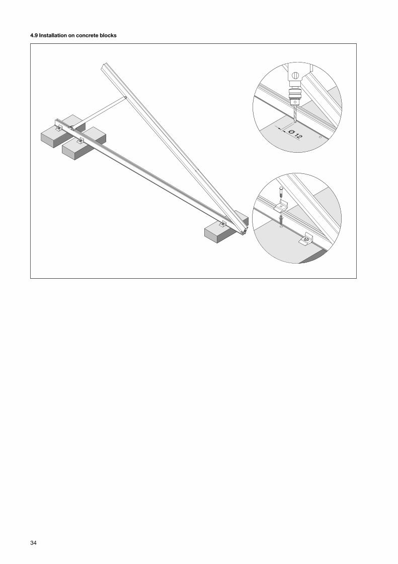
4.9 Installation on concrete blocks
Ø 12
35
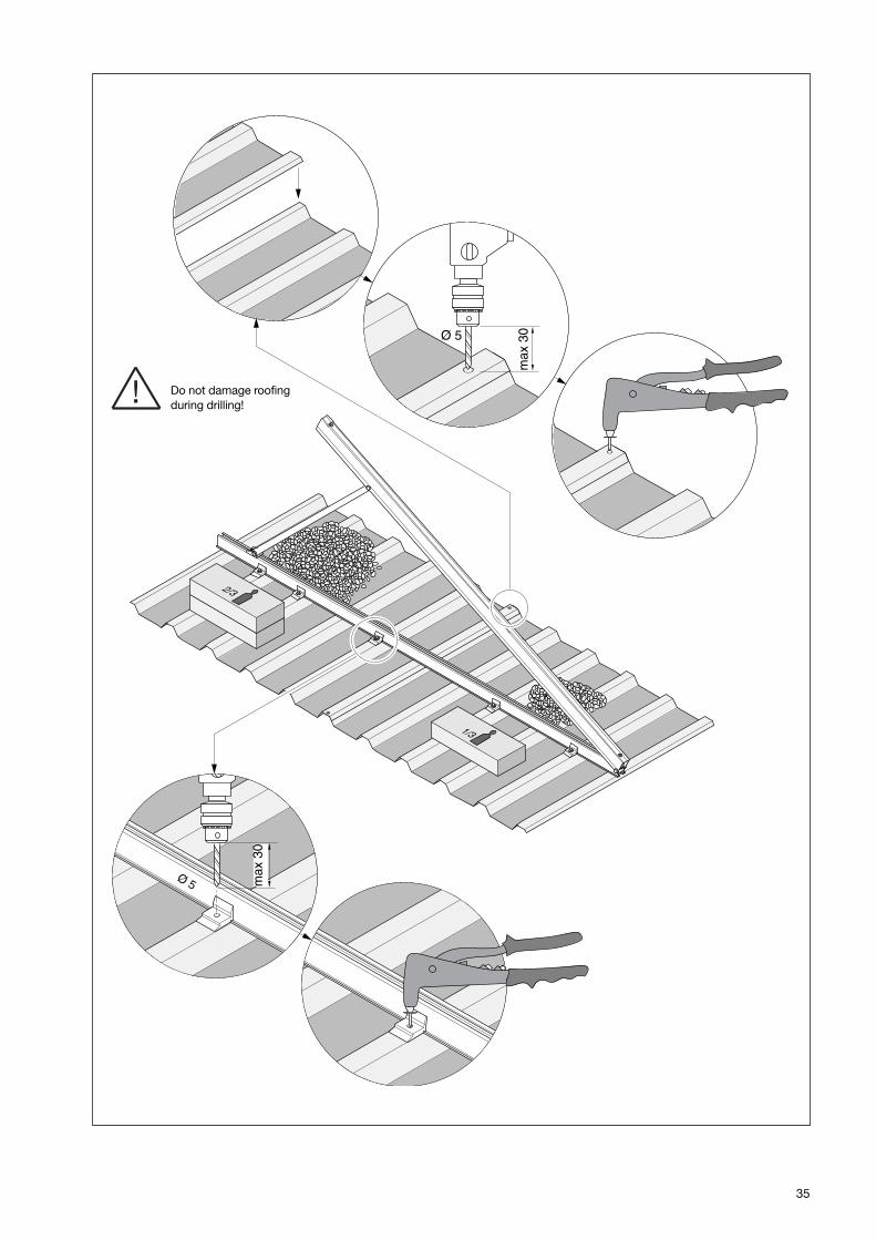
1/3
2/3
Ø 5 max
30
Ø 5
max
30
Do not damage roofingduring drilling!
36
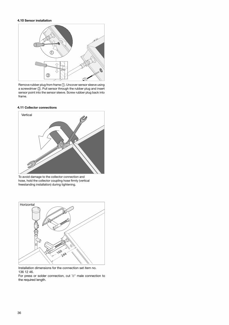
4.10 Sensor installation
Remove rubber plug from frame �. Uncover sensor sleeve usinga screwdriver �. Pull sensor through the rubber plug and insertsensor point into the sensor sleeve. Screw rubber plug back intoframe.
4.11 Collector connections
Vertical
To avoid damage to the collector connection and hose, hold the collector coupling hose firmly (verticalfreestanding installation) during tightening.
Horizontal
244160
Installation dimensions for the connection set item no.136 12 46.For press or solder connection, cut 1⁄2" male connection tothe required length.
�
�
37
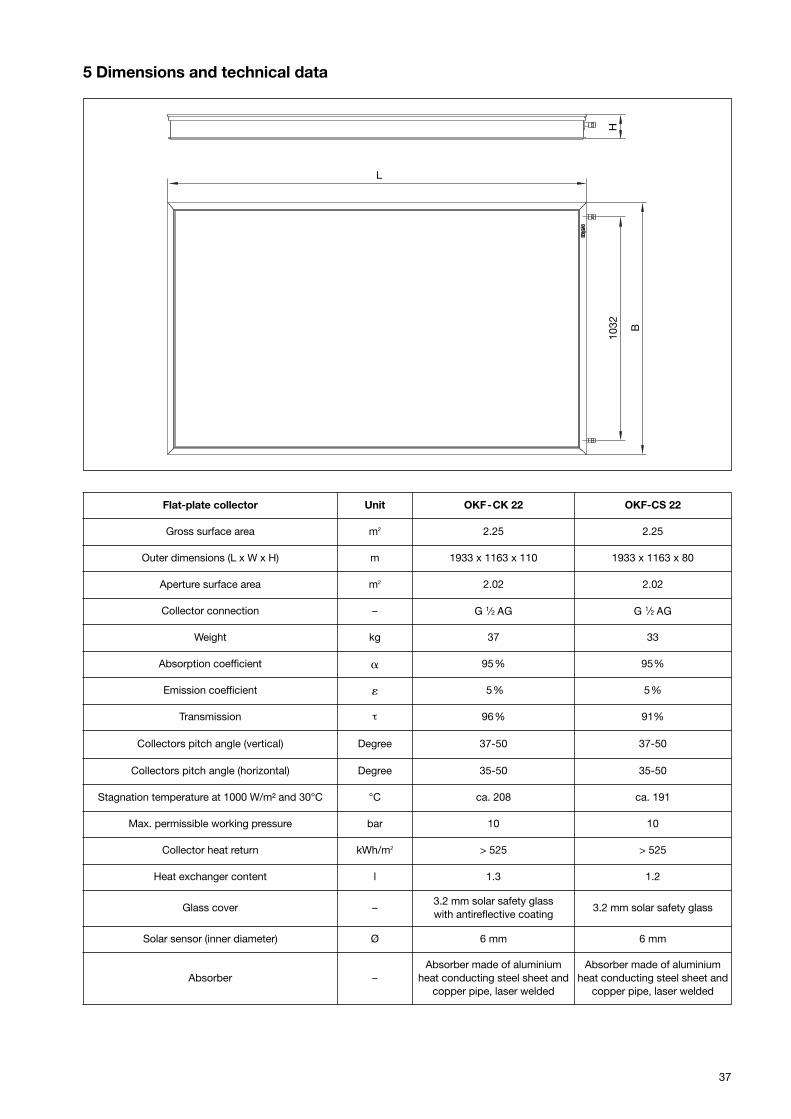
5 Dimensions and technical data
Flat-plate collector Unit OKF-CK 22 OKF-CS 22
Gross surface area m2 2.25 2.25
Outer dimensions (L x W x H) m 1933 x 1163 x 110 1933 x 1163 x 80
Aperture surface area m2 2.02 2.02
Collector connection – G 1⁄2 AG G 1⁄2 AG
Weight kg 37 33
Absorption coefficient � 95% 95%
Emission coefficient � 5% 5%
Transmission τ 96% 91%
Collectors pitch angle (vertical) Degree 37-50 37-50
Collectors pitch angle (horizontal) Degree 35-50 35-50
Stagnation temperature at 1000 W/m² and 30°C °C ca. 208 ca. 191
Max. permissible working pressure bar 10 10
Collector heat return kWh/m2 > 525 > 525
Heat exchanger content l 1.3 1.2
Glass cover –3.2 mm solar safety glasswith antireflective coating
3.2 mm solar safety glass
Solar sensor (inner diameter) Ø 6 mm 6 mm
Absorber –Absorber made of aluminium
heat conducting steel sheet andcopper pipe, laser welded
Absorber made of aluminiumheat conducting steel sheet and
copper pipe, laser welded
H10
32 B
L
38
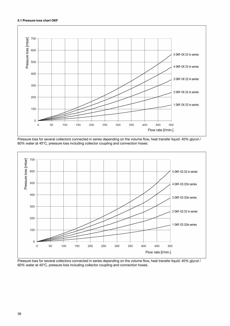
5.1 Pressure loss chart OKF
Pre
ssur
e lo
ss [m
bar
]
Flow rate [l/min.]
5 OKF-CK 22 in series
4 OKF-CK 22 in series
3 OKF-CK 22 in series
2 OKF-CK 22 in series
1 OKF-CK 22 in series
Pressure loss for several collectors connected in series depending on the volume flow, heat transfer liquid: 40% glycol /60% water at 40°C, pressure loss including collector coupling and connection hoses.
Pre
ssur
e lo
ss [m
bar
]
Flow rate [l/min.]
Pressure loss for several collectors connected in series depending on the volume flow, heat transfer liquid: 40% glycol /60% water at 40°C, pressure loss including collector coupling and connection hoses.
5 OKF-CS 22 in series
4 OKF-CS 22in series
3 OKF-CS 22in series
2 OKF-CS 22 in series
1 OKF-CS 22in series
39
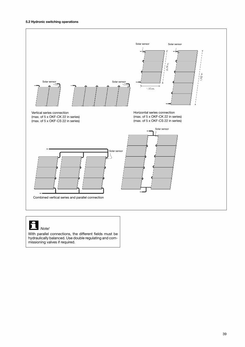
5.2 Hydronic switching operations
Vertical series connection(max. of 5 x OKF-CK 22 in series)(max. of 5 x OKF-CS 22 in series)
Horizontal series connection(max. of 5 x OKF-CK 22 in series)(max. of 5 x OKF-CS 22 in series)
Combined vertical series and parallel connection
Note!With parallel connections, the different fields must behydraulically balanced. Use double regulating and com-missioning valves if required.
�
Solar sensor Solar sensor
Solar sensor Solar sensor
Solar sensor
Solar sensor

40
For an overview of our global presencevisit www.oventrop.com.
Subject to technical modifications.
136128680 03/2012