valves made of gunmetal and stainless steel - kemper-olpe.de · 1 valves made of gunmetal and...
TRANSCRIPT
1
Valves made of gunmetal and stainless steel
Drinking water hygiene and corrosion resistance without compromise
High quality is our standard · since 1864
Valves
2
Valves
Table of contents
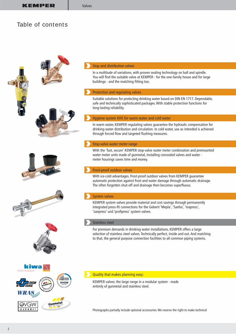
Stop and distribution valves
Protection and regulating valves
Hygiene system KHS for warm water and cold water
Stop-valve water meter range
Frost-proof outdoor valves
System valves
Stainless steel
Quality that makes planning easy:
KEMPER valves: the large range in a modular system - madeentirely of gunmetal and stainless steel.
For premium demands in drinking water installations, KEMPER offers a largeselection of stainless steel valves. Technically perfect, inside and out. And matching to that, the general purpose connection facilities to all common piping systems.
KEMPER system valves provide material and cost savings through permanentlyintegrated press-fi t connections for the Geberit ‘Mepla‘, ‘Sanha‘, ‘mapress‘,‘sanpress‘ und ‘profi press‘ system valves.
With ice-cold advantages. Frost-proof outdoor valves from KEMPER guarantee automatic protection against frost and water damage through automatic drainage. The often forgotten shut-off and drainage then becomes superfl uous.
With the ’fast, secure’ KEMPER stop-valve water meter combination and premountedwater meter units made of gunmetal, installing concealed valves and water -meter housings saves time and money.
In warm water, KEMPER regulating valves guarantee the hydraulic compensation fordrinking water distribution and circulation. In cold water, use as intended is achievedthrough forced fl ow and targeted fl ushing measures.
Suitable solutions for protecting drinking water based on DIN EN 1717. Dependable,safe and technically sophisticated packages. With stable protection functions forlong-lasting reliability.
In a multitude of variations, with proven sealing technology on ball and spindle.You will fi nd the suitable valve at KEMPER - for the one-family house and for largebuildings - and the matching fi tting too.
Photographs partially include optional accessories. We reserve the right to make technical

High quality is our standard · since 1864 3
Valves
Contact person / Training
Insulating
Shipbuilding / Industrial valves
Stainless steel valves – noble
System valves
Frost-proof outdoor valves and ‘Tresor‘ wall cupboards
Stop-valve water meter range
Hygiene system KHS for warm water and cold water
Protection and regulating valves
Stop and distribution valves
KEMPER gunmetal - the material
KEMPER valves made of gunmetal and stainless steelKEMPER lip seals
4
Kapitel
Valves made of gunmetal and stainless steel
Valves
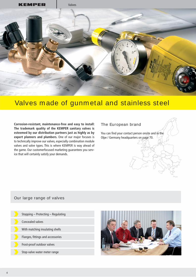
Corrosion-resistant, maintenance-free and easy to install: The trademark quality of the KEMPER sanitary valves is esteemed by our distribution partners just as highly as by expert planners and plumbers. One of our major focuses is to technically improve our valves, especially combination module valves and valve types. This is where KEMPER is way ahead of the game. Our customerfocused marketing guarantees you serv-ice that will certainly satisfy your demands.
The European brand
You can fi nd your contact person onsite and in the Olpe / Germany headquarters on page 70.
Our large range of valves
Stopping – Protecting – Regulating
Concealed valves
With matching insulating shells
Flanges, fi ttings and accessories
Frost-proof outdoor valves
Stop-valve water meter range

High quality is our standard · since 1864 5
Advantages at a glance
Corrosion resistant; made of gunmetal according to DIN 50930/6 (EN 1982) and stainless steel
With self-lubricating EPDM lip seals that can be replaced under pressure as a maintenance-free spindle sealing
DVGW, SVGW, ÖVGW, KIWA, WRAS and soundproofi ng certifi cate
Stagnant-zone-free
Connection facilities for all common piping systems
Gebr. Kemper GmbH + Co. KG, Olpe / Germany
KapitelValves
Plant I Plant II
KEMPER Technikum
Parking place

6
Valves
Quality awareness
In each individual step of our fabrication process, our products are tested, appraised and put through strict tests. At KEMPER, our employees live quality as an obligation. That means products emerge that you can count on, permanently.
KEMPER valves Protection andmaintenancefree for decades
Many promise protection for years. But only a few guarantee protection for decades. Starting immediately, you can specify KEMPER protection in your delivery specifi cation texts: „... Withself-lubricating EPDM lip seals that can be replaced underpressure as a maintenance-free spindle sealing“
Quality
Operatingcosts

High quality is our standard · since 1864 7
KEMPER – stagnant-zone-free head part - for us, just old hat
Absolutely stagnant-zone-free, making them hygienically safe because microbiology is impossible
With self-lubricating EPDM lip seals that can be replaced under pressure as a maintenance-free spindle sealing
Voluminous, self-lubricating, lower lying lip seal separates the spindle thread
Shock resistant and ergonomic, easily reachable handwheel
High-quality, dimensionally stable special seat sealing with high return force and extreme pressure and temperature stability
Head-part and housing material made completely of gunmetal and
corrosion resistant against aggressive water
Head part can be completely replaced and combined with standard valves for repairs
With DVGW and sound insulation
Materials compliant with CDW recommendations
10 year guaranty specifi cally for gunmetal stop valves, Figure 173
Protection is good. Long-term protection is better
Protection and freedom from maintenance for decades – there is no better reason for recommending KEMPER valves with the self-lubricating EPDM lip seals during bidding. Valves from KEM-PER provide many value added benefi ts when compared to other valves:
Valves
Lip seals
Grease

8
Gunmetal
KEMPER Gunmetal
KEMPER gunmetal -suitable for all types of drinking water
Old bronze ship‘s bells, artistic wine casks and other fi nds from the Bronze Age (from approx. 6000 BC.) impressively prove this material‘s unusual durability. And that‘s even true when the wit-nesses of this creative epoch have been laying in salty sea water for thousands of years. The gunmetal cast by KEMPER is a mate-rial closely related to bronze (copper and tin) and is extremely well suited for use in domestic water engineering, especially in drinking water and heating installations.Gunmetal is a material that can be used for all kinds of drinkingwater. The emission of alloying elements lies within the frame of the German drinking water regulations (German abbreviation: TrinkwV).
Due to its high Cu content, gunmetal has low dezincifi cation
According to the Drinking Water Quality Ordinance, gunmetal can be used without restrictions in all water qualities
Gunmetal is especially corrosion resistant
Gunmetal is extracted from recycling materials (old valves and components) without any loss of
quality, protecting the environment and conserving resources
That means gunmetal provides you with security! Now and in the future!
High quality is our standard · since 1864 9
Gunmetal
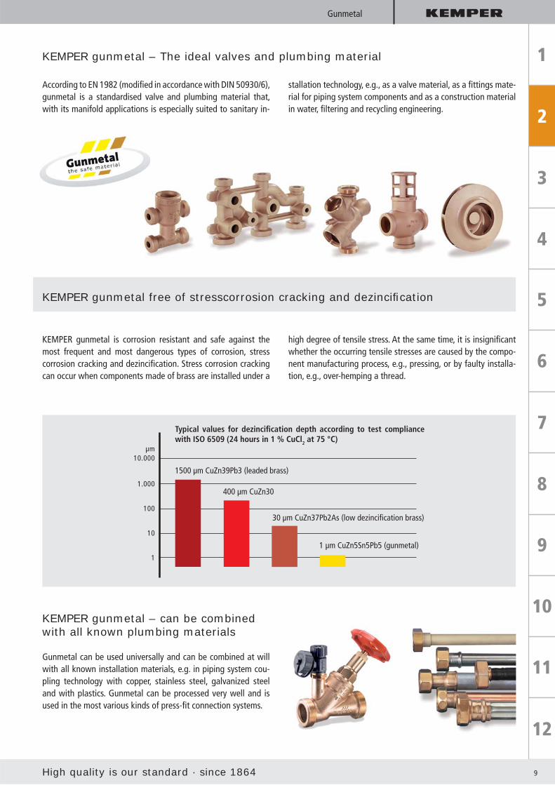
KEMPER gunmetal – The ideal valves and plumbing material
According to EN 1982 (modifi ed in accordance with DIN 50930/6), gunmetal is a standardised valve and plumbing material that, with its manifold applications is especially suited to sanitary in-
stallation technology, e.g., as a valve material, as a fi ttings mate-rial for piping system components and as a construction material in water, fi ltering and recycling engineering.
KEMPER gunmetal free of stresscorrosion cracking and dezincifi cation
KEMPER gunmetal is corrosion resistant and safe against the most frequent and most dangerous types of corrosion, stress corrosion cracking and dezincifi cation. Stress corrosion cracking can occur when components made of brass are installed under a
high degree of tensile stress. At the same time, it is insignifi cant whether the occurring tensile stresses are caused by the compo-nent manufacturing process, e.g., pressing, or by faulty installa-tion, e.g., over-hemping a thread.
KEMPER gunmetal – can be combinedwith all known plumbing materials
Gunmetal can be used universally and can be combined at will with all known installation materials, e.g. in piping system cou-pling technology with copper, stainless steel, galvanized steel and with plastics. Gunmetal can be processed very well and is used in the most various kinds of press-fi t connection systems.
Typical values for dezincifi cation depth according to test compliance with ISO 6509 (24 hours in 1 % CuCl2 at 75 °C)
1500 µm CuZn39Pb3 (leaded brass)
400 µm CuZn30
30 µm CuZn37Pb2As (low dezincifi cation brass)
1 µm CuZn5Sn5Pb5 (gunmetal)

10
Stop and distribution valves
KEMPER Stop and distribution valves
Completely made of gunmetal, resistant to aggressive water
With self-lubricating EPDM lip seals that can be replaced under pressure as a maintenance-free spindle sealing
NIRO seat with high-quality gasket ring
Stagnant-zone-free
DVGW and soundproofi ng certifi cate, versatile use through country-specifi c permits
Connection facilities for all common piping systems
Advantages at a glance
Secure against corrosion, perfect in coupling technology
KEMPER stop and distribution valves in various versions, made completely out of gunmetal. With proven sealing technology on the ball and spindle. KEMPER‘s wide range comes in a modu-lar system - for single-family houses or major projects - and the matching connection to boot.
Flanges or fi ttings as system valve ‘sanpress‘ and ‘profi press‘, ‘mapress‘, ‘Mepla‘ and ‘Sanha‘

High quality is our standard · since 1864 11
Stop and distribution valves
KEMPER Water Meter Mounting Accessories
Valves and fi ttings made completely of gunmetal with
integrated length compensation
Open, adjustable stainless steel bracket
Wall clearance adjustable from 92 - 132 mm
Water meter fi tting can be sealed
Various connection variants for every installation situation
With a 10 year guaranty
Be on the safe side. Trust trademark quality from KEMPER - made inGermany, from gunmetal, reliable and proven.
KEMPER free-fl ow stop valve with fl at-sealing external threads Figure 173
KEMPER water meter mounting accessories Figures 450
KEMPER free-fl ow stop valve with permanently cast Geberit ‘Mepla‘ connection Figure 190 41
KEMPER free-fl ow stop valves with permanently integrated press fi t ‘Sanha‘ Figure 190 36
KEMPER free-fl ow stop valveswith fl ange connection Figure 135
KEMPER double distributor setFigure V2
12
Protection valves
KEMPER Protection valves
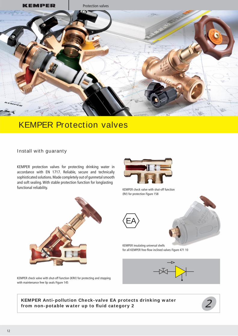
Install with guaranty
KEMPER protection valves for protecting drinking water in accordance with EN 1717. Reliable, secure and technically sophisticated solutions. Made completely out of gunmetal smooth and soft sealing. With stable protection function for longlastingfunctional reliability. KEMPER check valve with shut-off function
(RV) for protection Figure 158
KEMPER insulating universal shells for all KEMPER free-fl ow inclined valves Figure 471 10
KEMPER Anti-pollution Check-valve EA protects drinking water from non-potable water up to fl uid category 2
KEMPER check valve with shut-off function (KRV) for protecting and stopping with maintenance free lip seals Figure 145
EA

High quality is our standard · since 1864 13
Protection valves
Extremely streamlined design which reduces the required opening pressure to
a mere 10 mbar (Figure 145, 158, 159)
Suitable for circulation systems
With test instruments for prescribed function test on the anti-pollution check valve
With self-lubricating EPDM lip seals that can be replaced under pressure as a maintenance-free spindle sealing
DVGW and soundproofi ng regulations
KEMPER anti-pollution check valves with permanently integrated press fi t mapress Figure 193 22
KEMPER anti-pollution check valve with permanently integrated press fi t Viega Figure 195 31
Housing made entirely of gunmetal according to EN 1982
Interior components made of rustproof stainless steel and high quality plastics
Easy-to-replace cartridge
Simple handling
KEMPER Antipollution check-valve
KEMPER pipe disconnector CA
KEMPER pipe disconnector CA protects drinking water from non-potable water up to fl uid category 3
CAFigure 362
Advantages at a glance
Advantages at a glance

14
‘Fill-Matic‘
KEMPER ’Fill-Matic’
The new KEMPER Heating fi lling stations
Comfortable heating plant fi lling and refi lling through a permanent connection
Safe because standard-compliant and approved
Compact mounting type by integrating stopping, strainers, pressure reducing valves, manometers and the CA
pipe disconnector or BA backfl ow preventer
Constant refi ll pressure through integrated pressure reducing valve
Connection facility for all common piping systems
High-quality, in proven gunmetal quality, resistant against aggressive water
Simple servicing through integrated shut off
Proven insulation technology according to the requirements made by EnEV, (German Energy
Savings Act) Building Material Class 1
The new KEMPER ‘Fill-Matic 3‘ and ‘Fill-Matic 4‘ permanently and reliably con-nect the heating plant with the drinking water system. That makes fi lling and refi ll-ing permanently convenient and safe. The integrated safety devices reliably prevent drinking water from the heating plant from getting into the drinking water net-
work. So, heating plants can be protected without inhibitors up to fl uid category 3 or with inhibitors up to fl uid category 4 in accordance with European standard EN 1717. In warm drinking water systems, in-creasing scale build-up hinders the heat transmission and leads to undesired tem-perature increases on the heat transfer
surfaces. According to VDI 2035-1, soften-ing plants are to be provided in accord-ance with the capacity or corresponding to the total carbonate for the fi lling and supplemental water. If the softening plant is required, it can only be implemented us-ing the ‘Fill-Matic 4‘.

High quality is our standard · since 1864 15
SANITARYDrinking water
e. g. P1 = 3.0 bar
HEATINGHeating water
P2 = 1.5 bar
’Fill-Matic 3’or
’Fill-Matic 4’
‘Fill-Matic‘
KEMPER ’Fill-Matic 3’heater fi lling combination CA protects drinking water from non-potable water up to and including fl uid category 3
KEMPER ’Fill-Matic 4’heater fi lling combination BA protects drinking water from non-potable water up to and including fl uid category 4
Manometer
Heating plant with inhibitors
Figure 364
Figure 365
BA
CA pipe
Pressure reducing valve cartridge with integrated dirt trap
Cut-off
Heating plant without inhibitors
CA
Manometer
Backfl ow preventer
Pressure reducing valve cartridge with integrated dirt trap
Cut-off
’Fill-Matic 4’
’Fill-Matic 3’
Installation exampleaccording to EN 1717

16
KEMPER ’Protect’ Backfl ow Preventer BA
KEMPER ’Protect’ Backfl ow Preventer BA
The new DIN EN 1717
The new DIN EN 1717 stipulates a uniform standard for drinking water installations Europe-wide to protect drinking water from nonpotable water. This standard dif-ferentiates the application fi elds for pro-tection valves and defi nes the permissible fl uid categories. Along with water supply companies, especially the following design engineers and plumbers are exposed to a liability risk.
KEMPER provides you the safe, techni-cally mature solution for that:The new, patented KEMPER ’Protect’ back-fl ow preventer BA protects drinking water from nonpotable water up to and includ-ing fl uid category 4.
Price advantage through light weight, short length and integrated dirt trap
Differential-pressure controlled protection cartridge made from one assembly group contributing to easy
replacement for the specifi ed maintenance
System pressure dependent, no drain valve dripping during pressure fl uctuations
All parts that have contact with fl uid (drinking water) made of gunmetal or stainless steel
Stagnant-zone-free
Installation of the backfl ow preventer BA under the highest possible water level
DVGW-/SVGW certifi cate
BA
Figure 360

High quality is our standard · since 1864 17
KEMPER ’Protect’ Backfl ow Preventer BA
I. Neutral position (Under operating pressure)If no water is being withdrawn, the inputand output side RV and the drain valve are closed.
II. Flow position
If water is being withdrawn, the inputand output side RV and the drain valveare closed.
III. Isolation position
During backsiphonage, the input sidepressure falls. If the pressure difference between the precompression and medium pressure chamber is only a bit over 0.14 bar, the input side RV and the drain valvecloses.
KEMPER backfl ow preventer BA protects drinking water from non-potable water up to fl uid category 4
According to EN 1717, there is an obliga-tion to perform regular maintenance for the BA backfl ow preventer. Accordingly, an annual maintenance contract is to be con-cluded between the operating company and the plumber.
The integrated dirt trap and the differen-tial-pressure controlled protection car-tridge are easily removed by opening the head part.
The output-side anti-pollution check-valve can also be replaced as necessary by open-ing the head-part with a twist of the wrist. That makes maintenance fast and effort-less and is done in a jiffy.
Technically mature, that‘s why it‘s so safe: The KEMPER ’Protect’ - backfl ow preventer BA is based on an ingenious three-cham-
ber system with precompression, medium pressure and back pressure zones. The differential-pressure controls in the input
protection cartridges and the output anti-pollution check-valve (RV) ensure reliabil-ity and a high degree of protection.
Simple maintenance: Trust is good, control is better
The three chamber system

18
KEMPER ’Protect’ Backfl ow Preventer BA
DN A H(mm)
h(mm)
L(mm)
D(mm)
Weight(kg)
Operatingpressure
Operatingtemperature
Rated fl ow at 1 barpressure loss
15 G 3/4 235 143 135 50 1.5 PN 10 max. 60 °C 3.16 m3/h
20 G 1 235 143 140 50 1.55 PN 10 max. 60 °C 3.49 m3/h
25 G 11/4 235 143 146 50 1.65 PN 10 max. 60 °C 3.55 m3/h
32 G 11/2 267 163 180 50 2.28 PN 10 max. 60 °C 9.0 m3/h
40 G 13/4 324 178 226 70 4.6 PN 10 max. 60 °C 14.0 m3/h
50 G 23/8 318 172 230 70 5.3 PN 10 max. 60 °C 15.2 m3/h
KEMPER ’Protect’ Ideal operating values with low weight and short mounting types
The application areas
According to EN 1717, National Ap-pendix, the following devices and withdrawal points are to be pro-tected by a backfl ow preventer BA:
Swimming and bathing pools with preparation and disinfection
Chemical admixture appliance (disinfection agent or fertilizer)
Chemical cleaning appliance
Printing shop, reproduction plant, photograph operation,
fi lm developing machine
Bath lifter, openings and functional parts above bathing edge
Galvanic bath
Sterile water, production with disinfection
Heater fi lling appliance (water with inhibitors)
High-pressure cleaner with chemical admixture
Laboratory table, chemical lab
Softening/denitrifi cation plant, formalin disinfection (dialysis)
Sterilizers for carcinogenic material
Gas developer, e.g. acetylene
Boot washer
Installation according to EN 1717*
1 2 3 4Cut-off valve Strainer Backfl ow preventer Cut-off valve

High quality is our standard · since 1864 19
KEMPER ’Protect’ Backfl ow Preventer BA
Planning goal: Protection of thedrinking water, risk minimization
Own drinking water network
PublicDW-network
Central DW building connection room distribution network / other consumers
WC SProtection up to Fluid Category 2At least one backflow preventer or onevalve with a degree of protectionmust be used.
For direct connection:Protection using suitableprotection valves „S“ atRisk > Fluid Category 2
e.g. backflow preventer BA
Device machine, plant orwithdrawal point with
hazard risk according toFluid Category 3 - 4
EN 1717 Protection matrix of the protection devices
EN 1717
Protection deviceCan be used to protect the Protection device Fluid Categories
Group Type Description 1 2 3 4 5
A A Unhindered, free drainage x • • • •
B Free drainage with non-circular overfl ow (unrestricted) x • • • •
C Free drainage with ventilated immersion pipe and overfl ow x • • – –
D Free drain with injector x • • • •
F Free drain with circular overfl ow (restricted) x • • • –
G Free drain with overfl ow confi rmed with trial with under-pressure x • • – –
B APipe disconnector with controlled medium pressure zone corresponds to backfl ow
• • • • –
C A Pipe disconnector with different, non-controllable pressure zones • • • – –
D A Pipe ventilator in throughpass o o o – –
B Back siphonage Type A2 with movable parts o o o o –
C Back siphonage Type A1 with constant connection to atmosphere o o o o o
E A Controllable anti-pollution check-valve • • – – –
B Non-controllable anti-pollution check-valveOnly for certainhousehold uses
C Controllable double anti-pollution check-valve • • – – –
D Non-controllable double anti-pollution check-valveOnly for certainhousehold uses
G A Pipe disconnector, not fl ow-controlled • • • – –
B Pipe disconnector, fl ow controlled • • • • –
H A Hose connection with anti-pollution check-valve • • o – –
B Pipe ventilator for hose connections o o – – –
C Automatic changerOnly for certainhousehold uses
D Pipe ventilator for hose connections, combinedWith anti-pollution check-valve (valve)
• • o – –
L A Pressurized ventilator o o – – –
B Pressurized ventilator, combined with downstream anti-pollution check-valve • • o – –
Gen. note: Setups with atmospheric ventilation (e.g. AA, BA, CA, GA, GB,...) must not be installed if there is any risk of fl ooding.
• Covers the risk and/or protection valves permitted– Does not cover the risk and/or protection valves not permittedo Covers the risk only if p = atm x not applicable

20
’FK-4’
KEMPER ’FK-4’ Backfl ow Preventer BA Discharge Valve
The KEMPER ’FK-4’ for securing the drink-ing water installation up to fl uid category 4 is manufactured from the corrosion-resistant, durable and proven material gunmetal.
It is shut off before the backfl ow preventer BA cartridge and the discharge. That pre-vents water from leaking during periods of non-usage. The KEMPER ‘FK-4’ is available in the sizes DN 15, 20, 25 and 50.
In the sizes DN 15 and DN 20, the KEMPER ‘FK-4‘ are supplied with non-rising stems and closed, black rotary grips. In the sizes DN 25 and DN 50, the KEMPER ‘FK-4‘ come equipped with brown handwheels.
Figure 367 01 025Figure 367 01 015
Application fi elds
DN 15 and DN 20 for the domestic area
DN 25 and DN 50 for industry and trade, agriculture and gardening companies
for secure compliance with the requirements in DIN EN 1717 up to fl uid category 4
for installation in new buildings and for replacing unsuitable tap valves in the inventory
Protects the drinking water installation up to fl uid category 4Protection with a backfl ow preventer BA is always required in the following applications:
Softening plant / de-acidifi cation plant
Chemical admixture equipment
Chemical cleaning appliance
Printing machinery with hose connection
Film development machine
Electrolytic baths with hose connection
Heater fi lling appliances (with inhibitors)
Jet cleaners with chemical feed in private sector, car washes, farmsteads, etc.
Portable laboratory benches
Boot washer
Surface irrigation plants, portable
High quality is our standard · since 1864 21
Advantages at a glance
‘FK-4‘
Background information from ordinances and standards
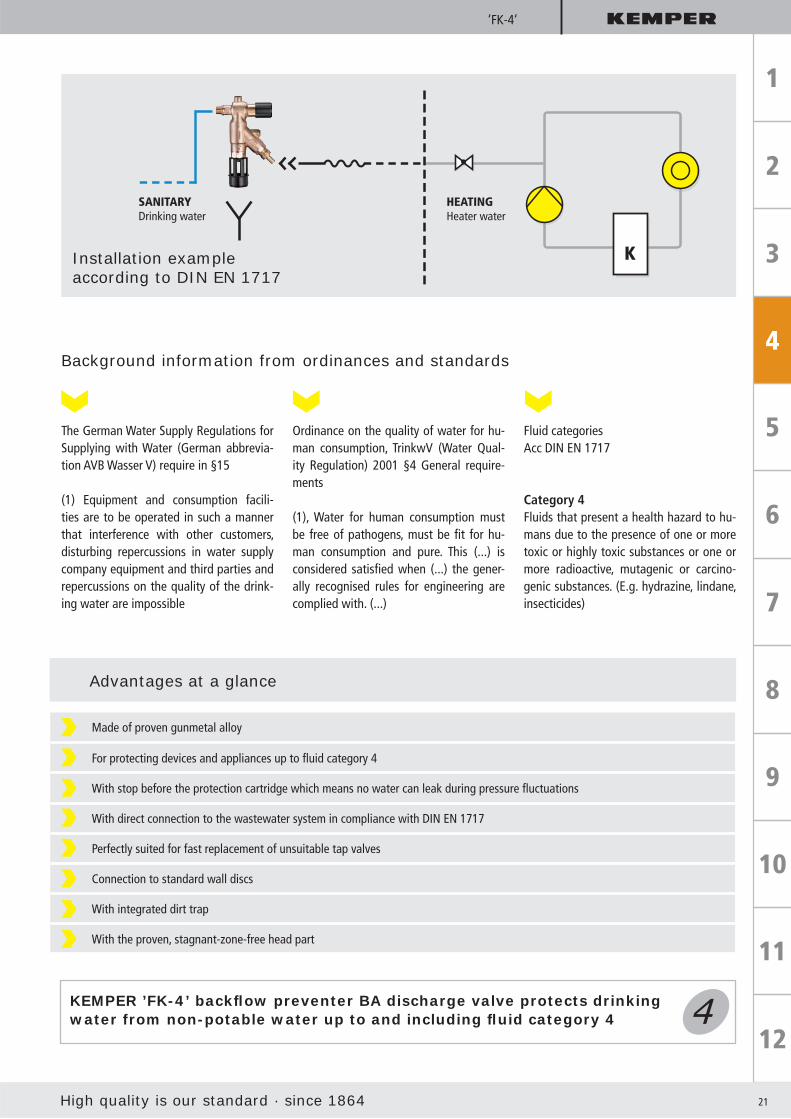
The German Water Supply Regulations for Supplying with Water (German abbrevia-tion AVB Wasser V) require in §15
(1) Equipment and consumption facili-ties are to be operated in such a manner that interference with other customers, disturbing repercussions in water supply company equipment and third parties and repercussions on the quality of the drink-ing water are impossible
Ordinance on the quality of water for hu-man consumption, TrinkwV (Water Qual-ity Regulation) 2001 §4 General require-ments
(1), Water for human consumption must be free of pathogens, must be fi t for hu-man consumption and pure. This (...) is considered satisfi ed when (...) the gener-ally recognised rules for engineering are complied with. (...)
Fluid categoriesAcc DIN EN 1717
Category 4Fluids that present a health hazard to hu-mans due to the presence of one or more toxic or highly toxic substances or one or more radioactive, mutagenic or carcino-genic substances. (E.g. hydrazine, lindane, insecticides)
Made of proven gunmetal alloy
For protecting devices and appliances up to fl uid category 4
With stop before the protection cartridge which means no water can leak during pressure fl uctuations
With direct connection to the wastewater system in compliance with DIN EN 1717
Perfectly suited for fast replacement of unsuitable tap valves
Connection to standard wall discs
With integrated dirt trap
With the proven, stagnant-zone-free head part
KEMPER ’FK-4’ backfl ow preventer BA discharge valve protects drinking water from non-potable water up to and including fl uid category 4
Installation example according to DIN EN 1717
SANITARYDrinking water
HEATINGHeater water
22
Category 1
Category 2
Category 3
Category 4
Category 5
KEMPER ’Protect’ Backfl ow Preventer BA
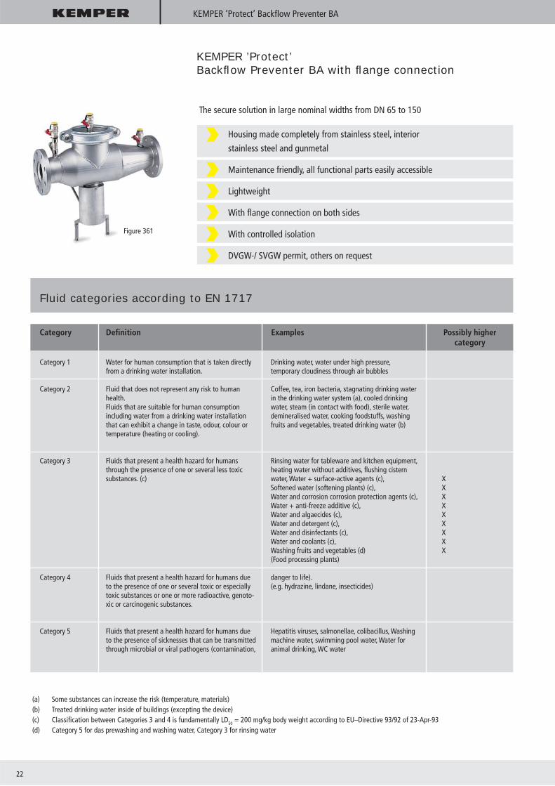
KEMPER ’Protect’Backfl ow Preventer BA with fl ange connection
Housing made completely from stainless steel, interior
stainless steel and gunmetal
Maintenance friendly, all functional parts easily accessible
Lightweight
With fl ange connection on both sides
With controlled isolation
DVGW-/ SVGW permit, others on request
The secure solution in large nominal widths from DN 65 to 150
Figure 361
Fluid categories according to EN 1717
Category Defi nition Examples Possibly higher category
(a) Some substances can increase the risk (temperature, materials)(b) Treated drinking water inside of buildings (excepting the device)(c) Classifi cation between Categories 3 and 4 is fundamentally LD50 = 200 mg/kg body weight according to EU–Directive 93/92 of 23-Apr-93(d) Category 5 for das prewashing and washing water, Category 3 for rinsing water
Water for human consumption that is taken directlyfrom a drinking water installation.
Fluid that does not represent any risk to human health.Fluids that are suitable for human consumptionincluding water from a drinking water installation that can exhibit a change in taste, odour, colour ortemperature (heating or cooling).
Fluids that present a health hazard for humans through the presence of one or several less toxic substances. (c)
Fluids that present a health hazard for humans due to the presence of one or several toxic or especially toxic substances or one or more radioactive, genoto-xic or carcinogenic substances.
Fluids that present a health hazard for humans due to the presence of sicknesses that can be transmittedthrough microbial or viral pathogens (contamination,
Drinking water, water under high pressure,temporary cloudiness through air bubbles
Coffee, tea, iron bacteria, stagnating drinking water in the drinking water system (a), cooled drinking water, steam (in contact with food), sterile water, demineralised water, cooking foodstuffs, washing fruits and vegetables, treated drinking water (b)
Rinsing water for tableware and kitchen equipment,heating water without additives, fl ushing cisternwater, Water + surface-active agents (c),Softened water (softening plants) (c), Water and corrosion corrosion protection agents (c),Water + anti-freeze additive (c),Water and algaecides (c),Water and detergent (c),Water and disinfectants (c),Water and coolants (c),Washing fruits and vegetables (d) (Food processing plants)
danger to life).(e.g. hydrazine, lindane, insecticides)
Hepatitis viruses, salmonellae, colibacillus, Washingmachine water, swimming pool water, Water foranimal drinking, WC water
XXXXXXXXX

High quality is our standard · since 1864 23
KEMPER differential manometer
Membrane spring differential-pressure manometer (display up to 1 bar differential pressure)
With premounted pressure hoses
With ball valves for bleeding and targeted pre-compression reduction
Including adapters for toolless bolting to 1/4“ and 1/2“ test valves
Includes quick-release couplings for connection to the pressure
With back pressure manometer with quick release coupling to test the output side RVs
In practical aluminium case
For the prescribed annual maintenance according to EN 12729
For checking the functional safety of the backfl ow preventer
To determine the differential pressure between forward pressure and mediumpressure chamber
KEMPER Differential manometer for backfl ow preventer BA
KEMPER Differential manometer
Figure 360 99

24
Facility engineering module
KEMPER Module Program
Made completely of gunmetal, hygienically fl awless
Can be fl exibly combined with modular construction with basic fl ange for all function modules
Complete from DN 15 to DN 50
Parts that have contact with fl uid (drinking water) made of gunmetal and stainless steel
Advantages at a glance
High quality is our standard · since 1864 25
Facility engineering module
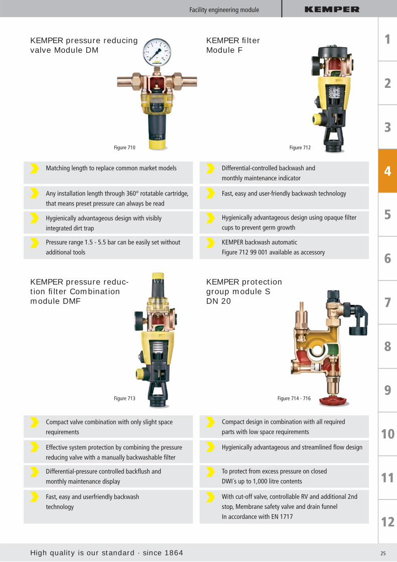
Matching length to replace common market models
Any installation length through 360° rotatable cartridge,
that means preset pressure can always be read
Hygienically advantageous design with visibly
integrated dirt trap
Pressure range 1.5 - 5.5 bar can be easily set without
additional tools
Differential-controlled backwash and
monthly maintenance indicator
Fast, easy and user-friendly backwash technology
Hygienically advantageous design using opaque fi lter
cups to prevent germ growth
KEMPER backwash automatic
Figure 712 99 001 available as accessory
Compact valve combination with only slight space
requirements
Effective system protection by combining the pressure
reducing valve with a manually backwashable fi lter
Differential-pressure controlled backfl ush and
monthly maintenance display
Fast, easy and userfriendly backwash
technology
Compact design in combination with all required
parts with low space requirements
Hygienically advantageous and streamlined fl ow design
To protect from excess pressure on closed
DWI´s up to 1,000 litre contents
With cut-off valve, controllable RV and additional 2nd
stop, Membrane safety valve and drain funnel
In accordance with EN 1717
KEMPER pressure reducing valve Module DM
KEMPER fi lter Module F
KEMPER pressure reduc-tion fi lter Combination module DMF
KEMPER protection group module S DN 20
Figure 710 Figure 712
Figure 713 Figure 714 - 716

26
Pressure reducing valve module DM
Parts that have contact with fl uid (drinking water) made of gunmetal and stainless steel
Fitting length to replace common market models
Fast, easy maintenance without needing to change the back pressure
Any desired installation position with 360° rotatable cartridge
Simple back pressure monitoring using the indicator scale or a manometer
Visible strainer integrated
Pressure range 1.5 - 6 bar can be preset without any tool
DVGW and WRAS certifi ed according to EN 1567
Expandable with modules for house water fi lter, pressure reducing valve/fi lter combination and protection group
KEMPER pressure reducing valve module DM: Advantages at a glance
Save water, limitpressure, protectthe system
Versatile couplingtechnology
Figure 710 0G Figure 710 08
Fast: Universal fi ttings forsoldering and pressing**
Safe: Made entirely of gunmetal
And suitable: For your calculation
* With nominal width reduction possible up to DN 25 (22 mm)** Comply with the processing instructions for system manufacturers
For pressing oncopper fi ttings
For pressing onstainless steel
For direct soldering ofcopper pipe*
For soldering oncopper solder fi ttings
High quality is our standard · since 1864 27
Pressure
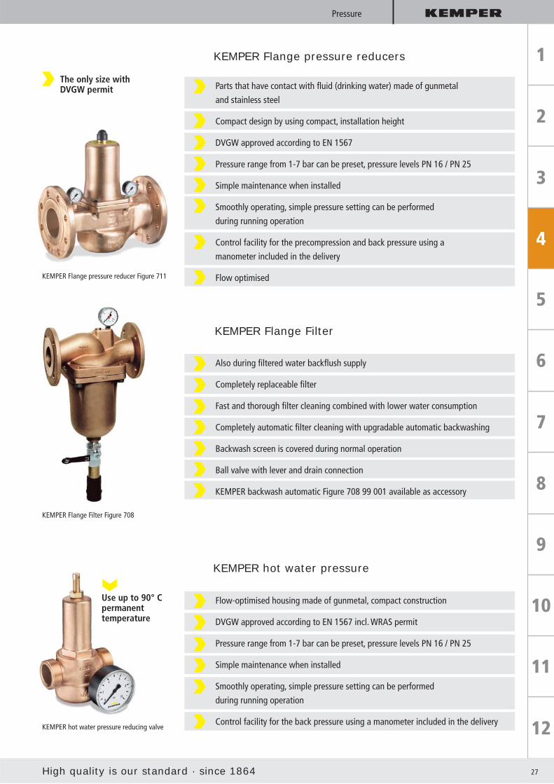
KEMPER Flange pressure reducers
Parts that have contact with fl uid (drinking water) made of gunmetal
and stainless steel
Compact design by using compact, installation height
DVGW approved according to EN 1567
Pressure range from 1-7 bar can be preset, pressure levels PN 16 / PN 25
Simple maintenance when installed
Smoothly operating, simple pressure setting can be performed
during running operation
Control facility for the precompression and back pressure using a
manometer included in the delivery
Flow optimisedKEMPER Flange pressure reducer Figure 711
KEMPER Flange Filter
Also during fi ltered water backfl ush supply
Completely replaceable fi lter
Fast and thorough fi lter cleaning combined with lower water consumption
Completely automatic fi lter cleaning with upgradable automatic backwashing
Backwash screen is covered during normal operation
Ball valve with lever and drain connection
KEMPER backwash automatic Figure 708 99 001 available as accessory
KEMPER Flange Filter Figure 708
KEMPER hot water pressure
Flow-optimised housing made of gunmetal, compact construction
DVGW approved according to EN 1567 incl. WRAS permit
Pressure range from 1-7 bar can be preset, pressure levels PN 16 / PN 25
Simple maintenance when installed
Smoothly operating, simple pressure setting can be performed
during running operation
Control facility for the back pressure using a manometer included in the deliveryKEMPER hot water pressure reducing valve
Use up to 90° Cpermanenttemperature
The only size withDVGW permit

28
Regulating valves
KEMPER Regulating valves
The threat from legionellas is growing.New TrinkwV water quality regulationsobligate to take action.
When the new drinking water regulations (TrinkwV 2001) cameinto effect on 01-Jan-03, existing tolerance limits were tightened. Moreover, compliance with the limits is required at the building entrance, rather than the tapping point. An importance change as compared with the old German water regulations is the periodic checks made on the building installations for legionella in public buildings. The recommended values listed in the DVGW Work-sheets will be maintained as the assessment basis. According to DVGW W 551, applicable is:
> 100 Legionellas (CFU/ml) Extremely high contaminationImmediate disinfection and restriction of use, shower prohibition, repairs are indicated
> 10 Legionellas (CFU/ml) High contaminationRepairs need to be made, hazard,possible restriction of use
0 Legionellas (CFU/ml) Target value No restrictions
If the target value 0 in 1 ml is not attained, take further actions on order of the health department according to § 20 (4). Health departments, as the offi cial government validation organ are en-
titled according to TrinkwV § 9 to order a shut-down of the water supply plant without ifs or buts when the limits and re-quirements are not complied with.
Water quality regulation based on the example of Germany according to TrinkwV 2001
Growth of legionella from a contaminated water sampleon a specifi c cultivation media (BCYE-α-agars)

High quality is our standard · since 1864 29
Regulating valves
Far reaching, painful consequences
Defective installations, stagnating water without tapping or withinsuffi ciently designed drinking water circulation systems (DWC), especially in large, extensive, warm water systems, cause illnesses and deaths in Germany through legionellas.
For that reason, every person who plans and executes must be aware of his/her responsibility before implementing drinking water systems, e.g. in hospitals, nursing homes, hotels, schools, administration buildings and large scale residential objects.
Each individual must examine the hazard potential specifi cal-ly for their building or object and develop a plant concept for implementation, operation and maintenance. When analysing germ-ridden plant systems, previously known types of potential hazards are repeated that alone or in interaction cause germina-tion in drinking water systems. Especially the following potential hazards are to be prevented:
Installation materials that emit nutrients usable by microorganisms
Setting up unnecessarily large warm water accumulator
Warm water temperature level, in which the bacteria growth is promoted (at TWDW < 50°C)
Hydraulic unbalanced warm water circulation systems and dead lines with stagnation manifestations
Hazard potentials
Tapping point buildingsection B (showers,taps etc.)
Tapping pointBuilding sectionA (showers,taps etc.)
Riser
Retu
rn c
ircul
atio
n 2
Warm water
Accumulator
! 5
! 5
Retu
rn c
ircul
atio
n 1
! 2
Heater
Cold water
Com
plet
e re
turn
!3
!1
!3
!4
30
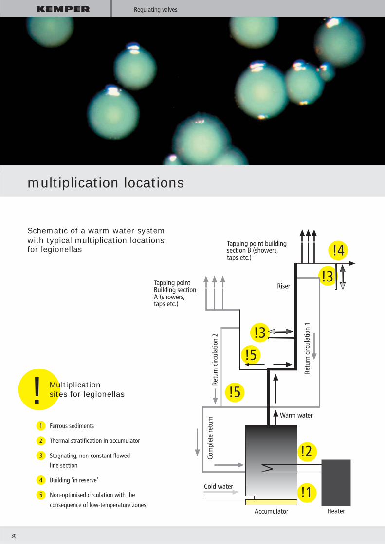
Schematic of a warm water system with typical multiplication locations for legionellas
! Multiplicationsites for legionellas
1 Ferrous sediments
2 Thermal stratifi cation in accumulator
3 Stagnating, non-constant fl owed
line section
4 Building ’in reserve’
5 Non-optimised circulation with the
consequence of low-temperature zones
Regulating valves
multiplication locations

High quality is our standard · since 1864 31
Regulating valves
Dimensioning the drinking water heating (DWH), distribution and circulation plant during new constructions and repairs needs to take not merely the function and economic, but also the drinking water hygienic aspects into account.
For this reason, the DVGW developed suitable dimensioning methods for dimensioning circulation systems. These are pub-lished in Worksheet W 553 “Dimensioning circulation systems in
central drinking water heating systems” as a technical rule with the publishing date 12/98.
The Work sheet W 553 replaces DIN 1988-3 in section 14. Mo-mentarily, the following computational verifi cations from the “Reference Works” for maintaining the drinking water quality in a professionally erected drinking water system are considered mandatory:
Implementation of the DVGW worksheets W 551, W 553
Consideration of the VDI Directive 6023
Maintaining drinking water hygiene in the warm drinking water system (WDW) based on the example of Germany
Dimensioning the line system for cold and heated water according to DIN 1988-3
dimensioning the circulation lines based on the DVGW worksheets W 551, W 553
Verifi cation of the water contents in non-circulating line sections
Laws, standards and directives
There are different standards, directives and laws in each country that protect the quality of drinking water and stipulate handling and transport in drinking water plants.

32
’Multi-Therm’
KEMPER ’Multi-Therm’ circulation regulating
Legionellacontrol
Be happy: When designing your next circulation system, for the fi rst time not everything revolves around the various valves, ther-mometers and connectors and the installation time needed for them. Instead, just use ‚Multi-Therm‘ valves from KEMPER and forget the rest.
The hygienists demand sterile warm water! The solution: KEMPER ’Multi-Therm’ valves for thermal disinfection. KEMPER supplies the proven and technically permanently im-proved range of regulating valves. Secure solutions for the drink-ing water distribution and circulation. Proven, best value, robust mode of operation. Regulation valves from KEMPER provide permanent protection against hazard po-
tentials that could arise due to the materials used, the stagnation and low temperature levels in the warm water system.
1 Thermostatic regulating unit
2 Stop unit with mount for thermometer or sensor
3 Movable emptying unit and G 3/4 hose connection
4 Measuring unit with thermometer or temperature sensor
+ Automatic thermal disinfection
Thermostatic-controlled regulation of the fi nest volume fl ows
Stopping and temperature monitoring in one head-part
Optimised emptying facility with a rotatable emptying valve
Optionally available with electronic temperature sensor for building control systems
High-quality in proven gunmetal quality, resistant to aggressive water
Stagnant-zone-free
DVGW, KIWA, ÖVGW, SVGW, WRAS certifi cate for plastic parts in contact with water
For nominal widths from DN 15 - DN 25
’Multi-Therm’: 4 + 1 in a compact system
High quality is our standard · since 1864 33
’Multi-Therm’
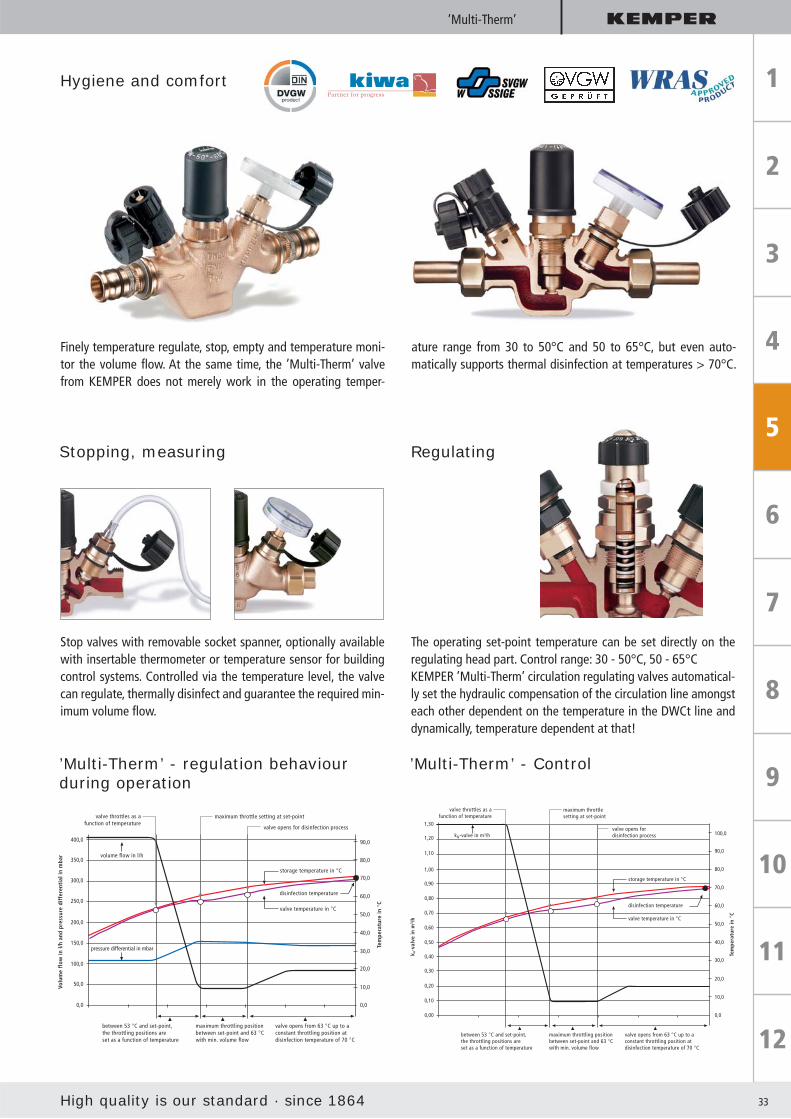
Hygiene and comfort
Finely temperature regulate, stop, empty and temperature moni-tor the volume fl ow. At the same time, the ’Multi-Therm’ valve from KEMPER does not merely work in the operating temper-
ature range from 30 to 50°C and 50 to 65°C, but even auto-matically supports thermal disinfection at temperatures > 70°C.
’Multi-Therm’ - regulation behaviour during operation
’Multi-Therm’ - Control
Stopping, measuring Regulating
Stop valves with removable socket spanner, optionally available with insertable thermometer or temperature sensor for building control systems. Controlled via the temperature level, the valve can regulate, thermally disinfect and guarantee the required min-imum volume fl ow.
The operating set-point temperature can be set directly on the regulating head part. Control range: 30 - 50°C, 50 - 65°CKEMPER ’Multi-Therm’ circulation regulating valves automatical-ly set the hydraulic compensation of the circulation line amongst each other dependent on the temperature in the DWCt line and dynamically, temperature dependent at that!
between 53 °C and set-point,the throttling positions areset as a function of temperature
350,0
300,0
250,0
200,0
150,0
100,0
50,0
0,0
maximum throttling positionbetween set-point and 63 °Cwith min. volume flow
valve opens from 63 °C up to aconstant throttling position atdisinfection temperature of 70 °C
0,0
10,0
20,0
30,0
40,0
50,0
60,0
70,0
80,0
Tem
pera
ture
in °
C
Volu
me
flow
in l/
h an
d pr
essu
re d
iffe
rent
ial i
n m
bar
valve throttles as afunction of temperature
maximum throttle setting at set-point
valve opens for disinfection process
storage temperature in °C
valve temperature in °C
volume flow in l/h
pressure differential in mbar
400,0 90,0
disinfection temperature
between 53 °C and set-point,the throttling positions areset as a function of temperature
0,90
0,70
0,60
0,50
0,40
0,20
0,10
0,00
maximum throttling positionbetween set-point and 63 °Cwith min. volume flow
valve opens from 63 °C up to aconstant throttling position atdisinfection temperature of 70 °C
0,0
Tem
pera
ture
in °
C
k v-v
alve
in m
3 /h
maximum throttlesetting at set-point
valve opens fordisinfection process
storage temperature in °C
disinfection temperature
valve temperature in °C
kv-valve in m3/h
1,00
0,30
0,80
10,0
20,0
30,0
40,0
50,0
60,0
70,0
80,0
valve throttles as afunction of temperature
1,20
1,30
1,10 90,0
100,0
34
’Eta-Therm’ fl oor regulating valve
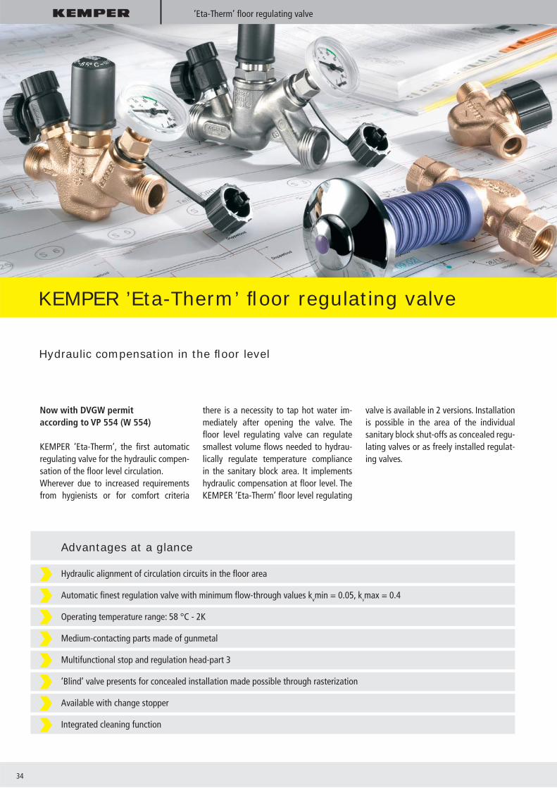
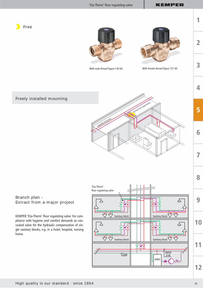
KEMPER ’Eta-Therm’ fl oor regulating valve
Hydraulic compensation in the fl oor level
Now with DVGW permitaccording to VP 554 (W 554)
KEMPER ’Eta-Therm’, the fi rst automatic regulating valve for the hydraulic compen-sation of the fl oor level circulation.Wherever due to increased requirements from hygienists or for comfort criteria
there is a necessity to tap hot water im-mediately after opening the valve. The fl oor level regulating valve can regulate smallest volume fl ows needed to hydrau-lically regulate temperature compliance in the sanitary block area. It implements hydraulic compensation at fl oor level. The KEMPER ’Eta-Therm’ fl oor level regulating
valve is available in 2 versions. Installation is possible in the area of the individual sanitary block shut-offs as concealed regu-lating valves or as freely installed regulat-ing valves.
Hydraulic alignment of circulation circuits in the fl oor area
Automatic fi nest regulation valve with minimum fl ow-through values kvmin = 0.05, kVmax = 0.4
Operating temperature range: 58 °C - 2K
Medium-contacting parts made of gunmetal
Multifunctional stop and regulation head-part 3
’Blind’ valve presents for concealed installation made possible through rasterization
Available with change stopper
Integrated cleaning function
Advantages at a glance
High quality is our standard · since 1864 35
’Eta-Therm’ floor regulating valve
D WWDW
suspended ceiling zone
’Eta-Therm’ fl oor regulating valve
Freely installed mounting
Branch plan - Extract from a major project
KEMPER ’Eta-Therm’ fl oor regulating valve. For com-pliance with hygiene and comfort demands as con-cealed valve for the hydraulic compensation of sin-gle sanitary blocks, e.g. in a hotel, hospital, nursing home.
’Eta-Therm’ fl oor regulating valve
Free
With male thread Figure 130 0G With female thread Figure 131 00
Sanitary block Sanitary block
Sanitary block Sanitary block
DWH
CDWWDWD W
36
’Multi-Fix’
KEMPER ’Multi-Fix’ circulation regulating valve
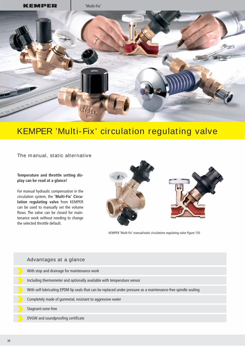
The manual, static alternative
Temperature and throttle setting dis-play can be read at a glance!
For manual hydraulic compensation in the circulation system, the ’Multi-Fix’ Circu-lation regulating valve from KEMPER can be used to manually set the volume fl ows. The valve can be closed for main-tenance work without needing to change the selected throttle default.
KEMPER ’Multi-Fix’ manual/static circulations regulating valve Figure 150
With stop and drainage for maintenance work
Including thermometer and optionally available with temperature sensor
With self-lubricating EPDM lip seals that can be replaced under pressure as a maintenance-free spindle sealing
Completely made of gunmetal, resistant to aggressive water
Stagnant-zone-free
DVGW and soundproofi ng certifi cate
Advantages at a glance

High quality is our standard · since 1864 37
Sampling valve
One sampling valve for all kinds of sampling
All parameters that need to be determined can be done at one single point
Sampling equipment is easy to use and fl ame treatable
Stable, long outlet elbow made of stainless steel generates a pencil-thick, straight and focused water jet
With a hexagonal spanner, you can regulate the drain amount and stop the valve
Valve housing and outlet elbow can be rotated 360°, so they can be aligned in any direction
For building valves from DN 15 to DN 150 as G 1/4“ and G 3/8“ male thread designs
Valve housing made of gunmetal or stainless steel
Housing can be fl amed as there are metal seals in the rotatable housing area
High quality, hygienically safe PTFE seat seal
Lower costs throughprofessional sampling
Operating companies that provide water to the public are obligated to verify fl aw-less quality. In order to do that, drinking water inspections need to be performed.
But in reality, there usually are not any suitable tapping points at these places, so sampling costs unnecessary extra time and cannot always be performed profes-sionally.
Sampling -simple, safe, reliable
KEMPER sampling valves for determining chemical and microbiological parameters in drinking, bathing and swimming pool water.

38
’Control-plus’
KEMPER ’Control-plus’ Flow and temperature measurement valve
KEMPER ’Control-plus’ - helps you work quickly and precisely
KEMPER ’Control-plus’:Flow and temperature measurement sensor Figure 138 4G withHand-held measuring instrument Figure 138 00 002,Sensor measuring module 138 00 011,’Multi-Fix’ Figure 150 and sampling valve Figure 187
Finally, the often time-consuming and cost-intensive regulating needed in plants and pipeline systems has come to an end: The perfect solution is the KEMPER ’Control-plus’.
The valve together with the mobile hand-held measuring instru-ment gives you the right perspective and mercilessly uncovers existing disruptive factors. Volumetric fl ows can be precisely de-termined and adjusted and operating conditions can be docu-mented. That increases reliability when operating both new and existing plants.Regulating the required volume fl ows greatly improves the tem-perature presence at the tapping points. Regulating the circu-lation system by setting the volume fl ows and monitoring the temperatures facilitate utilization of the maximum possible en-ergy-savings potential.Achieve effective, time-saving system regulation by combining the measurement valve with KEMPER regulating valves, Figure 150. The sensor’s measurement data can be saved and easily read out at accessible measurement locations with the optionally available sensor measurement module.
High quality is our standard · since 1864 39
’Control-plus’ / ’Multi-T-Stück’
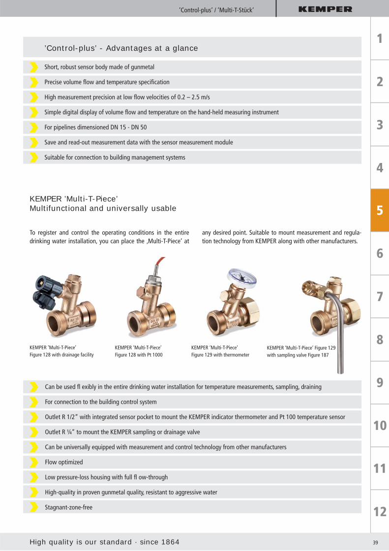
KEMPER ’Multi-T-Piece’Multifunctional and universally usable
To register and control the operating conditions in the entire drinking water installation, you can place the ‚Multi-T-Piece‘ at
any desired point. Suitable to mount measurement and regula-tion technology from KEMPER along with other manufacturers.
KEMPER ’Multi-T-Piece’Figure 128 with drainage facility
KEMPER ‘Multi-T-Piece’ Figure 129with sampling valve Figure 187
Short, robust sensor body made of gunmetal
Precise volume fl ow and temperature specifi cation
High measurement precision at low fl ow velocities of 0.2 – 2.5 m/s
Simple digital display of volume fl ow and temperature on the hand-held measuring instrument
For pipelines dimensioned DN 15 - DN 50
Save and read-out measurement data with the sensor measurement module
Suitable for connection to building management systems
’Control-plus’ - Advantages at a glance
KEMPER ’Multi-T-Piece’Figure 128 with Pt 1000
KEMPER ’Multi-T-Piece’Figure 129 with thermometer
Can be used fl exibly in the entire drinking water installation for temperature measurements, sampling, draining
For connection to the building control system
Outlet R 1/2“ with integrated sensor pocket to mount the KEMPER indicator thermometer and Pt 100 temperature sensor
Outlet R ¼“ to mount the KEMPER sampling or drainage valve
Can be universally equipped with measurement and control technology from other manufacturers
Flow optimized
Low pressure-loss housing with full fl ow-through
High-quality in proven gunmetal quality, resistant to aggressive water
Stagnant-zone-free
40
Hygiene System
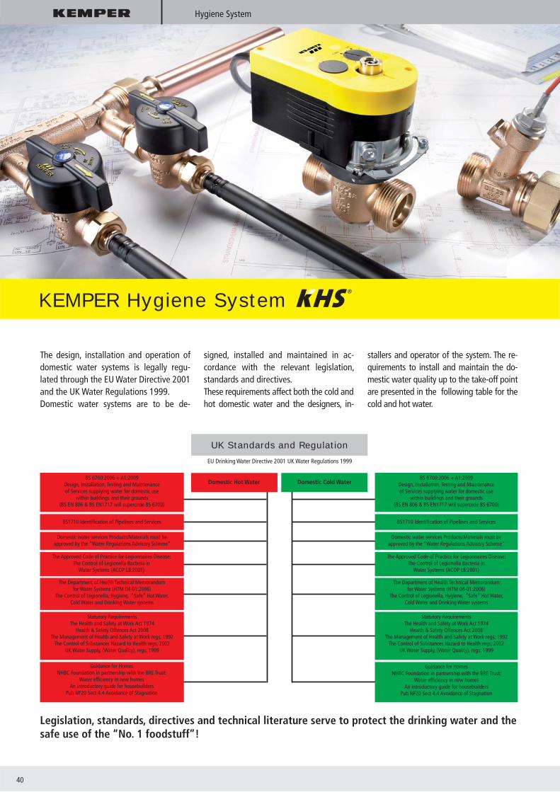
KEMPER Hygiene System
The design, installation and operation of domestic water systems is legally regu-lated through the EU Water Directive 2001 and the UK Water Regulations 1999.Domestic water systems are to be de-
signed, installed and maintained in ac-cordance with the relevant legislation, standards and directives.These requirements affect both the cold andhot domestic water and the designers, in-
stallers and operator of the system. The re-quirements to install and maintain the do-mestic water quality up to the take-off point are presented in the following table for the cold and hot water.
Legislation, standards, directives and technical literature serve to protect the drinking water and thesafe use of the “No. 1 foodstuff”!
UK Standards and Regulation
EU Drinking Water Directive 2001 UK Water Regulations 1999
Domestic Hot Water Domestic Cold WaterBS 6700:2006 + A1:2009
Design, Installation, Testing and Maintenance of Services supplying water for domestic use
within buildings and their grounds(BS EN 806 & BS EN1717 will supercede BS 6700)
BS1710 Identifi cation of Pipelines and Services
Domestic water services Products/Materials must be approved by the “Water Regulations Advisory Scheme”
The Approved Code of Practice for Legionnaires Disease: The Control of Legionella Bacteria in
Water Systems (ACOP L8:2001)
The Department of Health Technical Memorandum for Water Systems (HTM 04-01:2006)
The Control of Legionella, Hygiene, “Safe” Hot Water, Cold Water and Drinking Water systems
Statutory Requirements The Health and Safety at Work Act 1974
Health & Safety Offences Act 2008The Management of Health and Safety at Work regs; 1992
The Control of Substances Hazard to Health regs; 2002UK Water Supply, (Water Quality), regs; 1999
Statutory Requirements The Health and Safety at Work Act 1974
Health & Safety Offences Act 2008The Management of Health and Safety at Work regs; 1992
The Control of Substances Hazard to Health regs; 2002UK Water Supply, (Water Quality), regs; 1999
Guidance for HomesNHBC Foundation in partnership with the BRE Trust:
Water effi ciency in new homesAn introductory guide for housebuilders
Pub NF20 Sect 4.4 Avoidance of Stagnation
Guidance for HomesNHBC Foundation in partnership with the BRE Trust:
Water effi ciency in new homesAn introductory guide for housebuilders
Pub NF20 Sect 4.4 Avoidance of Stagnation
The Department of Health Technical Memorandum for Water Systems (HTM 04-01:2006)
The Control of Legionella, Hygiene, “Safe” Hot Water, Cold Water and Drinking Water systems
The Approved Code of Practice for Legionnaires Disease: The Control of Legionella Bacteria in
Water Systems (ACOP L8:2001)
BS 6700:2006 + A1:2009Design, Installation, Testing and Maintenance of Services supplying water for domestic use
within buildings and their grounds(BS EN 806 & BS EN1717 will supercede BS 6700)
BS1710 Identifi cation of Pipelines and Services
Domestic water services Products/Materials must be approved by the ”Water Regulations Advisory Scheme”

High quality is our standard · since 1864 41
Hygiene System
This is how plumbing was installed in the past
Up to now in residential, commercial and public buildings (hotels, hospitals, doctor‘s offi ces, etc.), potable water systems have been installed using T-pieces branching to the outlets. The consequential stagnation due to dead-legs in the branches is nothing unusual. In hot water systems the installa-tion of return lines, regulated by DRVs or thermally operated valves has already as-serted itself. However, remnant stagnation from after the return, to the outlet, still continues to exist. By looping in the outlet points as close as possible in a ring, the re-maining stagnation can also be prevented in the DHW system.
Conventional installation in DCW. With obvious dead-legs.Looping in the take-offs for DCW and DHW in a ring is recommended as the solution.
Normal installation in a single-family house with all the known weak points. Stagnation across decades with the consequential hy-giene and health risks can occur.
A better installation but still with weak points. Depending on the pipe lengths while looping, larger pipe sizes must be used, due to the fl ow requirement. How-ever, this solution is often not possible with conventional fl oor layouts.
DCW installation with stagnation in seldom-used lines. Branch line installation.
Reserved for future (? years stagnation)
Heating top-up line(? years stagnation)
Outdoor tap(approx 6 months stagnation)
Reserved for future (? years stagnation)
Larger pipe size due tolong pipe run.
Larger pipe sizedue to longpipe run.
DCW installation without stagnation in seldom-used lines. Long pipe run. Increased installation expense.

42
Hygiene System
Hygienically safe installation with KEMPER KHS Multi-Circ Distributor Units and in-novative pipe-runs.
DCW installation without dead-legs.
1
1
The KHS solution in DCW
KHS-Multi-Circ Distributor Unit
Reserved for future Normal operation is assumed
DCW installation without stagnation in seldom used sections. Minimisation of dead-legs.

High quality is our standard · since 1864 43
Hygiene System
The time controlled fl ushing process for the domestic cold water system using the preset fl ushing times(e.g. max. 5 fl ushing intervals across one day or individual fl ushing intervals on different days during a week).
The fl ow volume controlled fl ushing process for the domestic cold water using preset fl ushing volumes duringprogrammed fl ushing times.
The temperature controlled fl ushing process. Here, a reference temperature (e.g. on the DCW mainsconnection) is constantly compared with multiple temperatures in the system. The system control triggersfl ushing if the temperature difference exceeds the preset target temperature difference.
The operator can choose between three operating modes
Potable cold water hygiene by fl ushing end of line
Recommendation:In order to use the accruing fl ushed wa-ter, collect the water in a storage tank (e.g. rainwater harvesting systems, out-door rainwater facilities, etc).
One thing is for sure: a preventative strategy as opposed to a reactive strategy is the only correct one.
Apparatus
E.g. single tapping point
Storage, sprinkler system tank,Rainwater harvesting, etc.
KHS-full fl ow plus with spring-reset servo drive
KHS-Timer
2nd
1st
GF
Base
CDW
44
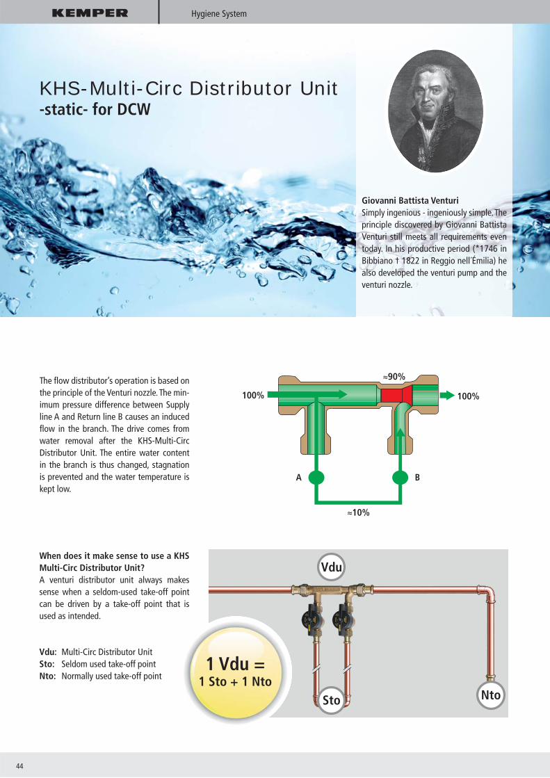
The fl ow distributor’s operation is based on the principle of the Venturi nozzle. The min-imum pressure difference between Supply line A and Return line B causes an induced fl ow in the branch. The drive comes from water removal after the KHS-Multi-Circ Distributor Unit. The entire water content in the branch is thus changed, stagnation is prevented and the water temperature is kept low.
Vdu
Sto Nto
When does it make sense to use a KHS Multi-Circ Distributor Unit?A venturi distributor unit always makes sense when a seldom-used take-off point can be driven by a take-off point that is used as intended.
Vdu: Multi-Circ Distributor UnitSto: Seldom used take-off pointNto: Normally used take-off point
Giovanni Battista VenturiSimply ingenious - ingeniously simple. The principle discovered by Giovanni Battista Venturi still meets all requirements even today. In his productive period (*1746 in Bibbiano † 1822 in Reggio nell´Émilia) he also developed the venturi pump and the venturi nozzle.
1 Vdu =1 Sto + 1 Nto
KHS-Multi-Circ Distributor Unit-static- for DCW
100%
WT WC
100%
10%
90%
A B
Hygiene System

High quality is our standard · since 1864 45
Ingeniously simple – simply dynamicSmall fl ows in the main – lots of movement in the branch ring.
With the KHS Multi-Circ Distributor Unit -dynamic-, another step towards stag-nation prevention has been achieved. With an additional component in the ven-turi nozzle, the dynamic distribution unit is capable of achieving a maximum fl ow through the connected branch rings; even with the smallest fl ow rates in the main or in the riser.
ExplanationDuring small fl ow in the main, ≈ 95 % fl ows through the ring!
Small volume fl ows in the main line or in the riser:The dynamic venturi nozzle remains nearly completely closed - nearly the entire fl ow needed for supply is driven through the ring. The opening pressure of the dynamic venturi nozzle is not reached.
KHS-Multi-Circ Distributor Unit-dynamic- for DCW
100%
WT WC
100%
95%
5%
5%
100%
WT WC
100%
10%
90%
90%
High volume fl ows in the main line or in the riser:The dynamic venturi nozzle opens - the majority of the fl ow passes directly through the fl ow distributor in the main line and a partial fl ow is diverted through the ring due to the venturi effect. The opening pressure of the dynamic venturi nozzle is reached.
KHS-Multi-Circ Distributor Unit -dynamic-
Hygiene System

46
Hygiene System
KHS-Multi-Circ Distributor UnitCharacteristics of KHS Multi-Circ Distributor Unit -static- and -dynamic-
The KHS Multi-Circ Distributor Unit -dy-namic- stands out from the well-known KHS Multi-Circ Distributor Unit -static- in that it reacts and operates ‘dynamically’. In the ‘Circulation’ function, the main is near-ly completely closed and the branch ring fl ows approx 95 % of the total. As the de-mand increases the fl ow increases to the point that the dynamic nozzle starts to open.
During higher demand, the main line is completely opened so that the fl ow re-quired further down the system, as well as the fl ow to cover the heat losses in the bathroom branches, is achieved.
Because of the previously described oper-ating principle, the KHS Multi- Circ Distrib-utor Unit -dynamic- can be used in both the DCW as well as in the DHW system with great effi ciency. Even at the lowest fl ow rates, a fl ow is induced in the branch ring due to the available differential pres-sure generated.
Prevent stagnation and maintain the temperature effectively
For DCW Constant water exchange Low temperature DCW system High volume fl ow in the branch ring Small volume fl ow in main
For DHW/DHWC Constant water exchange Due to the stable fl ow throughout the
system by branch ring circulation, and by demand, the temperature of the DHW is maintained as required, where required.
Diff
eren
tial
pre
ssur
e
Flow in main
Dynamic distributor unit
Static distributor unit
Consumption
=Static or dynamicdistributor unit
High quality is our standard · since 1864 47
Hygiene System
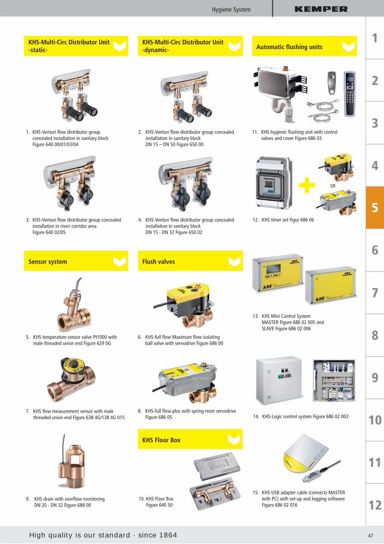
10. KHS Floor Box Figure 640 50
KHS Floor Box
1. KHS-Venturi fl ow distributor group concealed installation in sanitary block Figure 640 00/01/03/04
KHS-Multi-Circ Distributor Unit-static-
3. KHS-Venturi fl ow distributor group concealed installation in riser/ corridor area Figure 640 02/05
8. KHS-full fl ow-plus with spring-reset servodrive Figure 686 05
4. KHS-Venturi fl ow distributor group concealed installation in sanitary block DN 15 - DN 32 Figure 650 02
12. KHS timer set Figur 686 06
2. KHS-Venturi fl ow distributor group concealed installation in sanitary block DN 15 – DN 50 Figure 650 00
9. KHS drain with overfl ow monitoring DN 20 - DN 32 Figure 688 00
7. KHS fl ow measurement sensor with male threaded union end Figure 638 4G/138 4G 015
KHS-Multi-Circ Distributor Unit-dynamic-
Sensor system Flush valves
OR
6. KHS-full fl ow Maximum fl ow isolating ball valve with servodrive Figure 686 00
5. KHS temperature sensor valve Pt1000 with male threaded union end Figure 629 0G
Automatic fl ushing units
13. KHS Mini Control System MASTER Figure 686 02 005 and SLAVE Figure 686 02 006
15. KHS-USB adapter cable (connects MASTER with PC) with set-up and logging software Figure 686 02 016
11. KHS-hygienic fl ushing unit with control valves and cover Figure 686 03
14. KHS-Logic control system Figure 686 02 003
48
Hygiene System
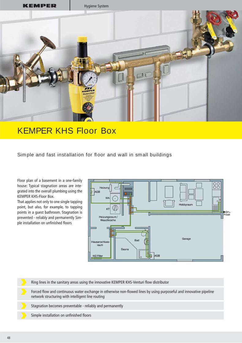
KEMPER KHS Floor Box
Simple and fast installation for fl oor and wall in small buildings
Ring lines in the sanitary areas using the innovative KEMPER KHS-Venturi fl ow distributor
Forced fl ow and continuous water exchange in otherwise non-fl owed lines by using purposeful and innovative pipeline network structuring with intelligent line routing
Stagnation becomes preventable - reliably and permanently
Simple installation on unfi nished fl oors
Floor plan of a basement in a one-family house: Typical stagnation areas are inte-grated into the overall plumbing using the KEMPER KHS-Floor Box. That applies not only to one single tapping point, but also, for example, to tapping points in a guest bathroom. Stagnation is prevented - reliably and permanently Sim-ple installation on unfi nished fl oors

High quality is our standard · since 1864 49
Hygiene System
The supply lines to seldom-used outdoor tapping points (e.g., KEMPER ’Frosti®’) can be constantly fl owed by using innovative pipeline conduction combined with the KEMPER KHS Floor Box.
That results in permanent, hygienically safe drinking water at the tapping point even after long winter periods. The KEMPER KHS Floor Box facilitates fast and reliable installation on the un-fi nished fl oor. The KEMPER KHS Floor Box (Figure 640 50) is available in the nominal widths DN 15 and DN 20 or in combina-tion with the frost-proof outdoor valve ’Frosti®-plus’ as KEMPER Frosti Hygiene Set (Figure 640 60).
KEMPER KHS Floor Box Figure 640 50
The KEMPER KHS Multi-Circ Distributor Unit -static- is the core element in the KHS Floor Box. It can be used in the fl ooring structure or at any point in the building plumbing on the surface or concealed. The robust Neopor® insulating shell protects the component from corrosion and mechanical infl uences.
Water must fl ow!“Water is a friendly element for those who are familiar with it and know how to handle it.” Johann Wolfgang von Goethe (1749 - 1832)

50
KHS Mini Control System
Application MASTER/SLAVE technology
for small and medium size projects
The KEMPER KHS Mini Control System can run small and medium sized buildings such as schools, kindergartens, small plants, in-dustry, department stores, holiday homes, etc.
MASTER/SLAVE technologyThe basic version includes the MASTER con-trol as the smallest solution for performingfl ushing measures in the domestic watersystem, with triggering for the fl ush valve,and signal evaluation.By using the integrated CAN BUS technolo-gy in the MASTER, up to 31 SLAVE controls can be triggered directly by the MASTER control with a graphic display. That means in buildings up to 32 KHS fl ush groups (fl ush valve, temperature and volume fl ow sensor, overfl ow monitoring) can be con-nected using the MASTER-SLAVE technol-ogy. The MASTER-SLAVE fl ush groups can be manually confi gured on the MASTER or through confi guration software with a customer provided PC via an optional USB interface cable.
Intelligent fl ushing in small and medium size buildings
Three fl ushing modes: Time, temperature or volume
Documentation of the fl ushing process in a “Flushing log”
Easy to operate MASTER-SLAVE system
Advantages at a glance
KEMPER KHS Mini Control System

High quality is our standard · since 1864 51
Hygiene System
Secure registration of a leak by using a water sensor with immediate drinking water system shutoff
Space-saving, easily retrofi t package for all types of buildings in inventory as well as new buildings
Maximum fl ow isolating ball without concussion through slow closing / opening according to EN 13828
Timer programming facilitates automatic security when leaving the building or during long absences
Acoustic and visual alarm to the leak controller reports a leak
The alarm can be forwarded to a building control system (BMS)
KHS-VAV-plus or KHS-VAV with/without spring-reset servodrive Water sensor with up to 3 possible monitored lines KEMPER Leak Controller with integrated timer Location: Drinking water building connection room or roof units with DW heating
Advantages at a glance
Building drinkingwater
CDHWC
Control
KEMPER Leak Security System
Small cause - large effect!
Undetected leaks are the reason for costly reconstruction work in buildings after water damage. If there is a leak due to a burst pipe, weak points in the connection or in the drinking water sys-tem plant engineering, water often fl ows undetected for hours or even days in highly sensitive building sections.

52
Dendrit CAD
KEMPER Dendrit CAD
Planning reliability in ACAD®, Bricscad® or independent in Classic
Planning building-engineering plants with the greatest planning reliability is guaranteed by the innovative KEM-PER Dendrit CAD software.
Naturally, it includes consistent and uni-form menu guidance. The drawing can be downloaded in the CAD as *.dxf or *.dwg formats.
Processing the downloaded fl oor plan and the entire hydraulic calculation in CAD is problem-free with the familiar Dendrit desktop. Branch plans are automatically generated in the CAD and Classic by the plan generator. The unlimited drawing area in the CAD means full use of the hydrau-lics limits in Dendrit. That makes hydraulic calculation possible in up to 99 fl oors or in 99 branch lines.
With the plan generator, approx. 80% of the drawing work is saved even with differ-
ent fl oors or room uses. That naturally also applies to all pipe network calculations in the sanitary, heating and gas work.
KEMPER Dendrit CAD provides the unique tool, easy to use simulation tool as an add-on to standard-compliant calculation.
There, not only the temperature history for the entire fl ow path is checked and opti-mised but the exact selection and settings for the valves and the pump is also under-taken. That is accomplished in cooperation with the companies Grundfox and Wilo.
The KEMPER KHS Hygiene System for preventing stagnation and temperature overshooting in the cold drinking water sector and now also in warm drink-ing water is likewise implemented as a simulation tool. The KEMPER Dendrit CAD software is being technically accompanied by the Münster University of Applied Sci-
ences and Prof. Bernd Rickmann. The soft-ware can be procured comprehensively for drinking water, wastewater, heating and gas pipeline calculations.
DendritDendrit

High quality is our standard · since 1864 53
Dendrit CAD
Planning reliability through calculation and simulation
Advantages at a glance
KEMPER Simulation Tool for optimising
circulation simulation incl. pump selection from the lines from the companies Grundfos and Wilo
KHS-Simulation for optimisation and calculation of the water exchange
Drawing support
plan generator optionally in CAD or Classic
Operating systems
Windows 2000 / Windows XP / Windows Vista / Windows 7
Pipeline calculations
Drinking water calculations acc DIN 1988 including circulation calculation DVGW W 553, circulation simulation for optimising the temperature curve, valve and pump selection
Waste water calculation acc DIN EN 12056
Heater pipeline calculation Gas pipeline calculation acc TRGI
Building engineering
Heating load calculation acc DIN EN 12831
Radiator design and fl oor heating calculation
Cooling load calculation acc the computer model in VDI 2078
Unlimited drawing area
Download fl oor plan and process in the familiar Dendrit desktop
Innovative simulation program for the KEMPER drinking water circulation and the KEMPER KHS Hygiene System facilitate the greatest planning and operational reliability
Training, support and updates are free of charge – no annual maintenance costs!
54
Stop-valve water meter range
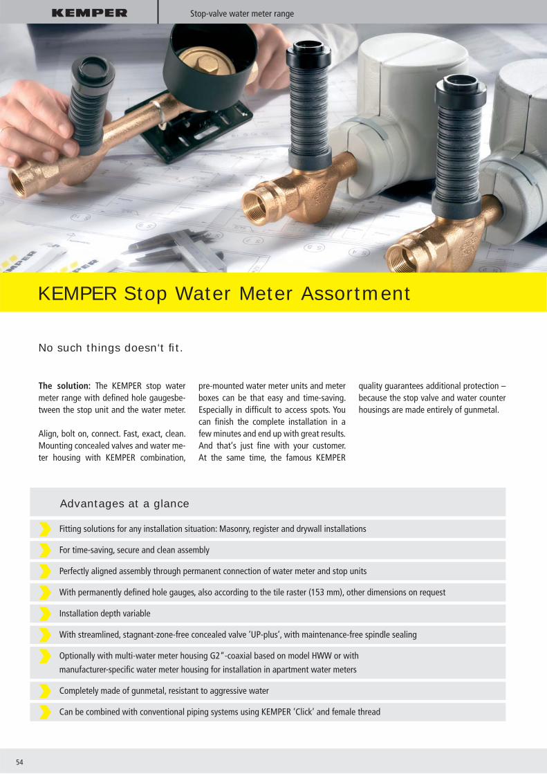
KEMPER Stop Water Meter Assortment
No such things doesn‘t fi t.
The solution: The KEMPER stop water meter range with defi ned hole gaugesbe-tween the stop unit and the water meter.
Align, bolt on, connect. Fast, exact, clean. Mounting concealed valves and water me-ter housing with KEMPER combination,
pre-mounted water meter units and meter boxes can be that easy and time-saving. Especially in diffi cult to access spots. You can fi nish the complete installation in a few minutes and end up with great results.And that‘s just fi ne with your customer.At the same time, the famous KEMPER
quality guarantees additional protection – because the stop valve and water counter housings are made entirely of gunmetal.
Fitting solutions for any installation situation: Masonry, register and drywall installations
For time-saving, secure and clean assembly
Perfectly aligned assembly through permanent connection of water meter and stop units
With permanently defi ned hole gauges, also according to the tile raster (153 mm), other dimensions on request
Installation depth variable
With streamlined, stagnant-zone-free concealed valve ’UP-plus’, with maintenance-free spindle sealing
Optionally with multi-water meter housing G2“-coaxial based on model HWW or with
manufacturer-specifi c water meter housing for installation in apartment water meters
Completely made of gunmetal, resistant to aggressive water
Can be combined with conventional piping systems using KEMPER ’Click’ and female thread
Advantages at a glance
High quality is our standard · since 1864 55
Multi-water meter housing G2“-coaxial
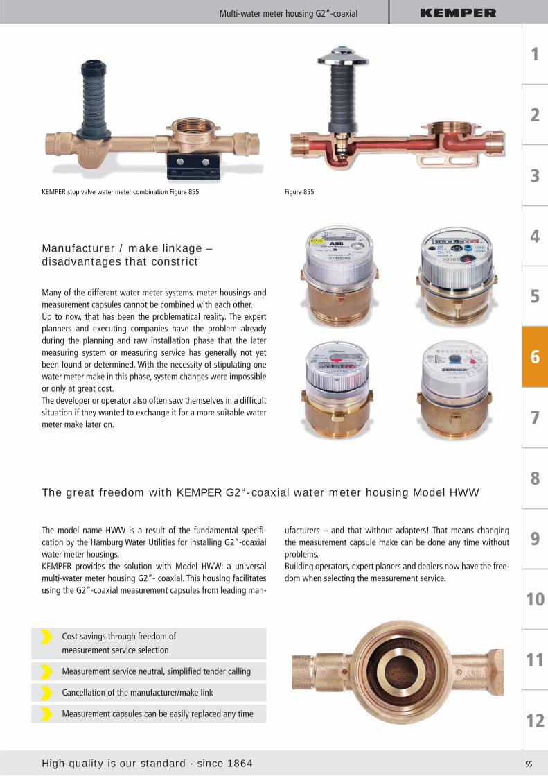
KEMPER stop valve water meter combination Figure 855 Figure 855
Manufacturer / make linkage –disadvantages that constrict
Many of the different water meter systems, meter housings and measurement capsules cannot be combined with each other. Up to now, that has been the problematical reality. The expert planners and executing companies have the problem already during the planning and raw installation phase that the later measuring system or measuring service has generally not yet been found or determined. With the necessity of stipulating one water meter make in this phase, system changes were impossible or only at great cost. The developer or operator also often saw themselves in a diffi cult situation if they wanted to exchange it for a more suitable water meter make later on.
The great freedom with KEMPER G2“-coaxial water meter housing Model HWW
The model name HWW is a result of the fundamental specifi -cation by the Hamburg Water Utilities for installing G2“-coaxial water meter housings.KEMPER provides the solution with Model HWW: a universal multi-water meter housing G2“- coaxial. This housing facilitates using the G2“-coaxial measurement capsules from leading man-
ufacturers – and that without adapters! That means changing the measurement capsule make can be done any time without problems.Building operators, expert planers and dealers now have the free-dom when selecting the measurement service.
Cost savings through freedom of
measurement service selection
Measurement service neutral, simplifi ed tender calling
Cancellation of the manufacturer/make link
Measurement capsules can be easily replaced any time

56
Stop-valve water meter combination
KEMPER stop water-metercombinationThe economical, space-saving route for any installation
Fits even in narrow spaces,
e.g. when renovating
Flexible through versatile installation lengths and hole
Gauges 153 mm according to tile raster, 130 mm, 90 mm
(with activation cap for concealed inspection fl ap installa-
tion), other dimensions on request
For single cold or warm measurements
Universal for masonry, shaft, register and pre-wall
Assembly with versatile fastening facilities for register
and prewall through optional mounting foot
With insulating shell as accessory,
Building Material Class B1
KEMPER stop water-metercombination’DUO-plus’The inexpensive, compact dual route for cold and warm water metering
Universal for masonry, shaft, register and
prewall mounting
Completely mounted with DUO-attachment foot for
register, installation rails and wall mounting
Hole gauge 153 mm according to tile raster
With two integrated insulating shells,
Building Material Class B1
Figure 855
Figure 867

High quality is our standard · since 1864 57
Stop water meter box and pre-mounted water meter unit
KEMPER stop WCt box ’DUO’The clean solution behind the wall for register and prewall mounting in dry walls
Fits any prewall system with its versatile fastening
facilities and comprehensive accessories
Flexible in design through various KEMPER covers
Can be combined with standard inspection and covering
systems, Suitable for wireless layouts
Space saving through small dimensions of the galvanized
installation box (200 x 200 x 125 mm)
With insulating shell as accessory,
Building Material Class B1
KEMPER stop pre-mounted water meter units ’MONO’ and ’DUO’The rapid and safe blocks: Align, bolt on, connect - fi nished!
For time-saving, clean mounting, can be immediately tiled
Pre-mounted mounting angle makes it universally usable
for masonry, register and prewall mounting
Optimal alignment through integrated alignment aid
Simple to maintain tile raster dimensions through
153 mm hole gauge
Optimal heat insulation through 2-component PU-foam,
EnEV recommended values for heat losses are clearly
undercut
Optimal noise insulation, damp-proof,
Building Material Class B2
If desired, with F90 fi re-prevention jacketing
and test certifi cate
Pre-mounted unit ’MONO’ Figure 856 for individual measurements in basement, shaft and fl oor level
Pre-mounted unit ’DUO’ Figure 857 for fl oor level metering
Figure 870 07
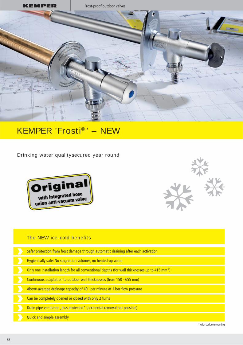
58
Frost-proof outdoor valves
KEMPER ’Frosti®’ – NEW
Drinking water qualitysecured year round
Safer protection from frost damage through automatic draining after each activation
Hygienically safe: No stagnation volumes, no heated-up water
Only one installation length for all conventional depths (for wall thicknesses up to 415 mm*)
Continuous adaptation to outdoor wall thicknesses (from 150 - 655 mm)
Above-average drainage capacity of 40 l per minute at 1 bar fl ow pressure
Can be completely opened or closed with only 2 turns
Drain pipe ventilator „loss protected“ (accidental removal not possible)
Quick and simple assembly
* with surface mounting
The NEW ice-cold benefi ts
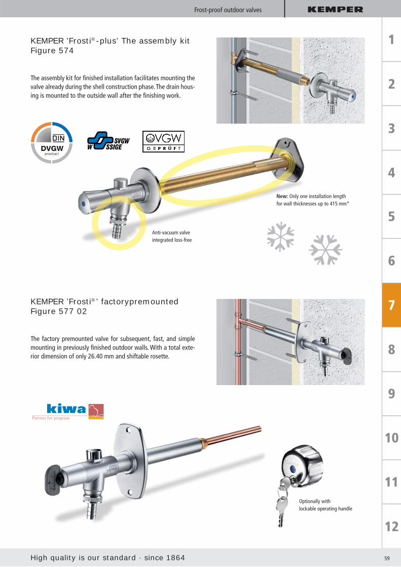
High quality is our standard · since 1864 59
Frost-proof outdoor valves
KEMPER ’Frosti®-plus’ The assembly kitFigure 574
The assembly kit for fi nished installation facilitates mounting the valve already during the shell construction phase. The drain hous-ing is mounted to the outside wall after the fi nishing work.
KEMPER ’Frosti®’ factorypremountedFigure 577 02
The factory premounted valve for subsequent, fast, and simple mounting in previously fi nished outdoor walls. With a total exte-rior dimension of only 26.40 mm and shiftable rosette.
Anti-vacuum valveintegrated loss-free
New: Only one installation length for wall thicknesses up to 415 mm*
Optionally withlockable operating handle

60
Central supply station for water and electricity
KEMPER ’Tresor’
Lockable built-in wall cupboard made of highgrade,brushed stainless steel no. 1.4404
With socket combinations 230 V / 400 V, Make Mennekes, protection class IP 44, equipment can be chosen as needed
With KEMPER frost proof outdoor valve with automatic drain function, with DVGW and noise protection permit
Comfortable water and electricity supply from a central point outdoors
Noble in design because made entirely out of high quality stainless no. 1.4404
Secure protection against unauthorised water and electricity tapping during use through
integrated fl ap forhose and cable connection
Secure plug lock can be converted to an existing lock system
With KEMPER frost-proof outdoorvalve: Guarantees frost-proofness
With socket combinations for 230 and 400 Volts, made by Mennekes, IP 44, hard wired, can be
supplied for D, A , CH, DK, F, GB; optionally with fault current protection in box
Safe cut-off of water and electric connections in accordance with VDE Directive for moist areas
and rooms VDE 0100 Part 737
Availableas modular system: Size and equipment freely selectable as needed

High quality is our standard · since 1864 61
Central supply station for water and electricity
KEMPER ’Mini-Tresor’ Figure 211 / 212
Technically mature and noble in design: KEMPER ’Tresor’, the compact supply station for the outdoor area, facilitates simul-taneous, comfortable water and electricity supply at one central point. Regardless of which application and which device, you can always fi nd the fi ttingsize and equipment.
KEMPER ‘Mini-Tresor‘ built-in wall cabinet Figure 211, H/W/D: 340x300x120 mm, the compact supply station for a single-family house
KEMPER ‘Mini-Tresor‘ surface mounted cabinet Figure 212,H/W/D: 315/280/132 mm
Safe andcomfortable in use
Safe for public buildings (schools, kindergarten, hotels,
fi re department buildings), events (markets, festivals)
camping sites, residential construction
Comfortable for various applications with electricity
and water, for the garden, patio, penthouse apartment
(lawnmower, electric grill)
KEMPER ‚Tresor’ Figure 210 / 213
The supply station with various connection facilities, e.g. water and electrical connection for 230 V / 400 V, can be expanded at construction site e.g. with gas, telephone, antenna or wastewater connection, for private and commercial applications.
KEMPER ‘Tresor‘ built-in wall cabi-net Figure 210,H/W/D: 470x250x120 mm, for fl ush mounting
KEMPER ‘Tresor‘ surface mounted wall cabinet Figure 213, H/W/D: 510x285x130 mm, for subsequent fast and clean installation in previously fi nished outdoor walls and when the wall thickness is insuffi cient for fl ush mounting
Installation situation
The compact supply unit KEMPER ‘Tresor’ can be easily integrated in the masonry or concrete walls. To guarantee frost-proofness, aresidual wall thickness of 180 mm is required.

62
KEMPER System Valves
System valves
System valves ’sanpress’ and ’profi press’
The advantages for the fi nisher are clear: KEMPER valves with ‘sanpress‘ and ‘profi press‘ piping systems are installed quickly, safely and inexpensively.
stop valves with permanent press-fi ttingswith SC-contour systems ‘sanpress‘ and‘profi press‘ Figure 190 30
Material and time savings by using integrated press-fi t connections
Guaranteed hydro-tested tight connection
Full warranty if installation guidelines are observed
Advantages at a glance

High quality is our standard · since 1864 63
System valves
KEMPER anti-pollution check-valve with permanent press fi tting with contour sealing system ‘mapress‘ stainless steeland ‘mapress‘ copper Figure 193 22
KEMPER ‘Multi-Therm‘ with permanent gunmetalpress fi tting with contour sealing system ‘mapress‘ stainless steel and ‘mapress‘ copper Figure 143 22
KEMPER stop valves with permanent press fi tting for copper piping system ‚Sanha‘ and stainless steel piping system ‚Niro-San‘ Figure 190 35
System valves ’mapress’ and ’Mepla’
KEMPER provides the fi tting system valves for the Geberit piping systems Mepla, Mapress stainless steel and Mapress copper with permanently integrated press fi ttings made out of gunmetal and stainless steel.
Consistent implementation of the system concept is carried out with only two valve types for the three piping systems.
System valves ’Sanha’
KEMPER SANHA® system valve- with uniform system
Because, for the SANHA® connection technology with copper pipes and the SANHA® stainless steel piping system NiroSan® the matching system valve is now available from KEMPER.
KEMPER maximum fl ow isolating ball with permanent press fi tting system Geberit ‘Mepla‘ Figure 385 40

64
KEMPER Stainless Steel Valves
Stainless steel valves
Now the large range with newconnection facilities: With univer-sally male/female threads or Geberit mapress direct press fi tting system
For premium demands in drinking water installations, KEMPER now offers a large selection of valves made entirely of stainless steel for stopping, securing and regulating for both surface and concealed mounting. In processed drinking water (such as fully demineralised water and softened water), stainless steel, with its excellent material properties, is also the safe alternative. Guaran-tied perfect protection against corrosion with aggressive water.
You can fi nd more information about the extensive gunmetal valve range in chapters 2-8.
Completely stainless steel, resistant against aggressive water
With self-lubricating EPDM lip seals that can be replaced under pressure as a maintenance-free spindle sealing
Stagnant-zone-free
DVGW and soundproofi ng certifi cate
Connection facility for all common pipe systems
KEMPER free-fl ow stop valve Figure 073
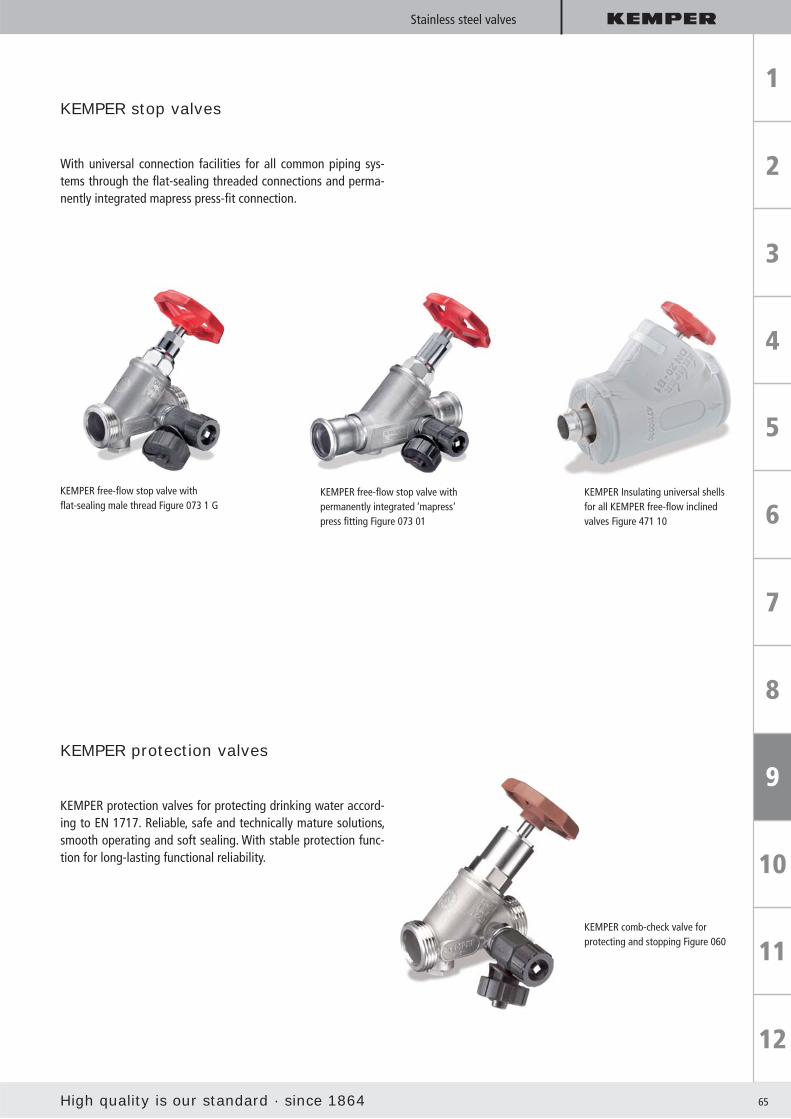
High quality is our standard · since 1864 65
Stainless steel valves
KEMPER stop valves
With universal connection facilities for all common piping sys-tems through the fl at-sealing threaded connections and perma-nently integrated mapress press-fi t connection.
KEMPER free-fl ow stop valve with fl at-sealing male thread Figure 073 1 G
KEMPER free-fl ow stop valve with permanently integrated ‘mapress‘ press fi tting Figure 073 01
KEMPER Insulating universal shells for all KEMPER free-fl ow inclined valves Figure 471 10
KEMPER protection valves
KEMPER protection valves for protecting drinking water accord-ing to EN 1717. Reliable, safe and technically mature solutions, smooth operating and soft sealing. With stable protection func-tion for long-lasting functional reliability.
KEMPER comb-check valve forprotecting and stopping Figure 060

66
Stainless steel valves
KEMPER regulating valves
KEMPER regulating valves reliably ensure the hydraulic compen-sation in complex sanitary installation systems. Made completely of stainless steel, in a multitude of function variants:
Can be pre-adjusted andstopped Manual / static or automatic /
thermal regulation
KEMPER ’Multi-Therm’automatic /thermalcirculation regulating valve Figure 041
KEMPER throttlevalve manual / static circulation regulation valve
Can be stopped without changing the presets With stop and drain for maintenance work with position display through adjustable bracket
KEMPER throttle-valve with preset Figure 078
KEMPER antipollution checkvalves(RV and KRV)
KEMPER check valve RV for protecting withfl ow optimised housing Figure 062
As combination check valve (KRV)
As fl ow check valve (KRV)
With test appliance for the prescribed function
test of the check valve
Completely stainless steel,
resistant against aggressive water
With self-lubricating EPDM lip seals that can be replaced
under pressure as a maintenance-free spindle sealing
Stagnant-zone-free
DVGW-, SVGW-, KIWA- and soundproofi ng certifi cate
Connection facility for all common piping systems
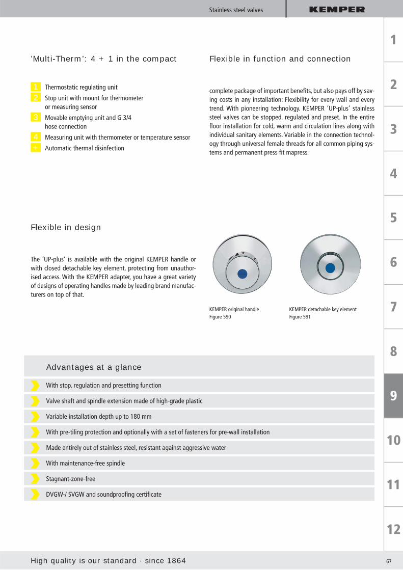
High quality is our standard · since 1864 67
Stainless steel valves
1 Thermostatic regulating unit
2 Stop unit with mount for thermometer or measuring sensor
3 Movable emptying unit and G 3/4 hose connection
4 Measuring unit with thermometer or temperature sensor
+ Automatic thermal disinfection
’Multi-Therm’: 4 + 1 in the compact Flexible in function and connection
complete package of important benefi ts, but also pays off by sav-ing costs in any installation: Flexibility for every wall and every trend. With pioneering technology. KEMPER ’UP-plus’ stainless steel valves can be stopped, regulated and preset. In the entire fl oor installation for cold, warm and circulation lines along with individual sanitary elements. Variable in the connection technol-ogy through universal female threads for all common piping sys-tems and permanent press fi t mapress.
Flexible in design
The ’UP-plus’ is available with the original KEMPER handle or with closed detachable key element, protecting from unauthor-ised access. With the KEMPER adapter, you have a great variety of designs of operating handles made by leading brand manufac-turers on top of that.
KEMPER original handle Figure 590
KEMPER detachable key elementFigure 591
With stop, regulation and presetting function
Valve shaft and spindle extension made of high-grade plastic
Variable installation depth up to 180 mm
With pre-tiling protection and optionally with a set of fasteners for pre-wall installation
Made entirely out of stainless steel, resistant against aggressive water
With maintenance-free spindle
Stagnant-zone-free
DVGW-/ SVGW and soundproofi ng certifi cate
Advantages at a glance

68
Shipbuilding
KEMPER valves for shipbuilding
Drinking water is a valuable and limited resource
That means it is exactly at high sea that drinking water hygiene needs to be complied with. Through a professional installation of the drinking water plant and the hydraulic compensation in the warm water system.
It is exactly here that the KEMPER hygiene system KHS starts. By using automatic circulation regulating valves with the corresponding monitoring and logging facilities in the warm water area.
And the use of fl ow distributors in the cold water area to prevent stagnation in seldom-used line sections. KEMPER Multi-Therm Figure 140
Individual components in KEMPER Hygiene System KHS
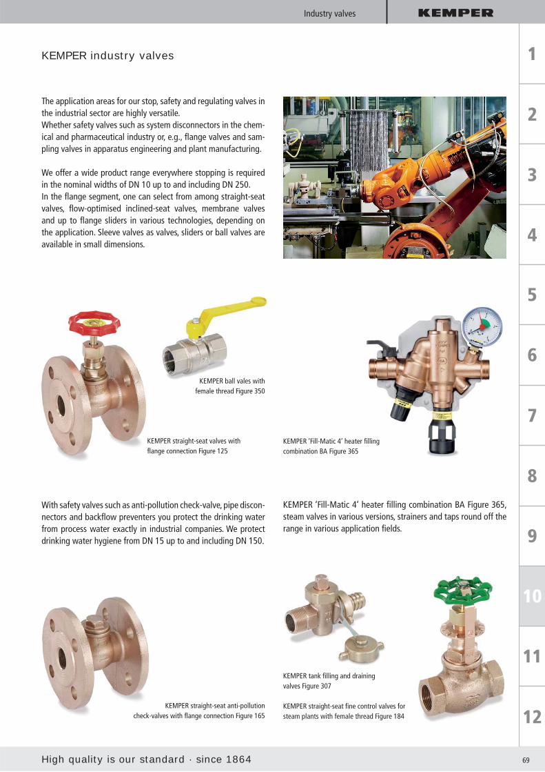
High quality is our standard · since 1864 69
Industry valves
KEMPER ball vales with female thread Figure 350
KEMPER tank fi lling and draining valves Figure 307
KEMPER straight-seat fi ne control valves for steam plants with female thread Figure 184
KEMPER straight-seat anti-pollution check-valves with fl ange connection Figure 165
KEMPER industry valves
The application areas for our stop, safety and regulating valves in the industrial sector are highly versatile.Whether safety valves such as system disconnectors in the chem-ical and pharmaceutical industry or, e.g., fl ange valves and sam-pling valves in apparatus engineering and plant manufacturing.
We offer a wide product range everywhere stopping is required in the nominal widths of DN 10 up to and including DN 250.In the fl ange segment, one can select from among straight-seat valves, fl ow-optimised inclined-seat valves, membrane valves and up to fl ange sliders in various technologies, depending on the application. Sleeve valves as valves, sliders or ball valves are available in small dimensions.
KEMPER ‘Fill-Matic 4‘ heater fi lling combination BA Figure 365, steam valves in various versions, strainers and taps round off the range in various application fi elds.
With safety valves such as anti-pollution check-valve, pipe discon-nectors and backfl ow preventers you protect the drinking water from process water exactly in industrial companies. We protect drinking water hygiene from DN 15 up to and including DN 150.
KEMPER ‘Fill-Matic 4‘ heater fi lling combination BA Figure 365
KEMPER straight-seat valves with fl ange connection Figure 125

70
Insulating shells
KEMPER insulating shells
Highest goal: Energy savings by insulating all valves
Insulation of pipelines and valves is prescribed by the legislator.
It is intended to reduce the global warming caused by humans and to attain sustainable handling of primary energy resources. These standards places requirements on heating, room air and warm water preparation plants. Furthermore, for cold-water con-ducting lines, insulation measures against condensation forma-tion, frost and heating from outdoors are to be taken into con-sideration.
With insulating shells from KEMPER, you comply with the strictest requirements!
Energy savings with KEMPER insulating shells
With KEMPER insulating shells you will achieve a noticeable re-duction in the primary energy demand of buildings. An economic benefi t for you, a relief for the environment.
Note: Planning insulating shells across the board avoids subsequent insulation work.
To prevent subsequent and expensive insulation measures, it is best to include a suitable insulating shell for each valve in the material list during the project and tender phase.
KEMPER insulating shells For rapid and economical insulation of KEMPER valves to prevent:
Energy / heat loss Condensate formation

High quality is our standard · since 1864 71
Insulating shells
Permanent closed or detachable:Everything is possible
KEMPER insulating shells - easy and safe closing
close fasten ready!
KEMPER insulating shells
are diffusion resistant to bonding with common adhesives
can be securely locked with the supplied fastening clips
Made of PE material
Building material class B1
Temperature resistant up to 100 °C
Thermal conductivity = 0.035 W/mK
No condensation
Simple and quick assembly
Diffusion resistant to bonding with common adhesives
Can be securely locked with the supplied fastening clips
KEMPER universal insulating shells Figure 471 10 for all KEMPER free-fl ow inclined valves
Insulating shells Figure 471 11 spe-cifi cally for KEMPER ‚Multi-Therm‘ automatic circulation regulation valves
Insulating shells Figure 471 12 specifi cally for KEMPER ’Multi-Fix’ manual circulation regulation valves
Insulating shells Figure 471 16 specially made for KEMPER con-cealed water meter combinations
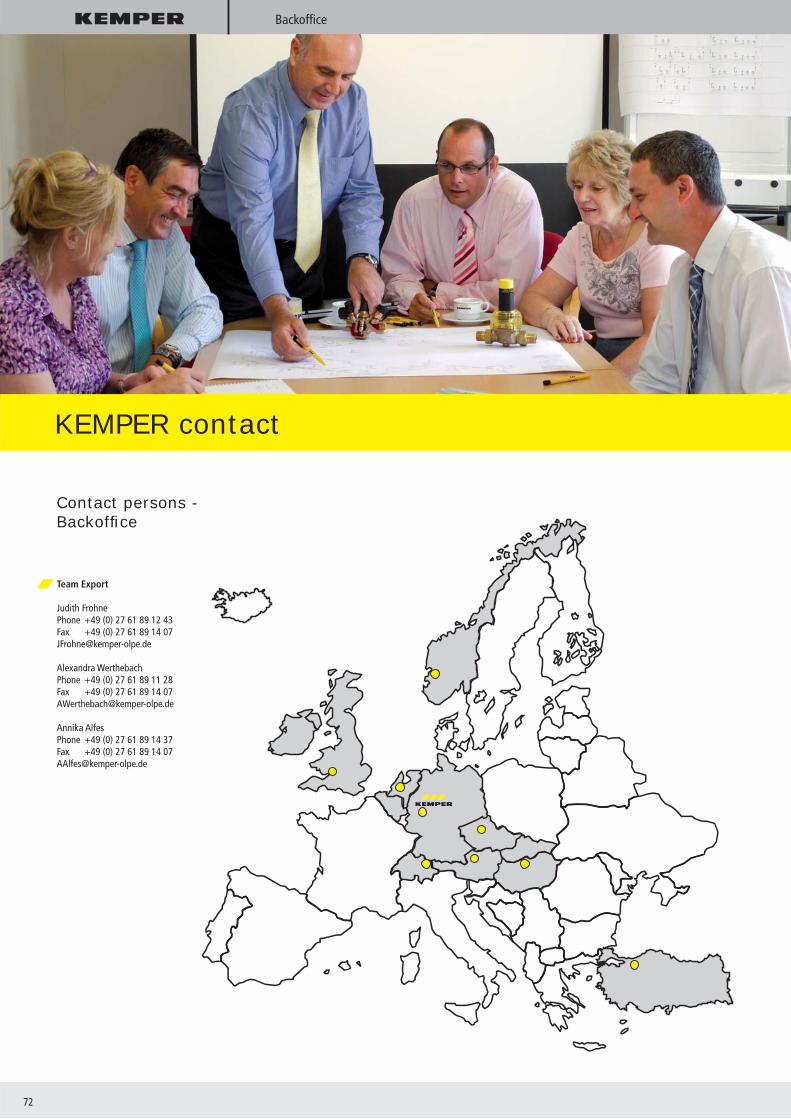
72
Backoffi ce
KEMPER contact
Contact persons - Backoffi ce
Team Export
Judith FrohnePhone +49 (0) 27 61 89 12 43Fax +49 (0) 27 61 89 14 [email protected]
Alexandra WerthebachPhone +49 (0) 27 61 89 11 28Fax +49 (0) 27 61 89 14 [email protected]
Annika AlfesPhone +49 (0) 27 61 89 14 37Fax +49 (0) 27 61 89 14 [email protected]
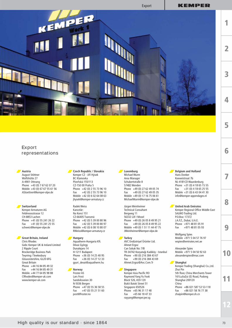
High quality is our standard · since 1864 73
Export
High quality is our standard · since 1864 73
Exportrepresentations
Austria August Stöttner Wolfshütte 27A-4901 OttnangPhone +43 (0) 7 67 62 07 20Mobile +43 (0) 67 67 55 61 [email protected]
SwitzerlandKemper Armaturen AGFeldmoosstrasse 12CH-8853 LachenPhone +41 (0) 55 241 26 22Fax +41 (0) 55 241 25 [email protected]
Great Britain, IrelandChris RhodesGebr. Kemper UK & Ireland Limited2 Ripple CourtBrockeridge Business ParkTwyning / Tewkesbury Gloucestershire, GL20 6FGGreat BritainPhone +44 16 84 85 49 32Fax +44 16 84 85 49 31 Mobile +44 77 64 85 98 [email protected]
Czech Republic / SlovakiaKemper CZ - Jiří HýsekBC KlamovkaPlzeňská 155/113CZ-150 00 Praha 5Phone +42 (0) 2 55 73 96 10Fax +42 (0) 2 55 73 96 10Mobile +42 (0) 6 02 64 08 [email protected]
Radek WeissKancelár:Na Konci 151CZ-66405 TvaroznáPhone +42 (0) 5 39 00 80 96Fax +42 (0) 5 39 00 80 97Mobile +42 (0) 6 08 10 80 [email protected]
HungaryAquatherm-Hungaria Kft.Dévai GyörgyDunalejaro 14H-1211 BudapestPhone +36 (0) 14 25 40 95Fax +36 (0) 14 27 12 [email protected]
NorwayFroster AS Lars FrostSandviksveien 30 N-5036 Bergen Phone +47 (0) 55 36 58 55 Fax +47 (0) 55 21 51 60 [email protected]
LuxemburgMichael WurmArea ManagerSchubertstraße 857482 WendenPhone +49 (0) 27 62 49 05 74Fax +49 (0) 27 62 49 05 35Mobile +49 (0) 17 16 75 06 [email protected]
Jürgen WeinheimerTechnical ConsultantBergweg 1156332 Löf / MoselPhone +49 (0) 26 05 8 49 95 21Fax +49 (0) 26 05 8 49 95 22Mobile +49 (0) 1 51 11 44 47 [email protected]
TurkeyAVC Endüstriyel Ürünler Ltd.Ahmet ErgozCan Sokak No: 7/B TR-34742 Kozyatagı Kadıköy - IstanbulPhone +90 (0) 216 384 43 67Fax +90 (0) 216 384 43 [email protected]
SingaporeKemper Asia Pacifi c RORaymond Yang Yu FookBlock 526, #20-120Bukit Batok Street 51Singapore 650526Phone +65 96 31 17 48Fax +65 66 18 47 [email protected]
Belgium and HollandHans DonkerKoeweistraat 7bNL-4181CD WaardenburgPhone +31 (0) 4 18 65 15 55Fax +31 (0) 4 18 65 25 55Mobile +31 (0) 6 43 04 41 [email protected]
United Arab EmiratesKemper Regional Offi ce Middle EastSALWO Trading Ltd.P.O.Box: 17372J.A.F.Z., Dubai, U.A.E.Phone +971 48 81 05 91Fax +971 48 81 05 93
Wolfgang SpiesMobile +971 5 04 57 76 [email protected]
Alexander SpiesMobile +971 5 04 50 92 [email protected]
ShanghaiKemper Trading (Shanghai) Co.,Ltd.Zhai Pin5th fl oor, China Merchants Tower161LuJiaZui (E) Road, PudongShanghai 200120ChinaPhone +86 021 587 53 53-118Fax +86 021 58 76 77 [email protected]

74
Notes

High quality is our standard · since 1864 75
Notes

Valves
KEM
P 70
00 0
1/11
w w w. ke m p e r- o l p e . d e High quality is our standard · since 1864
Gebr. Kemper GmbH + Co. KGMetallwerkeHarkortstraße 5 · D-57462 Olpe
Phone +49 27 61 - 8 91 - 0Fax +49 27 61 - 8 91 - 1 [email protected]