valves & regulators - exceltec inc. · pdf filevalves & regulators directional control...
TRANSCRIPT
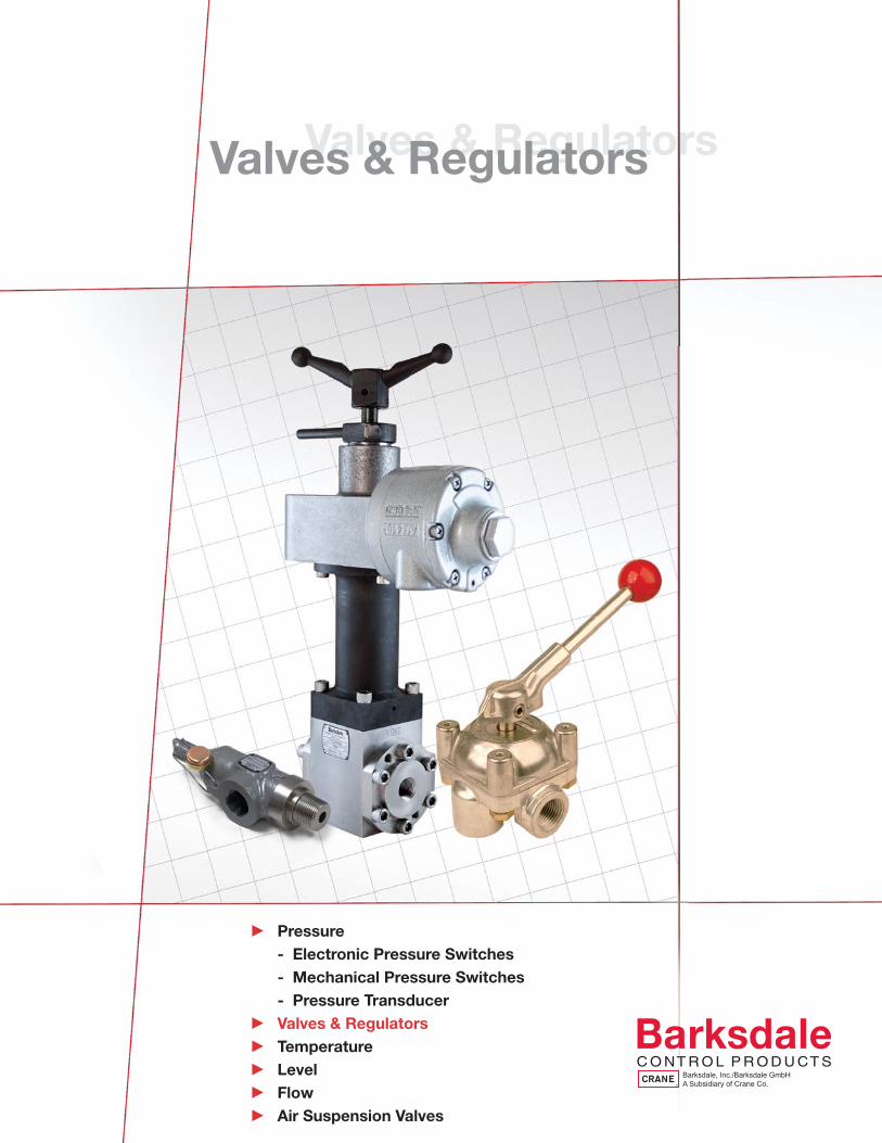
c Pressure - Electronic Pressure Switches - Mechanical Pressure Switches - Pressure Transducerc Valves & Regulatorsc Temperaturec Levelc Flowc Air Suspension Valves
Valves & RegulatorsValves & Regulators

Valves & Regulators Directional Control Valve Products Supplemental Guide 3
Valves
Series 9000, 9020 - Shear-Seal® Directional Control Valve 7Series 9040, 9080 - Low Pressure OEM Valves 9Series 6140, 6180 - High Pressure OEM Valves 11Series 6900, 6940 - High Pressure OEM Manipulator Valves 13Series 140, 200, 920, 5620 - Heavy Duty Valves 15Series 3760 - Subplate Mounted Heavy Duty Valve 17Models A14 and H14 - Series II Valve 19Model 371MT7 - Explosion Proof Position Indicator 21Series 4140 - High Pressure Valve 23518, 526 Series - MicrotorqueTM Valve 25Series 422 Solenoid Valve - Shear-Seal® Directional Control 27
Regulators
Series 20313 - 1/2” Heavy Duty Hydraulic Regulator 29Series 20415 - 3/4” Hydraulic Regulator 31Series 20495 - 3/4” Heavy Duty Hydraulic Regulator 33Series 20517 - 1-½” Hydraulic Regulator 35Series 20597 - 1-½” Heavy Duty Hydraulic Regulator 37
Relief Valve
Series 8010 - Pressure Relief Valve 39Installation and Operating Instructions for Hydraulic Relief Valve 41
Table of Contents
Valves
1
Supplemental Guide Directional Control Valve Products
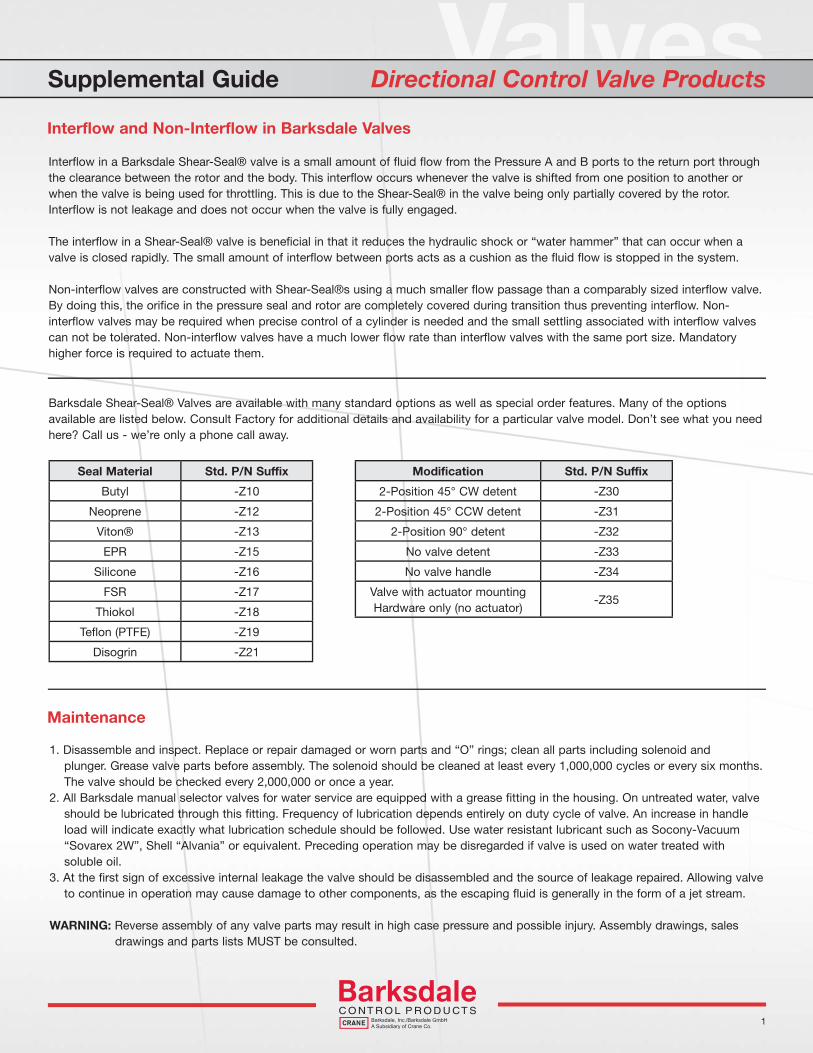
Interflow in a Barksdale Shear-Seal® valve is a small amount of fluid flow from the Pressure A and B ports to the return port through the clearance between the rotor and the body. This interflow occurs whenever the valve is shifted from one position to another or when the valve is being used for throttling. This is due to the Shear-Seal® in the valve being only partially covered by the rotor. Interflow is not leakage and does not occur when the valve is fully engaged.
The interflow in a Shear-Seal® valve is beneficial in that it reduces the hydraulic shock or “water hammer” that can occur when a valve is closed rapidly. The small amount of interflow between ports acts as a cushion as the fluid flow is stopped in the system.
Non-interflow valves are constructed with Shear-Seal®s using a much smaller flow passage than a comparably sized interflow valve. By doing this, the orifice in the pressure seal and rotor are completely covered during transition thus preventing interflow. Non-interflow valves may be required when precise control of a cylinder is needed and the small settling associated with interflow valves can not be tolerated. Non-interflow valves have a much lower flow rate than interflow valves with the same port size. Mandatory higher force is required to actuate them.
Interflow and Non-Interflow in Barksdale Valves
Seal Material Std. P/N Suffix
Butyl -Z10
Neoprene -Z12
Viton® -Z13
EPR -Z15
Silicone -Z16
FSR -Z17
Thiokol -Z18
Teflon (PTFE) -Z19
Disogrin -Z21
Modification Std. P/N Suffix
2-Position 45° CW detent -Z30
2-Position 45° CCW detent -Z31
2-Position 90° detent -Z32
No valve detent -Z33
No valve handle -Z34
Valve with actuator mountingHardware only (no actuator)
-Z35
Barksdale Shear-Seal® Valves are available with many standard options as well as special order features. Many of the options available are listed below. Consult Factory for additional details and availability for a particular valve model. Don’t see what you need here? Call us - we’re only a phone call away.
Maintenance
1. Disassemble and inspect. Replace or repair damaged or worn parts and “O” rings; clean all parts including solenoid and plunger. Grease valve parts before assembly. The solenoid should be cleaned at least every 1,000,000 cycles or every six months. The valve should be checked every 2,000,000 or once a year.2. All Barksdale manual selector valves for water service are equipped with a grease fitting in the housing. On untreated water, valve should be lubricated through this fitting. Frequency of lubrication depends entirely on duty cycle of valve. An increase in handle load will indicate exactly what lubrication schedule should be followed. Use water resistant lubricant such as Socony-Vacuum “Sovarex 2W”, Shell “Alvania” or equivalent. Preceding operation may be disregarded if valve is used on water treated with soluble oil. 3. At the first sign of excessive internal leakage the valve should be disassembled and the source of leakage repaired. Allowing valve to continue in operation may cause damage to other components, as the escaping fluid is generally in the form of a jet stream.
WARNING: Reverse assembly of any valve parts may result in high case pressure and possible injury. Assembly drawings, sales drawings and parts lists MUST be consulted.

2
Pressure Drop Curves
Supplemental Guide Directional Control Valve Products
Barksdale’s Shear-Seal® Valves have a much lower pressure drop than other valve technologies. This is possibly due to smooth internal passages and transitions within the valves which keep turbulent fl uid fl ow to a minimum. This translates to less heat build-up and higher pressures available to perform the required work.
0
10
20
30
40
50
60
70
80
90
100
110
120
130
140
150
5 10 15 20 25 30 35 40 45 50 55 60 65 70 75 80 85 90 95 100
PR
ES
SU
RE
DR
OP
(PS
I)
RATE OF FLOW (G.P.M.) - HYD. OIL OR WATER
1-1/4
1-1/8
1
7/8
3/4
5/8
23/32
9/16
17/321/2
7/163/85/16
9/327/32
1/4
3/16
(Theoretical)
Pressure Drop
1. Determine the Rate of Flow in G.P.M. or L.P.M. for fl uid being controlled.2. Determine minimum fl ow passage for valve from vale data sheet or sales drawing.3. Locate the Pressure Drop Curve from the chart above for the appropriate minimum fl ow passage (indicated by the small circles at each curve).4. Read the Pressure Drop from the vertical axis at the point where the fl ow rate (horizontal axis) intersectsthe appropriate pressure drop curve.
Note: The Pressure Drop is about the same in all fl ow directions.
Determine Pressure Drop for Barksdale Shear-Seal Valves
Valves
3
Supplemental Guide Directional Control Valve Products
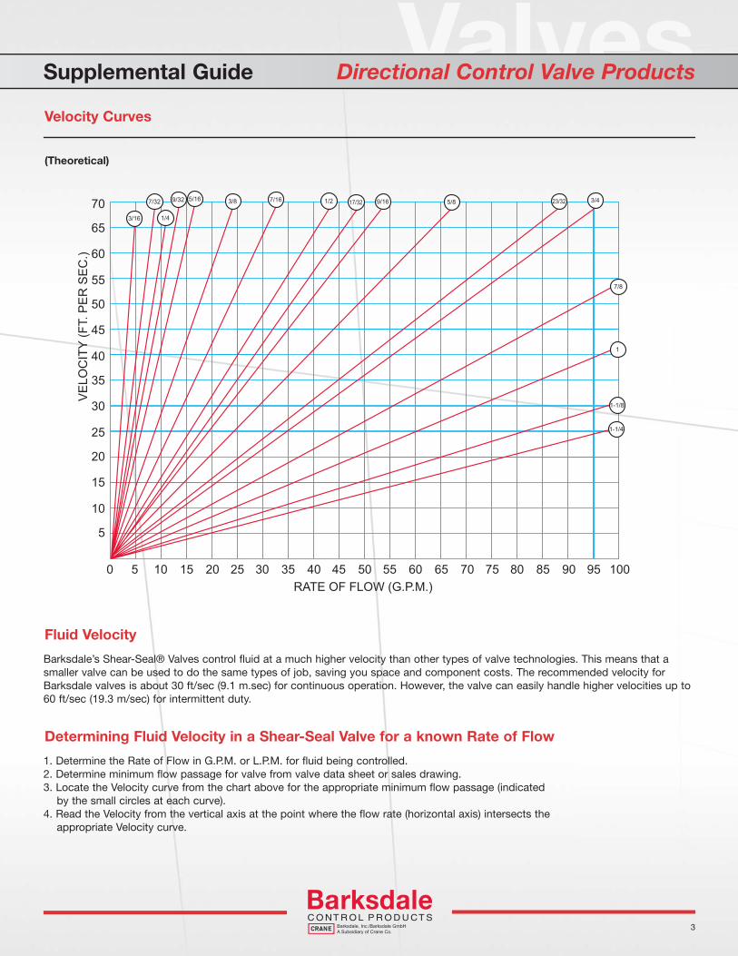
Velocity Curves
0
5
10
15
20
25
30
35
40
45
50
55
60
65
70
5 10 15 20 25 30 35 40 45 50 55 60 65 70 75 80 85 90 95 100
VE
LOC
ITY
(FT.
PE
R S
EC
.)
RATE OF FLOW (G.P.M.)
1-1/4
1-1/8
1
7/8
3/45/8 23/329/1617/321/27/163/85/169/327/32
1/43/16
(Theoretical)
Barksdale’s Shear-Seal® Valves control fl uid at a much higher velocity than other types of valve technologies. This means that a smaller valve can be used to do the same types of job, saving you space and component costs. The recommended velocity for Barksdale valves is about 30 ft/sec (9.1 m.sec) for continuous operation. However, the valve can easily handle higher velocities up to 60 ft/sec (19.3 m/sec) for intermittent duty.
Fluid Velocity
1. Determine the Rate of Flow in G.P.M. or L.P.M. for fl uid being controlled.2. Determine minimum fl ow passage for valve from valve data sheet or sales drawing.3. Locate the Velocity curve from the chart above for the appropriate minimum fl ow passage (indicated by the small circles at each curve).4. Read the Velocity from the vertical axis at the point where the fl ow rate (horizontal axis) intersects the appropriate Velocity curve.
Determining Fluid Velocity in a Shear-Seal Valve for a known Rate of Flow
See Barksdale’s Standard Conditions of Sale • Specifications are subject to modification at any time • Bulletin #B0050-D • 03/08 • ©2008 • Printed in the U.S.A.4
3211 Fruitland Avenue • Los Angeles, CA 90058 • 800-835-1060 • Fax: 323-589-3463 • www.barksdale.com
Supplemental Guide Directional Control Valve Products
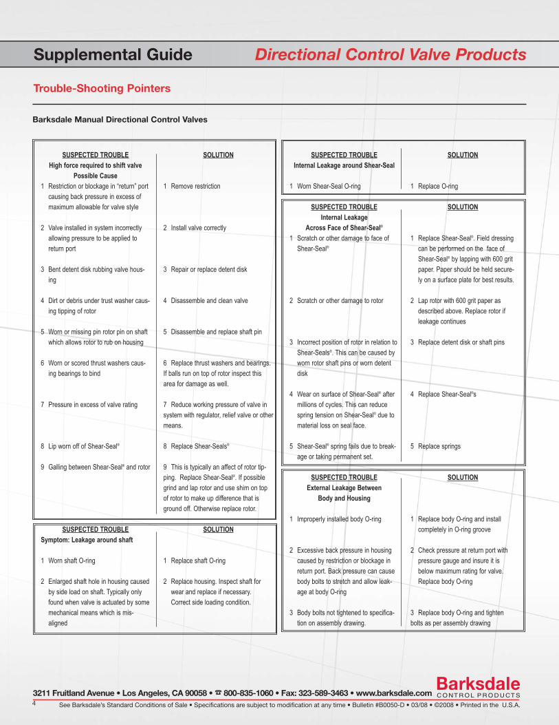
Trouble-Shooting Pointers
Barksdale Manual Directional Control Valves
SUSPECTED TROUBLEHigh force required to shift valve
Possible Cause1 Restriction or blockage in “return” port
causing back pressure in excess ofmaximum allowable for valve style
2 Valve installed in system incorrectlyallowing pressure to be applied toreturn port
3 Bent detent disk rubbing valve hous-ing
4 Dirt or debris under trust washer caus-ing tipping of rotor
5 Worn or missing pin rotor pin on shaftwhich allows rotor to rub on housing
6 Worn or scored thrust washers caus-ing bearings to bind
7 Pressure in excess of valve rating
8 Lip worn off of Shear-Seal®
9 Galling between Shear-Seal® and rotor
SUSPECTED TROUBLESymptom: Leakage around shaft
1 Worn shaft O-ring
2 Enlarged shaft hole in housing causedby side load on shaft. Typically onlyfound when valve is actuated by somemechanical means which is mis-aligned
SUSPECTED TROUBLEInternal Leakage around Shear-Seal
1 Worn Shear-Seal O-ring
SUSPECTED TROUBLEInternal Leakage
Across Face of Shear-Seal®
1 Scratch or other damage to face ofShear-Seal®
2 Scratch or other damage to rotor
3 Incorrect position of rotor in relation toShear-Seals®. This can be caused byworn rotor shaft pins or worn detentdisk
4 Wear on surface of Shear-Seal® aftermillions of cycles. This can reducespring tension on Shear-Seal® due tomaterial loss on seal face.
5 Shear-Seal® spring fails due to break-age or taking permanent set.
SUSPECTED TROUBLEExternal Leakage Between
Body and Housing
1 Improperly installed body O-ring
2 Excessive back pressure in housingcaused by restriction or blockage inreturn port. Back pressure can causebody bolts to stretch and allow leak-age at body O-ring
3 Body bolts not tightened to specifica-tion on assembly drawing.
SOLUTION
1 Remove restriction
2 Install valve correctly
3 Repair or replace detent disk
4 Disassemble and clean valve
5 Disassemble and replace shaft pin
6 Replace thrust washers and bearings.If balls run on top of rotor inspect thisarea for damage as well.
7 Reduce working pressure of valve insystem with regulator, relief valve or othermeans.
8 Replace Shear-Seals®
9 This is typically an affect of rotor tip-ping. Replace Shear-Seal®. If possiblegrind and lap rotor and use shim on topof rotor to make up difference that isground off. Otherwise replace rotor.
SOLUTION
1 Replace shaft O-ring
2 Replace housing. Inspect shaft forwear and replace if necessary.Correct side loading condition.
SOLUTION
1 Replace O-ring
SOLUTION
1 Replace Shear-Seal®. Field dressingcan be performed on the face ofShear-Seal® by lapping with 600 gritpaper. Paper should be held secure-ly on a surface plate for best results.
2 Lap rotor with 600 grit paper asdescribed above. Replace rotor ifleakage continues
3 Replace detent disk or shaft pins
4 Replace Shear-Seal®s
5 Replace springs
SOLUTION
1 Replace body O-ring and installcompletely in O-ring groove
2 Check pressure at return port withpressure gauge and insure it isbelow maximum rating for valve.Replace body O-ring
3 Replace body O-ring and tightenbolts as per assembly drawing

ValvesShear-Seal® Directional Control Valve Series 9000, 9020
General Specifications*
* See product confi gurator for additional options.
1
CLOSED CENTER (Float Center) OPEN CENTER CLOSED CENTER
T T T T T T
PortSizeNPT
Min.FlowPassageDia.
CvFactor
Air and OilRatedPressurepsi (bar)
ManipulatorRated Pressure psi (bar)
Approx.ShippingWeightlbs. (kg)
9000 SeriesNon Interfl ow
1/4” 3/16” 0.52 150 (10.3) 150 (10.3) 2 (0.9)
3/8” 3/16” 0.52 150 (10.3) 150 (10.3) 2 (0.9)
9020 SeriesInterfl ow
1/4” 3/8” 2.3 350 (24.1) 250 (17.2) 2 (0.9)
3/8” 3/8” 2.3 350 (24.1) 250 (17.2) 2 (0.9)
1/2” 3/8” 2.3 350 (24.1) 250 (17.2) 2 (0.9)
Working Pressure: Pneumatic or hydraulic from 150 psi to 350 psi (10.3 to 24.1 bar); see table
Cv, Minimum Orifice: See table
Back Pressure: Must not exceed 250 psi (17.2 bar) at return port for satisfactory operation
Proof Pressure: 1-1/2 times working pressure except at return port (without damage to valve)
Burst Pressure: 2-1/2 times working pressure except at return port (300 psi, 20.7 bar)
Media Temperature Range: -40° to +250°F (-40° to +121°C)
Wetted Material:Body:
Standard O-Rings:
Pressure Seals:
Rotor:
Anodized aluminum
Buna N
Brass
Hard anodized aluminum
Handle Rotation: 90°; 45° each side of center
Detent: 3-position detent (except -MC, -MR options)
Features Original Shear-Seal® technology Interflow/non interflow Easy panel mounting Tolerates contaminates Spring return option
Applications Pilot valve for pneumatic valve actuators Gas manifold controls Manual control of 2-position cylinder
Shown with option “D” red ball type handle

Shear-Seal® Directional Control Valve Series 9000, 9020Technical Drawings
See Barksdale’s Standard Conditions of Sale • Specifications are subject to modification at any time • Bulletin #B0040-H • 12/08 • ©2008 • Printed in the U.S.A. 2
3211 Fruitland Avenue • Los Angeles, CA 90058 • 800-835-1060 • Fax: 323-589-3463 • www.barksdale.com
Example: 902 2 -M
Product Configurator
Operation
-M Manual operation
-MC Manual (spring return to center)
-MR Manual (spring return to reverse)
Flow Pattern
Blank if closed center selector
-A Closed center manipulator
-G Open center manipulator
Options
-B 2-position 90° rotation (no center position)
-C Mounting bracket w/ 4 screws
-D Red ball type handle
-CD Mounting bracket & red ball type handle
-E Black knob (not available for spring return)
Series
900 Non interfl ow
902 Interfl ow
Port Size
1 1/4” pressure port
2 3/8” pressure port
3 1/2” pressure port (interfl ow only)
PORT SIZENPT
A B C
Black Knob
D
Regular
D-1
SpringCenter/Rever
D-2 E
Black Knob
F
Regular
F-1
SpringCenter/Rever
F-2
Black Knob
G
Regular
G-1
SpringCenter/Rever
G-2 H J
1/4 & 3/8 1.000(25.4)
2.625(66.7)
4.125(104.8)
3.656(92.9)
4.781(121.4)
5.188(133.8)
1.688(42.9)
2.062(52.4)
2.000(50.8)
2.406(61.1)
0.437(11.1)
0.437(11.1)
1.906(48.4)
0.531(13.5)
0.656(16.7)
1/2 1.000(25.4
3.125(79.4)
4.125(104.8)
3.718(94.4)
4.843(123.0)
5.250(133.4)
1.750(44.5)
2.125(54.0)
2.062(52.4)
2.468(62.7)
0.437(11.1)
0.437(11.1)
1.906(48.4)
0.625(15.9)
0.937(23.8)
C
2.781(70.6)
F2
D2
H E
G2 DIA.
PANEL MOUNTING SURFACE
PORT*
PORT*
5.437(138.1)
3.125(79.4)
SPRING CENTER/REVERSE
2.125(54.0)
2.375(60.3)
1.0 (25.4)
1.0 (25.4)
1.0 (25.4)
.562 (14.3)
2.0 (50.8)
.281 DIA.3 PLACES
MOUNTING BRACKET and 4 SCREWS
RED BALL TYPE HANDLE
#10-24NC-2 THD..375 MIN. FULL THD.FOR PANEL MTG.(TYP) 4 PLACES
PANEL MOUNTINGSURFACE .250 MAX.PANEL THICKNESSG1 DIA.
A
A
B
PORT*
1.250(31.8 )
PORT*
C
2.781(70.6)
D1
F1
EH
REGULAR
BLACK KNOB (not available with spring return)
2.375
.625
“-E” option
“-D” option “-C” option
Dimensions in inches (mm)
Optional O-ring Material
-Zxx See supplemental guide
Working Pressure: Gasses or hydraulic fl uids up to 500psi (34 bar)
Flow Capacity, Cv: See table
Back Pressure: Must not exceed 250 psi (17.2 bar) at return port for satisfactory operation
Pressure Drop: 14 psi (0.96 bar) at 20 ft/secSee Supplemental Guide for moredetailed information
Proof Pressure: 1-1/2 times working pressure except at return port
Burst Pressure: 2-1/2 times working pressure except at return port (500 psi [34 bar])
ValvesLow Pressure OEM Valves Series 9040, 9080
General Specifications*
* See product confi gurator for additional options.
1
Flow Capacity (Approx.)Service: Oil Approx.
ShippingWeight
lbs (kgs)Main Valve Port Size
20 ft/secgpm
(l/min)
40 ft/secgpm
(l/min)60 ft/sec
gpm (l/min)
Min. Flow Passage
Dia.Cv
Factor1/2" & 3/4" 14 (53) 28 (106) Use
HeavyDuty Valve
17/32" 4.80 3 (1.4)1" 25 (95) 51(190) 23/32" 9.20 10-1/2 (4.8)
1-1/2" 62 (235) 124 (471) 1-1/8" 24.0 20 (9.1)
Media Temperature Range:
-40° to +250°F (-40° to +121°C)
Wetted Material:Rotor:
Pressure Seals:
Shaft:
Body, Housing:
Bearings:
Standard O-rings:
Hard anodized aluminum
Brass
Stainless steel
Anodized aluminum
Tefl on/stainless steel
Buna N, others available
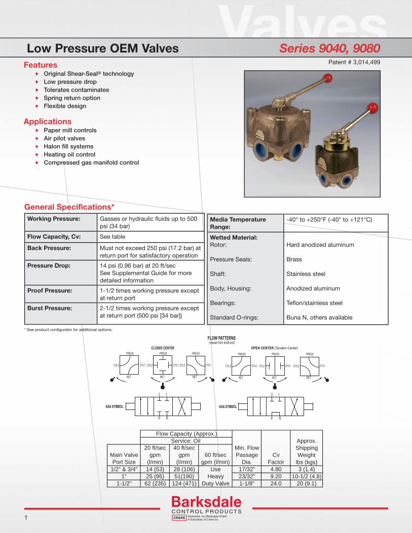
Features Original Shear-Seal® technology Low pressure drop Tolerates contaminates Spring return option Flexible design
Applications Paper mill controls Air pilot valves Halon fill systems Heating oil control Compressed gas manifold control
Patent # 3,014,499
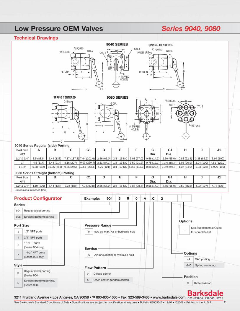
Low Pressure OEM Valves Series 9040, 9080Technical Drawings
See Barksdale’s Standard Conditions of Sale • Specifications are subject to modification at any time • Bulletin #B0055-B • 12/07 • ©2007 • Printed in the U.S.A. 23211 Fruitland Avenue • Los Angeles, CA 90058 • 800-835-1060 • Fax: 323-589-3463 • www.barksdale.com
Example: 904 5 R 0 A C 3
Product Configurator
Options
-See Supplemental Guide
for complete list
Flow Pattern
C Closed center
O Open center (tandem center)
Series
904 Regular (side) porting
908 Straight (bottom) porting
Port Size
3 1/2” NPT ports
4 3/4” NPT ports
51” NPT ports
(Series 904 only)
71-1/2” NPT ports
(Series 904 only)
Pressure Range
0 500 psi max. Air or hydraulic fl uid
Port Size A B C C1 D E F G G1 H J J1NPT Dia. Dia.
1/2" & 3/4" 3.5 (88.9) 5.44 (138) 7.37 (187.3) 7.94 (201.6) 2.56 (65.0) 3/8 - 16 NC 3.03 (77.0) 0.56 (14.2) 2.56 (65.0) 0.88 (22.4) 3.38 (85.9) 3.94 (100)1" 4.5 (114) 8.44 (214) 8.16 (207) 3.31 (84.1) 1/2 - 13 NC 3.59 (91.2) 0.75 (19.1) 1.06 (26.9) 3.94 (100)
1-1/2" 6.38 (162) 10.35 (263) 9.66 (245) 4.75 (121) 3/4 - 10 NC 0.88 (22.4) 1.37 (34.9)4.81 (122.2)5.906 (150)5.03 (128)
9080 Series Straight (bottom) Porting
9040 Series Regular (side) Porting
Port Size A B C C1 D E F G G1 H J J1NPT Dia. Dia.
1/2" & 3/4" 4.19 (106) 5.44 (138) 7.34 (186) 7.9 (200.8) 2.56 (65.0) 3/8 - 16 NC 3.88 (98.6) 0.56 (14.2) 2.56 (65.0) 2.50 (65.5) 4.22 (107) 4.78 (121)Dimensions in inches (mm)
9.03 (229.4)10.53 (267.5) 4.656 (118.3)
3.375 (85.7)3.375 (85.7)
Style
RRegular (side) porting,
(Series 904)
SStraight (bottom) porting,
(Series 908)
Service
A Air (pneumatic) or hydraulic fl uid
Position
3 Three position
Options
-A SAE porting
-MC Spring centering
9040 SERIES
9080 SERIES

ValvesHigh Pressure OEM Valves Series 6140, 6180
General Specifications*
* See product confi gurator for additional options.
1
Flow Capacity (Approx.)Service: Oil Approx.
Return PortBurst Rating
ShippingWeight
lbs (kgs)Main Valve Port Size
20 ft/secgpm
(l/min)
40 ft/secgpm
(l/min)
60 ft/secgpm
(l/min)
Min. Flow Passage
Dia.Cv
Factor1/4" & 3/8" 5 (19) 10 (38) Use
HeavyDutyValve
5/16" 1.56 1 1/2 (0.7)3,000 psi (207 bar)1/2" & 3/4" 14 (53) 28 (106) 17/32" 4.80 3 (1.4)
** "1 25 (95) 51(190) 23/32" 9.20 10 1/2 (4.6) 2,000 psi (138 bar)** "2/1-1
** 6140 Series Only
62 (235) 124 (471) 1-1/8" 24.0 20 (9.1) 1,500 psi (103 bar)
Working Pressure: Hydraulic fl uid up to 3000 psi (206bar)
Flow Capacity, Cv: See table
Back Pressure: Must not exceed 250 psi (17.2 Bar) at return port for satisfactory operation
Pressure Drop: 14 psi (0.96 bar) at 20 ft/secSee Supplemental Guide for moredetailed information
Proof Pressure: 1-1/2 times working pressure except at return port
Burst Pressure: 2-1/2 times working pressureexcept at return port (see fl ow chart)
Media Temperature Range:
-40° to +250°F (-40° to +121°C)
Wetted Material:Rotor:
Pressure Seals:
Shaft:
Body Housing:
Bearings:
Standard O-rings:
Back-up Rings:
Hard anodized aluminum
Brass
Stainless steel
Anodized aluminum
Carbon steel
Buna N, others available
Tefl on®
Features Original Shear-Seal® technology Low pressure drop Tolerates contaminates Spring return option Flexible design for OEM requirements
Applications Hydraulic presses Military equipment Paper mill controls Hydraulic pilot valves Railroad maintenance equipment Halon fill systems
Patent# 3,014,499
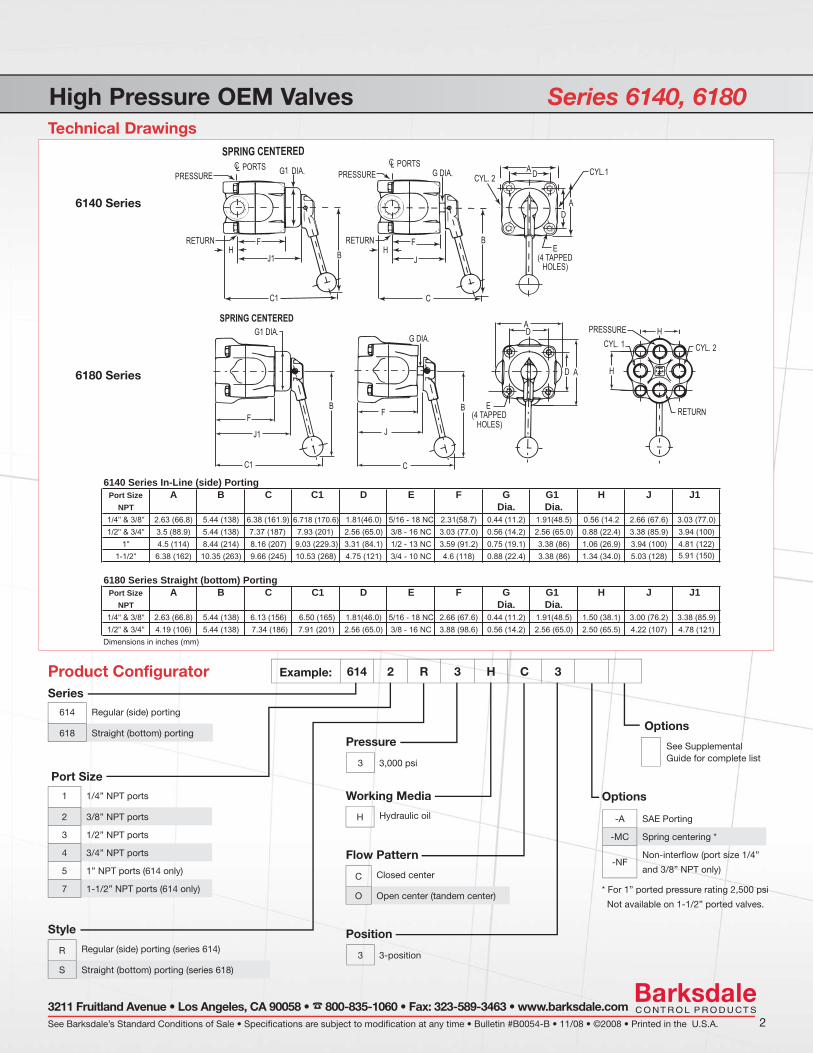
High Pressure OEM Valves Series 6140, 6180Technical Drawings
* For 1” ported pressure rating 2,500 psi
Not available on 1-1/2” ported valves.
See Barksdale’s Standard Conditions of Sale • Specifications are subject to modification at any time • Bulletin #B0054-B • 11/08 • ©2008 • Printed in the U.S.A. 23211 Fruitland Avenue • Los Angeles, CA 90058 • 800-835-1060 • Fax: 323-589-3463 • www.barksdale.com
Example: 614 2 R 3 H C 3
Product Configurator
Options
-A SAE Porting
-MC Spring centering *
-NFNon-interfl ow (port size 1/4”
and 3/8” NPT only)
Flow Pattern
C Closed center
O Open center (tandem center)
Port Size
1 1/4” NPT ports
2 3/8” NPT ports
3 1/2” NPT ports
4 3/4” NPT ports
5 1” NPT ports (614 only)
7 1-1/2” NPT ports (614 only)
6140 Series In-Line (side) PortingPort Size A B C C1 D E F G G1 H J J1
NPT Dia. Dia.1/4" & 3/8" 2.63 (66.8) 5.44 (138) 6.38 (161.9) 6.718 (170.6) 1.81(46.0) 5/16 - 18 NC 2.31(58.7) 0.44 (11.2) 1.91(48.5) 0.56 (14.2 2.66 (67.6) 3.03 (77.0)
1/2" & 3/4" 3.5 (88.9) 5.44 (138) 7.37 (187) 7.93 (201) 2.56 (65.0) 3/8 - 16 NC 3.03 (77.0) 0.56 (14.2) 2.56 (65.0) 0.88 (22.4) 3.38 (85.9) 3.94 (100)
1" 4.5 (114) 8.44 (214) 8.16 (207) 9.03 (229.3) 3.31 (84.1) 1/2 - 13 NC 3.59 (91.2) 0.75 (19.1) 3.38 (86) 1.06 (26.9) 3.94 (100) 4.81 (122)5.91 (150)1-1/2" 6.38 (162) 10.35 (263) 9.66 (245) 10.53 (268) 4.75 (121) 3/4 - 10 NC 4.6 (118) 0.88 (22.4) 3.38 (86) 1.34 (34.0) 5.03 (128)
6180 Series Straight (bottom) PortingPort Size A B C D E F G G1 H J J1
NPT Dia. Dia.1/4" & 3/8" 2.63 (66.8) 5.44 (138) 6.13 (156) 6.50 (165) 1.81(46.0) 5/16 - 18 NC 2.66 (67.6) 0.44 (11.2) 1.91(48.5) 1.50 (38.1) 3.00 (76.2) 3.38 (85.9)
1/2" & 3/4" 4.19 (106) 5.44 (138) 7.34 (186) 7.91 (201) 2.56 (65.0) 3/8 - 16 NC 3.88 (98.6) 0.56 (14.2) 2.56 (65.0) 2.50 (65.5) 4.22 (107) 4.78 (121)
Dimensions in inches (mm)
C1
Working Media
H Hydraulic oil
Position
3 3-position
Options
See Supplemental Guide for complete list
Series
Style
R Regular (side) porting (series 614)
S Straight (bottom) porting (series 618)
614 Regular (side) porting
618 Straight (bottom) portingPressure
3 3,000 psi
6140 Series
6180 Series

ValvesHigh Pressure OEM Manipulator Valves Series 6900, 6940
General Specifications*
* See product confi gurator for additional options.
1
Flow Capacity (Approx.)Service: Oil Approx.
ShippingWeight
lbs (kgs)Main Valve Port Size
20 ft/secgpm
(l/min)
40 ft/secgpm
(l/min)
60 ft/secgpm
(l/min)
Min. Flow Passage
Dia.Cv
Factor
1/4" & 3/8" 5 (19) 10 (38) UseHeavyDutyValve
5/16" 1.56 1 1/2 (0.7)
1/2" & 3/4" 14 (53) 28 (106) 17/32" 4.80 3 (1.4)
Working Pressure: Hydraulic fl uid up to 3000 psi (206bar)
Flow Capacity, Cv: See table
Back Pressure: Must not exceed 250 psi (17.2 Bar) at return port for satisfactory operation
Pressure Drop: 14 psi (0.96 bar) at 20 ft/secSee Supplemental Guide for moredetailed information
Proof Pressure: 1-1/2 times working pressure except at return port
Burst Pressure: 2-1/2 times working pressureexcept at return port (3000 psi [206 bar])
Media Temperature Range:
-40° to +250°F (-40° to +121°C)
Wetted Material:Rotor:
Pressure Seals:
Shaft:
Body Housing:
Bearings:
Standard O-rings:
Back-up Rings:
Hard anodized aluminum
Brass
Stainless steel
Anodized aluminum
Carbon steel
Buna N, others available
Tefl on®
Features Original Shear-Seal® technology Low pressure drop Tolerates contaminates Spring return option Special flow pattern for OEM designs
Applications Hydraulic presses Military equipment Paper mill controls Pipe forming Railroad maintenance equipment
Patent# 3,014,499

High Pressure OEM Manipulator Valves Series 6900, 6940Technical Drawings
See Barksdale’s Standard Conditions of Sale • Specifications are subject to modification at any time • Bulletin #B0057-A • 11/08 • ©2008 • Printed in the U.S.A. 23211 Fruitland Avenue • Los Angeles, CA 90058 • 800-835-1060 • Fax: 323-589-3463 • www.barksdale.com
Example: 690 2 R 3 H C 3
Product Configurator
Options
-A SAE Porting
-MC Spring centering
-NFNon-interfl ow (port size 1/4”
and 3/8” NPT only)
Flow Pattern
C Closed center manipulator (fl oat center)
O Open center (tandem center)
Port Size
1 1/4” NPT ports
2 3/8” NPT ports
3 1/2” NPT ports
4 3/4” NPT ports
6900 Series In-Line (side) PortingPort Size A B C C1 D E F G G1 H J J1
NPT Dia. Dia.1/4" & 3/8" 2.63 (66.8) 5.44 (138) 6.38 (161.9) 6.718 (170.6) 1.81(46.0) 5/16 - 18 NC 2.31(58.7) 0.44 (11.2) 1.91(48.5) 0.56 (14.2 2.66 (67.6) 3.03 (77.0)
1/2" & 3/4" 3.5 (88.9) 5.44 (138) 7.37 (187) 7.93 (201) 2.56 (65.0) 3/8 - 16 NC 3.03 (77.0) 0.56 (14.2) 2.56 (65.0) 0.88 (22.4) 3.38 (85.9) 3.94 (100)
6940 Series Straight (bottom) PortingPort Size A B C D E F G G1 H J J1
NPT Dia. Dia.1/4" & 3/8" 2.63 (66.8) 5.44 (138) 6.13 (156) 6.50 (165) 1.81(46.0) 5/16 - 18 NC 2.66 (67.6) 0.44 (11.2) 1.91(48.5) 1.50 (38.1) 3.00 (76.2) 3.38 (85.9)
1/2" & 3/4" 4.19 (106) 5.44 (138) 7.34 (186) 7.91 (201) 2.56 (65.0) 3/8 - 16 NC 3.88 (98.6) 0.56 (14.2) 2.56 (65.0) 2.50 (65.5) 4.22 (107) 4.78 (121)
Dimensions in inches (mm)
C1
Working Media
H Hydraulic oil
Position
3 3-position
Options
See Supplemental Guide for complete list
Series
Style
R Regular (side) porting (series 690)
S Straight (bottom) porting (series 694)
690Regular (side) porting, manipulator
fl ow pattern
694Straight (bottom) porting,
manipulator fl ow pattern
Pressure
3 3,000 psi
6900 Series
6940 Series

1
ValvesHeavy Duty Valves Series 140, 200, 920, 5620
Working Pressure: Air (pneumatic) up to 4,000 psi (276 bar) hydraulic oil or lubricated water up to 6,000 psi (413 bar)
Flow Capacity, Cv: See table
Back Pressure: Must not exceed 250 psi (17.2 bar) at return port for satisfactory operation
Pressure Drop: 14 psi (0.96 bar) at 20 ft/sec See Supplemental Guide for more detailed information
Proof Pressure: 1-1/2 times working pressure except at return port
Burst Pressure: 2-1/2 times working pressure except at return port (3,000 psi [206 bar])
Media Temperature Range:
-40° to +250°F (-40° to +121°C)
Rotor: 400 series stainless steel
Pressure Seals: Stainless steel
Shaft: Stainless steel
Body: Bronze
Housing: Ductile iron
Standard O-ring: Buna N, others available
Back-up Rings: Tefl on®
Flow Capacity (Approx.)
Service: Oil and Lubricated Water
Main Valve Port Size
20 ft/secgpm (l/min)
40 ft/secgpm (l/min)
60 ft/secgpm (l/min)
Min. Flow Passage Dia.
CvFactor
Approx. ShippingWeight lbs (kgs)
140/920SeriesValve
1/4” 3 (11) 6 (23) 9 (34) 1/4” 0.95 4.5 (2)
3/8” & 1/2” 9 (34) 19 (72) 28 (106) 7/16” 3.20 8.5 (3.9)
3/4” & 1” 25 (95) 50 (189) 75 (284) 23/32” 9.20 21.5 (9.8)
1-1/2” 57 (217) 114 (433) 171 (650) 1-3/32” 21.00 48.5 (22)
200/562SeriesValve
1/4” 3 (11) 6 (23) 9 (34) 1/4” 0.95 4.5 (2)
1/2” 5 (19) 10 (38) 15 (57) 5/16” 1.60 8.5 (3.9)
1” 9 (34) 19 (72) 28 (106) 7/16” 3.20 21.5 (9.8)
General Specifications*
Features Original Shear-Seal® technology High velocity flow Tolerates contaminates Low handle load at high pressures Spring return option Low pressure drop
Applications Land-based and offshore drilling equipment Steel mills Nitrogen charging panels Refineries and chemical processing plants Power generation facilities
Patent# 2.696.219
* See product confi gurator for additional options.
See Barksdale’s Standard Conditions of Sale • Specifications are subject to modification at any time • Bulletin #B0035-F • 11/08 • ©2008 • Printed in the U.S.A. 2
3211 Fruitland Avenue • Los Angeles, CA 90058 • 800-835-1060 • Fax: 323-589-3463 • www.barksdale.com
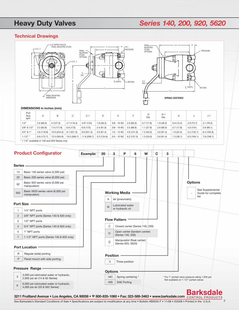
Heavy Duty Valves Series 140, 200, 920, 5620
D A
CYL. 2
E (4 TAPPED HOLES) PANEL MOUNTING STUDS
PANEL MOUNTING STUDS OPTIONAL
CYL. 1
B RETURN
CD
A
PANEL MOUNTING DIMENSIONS
G DIA.
H
PRESSURE
J
F
C L PORTS
J-1
PRESSURE
PANEL MOUNTING STUDS OPTIONAL
G-1DIA.
SPRING CENTERED
C-1
F
C L PORTS RETURN
H
PortSizeNPT
A B C C-1 D E FG
Dia.G-1Dia.
H J J-1
1/4” 2.6 (66.0) 5 (127.0) 4.7 (119.4) 4.87 (124) 1.8 (48.3) 3/8 - 16 NC 2.6 (66.0) 0.7 (17.8) 1.9 (48.3) 0.6 (15.2) 2.9 (73.7) 3.1 (79.3)
3/8” & 1/2” 3.3 (83.8) 7.0 (177.8) 6.8 (173) 6.8 (173) 2.4 (61.0) 3/8 - 16 NC 3.5 (88.9) 1.1 (27.9) 2.6 (66.0) 0.7 (17.8) 4.0 (101) 3.9 (99.1)
3/4” & 1” 4.6 (116.8) 10.0 (254.0) 8.7 (221.0) 9.9 (251.5) 3.6 (91.4) 1/2 - 13 NC 4.8 (121.9) 1.3 (33.0) 3.6 (91.4) 1.0 (25.4) 5.2 (132.1) 6.4 (162.6)
1-1/2” * 6.8 (172.7) 12.0 (304.8) 10.5 (266.7) 11.8 (299.7) 5.3 (134.6) 3/4 - 10 NC 6.2 (157.5) 1.3 (33.0) 3.6 (91.4) 1.5 (38.1) 6.5 (165.1) 7.8 (198.1)
DIMENSIONS in inches (mm)
* 1 1/2” available in 140 and 920 Series only
Example: 20 3 P 6 W C 3
Product Configurator
14 Basic 140 series valve (3,000 psi)
20 Basic 200 series valve (6,000 psi)
92Basic 920 series valve (3,000 psi manipulator)
562Basic 5620 series valve (6,000 psi manipulator)
Series
1 1/4” NPT ports
2 3/8” NPT ports (Series 140 & 920 only)
3 1/2” NPT ports
4 3/4” NPT ports (Series 140 & 920 only)
5 1” NPT ports
7 1-1/2” NPT ports (Series 140 & 920 only)
Port Size
R Regular (side) porting
P Panel mount with side porting
Port Location
33,000 psi lubricated water or hydraulic, 2,000 psi air (14 & 92 Series)
66,000 psi lubricated water or hydraulic, 4,000 psi air (20 & 562 Series)
Pressure Range
C Closed center (Series 140, 200)
OOpen center (tandem center) (Series 140, 200)
Q Manipulator (fl oat center) (Series 920, 5620)
Flow Pattern
-See Supplemental Guide for complete list
Options
3 Three position
Position
Technical Drawings
A Air (pneumatic)
WLubricated water or hydraulic oil
Working Media
-MC Spring centering *
-MS SAE Porting
Options* For 1” ported valve pressure rating 1,500 psi Not available on 1-1/2” ported valves
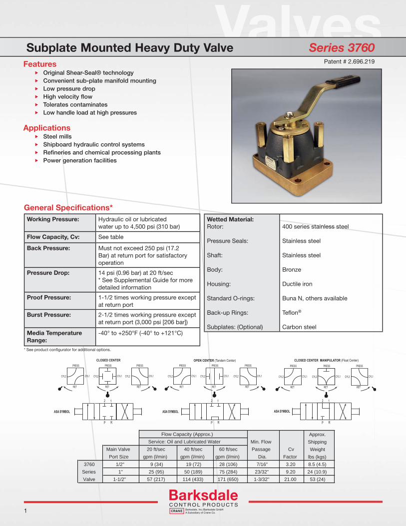
ValvesSubplate Mounted Heavy Duty Valve Series 3760
General Specifications*
1
Flow Capacity (Approx.)Service: Oil and Lubricated Water
Approx.ShippingWeight
lbs (kgs)Main Valve Port Size
20 ft/secgpm (l/min)
40 ft/secgpm (l/min)
60 ft/secgpm (l/min)
Min. Flow Passage
Dia.Cv
Factor3760 1/2" 9 (34) 19 (72) 28 (106) 7/16" 3.20 8.5 (4.5)
Series 1" 25 (95) 50 (189) 75 (284) 23/32" 9.20 24 (10.9)Valve 1-1/2" 57 (217) 114 (433) 171 (650) 1-3/32" 21.00 53 (24)
Working Pressure: Hydraulic oil or lubricatedwater up to 4,500 psi (310 bar)
Flow Capacity, Cv: See table
Back Pressure: Must not exceed 250 psi (17.2 Bar) at return port for satisfactory operation
Pressure Drop: 14 psi (0.96 bar) at 20 ft/sec* See Supplemental Guide for moredetailed information
Proof Pressure: 1-1/2 times working pressure except at return port
Burst Pressure: 2-1/2 times working pressure except at return port (3,000 psi [206 bar])
Media Temperature Range:
-40° to +250°F (-40° to +121°C)
Wetted Material:Rotor:
Pressure Seals:
Shaft:
Body:
Housing:
Standard O-rings:
Back-up Rings:
Subplates: (Optional)
400 series stainless steel
Stainless steel
Stainless steel
Bronze
Ductile iron
Buna N, others available
Tefl on®
Carbon steel
Features Original Shear-Seal® technology Convenient sub-plate manifold mounting Low pressure drop High velocity flow Tolerates contaminates Low handle load at high pressures
Applications Steel mills Shipboard hydraulic control systems Refineries and chemical processing plants Power generation facilities
* See product confi gurator for additional options.
Patent # 2.696.219
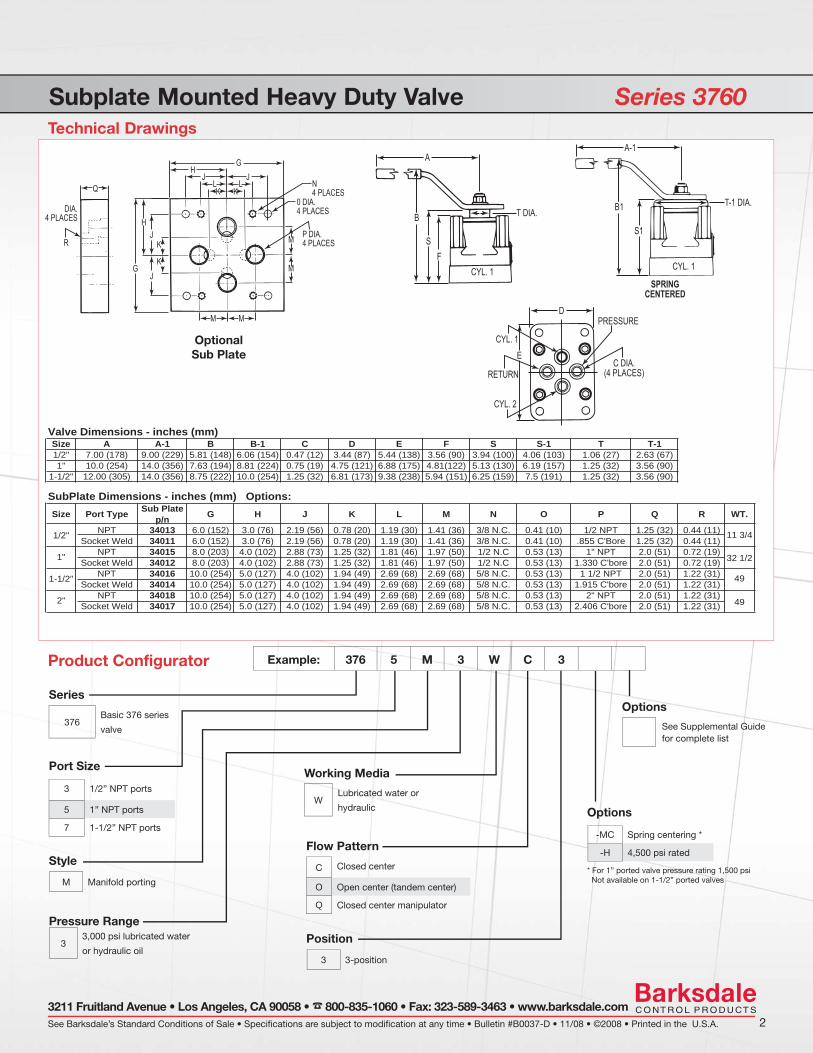
Subplate Mounted Heavy Duty Valve Series 3760Technical Drawings
See Barksdale’s Standard Conditions of Sale • Specifications are subject to modification at any time • Bulletin #B0037-D • 11/08 • ©2008 • Printed in the U.S.A. 23211 Fruitland Avenue • Los Angeles, CA 90058 • 800-835-1060 • Fax: 323-589-3463 • www.barksdale.com
Example: 376 5 M 3 W C 3
Product Configurator
Options
-MC Spring centering *
-H 4,500 psi rated Flow Pattern
C Closed center
O Open center (tandem center)
Q Closed center manipulator
Series
376Basic 376 series
valve
Valve Dimensions - inches (mm)Size A A-1 B B-1 C D E F S S-1 T T-11/2" 7.00 (178) 9.00 (229) 5.81 (148) 6.06 (154) 0.47 (12) 3.44 (87) 5.44 (138) 3.56 (90) 3.94 (100) 4.06 (103) 1.06 (27) 2.63 (67)1" 10.0 (254) 14.0 (356) 7.63 (194) 8.81 (224) 0.75 (19) 4.75 (121) 6.88 (175) 4.81(122) 5.13 (130) 6.19 (157) 1.25 (32) 3.56 (90)
1-1/2" 12.00 (305) 14.0 (356) 8.75 (222) 10.0 (254) 1.25 (32) 6.81 (173) 9.38 (238) 5.94 (151) 6.25 (159) 7.5 (191) 1.25 (32) 3.56 (90)
SubPlate Dimensions - inches (mm) Options: Size Port Type Sub Plate
p/n G H J K L M N O P Q R
1/2" NPT 34013 6.0 (152) 3.0 (76) 2.19 (56) 0.78 (20) 1.19 (30) 1.41 (36) 3/8 N.C. 0.41 (10) 1/2 NPT 1.25 (32) 0.44 (11)Socket Weld 34011 6.0 (152) 3.0 (76) 2.19 (56) 0.78 (20) 1.19 (30) 1.41 (36) 3/8 N.C. 0.41 (10) .855 C'Bore 1.25 (32) 0.44 (11)
1" NPT 34015 8.0 (203) 4.0 (102) 2.88 (73) 1.25 (32) 1.81 (46) 1.97 (50) 1/2 N.C 0.53 (13) 1" NPT 2.0 (51) 0.72 (19)Socket Weld 34012 8.0 (203) 4.0 (102) 2.88 (73) 1.25 (32) 1.81 (46) 1.97 (50) 1/2 N.C 0.53 (13) 1.330 C'bore 2.0 (51) 0.72 (19)
1-1/2" NPT 34016 10.0 (254) 5.0 (127) 4.0 (102) 1.94 (49) 2.69 (68) 2.69 (68) 5/8 N.C. 0.53 (13) 1 1/2 NPT 2.0 (51) 1.22 (31)Socket Weld 34014 10.0 (254) 5.0 (127) 4.0 (102) 1.94 (49) 2.69 (68) 2.69 (68) 5/8 N.C. 0.53 (13) 1.915 C'bore 2.0 (51) 1.22 (31)
2" NPT 34018 10.0 (254) 5.0 (127) 4.0 (102) 1.94 (49) 2.69 (68) 2.69 (68) 5/8 N.C. 0.53 (13) 2" NPT 2.0 (51) 1.22 (31)Socket Weld 34017 10.0 (254) 5.0 (127) 4.0 (102) 1.94 (49) 2.69 (68) 2.69 (68) 5/8 N.C. 0.53 (13) 2.406 C'bore 2.0 (51) 1.22 (31)
11 3/4
32 1/2
49
49
WT.
A
B
SF
T DIA.
CYL. 1
PRESSURE
RETURNC DIA.
(4 PLACES)
A-1
B1
S1
T-1 DIA.
CYL. 1
CYL. 1
CYL. 2
SPRINGCENTERED
D
E
Working Media
WLubricated water or
hydraulic
Pressure Range
33,000 psi lubricated water
or hydraulic oil
Port Size
3 1/2” NPT ports
5 1” NPT ports
7 1-1/2” NPT ports
Position
3 3-position
Style
M Manifold porting
GH
J JL LK K
K
KJ
H
G
R
DIA.4 PLACES
Q N4 PLACES
0 DIA.4 PLACES
P DIA.4 PLACESM
M
MM
J
Options
See Supplemental Guide for complete list
OptionalSub Plate
* For 1” ported valve pressure rating 1,500 psi Not available on 1-1/2” ported valves

ValvesSeries II Valve Models A14 and H14
General Specifications*
1
CYL1
PRESS
CYL2
RET
CYL1
PRESS
CYL2
RET
CYL1
PRESS
CYL2
RET
HANDLE ORENTATION (AS SHOWN CCW)(ACTUATOR PORT 'A' PRESSURIZED)
(PORTS ‘B’ & ‘C’ VENTED)
HANDLE CENTERED(ACTUATOR PORT 'A' & ‘C’ PRESSURIZED)
( PORT ‘B’ VENTED)
HANDLE ORENTATION (AS SHOWN CW)(ACTUATOR PORT 'B' & ‘C’ PRESSURIZED)
(PORTS ‘A’ VENTED)
PR
1 2
A B C
PP R
C2C1 C R
MAIN VALVE
PILOT VALVE 4-WAY PILOT VALVE 3-WAY
3-POSITION FLOW PATTERN SELECTOR(VIEWED FROM SHAFT END)
Flow Capacity (Approx.)Service: Oil and Lubricated Water Approx.
Main Valve 20 ft/sec 40 ft/sec 60 ft/sec Min. Flow Cv ShippingPort Size NPT gpm (l/min) gpm (l/min) gpm (l/min) Passage Dia. Factor Weight
14, 92 1/4" 3 (11) 6 (23) 9 (34) 1/4" 0.95 30Series 3/8" & 1/2" 9 (34) 19 (72) 28 (106) 7/16" 3.20 35Valves 3/4" & 1" 25 (95) 50 (189) 75 (284) 23/32" 9.20 5020, 562 1/4" 3 (11) 6 (23) 9 (34) 1/4" 0.95 30Series 1/2" 5 (19) 10 (38) 15 (57) 5/16" 1.60 35Valves 1" 9 (34) 19 (72) 28 (106) 7/16" 3.20 50
Working Pressure: Hydraulic up to 3,000 or 6,000 psi (206 bar or 413 bar)Air up to 4,000 psi (276 bar)
Flow Capacity, Cv: See table
Back Pressure: Must not exceed 250 psi (17.2 bar) at return port for satisfactory operation
Proof Pressure: 1-1/2 times working pressure except at return port
Burst Pressure: 2-1/2 times working pressure except at return port (3,000 psi [206 bar])
Pressure Drop (all Valves):
20 ft/s –14 psi; 6.1 m/s – 1 bar40 ft/s – 58 psi; 12.2 m/s – 4.0 bar60 ft/s – 130 psi; 18.3 m/s – 9.0 bar
Media Temperature Range:
-40° to +250°F (-40° to +121°C)
Wetted Materials:Standard O-Rings:Back-up Rings:
400 Series Stainless SteelBuna NTefl on®
Handle Detent: All valves have 3-position detents formanual shift to Center position
Panel Mounting: Standard for 1/4”- 1/2” valvesConsult Factory for 3/4” & 1” valves
Features Original Shear-Seal® technology Integrated actuator 2- and 3-position Superior shifting performance High velocity flow Compact design Corrosion resistant materials
Applications Land-based & offshore oil drilling controls
BOP control units Steel mills Shipboard hydraulic control systems Industrial hydraulic power units Refineries and chemical processing plants
- Main Valve - Pilot Actuator
Working Pressure:Air:
Hydraulic (2-position only):
80 psi (5.2 bar) minimum250 psi (17.2 bar) maximum500 psi (34 bar) minimum 1,500 psi (103 bar) maximum
Porting: 1/4” NPT
Media Temperature Range: -40° to +250°F (-40° to +121°C)
Speed of Operation: Shift time for 90° must be 1/2 second minimum to avoid damage
Body, Housing, End Plate: Al-Ni Bronze
Cylinder: Amalga tubing (air)Stainless steel (hydraulic)
Shaft: Stainless steel
Hardware: Stainless steel
Handle: Zinc plated alloy steel
Rotor, Seals: 400 series stainless steel
HANDLE ORENTATION (AS SHOWN CCW)(ACTUATOR PORT 'A' PRESSURIZED)
CYL1
PRESS
CYL2
RET
HANDLE ORENTATION (AS SHOWN CW)(ACTUATOR PORT 'B' PRESSURIZED)
CYL1
PRESS
CYL2
RET
PR
1 2
A B
P R
1 2
MAIN VALVE
PILOT VALVE 4-WAY
2-POSITION FLOW PATTERN SELECTOR(VIEWED FROM SHAFT END)
HANDLE ORENTATION (AS SHOWN CW)(ACTUATOR PORT 'B' PRESSURIZED)
CYL1
PRESS
CYL2
RET
HANDLE CENTERED(MANUALLY OVERRIDE ONLY)
CYL1
PRESS RET
HANDLE ORENTATION (AS SHOWN CW)(ACTUATOR PORT 'A' PRESSURIZED)
CYL1
PRESS
CYL2
RET
PR
11 22
A B
P R
1 2
MAIN VALVE
PILOT VALVE 4-WAY
PR
1 2
CLOSED CENTER MANIPULATOR FLOW PATTERN(VIEWED FROM SHAFT END)
Patent# US D521.598 S Patent# US D521.599 S
* See product confi gurator for additional options.

Series II Valve Models A14 and H14Technical Drawings
1 See Supplemental Guide for the appropriate “Z number”
See Barksdale’s Standard Conditions of Sale • Specifications are subject to modification at any time • Bulletin #B0022-I • 02/09 • ©2009 • Printed in the U.S.A. 23211 Fruitland Avenue • Los Angeles, CA 90058 • 800-835-1060 • Fax: 323-589-3463 • www.barksdale.com
Example: A 20 3 R 6 W C 3Product Confi gurator
Options
- B Position Indicator
- C 3 x 2 converter
-H 4,500 psi working pressure
-M 5,000 psi working pressure
-D Diverter fl ow pattern
-MS SAE Porting
-Zxx Optional O-ring material1
Flow Pattern
C Closed center
O Open center (tandem center)
Q
Closed center manipulator Standard on 92 and 562 seriesOptional on 376 Series in closed center onlyNot available on 14 and 20 Series
Actuator Media
A Air cylinder
H Hydraulic cylinder
Working Media
W Lubricated water or hydraulic oil
A Air or other gasses
Series
14 3,000 psi (206 bar), 4-way selector or diverter
20 6,000 psi (412 bar), 4-way selector or diverter
92 3,000 psi (206 bar), 4-way closed center manipulator
562 6,000 psi (412 bar), 4-way closed center manipulator
376 3,000 psi (206 bar), 4-way sub-plate mount
A
D
D
L
QH
J
U
T
KKG
F
C
CB
A
E
PPANEL MOUNTN
(4 PLACES)
evlaV noitisoP-3evlaV noitisoP-2
B C
B
AA
L
HR
S
KG
F
P
M
Port Size
1 1/4” NPT
2 3/8” NPT (14 and 92 series only)
3 1/2” NPT
4 3/4” NPT (14 and 92 series only)
5 1” NPT
Port Location
R Regular side porting
M Manifold porting (376 series only)
Pressure Range
33,000 psi lubricated water or hydraulic oil, 2,000 psi air (14, 92 & 376 Series)
66,000 psi lubricated water or hydraulic oil, 4,000 psi air (20 & 562 series)
Position
2 2-position actuator, 90º rotation
3 3-position actuator
3/4”, 1"
Optional O-ring Material
-Zxx See supplemental guide
Porting A B C D E F G H J K L M N P Q R S T U
1/4” NPT2.75
(60.3)10.38
(254.0)2.0
(50.8)1.0
(25.4)5.0
(127.0)5.72
(146.1)4.25 (108)
.50 (12.7)
3.34(85)
3.25 (82.6)
1.94 (49.2)
9.43 (231.7)
3/8-16UNC 4.88
(124.0)7.44
(189.0)2.44 (62)
3.75 (95.3)
8.44 (214.4)
10.468 (265.9)
3/8” & 1/2” NPT
3.406 (86.5)
10.937 (277.8)
2.625 (66.7)
1.312 (33.3)
5.0 (127.0)
6.25 (158.8)
4.75 (120.65)
.688 (17.46)
3.531 (89.7)
3.25 (82.6)
1.94 (49.2)
9.531 (242.1)
3/8-16UNC 5.50
(139.7)7.85
(199.3)2.56
(65.1)3.88
(98.4)8.688
(220.7)10.25
(260.4)
3/4” & 1” NPT
4.781 (121.4)
14.375 (365.1)
3.625 (92)
1.812 (46)
9.0 (228.6)
8.75 (222.3)
6.562 (166.6)
1.0 (25.4)
4.25 (108)
3.50 (88.9)
3.0 (76.2)
12.0 (482.0)
1/2-13UNC 7.562
(192.0)10.125 (257.0)
NA NA NA NA
3.40PANEL CUTOUT
9
D
C
D
9.509
B
PANELMOUNTN(3)
PANEL MOUNTING HOLES2X 1/2-13 UNC-2B 1.00
1/4”, 3/8”, 1/2”

ValveExplosion Proof Position Indicator Model 371MT7
Features Fits all Series II valves 2 position and 3 position 30 VDC max, 500 mA (PLC compatible) Designed for Division I and I.S. use UL & ATEX approved NEMA 4X, IP67
Applications Valve status output BOP closing unit ‘OPEN-CLOSE’ signal Hydraulic power units
General Specifications*
1
Housing Material: Stainless steel
Enclosure: NEMA 4X, IP67
Electrical Rating:
Electrical Connection:
Electrical Cable:
Maximum Contact Resistance:
Dielectric:
30 VDC max, 500 mA (carry current)
½” NPT rotating female conduit connection with 3 ft (36 in) cable
UL listing, 4 conductors, 22 AWG TPE fl ame resistant jacket. Resistance to oils, fuels, and solvents
100 milliohms
100 megaohms minimum (@ 250 VDC)
Switch Type: SPST
Approvals: Division 1, Class 1, Groups A, B, C & DEx d ia IIc T6Intrinsically safe to 24 VDC, 50 mA, 10 W
Valve Position Feedback:
2-Way3-Way
Operating Temperature: -40 to +185°F (-40 to 85°C)
Installation Instructions: - Connect electrical wires - Lightly lubricate the position indicator O-rings (2)- Fully insert switch into stop screw- Rotate position indicator for optimum cable exit- Secure set screws (2)
Weight: 2 lbs.
* See Product Confi gurator for additional options.
Reliable valve position feedback for Series II Valve
Wiring Code
UL & ATEX approved
COMMON/BLACK
CASE GROUND - DRAIN
CYLINDER 2/ORANGE
CENTER/RED
CYLINDER 1/BROWN
Explosion Proof Position Indicator Model 371MT7
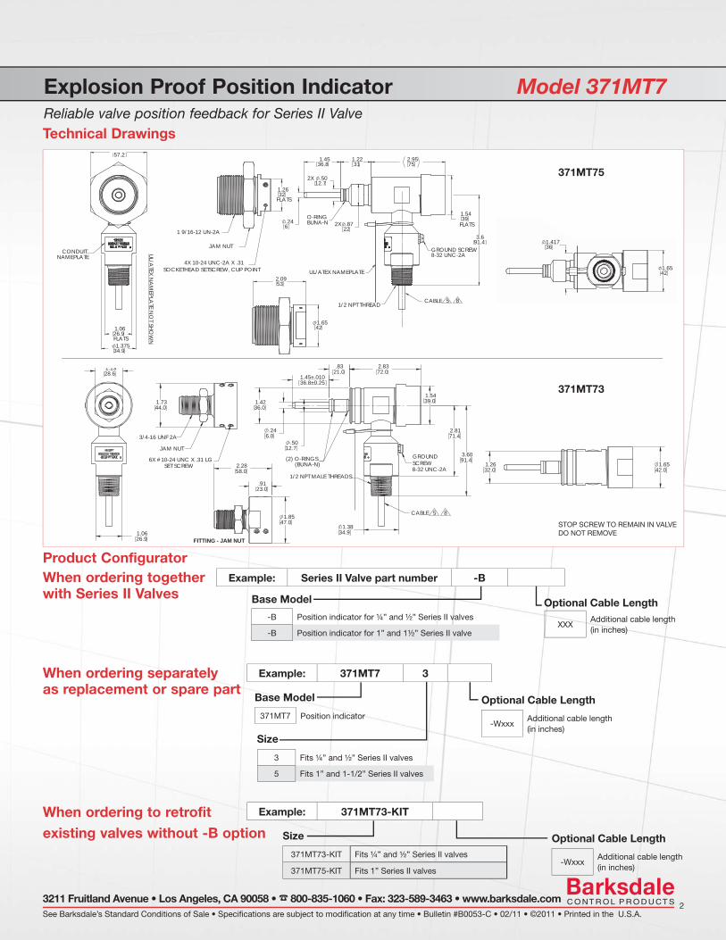
Technical Drawings
Product ConfiguratorExample: Series II Valve part number -B
See Barksdale’s Standard Conditions of Sale • Specifications are subject to modification at any time • Bulletin #B0053-C • 02/11 • ©2011 • Printed in the U.S.A.2
3211 Fruitland Avenue • Los Angeles, CA 90058 • 800-835-1060 • Fax: 323-589-3463 • www.barksdale.com
Base Model
371MT7 Position indicator
Size
371MT73-KIT Fits ¼” and ½” Series II valves
371MT75-KIT Fits 1” Series II valves
Optional Cable Length
-WxxxAdditional cable length (in inches)
Optional Cable Length
-WxxxAdditional cable length (in inches)
Size
3 Fits ¼” and ½” Series II valves
5 Fits 1” and 1-1/2” Series II valves
Reliable valve position feedback for Series II Valve
.9123.0
2.2858.0
1.1328.6
1.0626.9
CABLE 5 8
3/4-16 UNF 2A
JAM NUTGROUNDSCREW8-32 UNC-2A
1/2 NPT MALE THREADS
6X #10-24 UNC X .31 LG SET SCREW
(2) O-RINGS (BUNA-N)
1.45±.01036.8±0.25
.246.0
2.8171.4
3.6091.4
1.3834.9
2.8372.0
1.5439.0
.5012.7
.8321.0
1.4236.0
1.7344.0
FITTING - JAM NUT
1.8547.0
.9123.0
2.2858.0
1.2632.0
1.6542.0
CABLE 5 8
1.3834.9
When ordering together with Series II Valves
When ordering separately as replacement or spare part
Example: 371MT7 3
Example: 371MT73-KITWhen ordering to retrofit existing valves without -B option
STOP SCREW TO REMAIN IN VALVEDO NOT REMOVE
8
4X 10-24 UNC-2A X .31
BUNA-N
GROUND SCREW
1/2 NPT THREAD
1 9/16-12 UN-2A
8-32 UNC-2A
O-RING
JAM NUT
SOCKETHEAD SETSCREW, CUP POINT
CABLE 5
UL/ATEX NAMEPLATE
.87
.50
3.691.4
31
2X
1.221.45
12.7
22
36.8
2X
.246
391.54
75
FLATS
2.95
1.26
FLATS32
1.6542
1.41736
1.6542
2.0953
CONDUITNAMEPLATE
UL/ATEX N
AM
EPLATE N
OT SH
OW
N
26.9FLATS1.375
1.06
34.9
57.2
1.6542
2.0953
1.41736
1.6542
371MT75
371MT73
-B Position indicator for ¼” and ½” Series II valves
-B Position indicator for 1” and 1½” Series II valve
Base Model
XXXAdditional cable length (in inches)
Optional Cable Length

Valves
* See product confi gurator for additional options and Supplemental Guide for more detailed information.
1
Working Pressure: Standard to 10,000 psi (690 bar) Optional to 15,000 psi (1,034 bar) (on 1/4” model only)
Flow Capacity, Cv: See table
Back Pressure: Must not exceed 250 psi (17.2 bar) at return port for satisfactory operation
Pressure Drop: 14 psi (0.96 bar) at 20 ft/s
Proof Pressure: 1-1/2 times working pressure except at return port
Burst Pressure: 2-1/2 times working pressure except at return port (3,000 psi [206 bar]) maximum
Media Temperature Range:
-40° to +250°F (-40° to +121°C)
Rotor: 400 series stainless steel
Pressure Seals: Stainless steel
Shaft: Stainless steel
Body, Housing: 300 series stainless steel
Standard O-ring: Buna N
Back-up Rings: Tefl on®
Flow Capacity (Approx.)
Service: Oil and Lubricated Water
Main Valve Port Size
20 ft/secgpm (l/min)
40 ft/secgpm (l/min)
60 ft/secgpm (l/min)
Min. Flow Passage Dia.
CvFactor
Approx. ShippingWeight lbs (kgs)
1/4” 4 (15) 8 (30) 12 (45) 9/32” 0.95 13.5 (6.2)
1/2” 4 (15) 8 (30) 12 (45) 9/32” 0.95 13.5 (6.2)
1” 9 (34) 19 (72) 28 (106) 7/16” 3.20 29.5 (13.5)
High Pressure Valve Series 4140
General Specifications*
Features Original Shear-Seal® technology Stainless steel construction Low pressure drop High velocity flow Pressures to 15,000 psi Low handle load
Applications Offshore drilling equipment Refineries and chemical processing plants Gas compression systems Marine umbilical reels
See Barksdale’s Standard Conditions of Sale • Specifications are subject to modification at any time • Bulletin #B0038-E • 11/08 • ©2008 • Printed in the U.S.A. 2
3211 Fruitland Avenue • Los Angeles, CA 90058 • 800-835-1060 • Fax: 323-589-3463 • www.barksdale.com
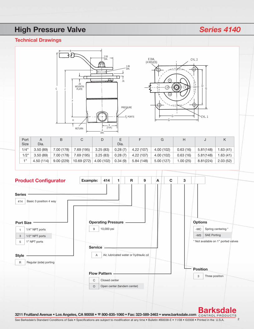
Technical Drawings
Example: 414 1 R 9 A C 3
Product Confi gurator
Series
414 Basic 3 position 4 way
B
2.50DIA.
1.06DIA.
.31
.25MOUNTIN
PLATEJC
PRESSURE
F
H
RETURNA
DIA.
PORTSCL
K(TYP.)
D
D
G
G
CYL. 1
E DIA.(4 HOLES)
CYL. 2
High Pressure Valve Series 4140
PortSize
ADia.
B C D EDia.
F G H J K
1/4” 3.50 (89) 7.00 (178) 7.69 (195) 3.25 (83) 0.28 (7) 4.22 (107) 4.00 (102) 0.63 (16) 5.81(148) 1.63 (41)
1/2” 3.50 (89) 7.00 (178) 7.69 (195) 3.25 (83) 0.28 (7) 4.22 (107) 4.00 (102) 0.63 (16) 5.81(148) 1.63 (41)
1” 4.50 (114) 9.00 (229) 10.69 (272) 4.00 (102) 0.34 (9) 5.84 (148) 5.00 (127) 1.00 (25) 8.81(224) 2.03 (52)
Port Size
1 1/4” NPT ports
3 1/2” NPT ports
5 1” NPT ports
Style
R Regular (side) porting
Operating Pressure
9 10,000 psi
Service
A Air, lubricated water or hydraulic oil
Flow Pattern
C Closed center
O Open center (tandem center)
Position
3 Three position
Options
-MC Spring centering *
-MS SAE Porting
* Not available on 1” ported valves
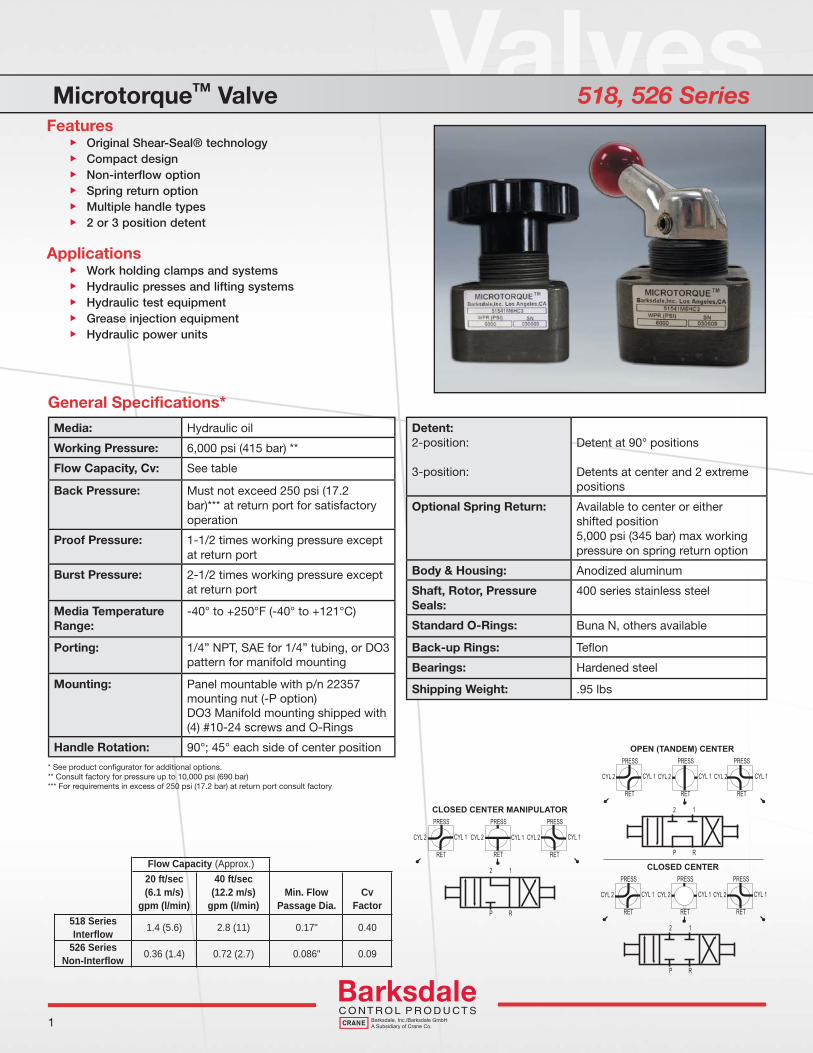
ValvesMicrotorqueTM Valve 518, 526 Series
General Specifications*
1
Flow Capacity (Approx.)20 ft/sec(6.1 m/s)
gpm (l/min)
40 ft/sec(12.2 m/s)
gpm (l/min)Min. Flow
Passage Dia.Cv
Factor518 SeriesInterflow 1.4 (5.6) 2.8 (11) 0.17" 0.40
526 SeriesNon-Interflow 0.36 (1.4) 0.72 (2.7) 0.086" 0.09
Media: Hydraulic oil
Working Pressure: 6,000 psi (415 bar) **
Flow Capacity, Cv: See table
Back Pressure: Must not exceed 250 psi (17.2 bar)*** at return port for satisfactory operation
Proof Pressure: 1-1/2 times working pressure except at return port
Burst Pressure: 2-1/2 times working pressure except at return port
Media Temperature Range:
-40° to +250°F (-40° to +121°C)
Porting: 1/4” NPT, SAE for 1/4” tubing, or DO3pattern for manifold mounting
Mounting: Panel mountable with p/n 22357mounting nut (-P option) DO3 Manifold mounting shipped with(4) #10-24 screws and O-Rings
Handle Rotation: 90°; 45° each side of center position
Features Original Shear-Seal® technology Compact design Non-interflow option Spring return option Multiple handle types 2 or 3 position detent
Applications Work holding clamps and systems Hydraulic presses and lifting systems Hydraulic test equipment Grease injection equipment Hydraulic power units
Detent:2-position:
3-position:
Detent at 90° positions
Detents at center and 2 extremepositions
Optional Spring Return: Available to center or either shifted position5,000 psi (345 bar) max workingpressure on spring return option
Body & Housing: Anodized aluminum
Shaft, Rotor, Pressure Seals:
400 series stainless steel
Standard O-Rings: Buna N, others available
Back-up Rings: Tefl on
Bearings: Hardened steel
Shipping Weight: .95 lbs
CYL 2 CYL 1
PRESS
RET
CYL 2 CYL 1
PRESS
RET
CYL 2 CYL 1
PRESS
RET
CLOSED CENTER
2
P
1
R
CYL 2 CYL 1
PRESS
RET
CYL 2 CYL 1
PRESS
RET
CYL 2 CYL 1
PRESS
RET
OPEN (TANDEM) CENTER
2
P
1
R
CYL 2 CYL 1
PRESS
RET
CYL 2 CYL 1
PRESS
RET
CYL 2 CYL 1
PRESS
RET
CLOSED CENTER MANIPULATOR
2
P
1
R
* See product confi gurator for additional options.** Consult factory for pressure up to 10,000 psi (690 bar)*** For requirements in excess of 250 psi (17.2 bar) at return port consult factory

MicrotorqueTM Valve 518, 526 SeriesTechnical Drawings
1 5,000psi max working pressure for spring return option2 See supplemental guide for the appropriate “Z number”
See Barksdale’s Standard Conditions of Sale • Specifications are subject to modification at any time • Bulletin #B0020-E • 09/07 • ©2007 • Printed in the U.S.A. 23211 Fruitland Avenue • Los Angeles, CA 90058 • 800-835-1060 • Fax: 323-589-3463 • www.barksdale.com
Example: 518 41M 6 H C 3
Product Confi gurator
Options
-MC Spring return to center 1
-MRSpring return to right
(Pressure port to C1) 1
-MLSpring return to left
(Pressure port to C2) 1
-MS SAE porting for 1/4” tubing
-EBlack knob (not available
with spring return)
-PPanel mounting nut p/n
22357
Flow Pattern
C 4-way closed center
O 4-way open center
M4-way manipulator
Closed center
Series
518 Interfl ow
526 Non-interfl ow
Detent Position
2 2-position 90° rotation
3 3-position
Porting
21R Regular (side) porting
41M Manifold porting (D03)
61SStraight (bottom)
Porting
G
J(4 PLACES)
HC
D
EF
Q
1.312(33.3)
2.375 (60.3)
Q
A
B
Regular and Straight Porting
Optional Knob (-E)
PANEL
PANEL CUTOUT
N
M
KL
1.437
ø 1.250(31.8)
(37) P
.250(7)
MAX. PANELTHICKNESS
KL
M
1.0(25)
1.062(27)
.562 (14)
1.125(29)
.562 (14)
1.125(29)
Ø.16 X .16 DEEP
"CYL.2" PORT
"CYL.1" PORT
"CYL.1" PORT
"CYL.1" PORT
"RETURN" PORT
MANIFOLD PORTING(Mounting per DO3 Spec)
GNITROP THGIARTSGNITROP RALUGER
.610(15.9)
1.220(31.0)
.690(17.5)
.345(8.8)
.206 THRU (5.2)4 PLACES
"RETURN" PORT
1.594(40.5)
.450(11.4)
.410(10.4)
.820 (20.8)
1.260(32.5).640
(16.3)
"PRESSURE"PORT
"PRESSURE"PORT "PRESSURE"
PORT
"RETURN" PORT
"CYL.2" PORT
"CYL.2" PORT
(SIDE) (BOTTOM)
.850(21.6)
ø 1.250(31.8)
P
J(4 PLACES)
Series Porting A B C D E F G H J K L M N P Q
21R , 61S Porting 1.968 2.031 1.281 .640 1.594 .850 1.219 .610 1/4-28 3.812 1.437 1.781 .437 1.375 3.125518 (50.0) (51.6) (32.5) (16.3) (40.5) (21.6) (31.1) (15.5) UNF (96.8) (36.5) (45.2) (11.1) (34.9) (79.4)or 41M Manifold Porting 3.1251.3751.4061.43710-24 3.8752.0311.968
526 )34.9()29.0()36.5()98.4UNC ()6.15()0.05(
Spring Return Option 5.4372.5005.562)138.1()3.36()141.3(
(79.4)
Pressure Range
6 6,000 psi
Working Media
H Hydraulic oil
Position
-Zxx Optional O-ring material 2

Valves
1
Working Pressure: Air (pneumatic) up to 1,500 psi (103 bar)Hydraulic oil or lubricated water, up to 3,000 psi (206 bar)
Pressure Drop: 9 psi at 2.5 gpm32 psi at 4 gpm(For more detailed pressure drop and fl ow capacity information, see valve supplemental guide)
Max. Fluid Velocity: 20ft/sec (6.1 m/sec)
Cv Factor: 0.7
Min. Flow Diameter: 7/32 in. (5.6mm)
Back Pressure: Must not exceed 250 psi (17.2 bar) at return port for satisfactory operation
Proof Pressure: 1-1/2 times working pressure except at return port
Burst Pressure: 2-1/2 times working pressure except at return port (3000 psi [206 bar])
Media Temperature Range:
-40° to +250°F (-40° to +121°C)
Electrical Data:Solenoid Voltage:
Current - Inrush:
Current - Holding:
115V AC at 60 Hz(Alternative AC & DC voltages are available).
16.8 amps
1.52 amps
Voltage Tolerance: ±10% of rated voltage
Solenoid Rating: Continuous duty
Material of Construction:Slide:
Body & Pressure Fittings:
Pressure Seals:
Standard O-Ring:
Back-up Rings:
400 series stainless steel
Bronze
Stainless Steel
Buna N
Tefl on®
Shipping Weight: 11.5 Lbs. / Explosion-Proof 20 Lbs.
4-Way Flow Pattern
These Flow Patterns are obtainable from a single Standard Valve. Every valve is shipped with the necessary plugs *To acheive the desired flow pattern, plug ports as shown.
3-Way Shut-Off Diverter
*Plug Port Marked “X”
Norm. Open
Cyl. 2
Norm. Closed
Cyl. 1
Norm. Open
Ret. & Cyl. 2
Norm. Closed
Ret. & Cyl. 1 Ret. None
Normal Position
Spring Loaded
Energized Position
ASA Symbol
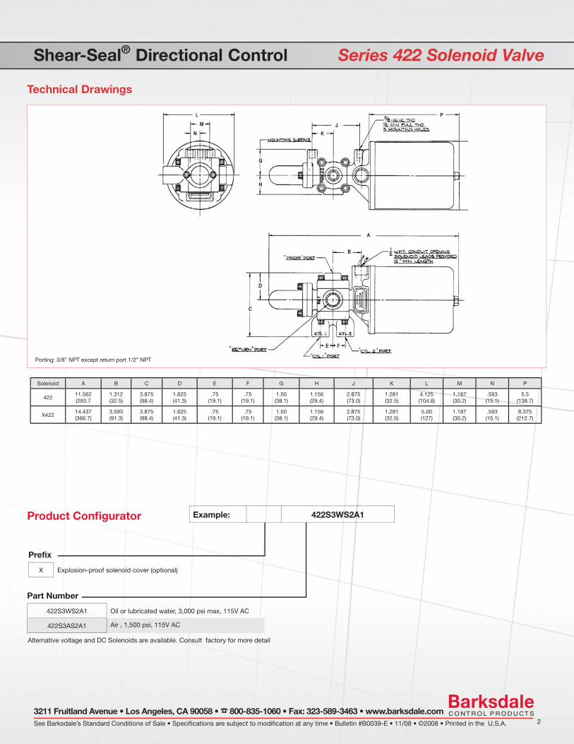
Shear-Seal® Directional Control Series 422 Solenoid Valve
General Specifications**
* Less than four cc per minute** See product confi gurator for additional options.
Features Original Shear-Seal® technology Explosion-Proof option Zero-leakage* Spring close with no power Flexible flow patterns Tolerates contaminates
Applications Mining operations Offshore oil platforms Refineries and chemical processing plants Power generation facilities Air or hydraulic test equipment
See Barksdale’s Standard Conditions of Sale • Specifications are subject to modification at any time • Bulletin #B0039-E • 11/08 • ©2008 • Printed in the U.S.A. 2
3211 Fruitland Avenue • Los Angeles, CA 90058 • 800-835-1060 • Fax: 323-589-3463 • www.barksdale.com
Shear-Seal® Directional Control Series 422 Solenoid Valve
Porting: 3/8” NPT except return port 1/2” NPT
Technical Drawings
Example: 422S3WS2A1
Product Confi gurator
Alternative voltage and DC Solenoids are available. Consult factory for more detail
Part Number
422S3WS2A1 Oil or lubricated water, 3,000 psi max, 115V AC
422S3AS2A1 Air , 1,500 psi, 115V AC
Prefix
X Explosion-proof solenoid cover (optional)
Solenoid A B C D E F G H J K L M N P
42211.562(293.7
1.312(32.5)
3.875(98.4)
1.625(41.3)
.75(19.1)
.75(19.1)
1.50(38.1)
1.156(29.4)
2.875(73.0)
1.281(32.5)
4.125(104.8)
1.187(30.2)
.593(15.1)
5.5(138.7)
X42214.437(366.7)
3.593(91.3)
3.875(98.4)
1.625(41.3)
.75(19.1)
.75(19.1)
1.50(38.1)
1.156(29.4)
2.875(73.0)
1.281(32.5)
5.00(127)
1.187(30.2)
.593(15.1)
8.375(212.7)

Valves1/2” Heavy Duty Hydraulic Regulator Series 20313
General Specifications*
* See product confi gurator for additional options.
1
Pressure:Supply/Inlet Pressure:
Regulated Pressure Range:High SensitivityFull Range
Regulated Pressure Range“F” Prefi x Pneumatic failsafe motor:High SensitivityFull Range
Regulated Pressure Range“G” Prefi x Hydraulic failsafe motor:High SensitivityFull Range
Fluid Temperature Range:
Proof Pressure:
5,000 psi (345 bar)
300 - 1600 psi (21 -110 bar)300 - 3000 psi (21 - 207 bar)
300 - 1600 psi (21 -110 bar)300 - 3000 psi (21 - 207 bar)
300 - 1600 psi (21 -110 bar)300 - 3000 psi (21 - 207 bar)
-40° to +250°F (-40° to +121° C)
7,500 psi (517 bar)
Flow:Flow Rate:
Cv Inlet:
Cv Vent:
45 GPM (@ 50/ft/s)
6.7
6.7
Porting:Inlet:
Outlet:
Vent:
Bleed Port:
1/2” NPT Standard, SAE Option
1/2” NPT Standard, SAE Option
1/2” NPT Standard, SAE Option
1/4” Dia. hole
Features Original Shear-Seal® technology Self adjusting High flow capacity Tolerates contaminated media Fail-safe motor control options
Applications BOP Control Units Coiled tube reels Oil and gas systems Pressure sensitive applications
Materials of Construction:Body:
Flanges:
Spring Tower Housing:Manual:Pneumatic Motor model:Hydraulic Motor model:
Standard O’ring Material:
Socket Head Screws:
Wetted Parts:
Stainless Steel (standard)
Carbon Steel (standard)Option: Stainless steel
Phosphate coated alloy steel (std.)Phosphate coated alloy steel (std.)Phosphate coated alloy steel (std.)Option: Stainless Steel
Buna N
Zinc plated alloy steel (standard)Option: Stainless steel
Stainless steel & bronze
Pneumatic Pilot Motor (“F” prefi x):Pilot Motor Working Pressure:
Porting:
Operating Temperature Range:
80 - 120 psi (5.5 - 8.3 bar)
1/4” NPT
32° to +250°F (0° to +120°C)
Hydraulic Pilot Motor (“G” prefi x):Pilot Motor Working Pressure:
Porting:
Operating Temperature Range:
400 - 1600 PSI (6.9 - 110 bar)
SAE for 3/8” Tube (Size -6)
-40° to +250°F (-40° to +121°C)
Approximate Shipping Weight:Manual:
Pneumatic or Hydraulic Motor:
21 lbs. (9.5 kg)
44 lbs. (20.0 kg)

1/2” Heavy Duty Hydraulic Regulator Series 20313
Technical Drawings
See Barksdale’s Standard Conditions of Sale • Specifications are subject to modification at any time • Bulletin #B0026-F • 03/11 • ©2011 • Printed in the U.S.A. 23211 Fruitland Avenue • Los Angeles, CA 90058 • 800-835-1060 • Fax: 323-589-3463 • www.barksdale.com
Example: 20313S6WQ2
Product Confi gurator
Option
Blank NPT porting
-MS SAE porting
-SS Stainless Steel Flanges & Trim
Adjustment Method
Blank Manual
F Pneumatic motor
G Hydraulic motor
15.188
2.250
1.750
1.500
2.500
2.375
4.750
1/8” NPTBLEED PORT
.250.2502.250
Series
20313S6WQ2 1/2” Shear-Seal Regulator
7.125
4.500
3.500
19.125MAX(485.8)
9.281(235.7)
7.968(202.2)
18.938(481)
1.75(44.5)
1.562
2.500(63.5)
2.500(63.5)
Regulated Pressure Range (Manual)
Blank High sensitivity 300 - 1600 psi (21 -110 bar)
-1 Full range 300 - 3000 psi (21 - 207 bar)
Regulated Pressure Range (Failsafe) (F or G models)
Blank High sensitivity 300 - 1600 psi (21 -110 bar)
-1 Full range 300 - 3000 psi (21 - 207 bar)
Dimensions in inches (mm)

Valves3/4” Hydraulic Regulator Series 20415
General Specifications*
* See product confi gurator for additional options.
1
Features Original Shear-Seal® technology Self adjusting High flow capacity Tolerates contaminated media Fail-safe motor control options Self venting
Applications Coiled tube reels Land-based oil drilling controls BOP control units
Pressure:Supply/Inlet Pressure:
Regulated Pressure Range:High SensitivityFull Range
Regulated Pressure Range“F” Prefi x Pneumatic failsafe motor:High SensitivityFull Range
Regulated Pressure Range“G” Prefi x Hydraulic failsafe motor:High SensitivityFull Range
Fluid Temperature Range:
Proof Pressure:
3,000 psi (207bar)
500 - 1600 PSI (34 -110 bar)500 - 2800 PSI (34 - 193 bar)
500 - 1600 PSI (34 -110 bar)500 - 2800 PSI (34 - 193 bar)
500 - 1600 PSI (34- 110 bar)500 - 2800 PSI (34 - 193 bar)
-40° to +250°F (-40° to +121°C)
4,500 PSI (310 bar)
Flow:Flow Rate:
Cv Inlet:
Cv Vent:
70 GPM (@ 50 ft/s)
9.8
0.6
Porting:Inlet 1:
Outlet (regulated):
Vent:
Gauge Port:
1” NPT Standard, SAE Optional
1” NPT Standard, SAE Optional
1/2” NPT Standard, SAE Optional
3/8” NPT Standard, SAE Optional
Materials of Construction:Body:
Flanges:
Spring Tower:ManualPneumatic Motor modelHydraulic Motor model
Standard O’ring Material:
Socket Head Screws:
Wetted Parts:
Phosphate coated alloy steel (std.)Option: Stainless steel
Phosphate coated alloy steel (std.)Option: Stainless steel
Phosphate coated alloy steel (std.)Painted alloy steel (std.)Painted alloy steel (std.)Option: Stainless steel
Buna N
Zinc plated alloy steel (std.)Option: Stainless steel
Stainless steel & bronze
Pneumatic Pilot Motor (“F” prefi x):Pilot Motor Working Pressure:
Porting:
Operating Temperature Range:
80 - 120 PSI (5.5 - 8.3 bar)
1/4” NPT
32° to +250°F (0° to +120°C)
Hydraulic Pilot Motor (“G” prefi x):Pilot Motor Working Pressure:
Porting:
Operating Temperature Rating:
400 - 1600 PSI (6.9 - 110 bar)
SAE for 3/8” Tube (Size -6)
-40° to +250°F (-40° to +121°C)
Approximate Shipping Weight:Manual:
Pneumatic or Hydraulic Motor:
47 lbs. (21.3 kg)
70 lbs. (31.8 kg)

3/4” Hydraulic Regulator Series 20415
Technical Drawings
See Barksdale’s Standard Conditions of Sale • Specifications are subject to modification at any time • Bulletin #B0025-G • 02/11 • ©2011 • Printed in the U.S.A. 23211 Fruitland Avenue • Los Angeles, CA 90058 • 800-835-1060 • Fax: 323-589-3463 • www.barksdale.com
6.063
5.188
3.312
2.875
.500
1.375
4.562
6.875
21.500
7.125
3.500
2.125
1.562
25.625(652)
25.625(652)
16.625(423)4.500
Example: 20415S3WQ2
Product Confi gurator
Adjustment Method
Blank Manual
F Pneumatic failsafe motor
G Hydraulic failsafe motor
Series
20415S3WQ2 1” Pressure regulator
Regulated Pressure Range (Manual)
Blank High sensitivity 500 - 1600 psi (34 - 110 bar)
-1 Full range 500 - 2800 psi (34 - 193 bar)
Regulated Pressure Range (Failsafe) F & G Models
Blank High sensitivity 500 - 1600 psi (34 - 110 bar)
-1 Full range 500 - 2800 psi (34 - 193 bar)
Option
Blank NPT porting
-MS SAE porting
-SS Stainless steel fl anges & trim
Dimensions in inches (mm)
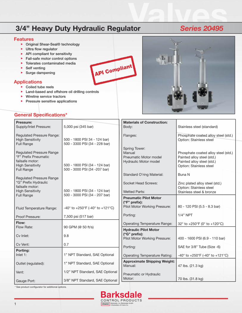
Valves3/4” Heavy Duty Hydraulic Regulator Series 20495
General Specifications*
1
Features Original Shear-Seal® technology Ultra flow regulator API compliant for sensitivity Fail-safe motor control options Tolerates contaminated media Self venting Surge dampening
Applications Coiled tube reels Land-based and offshore oil drilling controls Wireline service tractors Pressure sensitive applications
* See product confi gurator for additional options.
Pressure:Supply/Inlet Pressure:
Regulated Pressure Range:High SensitivityFull Range
Regulated Pressure Range“F” Prefi x Pneumatic failsafe motor:High SensitivityFull Range
Regulated Pressure Range“G” Prefi x Hydraulic failsafe motor:High SensitivityFull Range
Fluid Temperature Range:
Proof Pressure:
5,000 psi (345 bar)
500 - 1800 PSI 34 - 124 bar)500 - 3300 PSI (34 - 228 bar)
500 - 1800 PSI (34 - 124 bar)500 - 3000 PSI (34 -207 bar)
500 - 1800 PSI (34 - 124 bar)500 - 3000 PSI (34 - 207 bar)
-40° to +250°F (-40° to +121°C)
7,500 psi (517 bar)
Flow:Flow Rate:
Cv Inlet:
Cv Vent:
90 GPM (@ 50 ft/s)
9.8
0.7
Porting:Inlet 1:
Outlet (regulated):
Vent:
Gauge Port:
1” NPT Standard, SAE Optional
1” NPT Standard, SAE Optional
1/2” NPT Standard, SAE Optional
3/8” NPT Standard, SAE Optional
Materials of Construction:Body:
Flanges:
Spring Tower:ManualPneumatic Motor modelHydraulic Motor model
Standard O’ring Material:
Socket Head Screws:
Wetted Parts:
Stainless steel (standard)
Phosphate coated alloy steel (std.)Option: Stainless steel
Phosphate coated alloy steel (std.)Painted alloy steel (std.)Painted alloy steel (std.)Option: Stainless steel
Buna N
Zinc plated alloy steel (std.)Option: Stainless steelStainless steel & bronze
Pneumatic Pilot Motor (“F” prefi x):Pilot Motor Working Pressure:
Porting:
Operating Temperature Range:
80 - 120 PSI (5.5 - 8.3 bar)
1/4” NPT
32° to +250°F (0° to +120°C)
Hydraulic Pilot Motor (“G” prefi x):Pilot Motor Working Pressure:
Porting:
Operating Temperature Rating:
400 - 1600 PSI (6.9 - 110 bar)
SAE for 3/8” Tube (Size -6)
-40° to +250°F (-40° to +121°C)
Approximate Shipping Weight:Manual:
Pneumatic or Hydraulic Motor:
47 lbs. (21.3 kg)
70 lbs. (31.8 kg)

3/4” Heavy Duty Hydraulic Regulator Series 20495
Technical Drawings
See Barksdale’s Standard Conditions of Sale • Specifications are subject to modification at any time • Bulletin #B0056-I • 02/11 • ©2011 • Printed in the U.S.A. 23211 Fruitland Avenue • Los Angeles, CA 90058 • 800-835-1060 • Fax: 323-589-3463 • www.barksdale.com
Example: 20495S6WQ2
Product Confi gurator
Adjustment Method
Blank Manual
F Pneumatic failsafe motor
G Hydraulic failsafe motor
6.063
5.187
3.312
.500
1.375
4.562
6.875
2.177
7.125
22.670(575.8)
26.382(670.1)
26.382(670.1)
1.562
3.500
2.875
4.500
Series
20495S6WQ2 1” Pressure regulator
Regulated Pressure Range (Manual)
Blank High sensitivity 500 - 1800 psi (34 - 124 bar)
-1 Full range 500 - 3300 psi (34 - 228 bar)
Regulated Pressure Range (Failsafe) F & G Models
Blank High sensitivity 500 - 1800 psi (34 - 124 bar)
-1 Full range 500 - 3000 psi (34 - 207 bar)
Option
Blank NPT porting
-MS SAE porting
-SS Stainless steel fl anges & trim
Dimensions in inches (mm)
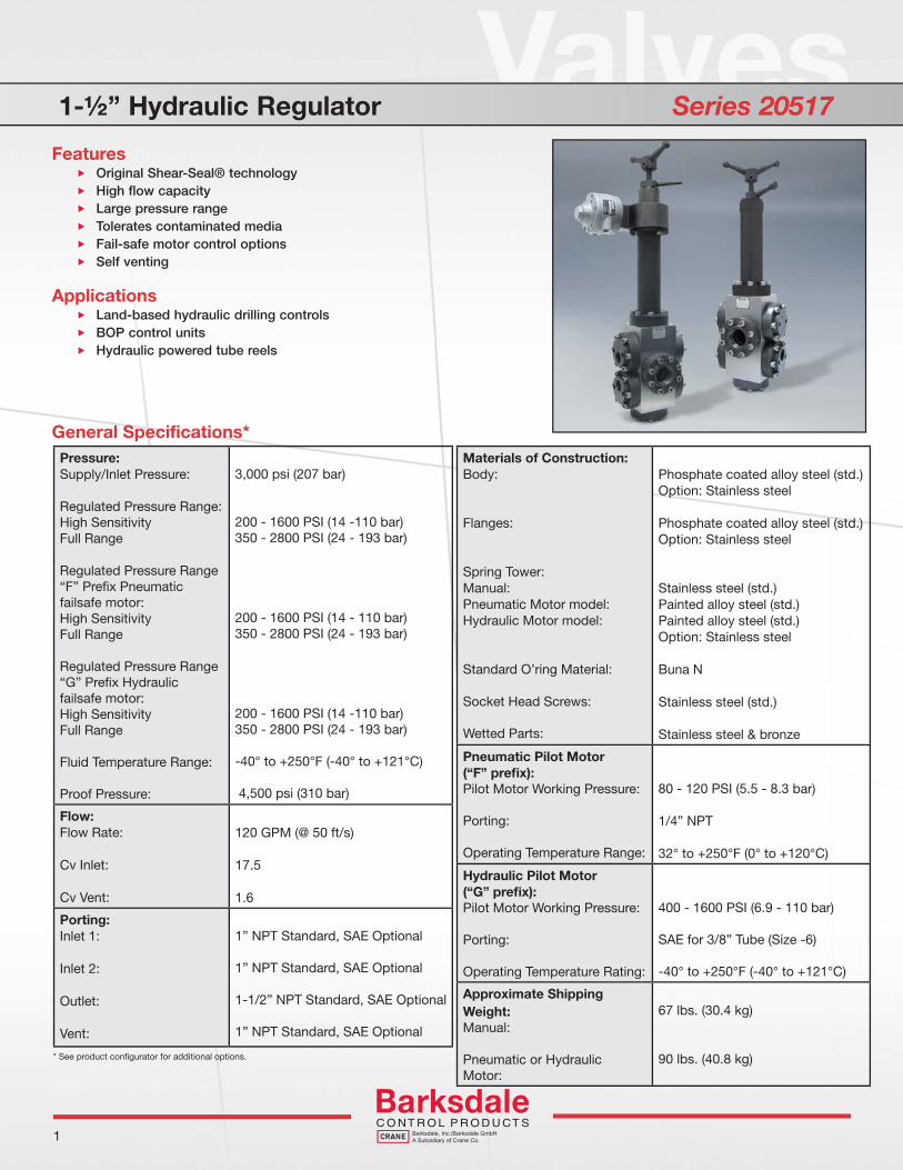
Valves1-½” Hydraulic Regulator Series 20517
General Specifications*
* See product confi gurator for additional options.
1
Features Original Shear-Seal® technology High flow capacity Large pressure range Tolerates contaminated media Fail-safe motor control options Self venting
Applications Land-based hydraulic drilling controls BOP control units Hydraulic powered tube reels
Pressure:Supply/Inlet Pressure:
Regulated Pressure Range:High SensitivityFull Range
Regulated Pressure Range“F” Prefi x Pneumatic failsafe motor:High SensitivityFull Range
Regulated Pressure Range“G” Prefi x Hydraulic failsafe motor:High SensitivityFull Range
Fluid Temperature Range:
Proof Pressure:
3,000 psi (207 bar)
200 - 1600 PSI (14 -110 bar)350 - 2800 PSI (24 - 193 bar)
200 - 1600 PSI (14 - 110 bar)350 - 2800 PSI (24 - 193 bar)
200 - 1600 PSI (14 -110 bar)350 - 2800 PSI (24 - 193 bar)
-40° to +250°F (-40° to +121°C)
4,500 psi (310 bar)
Flow:Flow Rate:
Cv Inlet:
Cv Vent:
120 GPM (@ 50 ft/s)
17.5
1.6
Porting:Inlet 1:
Inlet 2:
Outlet:
Vent:
1” NPT Standard, SAE Optional
1” NPT Standard, SAE Optional
1-1/2” NPT Standard, SAE Optional
1” NPT Standard, SAE Optional
Materials of Construction:Body:
Flanges:
Spring Tower:Manual:Pneumatic Motor model:Hydraulic Motor model:
Standard O’ring Material:
Socket Head Screws:
Wetted Parts:
Phosphate coated alloy steel (std.)Option: Stainless steel
Phosphate coated alloy steel (std.)Option: Stainless steel
Stainless steel (std.)Painted alloy steel (std.)Painted alloy steel (std.)Option: Stainless steel
Buna N
Stainless steel (std.)
Stainless steel & bronze
Pneumatic Pilot Motor (“F” prefi x):Pilot Motor Working Pressure:
Porting:
Operating Temperature Range:
80 - 120 PSI (5.5 - 8.3 bar)
1/4” NPT
32° to +250°F (0° to +120°C)
Hydraulic Pilot Motor (“G” prefi x):Pilot Motor Working Pressure:
Porting:
Operating Temperature Rating:
400 - 1600 PSI (6.9 - 110 bar)
SAE for 3/8” Tube (Size -6)
-40° to +250°F (-40° to +121°C)
Approximate Shipping Weight:Manual:
Pneumatic or Hydraulic Motor:
67 lbs. (30.4 kg)
90 lbs. (40.8 kg)
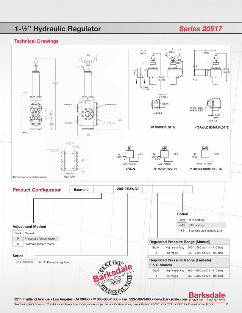
1-½” Hydraulic Regulator Series 20517
Technical Drawings
See Barksdale’s Standard Conditions of Sale • Specifications are subject to modification at any time • Bulletin #B0061-C • 02/11 • ©2011 • Printed in the U.S.A. 23211 Fruitland Avenue • Los Angeles, CA 90058 • 800-835-1060 • Fax: 323-589-3463 • www.barksdale.com
2.177
7.125
26.382(670.1)
26.382(670.1)
1.562
3.500
4.500
Example: 20517S3WQ2
Product Confi gurator
Adjustment Method
Blank Manual
F Pneumatic failsafe motor
G Hydraulic failsafe motor
Series
20517S3WQ2 1-1/2” Pressure regulator
Regulated Pressure Range (Manual)
Blank High sensitivity 200 - 1600 psi (14 - 110 bar)
-1 Full range 350 - 2800 psi (24 - 193 bar)
Regulated Pressure Range (Failsafe) F & G Models
Blank High sensitivity 200 - 1600 psi (14 - 110 bar)
-1 Full range 350 - 2800 psi (24 - 193 bar)
Option
Blank NPT porting
-MS SAE porting
-SS Stainless steel fl anges & trim
Dimensions in inches (mm)

Valves1-½” Heavy Duty Hydraulic Regulator Series 20597
General Specifications*
* See product confi gurator for additional options.
1
Features Original Shear-Seal® technology API compliant for sensitivity High flow capacity Large pressure range Tolerates contaminated media Fail-safe motor control options Self venting Surge dampening
Applications Land-based and offshore oil drilling controls BOP control units Pressure sensitive equipment
l
Pressure:Supply/Inlet Pressure:
Regulated Pressure Range:High SensitivityFull Range
Regulated Pressure Range“F” Prefi x Pneumatic failsafe motor:High SensitivityFull Range
Regulated Pressure Range“G” Prefi x Hydraulic failsafe motor:High SensitivityFull Range
Fluid Temperature Range:
Proof Pressure:
5,000 psi (345 bar)
300 - 1600 psi (21 -110 bar)500 - 3300 psi (34 - 228 bar)
300 - 1600 psi (21 - 110 bar)500 - 3000 psi (34 - 207 bar)
300 - 1600 psi (21 -110 bar)500 - 3000 psi (34 - 207 bar)
-40° to +250°F (-40° to +121°C)
7,500 psi (517 bar)
Flow:Flow Rate:
Cv Inlet:
Cv Vent:
120 GPM (@ 50 ft/s)
17.5
2.6
Porting:Inlet 1:
Inlet 2:
Outlet:
Vent:
1” NPT Standard, SAE Optional
1” NPT Standard, SAE Optional
1-1/2” NPT Standard, SAE Optional
1” NPT Standard, SAE Optional
Materials of Construction:Body:
Flanges:
Spring Tower:Manual:Pneumatic Motor model:Hydraulic Motor model:
Standard O’ring Material:
Socket Head Screws:
Wetted Parts:
Stainless steel (std.)
Phosphate coated alloy steel (std.)Option: Stainless steel
Stainless steel (std.)Painted alloy steel (std.)Painted alloy steel (std.)Option: Stainless steel
Buna N
Stainless steel (std.)
Stainless steel
Pneumatic Pilot Motor (“F” prefi x):Pilot Motor Working Pressure:
Porting:
Operating Temperature Range:
80 - 120 psi (5.5 - 8.3 bar)
1/4” NPT
32° to +250°F (0° to +120°C)
Hydraulic Pilot Motor (“G” prefi x):Pilot Motor Working Pressure:
Porting:
Operating Temperature Rating:
400 - 1600 psi (6.9 - 110 bar)
SAE for 3/8” Tube (Size -6)
-40° to +250°F (-40° to +121°C)
Approximate Shipping Weight:Manual:
Pneumatic or Hydraulic Motor:
67 lbs. (30.4 kg)
90 lbs. (40.8 kg)
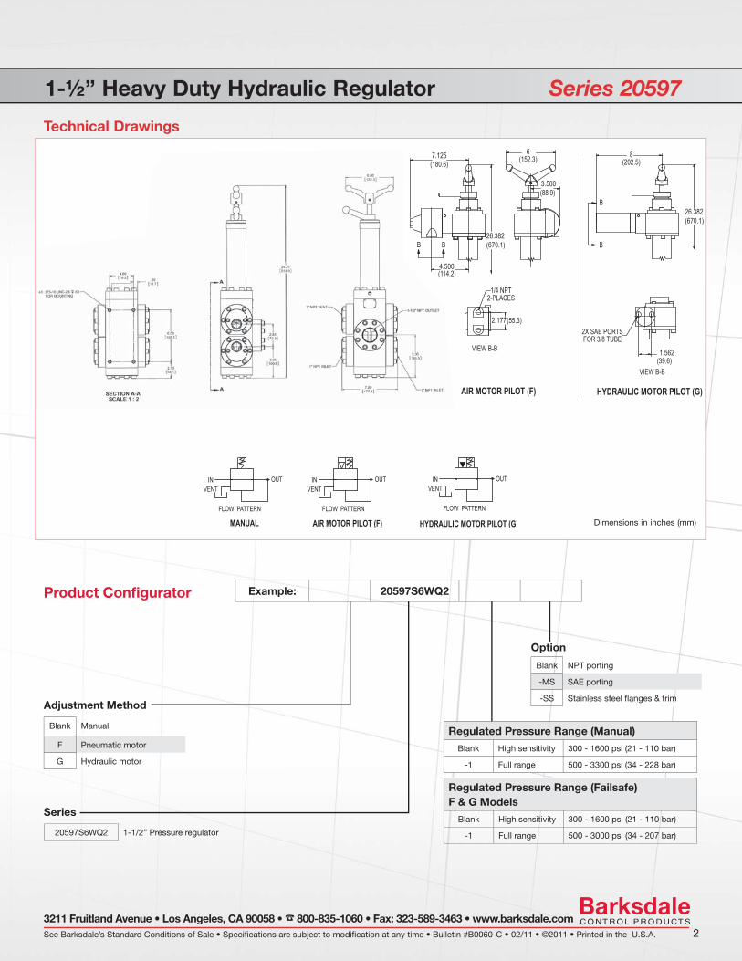
1-½” Heavy Duty Hydraulic Regulator Series 20597
Technical Drawings
See Barksdale’s Standard Conditions of Sale • Specifications are subject to modification at any time • Bulletin #B0060-C • 02/11 • ©2011 • Printed in the U.S.A. 23211 Fruitland Avenue • Los Angeles, CA 90058 • 800-835-1060 • Fax: 323-589-3463 • www.barksdale.com
Example: 20597S6WQ2
Product Confi gurator
Adjustment Method
Blank Manual
F Pneumatic motor
G Hydraulic motor
Series
20597S6WQ2 1-1/2” Pressure regulator
2.177
7.125
26.382(670.1)
26.382(670.1)
1.562
3.500
4.500
Regulated Pressure Range (Manual)
Blank High sensitivity 300 - 1600 psi (21 - 110 bar)
-1 Full range 500 - 3300 psi (34 - 228 bar)
Regulated Pressure Range (Failsafe) F & G Models
Blank High sensitivity 300 - 1600 psi (21 - 110 bar)
-1 Full range 500 - 3000 psi (34 - 207 bar)
Option
Blank NPT porting
-MS SAE porting
-SS Stainless steel fl anges & trim
Dimensions in inches (mm)
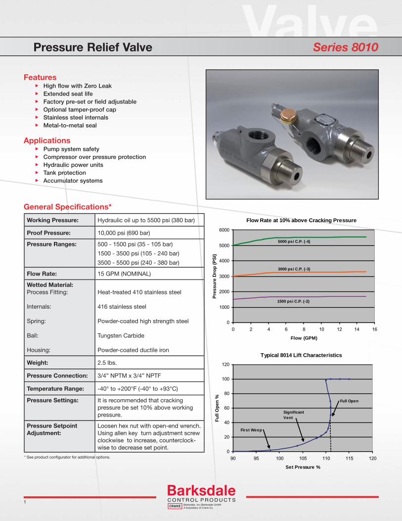
ValvePressure Relief Valve Series 8010
Features High flow with Zero Leak Extended seat life Factory pre-set or field adjustable Optional tamper-proof cap Stainless steel internals Metal-to-metal seal
Applications Pump system safety Compressor over pressure protection Hydraulic power units Tank protection Accumulator systems
Working Pressure: Hydraulic oil up to 5500 psi (380 bar)
Proof Pressure: 10,000 psi (690 bar)
Pressure Ranges: 500 - 1500 psi (35 - 105 bar)
1500 - 3500 psi (105 - 240 bar)
3500 - 5500 psi (240 - 380 bar)
Flow Rate: 15 GPM (NOMINAL)
Wetted Material:Process Fitting:
Internals:
Spring:
Ball:
Housing:
Heat-treated 410 stainless steel
416 stainless steel
Powder-coated high strength steel
Tungsten Carbide
Powder-coated ductile iron
Weight: 2.5 lbs.
Pressure Connection: 3/4” NPTM x 3/4” NPTF
Temperature Range: -40° to +200°F (-40° to +93°C)
Pressure Settings: It is recommended that cracking pressure be set 10% above working pressure.
Pressure SetpointAdjustment:
Loosen hex nut with open-end wrench. Using allen key turn adjustment screw clockwise to increase, counterclock-wise to decrease set point.
General Specifications*
* See product confi gurator for additional options.
1
Flow Rate at 10% above Cracking Pressure
3000 psi C.P. (-3)
5000 psi C.P. (-4)
1500 psi C.P. (-2)
0
1000
2000
3000
4000
5000
6000
0 2 4 6 8 10 12 14 16
Flow (GPM)
Pres
sure
Dro
p (P
SI)
Typical 8014 Lift Characteristics
0
20
40
60
80
100
120
90 95 100 105 110 115 120
Set Pressure %
Full
Ope
n %
First Weep
Significant Vent
Full Open
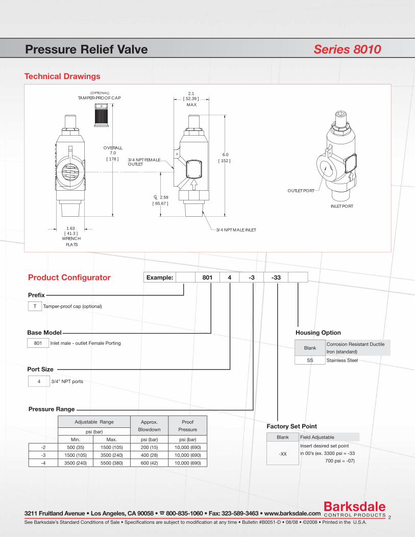
Pressure Relief Valve Series 8010
Technical Drawings
[ 65.67 ]CL 2.59
[ 178 ]
OVERALL7.0
OUTLET3/4 NPT FEMALE
3/4 NPT MALE INLET
2.1[ 52.39 ] MAX
[ 152 ] 6.0
FLATS
1.63[ 41.3 ]
WRENCH
TAMPER-PROOF CAP (OPTIONAL)
Prefix
T Tamper-proof cap (optional)
Product Configurator Example: 801 4 -3 -33
Adjustable Range Approx.
Blowdown
Proof
Pressurepsi (bar)
Min. Max. psi (bar) psi (bar)
-2 500 (35) 1500 (105) 200 (15) 10,000 (690)
-3 1500 (105) 3500 (240) 400 (28) 10,000 (690)
-4 3500 (240) 5500 (380) 600 (42) 10,000 (690)
Pressure Range
Blank Corrosion Resistant Ductile
Iron (standard)
SS Stainless Steel
Housing Option
Blank Field Adjustable
-XX
Insert desired set point
in 00’s (ex. 3300 psi = -33
700 psi = -07)
Factory Set Point
See Barksdale’s Standard Conditions of Sale • Specifications are subject to modification at any time • Bulletin #B0051-D • 08/08 • ©2008 • Printed in the U.S.A.2
3211 Fruitland Avenue • Los Angeles, CA 90058 • 800-835-1060 • Fax: 323-589-3463 • www.barksdale.com
OUTLET PORT
INLET PORT
Base Model
801 Inlet male - outlet Female Porting
Port Size
4 3/4” NPT ports

Hydraulic Relief ValveInstallation and Operating Instructions Model 8014
_________________________________________________________________________________________Barksdale, Inc. 3211 Fruitland Avenue, Los Angeles CA 90058 (800)835-1060 www.barksdale.com Bulletin No. 272233-A 12-7-06
Description: This is a hydraulic pressure relief valve having a factory set or field-adjustable set point. The valve is designed to work with hydraulic oil-based media. This valve is not intended for water or steam-based applications. Standard wetted materials include stainless steel, ductile iron, steel and Buna-N.
Caution:The recommendations below are general and it is the responsibility of the user to assure that installation and maintenance are in accordance with local requirements and ASME practices. This valve should be installed by a trained service person. A media filter should be in the system to protect the valve. Neither Barksdale nor its agents assume any liability for valves improperly used in the application or improperly installed and maintained.
Installation: Mounting: Valve shall be mounted in a vertical
position and connected in the flow direction shown by the arrow. Use wrench flat 1 5/8 inch to secure valve to pipe line.
Piping: Support with adequate piping in order to avoid excessive shock and vibration. Valve inlet is 3/4” NPT male and the outlet is 3/4” NPT female. It is recommended that a minimum of 1/2” pipe size to be used for the inlet and the outlet connection.
Ambient Temperature: -40°F to 200°F
Operating Pressure Range (PSIG):
AdjustableRangeCode
PressureRange (psi)
Tolerance± ( psi)
-1 200 - 500 50 -2 500 - 1500 150 -3 1500 - 3500 350 -4 3500 - 5500 550
Field Adjustment of Relief Pressure Set Point:
1. Tools Required: Allen key 5/16 inch Torque wrench Open end wrench 15/16 inch
2. Adjustment Procedures: Use 15/16 inch open end wrench to loosen locking nut by turning it counter clockwise (CCW). Insert Allen key to top of adjustment stud and rotate it counter clockwise (CCW) to decrease set pressure. Turn it clockwise (CW) to increase set pressure. Re-tighten anti-vibration locking nut firmly against flat valve body and torque with a torque wrench to 300 in-lb. Caution: Failure to torque locking nut to specified value can cause malfunction, failure of relief pressure, or injury.
For service or ordering information: Consult factory or authorized factory representative. Specify full catalog number (with any optional modification) and factory set point.
Adjustment Stud
~ 6 inch
2.1 inch
LockingNut
Allen Key
FlowDirection
(Torque to 300 in-lb.)
20

Barksdale GmbHDorn-Assenheimer Strasse 27 61203 Reichelsheim, Germany Phone: (49) 6035-949-0 (main offi ce)
(49) 6035-949-204 (sales)
Fax: (49) 6035-949-111/-113Email: [email protected]
Barksdale GmbHDorn-Assenheimer Strasse 27 61203 Reichelsheim, Germany Phone: (49) 6035-949-0 (main offi ce)
(49) 6035-949-204 (sales)
Fax: (49) 6035-949-111/-113Email: [email protected]
Barksdale IndiaSF- 43, Ansal Fortune ArcadeSector – 18India-201301 NoidaPhone: +91-120 25 10 522Fax: +91-120 25 10 [email protected]
Barksdale Inc.3211 Fruitland Ave.Los Angeles, CA 90058-0843U.S.A.Phone: (800) 835-1060Fax: (323) 589-3463Email: [email protected]
Global PresenceGlobal Presence