valvtechnologies, inc. electronic relief valve (erv)pressure ranges are 0 to 1000 psi (6.9 mpa),...
TRANSCRIPT
VALVTECHNOLOGIES, INC.
Electronic Relief Valve (ERV)
_________________________________________________________________
Installation, Operation & Maintenance
Supplementary Manual
To be used in conjunction with ValvTechnologies, Inc. Ball Valve Installation, Operation and Maintenance Manual
Volume 1, Revision 11 — September 2013
2
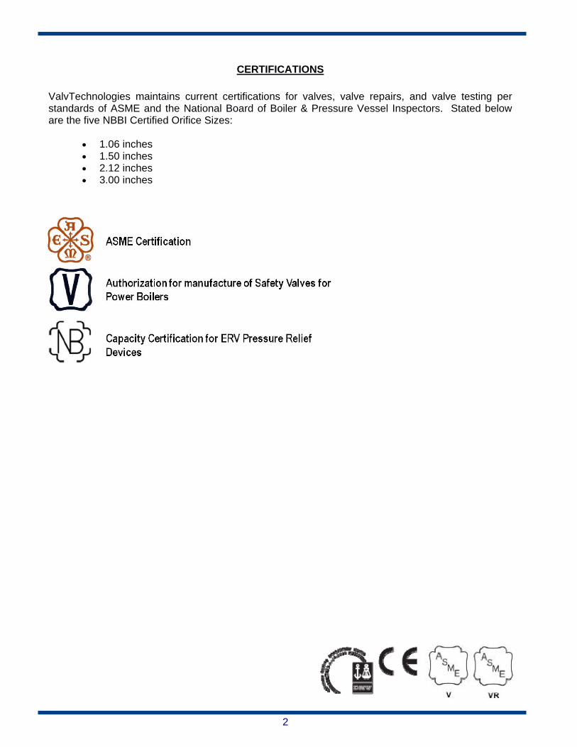
CERTIFICATIONS
ValvTechnologies maintains current certifications for valves, valve repairs, and valve testing per standards of ASME and the National Board of Boiler & Pressure Vessel Inspectors. Stated below are the five NBBI Certified Orifice Sizes:
1.06 inches 1.50 inches 2.12 inches 3.00 inches
3
TABLE OF CONTENTS
ERV System Diagram ...................................................................................................... Page 4
ERV System & Components ........................................................................................... Page 5
ERV Controls ................................................................................................................... Page 6
ERV Controls Continued ................................................................................................. Page 7
Programming / Power Supply & Control Box Specifications ........................................... Page 8
Control Box Options and Accessories ............................................................................. Page 9
Drip Pan Assembly ........................................................................................................ Page 10
Electrical Wiring ............................................................................................................. Page 11
Software ..................................................................................................................... Page 12
Software Continued ....................................................................................................... Page 13
Software Continued ....................................................................................................... Page 14
Hardware ..................................................................................................................... Page 15
Hardware Continued ...................................................................................................... Page 16
Comparison of Blowdown Options ................................................................................ Page 17
Control System Troubleshooting ................................................................................... Page 18
ERV IOM Appendix ....................................................................................................... Page 19
Contact Information ....................................................................................................... Page 20
4
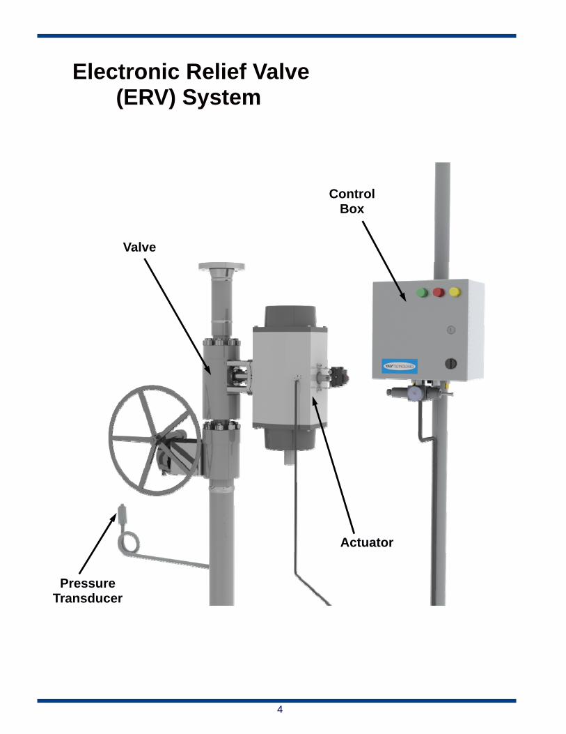
Electronic Relief Valve (ERV) System
Valve
Pressure Transducer
Actuator
Control Box
5
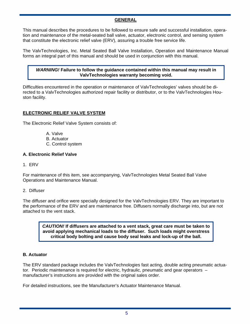
GENERAL This manual describes the procedures to be followed to ensure safe and successful installation, opera-tion and maintenance of the metal-seated ball valve, actuator, electronic control, and sensing system that constitute the electronic relief valve (ERV), assuring a trouble free service life. The ValvTechnologies, Inc. Metal Seated Ball Valve Installation, Operation and Maintenance Manual forms an integral part of this manual and should be used in conjunction with this manual. Difficulties encountered in the operation or maintenance of ValvTechnologies’ valves should be di-rected to a ValvTechnologies authorized repair facility or distributor, or to the ValvTechnologies Hou-ston facility. ELECTRONIC RELIEF VALVE SYSTEM The Electronic Relief Valve System consists of:
A. Valve B. Actuator C. Control system
A. Electronic Relief Valve 1. ERV For maintenance of this item, see accompanying, ValvTechnologies Metal Seated Ball Valve Operations and Maintenance Manual. 2. Diffuser The diffuser and orifice were specially designed for the ValvTechnologies ERV. They are important to the performance of the ERV and are maintenance free. Diffusers normally discharge into, but are not attached to the vent stack.
B. Actuator
The ERV standard package includes the ValvTechnologies fast acting, double acting pneumatic actua-tor. Periodic maintenance is required for electric, hydraulic, pneumatic and gear operators – manufacturer’s instructions are provided with the original sales order. For detailed instructions, see the Manufacturer’s Actuator Maintenance Manual.
WARNING! Failure to follow the guidance contained within this manual may result in ValvTechnologies warranty becoming void.
CAUTION! If diffusers are attached to a vent stack, great care must be taken to avoid applying mechanical loads to the diffuser. Such loads might overstress
critical body bolting and cause body seal leaks and lock-up of the ball.

6
C. ERV Controls
The ValvTechnologies ERV is supplied either with or without remote controls and display. Standard pressure ranges are 0 to 1000 psi (6.9 MPa), 1500 psi (10.3 MPa), 2000 psi (13.8 MPa), 3000 psi (20.7 MPa) and 5000 psi (34.5 MPa). Numerous lower and higher pressure ranges are available upon re-quest and considered a special order item. Standard accuracy is 0.2%. A higher accuracy range is available for all pressure range options, upon special order. Standard units operate from 115V and 230V AC or 125V DC and control AC, DC, or pneumatic actuators. Any other voltage may be accommodated by special order. Distance between remote and standard control units is determined by the manufacturer and may be virtually unlimited. ELEMENTS OF THE ERV CONTROLS A. Pressure Tap The pressure tap is critical in design, function, location and inter-relationship with the remainder of the ValvTechnologies ERV system. Although quite a rugged system, the transmitter and its electrical wires are subject to damage by abuse. The pressure tap (pig-tail) must be located at the boiler or in a large, low, or non-flowing line, such that pressure will remain at the main system pressure and read true boiler pressure under all conditions. If too close to the valve, or in a small line feeding the valve, the valve may close prematurely, causing the valve to cycle. Also see page 15 on Flowing Blowdown vs. Static Blowdown. CAUTION! The pressure tap must be oriented (as shown) such that condensate near the transmitter will flow downhill, including around the coil, until it reaches the steam line. Otherwise it is possible that the condensate will freeze and result in erroneous readings. This will prevent proper response to boiler over-pressure.
Pressure Tap Installation
7
B. Electronic Control System
The ValvTechnologies ERV electronics section consists of the following: Piesoresistive type pressure transmitter Programmable microprocessor controller Power supply to drop incoming voltage to that required for the transmitter/microprocessor
controller Circuitry to inter-connect the above Wiring NEMA 4X enclosure to enclose all above except the transmitter Suitable pressure tap to permit the transmitter to function properly Solenoid valve or motor contractor to convert electrical signal to operator actions
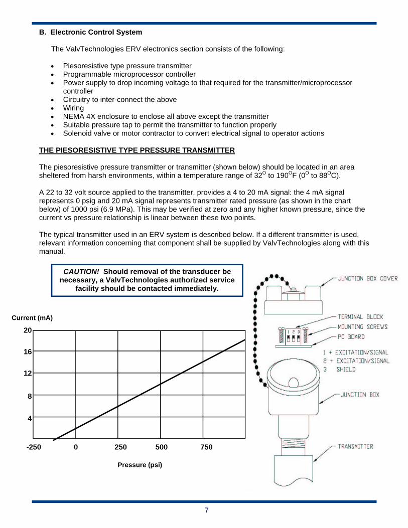
THE PIESORESISTIVE TYPE PRESSURE TRANSMITTER The piesoresistive pressure transmitter or transmitter (shown below) should be located in an area sheltered from harsh environments, within a temperature range of 32O to 190OF (0O to 88OC). A 22 to 32 volt source applied to the transmitter, provides a 4 to 20 mA signal: the 4 mA signal represents 0 psig and 20 mA signal represents transmitter rated pressure (as shown in the chart below) of 1000 psi (6.9 MPa). This may be verified at zero and any higher known pressure, since the current vs pressure relationship is linear between these two points. The typical transmitter used in an ERV system is described below. If a different transmitter is used, relevant information concerning that component shall be supplied by ValvTechnologies along with this manual.
Current (mA)
20
16
12
8
4
-250 0 250 500 750
CAUTION! Should removal of the transducer be necessary, a ValvTechnologies authorized service
facility should be contacted immediately.
Pressure (psi)
8
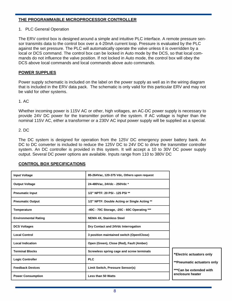
THE PROGRAMMABLE MICROPROCESSOR CONTROLLER 1. PLC General Operation The ERV control box is designed around a simple and intuitive PLC interface. A remote pressure sen-sor transmits data to the control box over a 4-20mA current loop. Pressure is evaluated by the PLC against the set pressure. The PLC will automatically operate the valve unless it is overridden by a local or DCS command. The control box can be locked in Auto mode by the DCS, so that local com-mands do not influence the valve position. If not locked in Auto mode, the control box will obey the DCS above local commands and local commands above auto commands. POWER SUPPLIES Power supply schematic is included on the label on the power supply as well as in the wiring diagram that is included in the ERV data pack. The schematic is only valid for this particular ERV and may not be valid for other systems. 1. AC Whether incoming power is 115V AC or other, high voltages, an AC-DC power supply is necessary to provide 24V DC power for the transmitter portion of the system. If AC voltage is higher than the nominal 115V AC, either a transformer or a 230V AC input power supply will be supplied as a special. 2. DC The DC system is designed for operation from the 125V DC emergency power battery bank. An DC to DC converter is included to reduce the 125V DC to 24V DC to drive the transmitter controller system. An DC controller is provided in this system. It will accept a 10 to 30V DC power supply output. Several DC power options are available. Inputs range from 110 to 380V DC CONTROL BOX SPECIFICATIONS
Input Voltage 85-264Vac, 120-375 Vdc, Others upon request
Output Voltage 24-480Vac, 24Vdc - 250Vdc *
Pneumatic Input 1/2" NPTF: 20 PSI - 125 PSI **
Pneumatic Output 1/2" NPTF: Double Acting or Single Acting **
Temperature -40C - 70C Storage, -20C - 60C Operating ***
Environmental Rating NEMA 4X, Stainless Steel
DCS Voltages Dry Contact and 24Vdc Interrogation
Local Control 3 position maintained switch (Open/Close)
Local Indication Open (Green), Close (Red), Fault (Amber)
Terminal Blocks Screwless spring cage and screw terminals
Logic Controller PLC
Feedback Devices Limit Switch, Pressure Sensor(s)
Power Consumption Less than 50 Watts
*Electric actuators only **Pneumatic actuators only ***Can be extended with enclosure heater

9
OPTIONS AND ACCESSORIES 1. Control Box Options The ERV control box can be ordered with an array of options and accessories to fit your specific ap-plication. Remote Panel: The remote panel is used to extend the functionality of the local controls to a con-
trol room or adjacent panel. Wiring instructions are provided with the remote panel. DCS Option: With this option, the control box can communicate with the plant control system. Fol-
low the wiring diagram included with the control box. HART Communication Option: This option is used to allow pass-through communication to smart
transducers and smart positioners. Specific wiring and instructions will be provided in your control box.
Battery Backup Option: Provides up to 24 hours of battery powered operation in the event of a
power failure. Redundant Pressure Monitor: This option allows you to use 2 pressure signals for redundant
monitoring in critical applications. Wiring information is provided in the control box schematic. Modbus: Standard industrial communication protocol Drip Pan: The drip pan “catches” condensation from the exhaust pipe. See page 10 for drip pan
assembly instructions.
10
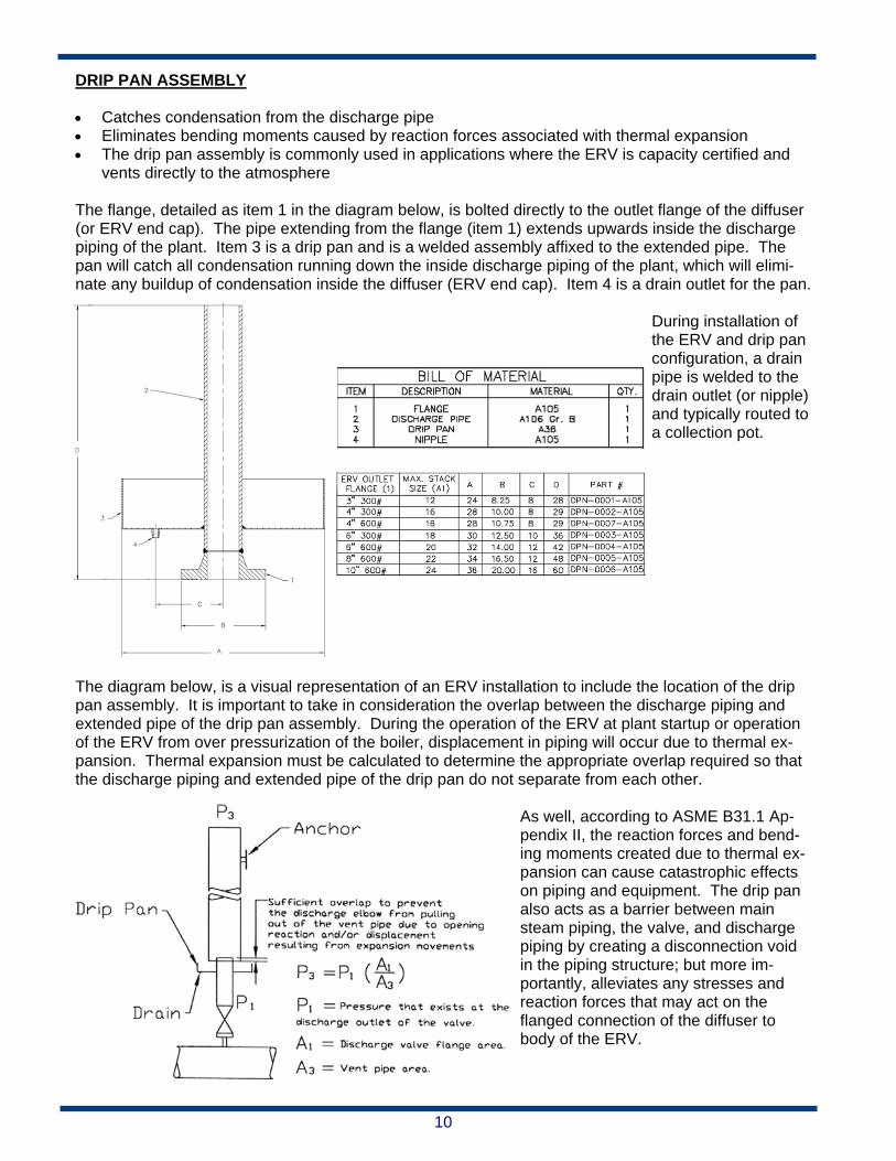
DRIP PAN ASSEMBLY Catches condensation from the discharge pipe Eliminates bending moments caused by reaction forces associated with thermal expansion The drip pan assembly is commonly used in applications where the ERV is capacity certified and
vents directly to the atmosphere The flange, detailed as item 1 in the diagram below, is bolted directly to the outlet flange of the diffuser (or ERV end cap). The pipe extending from the flange (item 1) extends upwards inside the discharge piping of the plant. Item 3 is a drip pan and is a welded assembly affixed to the extended pipe. The pan will catch all condensation running down the inside discharge piping of the plant, which will elimi-nate any buildup of condensation inside the diffuser (ERV end cap). Item 4 is a drain outlet for the pan.
During installation of the ERV and drip pan configuration, a drain pipe is welded to the drain outlet (or nipple) and typically routed to a collection pot.
The diagram below, is a visual representation of an ERV installation to include the location of the drip pan assembly. It is important to take in consideration the overlap between the discharge piping and extended pipe of the drip pan assembly. During the operation of the ERV at plant startup or operation of the ERV from over pressurization of the boiler, displacement in piping will occur due to thermal ex-pansion. Thermal expansion must be calculated to determine the appropriate overlap required so that the discharge piping and extended pipe of the drip pan do not separate from each other.
As well, according to ASME B31.1 Ap-pendix II, the reaction forces and bend-ing moments created due to thermal ex-pansion can cause catastrophic effects on piping and equipment. The drip pan also acts as a barrier between main steam piping, the valve, and discharge piping by creating a disconnection void in the piping structure; but more im-portantly, alleviates any stresses and reaction forces that may act on the flanged connection of the diffuser to body of the ERV.
11
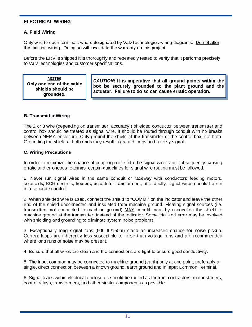
ELECTRICAL WIRING A. Field Wiring Only wire to open terminals where designated by ValvTechnologies wiring diagrams. Do not alter the existing wiring. Doing so will invalidate the warranty on this project. Before the ERV is shipped it is thoroughly and repeatedly tested to verify that it performs precisely to ValvTechnologies and customer specifications.
B. Transmitter Wiring The 2 or 3 wire (depending on transmitter “accuracy”) shielded conductor between transmitter and control box should be treated as signal wire. It should be routed through conduit with no breaks between NEMA enclosure. Only ground the shield at the transmitter or the control box, not both. Grounding the shield at both ends may result in ground loops and a noisy signal. C. Wiring Precautions In order to minimize the chance of coupling noise into the signal wires and subsequently causing erratic and erroneous readings, certain guidelines for signal wire routing must be followed. 1. Never run signal wires in the same conduit or raceway with conductors feeding motors, solenoids, SCR controls, heaters, actuators, transformers, etc. Ideally, signal wires should be run in a separate conduit. 2. When shielded wire is used, connect the shield to “COMM.” on the indicator and leave the other end of the shield unconnected and insulated from machine ground. Floating signal sources (i.e. transmitters not connected to machine ground) MAY benefit more by connecting the shield to machine ground at the transmitter, instead of the indicator. Some trial and error may be involved with shielding and grounding to eliminate system noise problems. 3. Exceptionally long signal runs (500 ft./150m) stand an increased chance for noise pickup. Current loops are inherently less susceptible to noise than voltage runs and are recommended where long runs or noise may be present. 4. Be sure that all wires are clean and the connections are tight to ensure good conductivity. 5. The input common may be connected to machine ground (earth) only at one point, preferably a single, direct connection between a known ground, earth ground and in Input Common Terminal. 6. Signal leads within electrical enclosures should be routed as far from contractors, motor starters, control relays, transformers, and other similar components as possible.
CAUTION! It is imperative that all ground points within the box be securely grounded to the plant ground and the actuator. Failure to do so can cause erratic operation.
NOTE! Only one end of the cable
shields should be grounded.
12
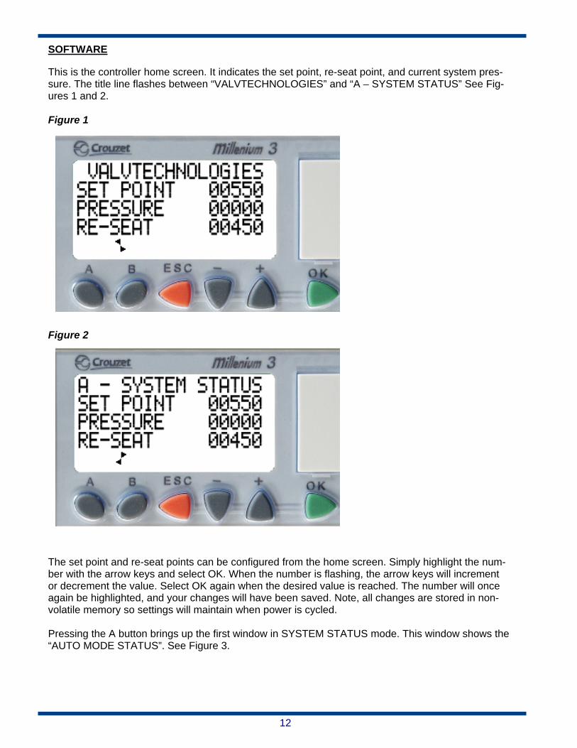
SOFTWARE This is the controller home screen. It indicates the set point, re-seat point, and current system pres-sure. The title line flashes between “VALVTECHNOLOGIES” and “A – SYSTEM STATUS” See Fig-ures 1 and 2. Figure 1
Figure 2
The set point and re-seat points can be configured from the home screen. Simply highlight the num-ber with the arrow keys and select OK. When the number is flashing, the arrow keys will increment or decrement the value. Select OK again when the desired value is reached. The number will once again be highlighted, and your changes will have been saved. Note, all changes are stored in non-volatile memory so settings will maintain when power is cycled. Pressing the A button brings up the first window in SYSTEM STATUS mode. This window shows the “AUTO MODE STATUS”. See Figure 3.
13
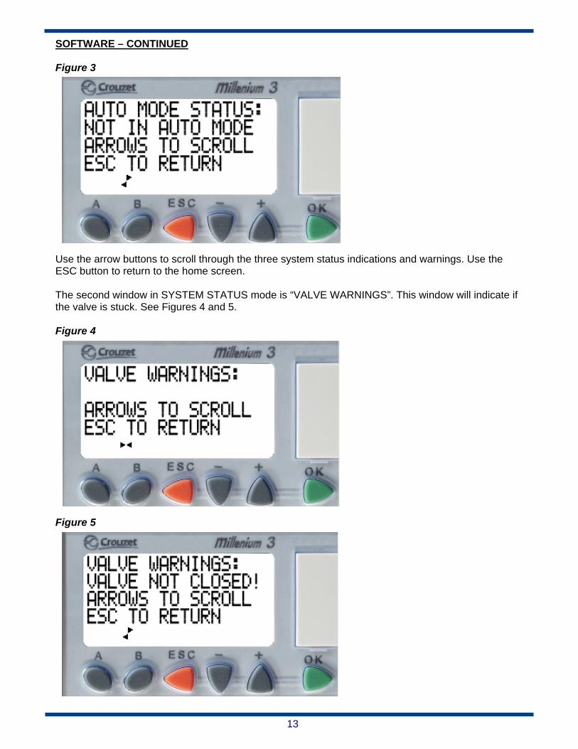
SOFTWARE – CONTINUED Figure 3
Use the arrow buttons to scroll through the three system status indications and warnings. Use the ESC button to return to the home screen. The second window in SYSTEM STATUS mode is “VALVE WARNINGS”. This window will indicate if the valve is stuck. See Figures 4 and 5. Figure 4
Figure 5

14
SOFTWARE – CONTINUED The third and final window in SYSTEM STATUS mode is “SWITCH WARNINGS”. This window will indicate if the local selector switch has been left unattended in an open or closed position. See Fig-ures 6 and 7. Figure 6
Figure 7

15
HARDWARE The ERV control box should be located in close proximity to the valve. This allows for short cable and/or pneumatic runs. Figure 8 shows a simplified block diagram of the control box’s connections and function. Figure 8
A. Electrical – Signal Level Connections must be made according to the wiring diagrams supplied with the control box. Follow these general rules for wiring the ERV control box: 1. All DCS inputs are wetted by 24VDC, supplied by the control box. 2. All DCS outputs are dry contacts and can switch 5-30VDC and 24-250VAC. a. Higher DC voltages require series resistors. b. 24VDC is available internally to use for signal inputs and outputs. 3. Limit switch feedback must be wired to the normally open limit switches. 4. 4-20mA current loop resistance is 470 ohms internally. Voltage drop will be 9.4V at full scale.
16
B. Electrical – Power Connections must be made according to the wiring diagrams supplied with the control box. 1. Follow these general rules for wiring the ERV control box:
1. Connect Control Box power through the supplied fuse block as shown on the diagram. 2. If your Control Box includes a transformer, connect power to the 1 and 4 terminals on the
primary or LV side. 3. If your ERV is electrically actuated, the Control Box will include a motor starter.
a. Connect the motor starter to the actuator as shown in the diagram. i. ONLY make connections to the right side contactor.
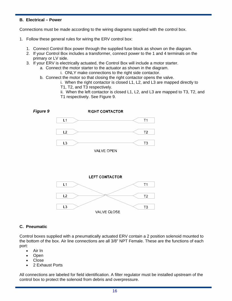
b. Connect the motor so that closing the right contactor opens the valve. i. When the right contactor is closed L1, L2, and L3 are mapped directly to T1, T2, and T3 respectively. ii. When the left contactor is closed L1, L2, and L3 are mapped to T3, T2, and T1 respectively. See Figure 9.
Figure 9 C. Pneumatic
Control boxes supplied with a pneumatically actuated ERV contain a 2 position solenoid mounted to the bottom of the box. Air line connections are all 3/8” NPT Female. These are the functions of each port:
Air In Open Close 2 Exhaust Ports
All connections are labeled for field identification. A filter regulator must be installed upstream of the control box to protect the solenoid from debris and overpressure.

17
FLOWING BLOWDOWN V.S. STATIC BLOWDOWN for ValvTechnologies, Inc. ERV
The ValvTechnologies ERV offers two options for establishing desired blowdown points. Customer option dictates the one provided. OPTION A – Flowing blowdown Pressure tap located in valve body immediately upstream from the upstream seat. Result is the requirement for a “Flowing Blowdown”, which is common to relief valves, rather than a Static Blowdown. The pressure at the sensor varies with flow rate. Blowdown Setup Procedure Options 1. Flowing Calibration Method
A) With main steam pressure at or above desired blowdown pressure, set ERV control system to manual and open the ValvTechnologies ERV. B) Monitor main steam pressure and ValvTechnologies ERV controller pressure reading. C) When main steam pressure reaches the desired blowdown value, read ValvTechnologies controller display. This is the desired blowdown value, the “low set point”. This value could be hundreds of PSI lower than the corresponding main steam pressure.
2. Operational Estimation Method
A) Estimate pressure at transmitter during full flow. B) Set blowdown to the above value (program low set point into ValvTechnologies programmable micro-processor controller; alarm 1; low set point). C) Monitor main steam pressure and ValvTechnologies transmitter/display pressure each time the ERV opens automatically. If the ERV closes prematurely or too late, note the “pressure error”. D) Estimate new optimum blowdown value. Reprogram ValvTechnologies micro-processor controller to the latest estimate “flowing blowdown value”; (Alarm 1). E) Repeat as required.
¹ Alarm 1 is the lower of 2 pressure values to which the ValvTechnologies ERV responds. It is the blowdown pressure; the low set point; the pressure at which the valve is commanded to close. Alarm 2 is the high set point; the pressure at which the valve should open. OPTION B – Static blowdown If it is desired that the ValvTechnologies transmitter read correct boiler pressure, regardless of flow rate, the ValvTechnologies pressure tap should be located as close to the boiler as practical, or in a non-flowing instrument line, or at some point where the pressure is the same as that of the boiler, regardless of the flow conditions or valve(s) position(s).
NOTE! ValvTechnologies recommends the Static Blowdown method.
18
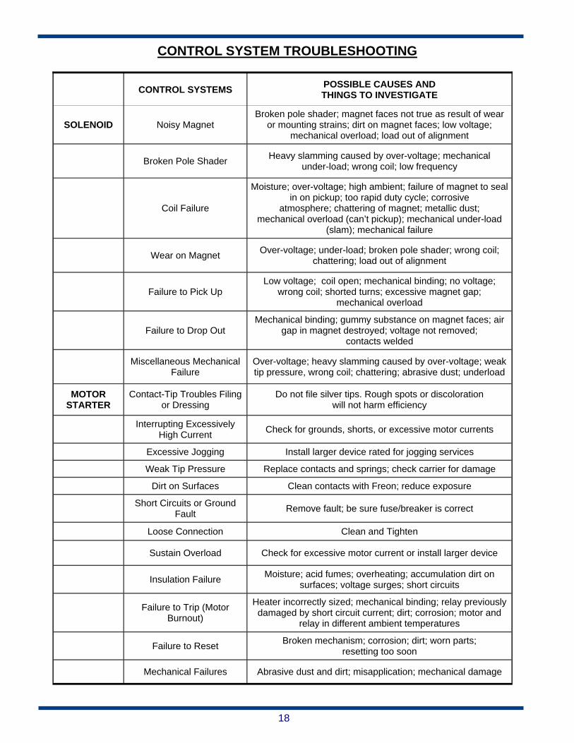
CONTROL SYSTEM TROUBLESHOOTING
CONTROL SYSTEMS POSSIBLE CAUSES AND THINGS TO INVESTIGATE
SOLENOID Noisy Magnet Broken pole shader; magnet faces not true as result of wear
or mounting strains; dirt on magnet faces; low voltage; mechanical overload; load out of alignment
Broken Pole Shader Heavy slamming caused by over-voltage; mechanical
under-load; wrong coil; low frequency
Coil Failure
Moisture; over-voltage; high ambient; failure of magnet to seal in on pickup; too rapid duty cycle; corrosive
atmosphere; chattering of magnet; metallic dust; mechanical overload (can’t pickup); mechanical under-load
(slam); mechanical failure
Wear on Magnet Over-voltage; under-load; broken pole shader; wrong coil;
chattering; load out of alignment
Failure to Pick Up Low voltage; coil open; mechanical binding; no voltage;
wrong coil; shorted turns; excessive magnet gap; mechanical overload
Failure to Drop Out Mechanical binding; gummy substance on magnet faces; air
gap in magnet destroyed; voltage not removed; contacts welded
Miscellaneous Mechanical
Failure Over-voltage; heavy slamming caused by over-voltage; weak tip pressure, wrong coil; chattering; abrasive dust; underload
MOTOR STARTER
Contact-Tip Troubles Filing or Dressing
Do not file silver tips. Rough spots or discoloration will not harm efficiency
Interrupting Excessively
High Current Check for grounds, shorts, or excessive motor currents
Excessive Jogging Install larger device rated for jogging services
Weak Tip Pressure Replace contacts and springs; check carrier for damage
Dirt on Surfaces Clean contacts with Freon; reduce exposure
Short Circuits or Ground
Fault Remove fault; be sure fuse/breaker is correct
Loose Connection Clean and Tighten
Sustain Overload Check for excessive motor current or install larger device
Insulation Failure Moisture; acid fumes; overheating; accumulation dirt on
surfaces; voltage surges; short circuits
Failure to Trip (Motor
Burnout)
Heater incorrectly sized; mechanical binding; relay previously damaged by short circuit current; dirt; corrosion; motor and
relay in different ambient temperatures
Failure to Reset Broken mechanism; corrosion; dirt; worn parts;
resetting too soon
Mechanical Failures Abrasive dust and dirt; misapplication; mechanical damage

19
ERV IOM Appendix
GENERAL DESCRIPTION
The ValvTechnologies ERV product is designed to conform to B16.34 standards. Its design spans a range of pressure classes from 150# to 4500# and bores sizes from 3/8” and up. The ERV product line is predominantly used in the Power Industry in high-temperature steam service. It’s purpose is to provide overpressure protection and regulate system pressure. It accomplishes this with an elec-tronic controller, pressure transducer, and actuator. The pressure transducer informs the controller which makes an open/close decision. The valve state and all of the controller functions are controlla-ble through DCS communication.
SPECIAL FEATURES
The ValvTechnologies ERV is the answer to the need for a zero-leakage, automated valve system. The ERV package combines ValvTechnologies’ zero-leakage isolation valve with electronic controls to monitor and regulate system pressure. Whether in a capacity-relieving function requiring the ASME V-stamp, or simply in an overpressure protection application, the ValvTechnologies ERV pro-vides reliable protection for standard safety valves in many industries. ValvTechnologies can also provide an integral isolation valve, eliminating the need for costly field welding.
OPERATION & MAINTENANCE CRITERIA
A. ERV Routine Maintenance: Periodically inspect the valve for leaks around the stem/gland and check for tightness of the bolting between the body and end cap. As well, during a plant maintenance interval, cycle the valve close/open/close and verify positioning marks to ensure a full 90 degrees of rota-tion.
B. Stem Packing Adjustment: The live-loaded stem packing system is designed to eliminate frequent adjustments. If leak-age should occur in this area the following procedures should be used:
1. Tighten each packing nut in equal amounts but only as much as is required to stop the leak.
2. If leakage persists, increase the torque in 10 percent increments until the leakage stops. Do not exceed the specified values in Table 2 on page 8 of the Ball Valve Installation and Operations Maintenance Manual by more than 20 percent.
C. Body/End cap Joint: Re-tightening of the bolting is allowed only when the line has been de-pressurized. Refer to Table 1 on page 8 of the Ball Valve Installation and Operations Maintenance Manual – Body Bolt Torque Values for maximum torque values. If leakage persists, the gasket is worn or damaged and needs replacement. Contact ValvTechnologies or your nearest authorized representative for service instructions.
Contact Address
5904 Bingle Road Houston, TX 77092 Office Phone: 713-860-0400

20
ValvTechnologies, Inc. 5904 Bingle Road
Houston, Texas 77092 U.S.A.
Phone: 713.860.0400 Fax: 713.860.0499
Email: [email protected] www.valv.com
700-ERV IOM. September 2013