vanalytics™ technical deployment guide for historical … · vanalytics™ technical deployment...
TRANSCRIPT

CONFIDENTIAL. NOT FOR DISTRIBUTION. Page 1 of 61
vAnalytics™ Technical Deployment Guide
for
Historical and Real Time Video Collaboration
Last Updated: November 15, 2016
Document Version: 3.4

CONFIDENTIAL. NOT FOR DISTRIBUTION. Page 2 of 61
THE SPECIFICATIONS AND INFORMATION REGARDING THE PRODUCTS IN THIS DOCUMENT ARE SUBJECT TO CHANGE WITHOUT NOTICE. ALL STATEMENTS, INFORMATION, AND RECOMMENDATIONS IN THIS DOCUMENT ARE BELIEVED TO BE ACCURATE BUT ARE PRESENTED WITHOUT WARRANTY OF ANY KIND, EXPRESS OR IMPLIED. USERS MUST TAKE FULL RESPONSIBILITY FOR THEIR APPLICATION OF ANY PRODUCTS. NOTWITHSTANDING ANY OTHER WARRANTY HEREIN, ALL DOCUMENT FILES AND SOFTWARE ARE PROVIDED “AS IS” WITH ALL FAULTS. VYOPTA DISCLAIMS ALL WARRANTIES, EXPRESSED OR IMPLIED, INCLUDING, WITHOUT LIMITATION, THOSE OF MERCHANTABILITY, FITNESS FOR A PARTICULAR PURPOSE AND NONINFRINGEMENT OR ARISING FROM A COURSE OF DEALING, USAGE, OR TRADE PRACTICE. IN NO EVENT SHALL VYOPTA BE LIABLE FOR ANY INDIRECT, SPECIAL, CONSEQUENTIAL, OR INCIDENTAL DAMAGES, INCLUDING, WITHOUT LIMITATION, LOST PROFITS OR LOSS OR DAMAGE TO DATA ARISING OUT OF THE USE OR INABILITY TO USE THIS DOCUMENT, EVEN IF VYOPTA HAS BEEN ADVISED OF THE POSSIBILITY OF SUCH DAMAGES. Other company and product names mentioned herein may be trademarks of their respective companies. Mention of third-party products is for informational purposes only and constitutes neither an endorsement nor a recommendation. Vyopta assumes no responsibility with regard to the performance or use of these products. All understandings, agreements, or warranties, if any, take place directly between the vendors and the prospective users. Every effort has been made to ensure that the information in this document is accurate. Vyopta is not responsible for printing or clerical errors. Copyright © 2016 Vyopta Incorporated. All rights reserved. Vyopta® is a registered trademark of Vyopta Incorporated. Reg. USPTO.

CONFIDENTIAL. NOT FOR DISTRIBUTION. Page 3 of 61
1 Table of Contents
1 Table of Contents ....................................................................................................................................... 3
2 Getting Started - Preparing Your Environment ............................................................................................. 6
2.1 Overview.......................................................................................................................................................................... 6
2.2 Sign Up for a Vyopta Applications Management Portal User Account ........................................................................... 6
2.3 Obtain Administrator Access for your User Account ...................................................................................................... 6
2.4 Configure a vAnalytics™ Service Account ....................................................................................................................... 7
2.5 Prepare a vAnalytics™ Data Collector ............................................................................................................................. 8
2.6 Test Connection to the Vyopta Cloud ............................................................................................................................. 9
2.7 Download and Install the vAnalytics™ Data Collector .................................................................................................... 9
2.8 Complete vAnalytics™ Configuration Utility Setup ....................................................................................................... 10
2.9 Operational Prerequisites ............................................................................................................................................. 11
2.10 Coverage and Compatibility .......................................................................................................................................... 11
3 Cisco VCS Control (VCS-C) & VCS Expressway (VCS-E) .................................................................................. 12
3.1 Set up a Service Account for Cisco VCS Control (VCS-C) & Expressway (VCS-E) ........................................................... 12
3.2 Add VCS-C/VCS-E ........................................................................................................................................................... 13
3.3 Cisco Video Communications Server Control (VCS-C) & Expressway (VCS-E) Reference Table ................................... 14
4 Cisco Telepresence Multipoint Control Unit (MCU), Telepresence Server (TPS), or
Telepresence Integrated Services Digital Network (ISDN) Gateway .............................................................. 15
4.1 Set up a Service Account for Cisco Multipoint Control Unit (MCU), Telepresence Server (TPS), or
Integrated Services Digital Network (ISDN) Gateway ................................................................................................... 15
4.2 Enable CDR Permanent Storage on Cisco Codian (MCU) & ISDN Gateway .................................................................. 17
4.3 Add MCU, TP Server, or ISDN Gateway ......................................................................................................................... 17
4.4 Cisco TelePresence Multipoint Control Unit (MCU) Reference Table .......................................................................... 19
4.5 Cisco TelePresence Server (TPS) Reference Table ........................................................................................................ 19
4.6 Cisco TelePresence ISDN Gateway Reference Table ..................................................................................................... 19

CONFIDENTIAL. NOT FOR DISTRIBUTION. Page 4 of 61
5 Cisco Telepresence Management Suite (TMS) SQL Server Database ............................................................. 20
5.1 Set up a Service Account for Cisco Telepresence Management Suite (TMS) SQL Server Database ............................. 20
5.2 Add a TMS and TMS Provisioning Extension Connector ............................................................................................... 21
5.3 Cisco TelePresence Management Suite (TMS) Reference Table .................................................................................. 22
6 Cisco Unified Communications Manager (CUCM) ....................................................................................... 23
6.1 Enable the AXL API User Role for Cisco Unified Communications Manager (CUCM) ................................................... 23
6.2 Set up a Service Account for CUCM .............................................................................................................................. 24
6.3 Add CUCM Connectors for the Publisher ...................................................................................................................... 28
6.4 Cisco Unified Communications Manager (CUCM) Reference Table ............................................................................. 29
7 Cisco Meeting Server (CMS; formerly Acano Server) ................................................................................... 30
7.1 Set up a Service Account for Cisco Meeting Server (CMS)............................................................................................ 30
7.2 Add a CMS Connector ................................................................................................................................................... 31
7.3 Cisco Meeting Server (CMS) Reference Table ............................................................................................................... 33
8 Cisco WebEx ............................................................................................................................................ 34
8.1 Set up a Service Account for Cisco WebEx .................................................................................................................... 34
8.2 Add a WebEx Connector................................................................................................................................................ 35
8.3 Cisco WebEx (Cloud only) Reference Table................................................................................................................... 36
9 Pexip Infinity .............................................................................................................................................37
9.1 Validate the Service Account for Pexip Infinity ............................................................................................................. 37
9.2 Add a Pexip Connector .................................................................................................................................................. 38
9.3 Pexip Infinity Reference Table ....................................................................................................................................... 39
10 Microsoft Lync Server ............................................................................................................................... 40
10.1 Set up a Service Account for Microsoft Lync Server ..................................................................................................... 40
10.2 Add a Microsoft Lync Server Connector........................................................................................................................ 42
10.3 Microsoft Skype for Business/Lync Reference Table .................................................................................................... 43

CONFIDENTIAL. NOT FOR DISTRIBUTION. Page 5 of 61
11 Polycom RealPresence Distributed Media Application (DMA) ...................................................................... 44
11.1 Verify API Licensing and Set up Service Account for Polycom RealPresence Distributed Media Application (DMA) .. 44
11.2 Add a Polycom DMA Connector .................................................................................................................................... 45
11.3 Polycom RealPresence Distributed Media Application (DMA) Reference Table .......................................................... 47
12 Polycom RealPresence Collaboration server (RMX) ..................................................................................... 48
12.1 Set up a Service Account for Polycom RealPresence Collaboration server (RMX) ....................................................... 48
12.2 Add a Polycom RMX Connector .................................................................................................................................... 49
12.3 Polycom RealPresence Collaboration server (RMX) Reference Table .......................................................................... 50
13 Polycom RealPresence Resource Manager (RPRM) ..................................................................................... 51
13.1 Verify API Licensing and Set up a Service Account for Polycom RealPresence Resource Manager (RPRM) ................ 51
13.2 Add a Polycom RPRM Connector .................................................................................................................................. 52
13.3 Polycom RealPresence Resource Manager (RPRM) Reference Table........................................................................... 53
14 Vidyo Management Portal ........................................................................................................................ 54
14.1 Enabling CDR Access in the Vidyo Management Portal ................................................................................................ 54
14.2 Add a Vidyo Management Portal Connector ................................................................................................................ 55
14.3 Vidyo Management Portal Reference Table ................................................................................................................. 56
15 Saving the vAnalytics™ Configuration and Starting the vAnalytics™ Service .................................................. 57
15.1 Saving the vAnalytics™ Configuration and Starting the vAnalytics™ Service ............................................................... 57
15.2 Troubleshooting a Failed Connection ........................................................................................................................... 58
16 SolarWinds Integration ............................................................................................................................. 59
16.1 Requirements ................................................................................................................................................................ 59
16.2 Configuration ................................................................................................................................................................. 60
16.3 Verification .................................................................................................................................................................... 61

CONFIDENTIAL. NOT FOR DISTRIBUTION. Page 6 of 61
2 Getting Started - Preparing Your Environment
2.1 Overview
Vyopta’s vAnalytics™ application provides an immersive view into your organization’s investment in
video & unified communications infrastructure, with insights on utilization, capacity and adoption as
well as real-time monitoring capabilities. This guide is designed to help you prepare your environment
for the installation of Vyopta’s vAnalytics. Please follow the subsequent steps in order to completely and
properly install Vyopta’s vAnalytics.
2.2 Sign Up for a Vyopta Applications Management Portal User Account
To get started, you will need to create a user account in Vyopta’s Applications Management Portal. To
log into Vyopta’s Applications Management Portal:
1. Open a web browser and navigate to the Vyopta website (www.vyopta.com). 2. Select login, in the upper right corner of the screen. 3. Select Create an Account and enter your company email address. 4. You will receive an email containing a link to sign up for a Vyopta Applications Management
Portal user account. Fill out the form linked in the email to set up your user account.
Note: your email must be tied to the domain of your organization.
2.3 Obtain Administrator Access for your User Account
Your user account must have Administrator privileges for you to complete the remainder of the steps for
the vAnalytics deployment. If you are the first account to register for your organization, you will
automatically have Administrator privileges. If you only have access to the Profile menu, you do not
have Administrator privileges and will need to request Administrator access. To request Administrator
access, please contact your organization’s current administrators. The list of administrators for your
organization can be found on the Organization Profile page.

CONFIDENTIAL. NOT FOR DISTRIBUTION. Page 7 of 61
2.4 Configure a vAnalytics™ Service Account
Once you have successfully configured your user account and obtained Administrator privileges, you are
ready to provision a service account for vAnalytics. The service account is used to manage the vAnalytics
Data Collector deployed within your environment.
To create the service account, log into the Applications Management Portal and navigate to the Admin >
Users Page. Select the icon in the upper-right corner of the screen to add a new user. Fill out the
information for the vAnalytics service account (Figure below); be sure to give the service account
administrator privileges.
Figure 2-1: vAnalytics Service Account Setup
The vAnalytics service account does not require an active email address for the username or email
address fields, but requires your domain be included in the email (i.e.
vAnalytics_svc@<yourdomain>.com).
When you have entered the information for the vAnalytics service account, click the save button.

CONFIDENTIAL. NOT FOR DISTRIBUTION. Page 8 of 61
2.5 Prepare a vAnalytics™ Data Collector
A server must be provisioned on which the vAnalytics Data Collector will be installed and configured.
The Data Collector is used to communicate with your video infrastructure in your internal, and in some
cases, external environment. The server can be either a virtual or physical appliance. The server will
need network access to your video infrastructure and will always be running.
Please see the table below for the recommended specifications:
CPU Dual 2.4GHz or Higher
Memory 8GB RAM Recommended
Disk Space 160 GB OS and Data
Network Single NIC
Operating System Windows Server 2012 or 2008 R2
System Software .NET Framework Version 4.5 (Tested to v4.6)

CONFIDENTIAL. NOT FOR DISTRIBUTION. Page 9 of 61
2.6 Test Connection to the Vyopta Cloud
It is important to test the connection to Vyopta’s Cloud on the VM or server provisioned for vAnalytics™.
To test the connection to the Vyopta Cloud, the Administrator must ensure https connectivity to the
following Vyopta Cloud Servers: apps.vyopta.com, rtadr.vyotpa.com, adr.vyopta.com and
vanalytics.vyopta.com.
Please perform the following tests from Remote Desktop (RDP) on the vAnalytics Virtual Machine:
1. Open a web browser and navigate to the Vyopta website (www.vyopta.com) and select login in the upper right corner of the screen.
2. Ensure you are directed to Vyopta’s Applications Management Portal (apps.vyopta.com). 3. Navigate to rtadr.vyopta.com and confirm that you see the message similar to below. 4. Navigate to adr.vyopta.com and confirm that you see the message similar to below. 5. Finally, navigate to vanalytics.vyopta.com and confirm that you see the message similar to
below.
Figure 2-2: Vyopta vAnalytics Test Connection Page
2.7 Download and Install the vAnalytics™ Data Collector
To download and install the vAnalytics Data Collector, please do the following:
1. Download the vAnalytics Data Collector Installer (EXE) from the following URL: http://vapps.vyopta.com/client/software/vAnalyticsDataCollector.exe
2. Once the application has downloaded, open and run the installer on the vAnalytics Data Collector provisioned in your environment (refer to step 2.6 in this guide).
3. Follow the installer’s instructions to complete the simple installation process.

CONFIDENTIAL. NOT FOR DISTRIBUTION. Page 10 of 61
2.8 Complete vAnalytics™ Configuration Utility Setup
Once the vAnalytics Configuration Utility is installed, you are almost ready to begin adding your
infrastructure to the Data Collector. To complete the setup:
1. Go to Start > All Programs > Vyopta > vAnalytics and open the vAnalytics System Configuration Utility.
2. Once the vAnalytics Data Collector application has opened, click on “Get Started” to begin. 3. When ready, click the Proceed button and enter the previously created service account
vAnalytics_svc@<yourdomain>.com and your password. 4. Click “Next” to test your connection to the Vyopta Cloud.
Figure 2-3: vAnalytics Configuration Utility
5. Once the connection is validated click “Next” and the utility will then bring you to the Add Infrastructure page. Click on “Add Infrastructure” to add a component of your video infrastructure.
Note: If you forget your organization’s vAnalytics service account username or password, you can log
into Vyopta’s Applications Management Portal at apps.vyopta.com to view the name of the account
and/or to change the password.

CONFIDENTIAL. NOT FOR DISTRIBUTION. Page 11 of 61
2.9 Operational Prerequisites
The following prerequisites must be met to successfully configure and operate Vyopta’s vAnalytics™:
1. Network communication over specific ports between the vAnalytics Data Collector and all video infrastructure components within your video environment.
2. Service accounts with sufficient privileges (typically read-only administrative access) on each component of your video infrastructure.
The remainder of this guide is devoted to taking you through the steps necessary to configure vAnalytics for each of the supported video infrastructure components, detailed in Section 2.10 – Coverage and Compatibility.
2.10 Coverage and Compatibility
The following video infrastructure components are compatible with vAnalytics™:
Cisco Video Communications Server (VCS) Control and Expressway Cisco Multipoint Control Unit (MCU) Cisco Telepresence Server Cisco Telepresence ISDN Gateways Cisco Telepresence Management Suite & Provisioning Extension Cisco Unified Communications Manager Cisco WebEx Cisco Meeting Server (CMS; formerly Acano Server) Microsoft Lync Server Pexip Management Node Polycom DMA with API License Polycom RMX Polycom RPRM with API License Vidyo Management Portal

CONFIDENTIAL. NOT FOR DISTRIBUTION. Page 12 of 61
3 Cisco VCS Control (VCS-C) & VCS Expressway (VCS-E)
3.1 Set up a Service Account for Cisco VCS Control (VCS-C) & Expressway (VCS-E)
To create a service account on the device, perform the following:
1. Log into the VCS with the proper administrator account. 2. Navigate to the Users > Administrator Accounts tab.
Figure 3-1: Administrator Accounts Tab
3. Select New. 4. Enter the following name for the service account: vyopt a_svc 5. Set the Access level to Read-only. 6. Enter the service account password and confirm this password. 7. Set Web Access and API Access to Yes and State to Enabled. 8. Click Save.
Figure 3-2: New Service Account
The Vyopta Service account is now added to the device. The service account must be added to each VCS
Control and Expressway within the video environment.
Note: VCS Active Directory (AD) accounts are not supported. The account must be a local administrator.

CONFIDENTIAL. NOT FOR DISTRIBUTION. Page 13 of 61
3.2 Add VCS-C/VCS-E
To add a Cisco VCS-C or VCS-E requires the following:
Access to the FQDN/IP address of the video device from the vAnalytics Data Collector Previously created user service account credentials on each video device
Note: If you have multiple VCS-C or VCS-E devices you must add a connector for each individual device
including all peers and slaves.
Please follow the instructions below to add each video infrastructure device:
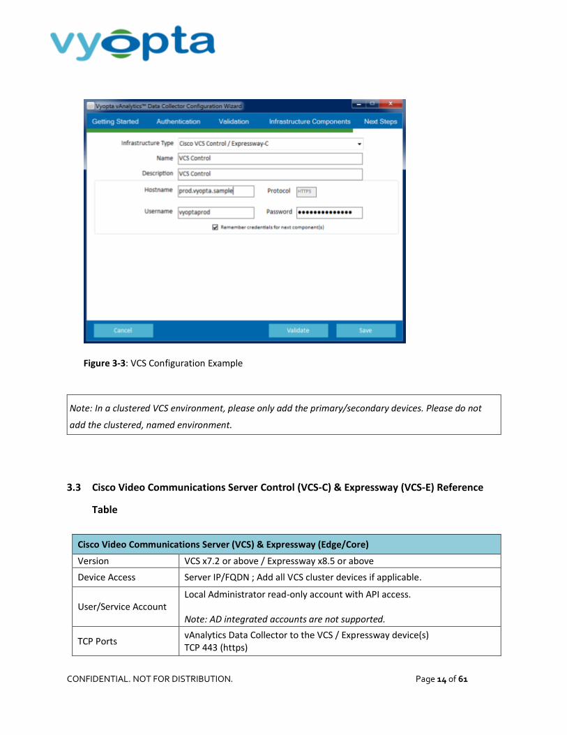
1. Select the correct VCS type in the Infrastructure Type drop-down menu. 2. Enter the infrastructure name. This will be the name displayed for the video device in the
Configuration Utility and within Vyopta’s Applications Management Portal.
Note: We recommend using hostname rather than IP as IP addresses are subject to change. It is also
helpful to name the infrastructure in a 'friendly' or easily understood way.
1. Enter the description of the video device. This can include the device type, location, and other unique identifiers.
2. Enter the infrastructure hostname or IP address. 3. Enter the username and password created on the video device. 4. Click Validate to ensure that the vAnalytics application can connect to the video device. 5. If the connection to the video component succeeded, click the Save button.
CONFIDENTIAL. NOT FOR DISTRIBUTION. Page 14 of 61
Figure 3-3: VCS Configuration Example
Note: In a clustered VCS environment, please only add the primary/secondary devices. Please do not
add the clustered, named environment.
3.3 Cisco Video Communications Server Control (VCS-C) & Expressway (VCS-E) Reference
Table
Cisco Video Communications Server (VCS) & Expressway (Edge/Core)
Version VCS x7.2 or above / Expressway x8.5 or above
Device Access Server IP/FQDN ; Add all VCS cluster devices if applicable.
User/Service Account Local Administrator read-only account with API access. Note: AD integrated accounts are not supported.
TCP Ports vAnalytics Data Collector to the VCS / Expressway device(s) TCP 443 (https)

CONFIDENTIAL. NOT FOR DISTRIBUTION. Page 15 of 61
4 Cisco Telepresence Multipoint Control Unit (MCU), Telepresence Server (TPS), or Telepresence Integrated Services Digital Network (ISDN) Gateway
4.1 Set up a Service Account for Cisco Multipoint Control Unit (MCU), Telepresence Server
(TPS), or Integrated Services Digital Network (ISDN) Gateway
The instructions below are separated by device type. Please follow the relevant instructions to create a
service account on the component being added:
Note: MCU supervisor blades and slave blades in an MCU cluster do not need to be added.
For Cisco Multipoint Control Units (Codian MCUs) or ISDN Gateways:
1. Log into the infrastructure with any Administrator account. 2. Click on the User tab. 3. Select Add New User. 4. Enter the User ID as vyopt a_svc and Account Name as vyopt a_svc 5. Enter and Re-enter the password. 6. Uncheck the box for Force user to change password on next login. 7. Set the Privilege level to administrator. 8. Leave the E.164 phone number blank. 9. When finished, add the User.
Figure 4-1: Add MCU User Service Account

CONFIDENTIAL. NOT FOR DISTRIBUTION. Page 16 of 61
For Cisco TelePresence Servers (TPS) perform the following:
1. Log into the infrastructure with any Administrator account. 2. Click on the User tab. 3. Select Add New User. 4. Enter in the User ID as vyopt a_svc and Account Name as vyopt a_svc . 5. Enter and re-enter the password. 6. Set the privilege level to API access. 7. When finished, select Add User.
Figure 4-2: Add TPS User Service Account
Note: Please ensure that http is enabled for your TP Server. If it is not enabled, call quality will not be
reported for TP Server in Real Time/Historical.
Figure 4-3: HTTP can be enabled within your TP Server under Network→ Services→ HTTP

CONFIDENTIAL. NOT FOR DISTRIBUTION. Page 17 of 61
4.2 Enable CDR Permanent Storage on Cisco Codian (MCU) & ISDN Gateway
In order to maximize the number of call detail records stored on the MCU and ISDN Gateway you must
enable CDR permanent storage by performing the following:
1. Log into the device with an administrator account. 2. Navigate to Logs -> CDR logs. 3. Click on the Enable CDR permanent storage button.
Figure 4-4: Click to enable CDR permanent storage
4.3 Add MCU, TP Server, or ISDN Gateway
To add a Cisco MCU, Telepresence Server, or ISDN Gateway requires the following:
Access to the FQDN/ IP address of the video device from the vAnalytics Data Collector Previously created user service account credentials on each video device
Note: If you have multiple MCUs, TPS peers, or clusters you must add a connector for each individual
device or blade. Do not add slave MCUs as all information is obtained from the Master MCU.

CONFIDENTIAL. NOT FOR DISTRIBUTION. Page 18 of 61
Please follow the instructions below to add each video infrastructure device:
1. Select the correct device type in the Infrastructure Type drop-down menu. 2. Enter the infrastructure name. This will be the name displayed for the video device in the
Configuration Utility and within Vyopta’s Applications Management Portal.
Note: We recommend using hostname rather than IP as IP addresses are subject to change. It is also
helpful to name the infrastructure in a 'friendly' or easily understood way.
3. Enter the description of the video device. This can include the device type, location, and other unique identifiers.
4. Enter the infrastructure hostname or IP address. 5. Enter the username and password created on the video device. 6. Click Validate to ensure that the vAnalytics application can connect to the video device. 7. If the connection to the video component succeeded, click the Save button.
Figure 4-5: MCU Configuration Example

CONFIDENTIAL. NOT FOR DISTRIBUTION. Page 19 of 61
4.4 Cisco TelePresence Multipoint Control Unit (MCU) Reference Table
Cisco TelePresence MCU
Version MCU version 4.1 or above
Device Access Server IP/FQDN
User/Service Account Local account with Administrator privileges
TCP Ports
vAnalytics Data Collector to the MCU device(s) TCP 443 (https) If MCU is in a cluster only the Master needs to be added
4.5 Cisco TelePresence Server (TPS) Reference Table
Cisco TelePresence Server (TPS)
Version TPS 3.1 or above
Device Access Server IP/FQDN
User/Service Account Local account with API Access (or Administrator privileges)
TCP Ports vAnalytics Data Collector to the TPS device(s) TCP 443 (https)
4.6 Cisco TelePresence ISDN Gateway Reference Table
Cisco TelePresence ISDN Gateway
Version Version 2.1 or above
Device Access Server IP/FQDN
User/Service Account Local account with Administrator privileges
TCP Ports vAnalytics Data Collector to the ISDN device(s) TCP 443 (https)

CONFIDENTIAL. NOT FOR DISTRIBUTION. Page 20 of 61
5 Cisco Telepresence Management Suite (TMS) SQL Server Database
5.1 Set up a Service Account for Cisco Telepresence Management Suite (TMS) SQL Server
Database
The service account required will be added to the appliance’s SQL Database with read-only privileges.
You must determine where the appliance’s SQL Server Database is located in your environment;
whether it is on the TMS appliance or located on a separate SQL server. Once this has been identified,
you will require an Administrator account to the server to add the vAnalytics service account. This may
require the assistance of a SQL Server Administrator in your organization to provide server access or to
add the account manually.
For all instances where the TMS/TMSPE SQL databases are hosted on a separate SQL Server please
consult with your organization’s SQL Server DBA to create the required database read-only account.
There are two ways to identify where your TMS & TMSPPE databases are located:
1. RDP to the TMS server as an administrator and run the ‘TMS Tools’ application configuration utility from Start > Programs > Cisco TelePresence Management Suite. Please note that this is the recommended option as it highlights the connection port.
2. Log in to the TMS Web UI as an administrator and navigate to Administrative Tools > TMS Server Maintenance. Click on ‘Database Files and Size Info’ to view the database server in use. If the database server is ‘(local)\SQLTMS’ then your database resides on the actual TMS server. Your database could also use the name of the actual server, e.g. ‘TMSPROD\SQLTMS’. If the server name matches your TMS server then your database resides on the TMS server.
The read-only database account should be titled vyopta_svc which has the ‘db_datareader’ and ‘public’
roles as well as access to the ‘tmsng’ and ‘tmspe’ databases. For SQL databases residing on the TMS
server (atypical), please contact [email protected] for assistance with the TMS Preparation Installer.
Note: You will need to make sure that you obtain the assigned password and also the appropriate
TCP/IP port for database access. The default for this is 1433 but other ports can be configured.
CONFIDENTIAL. NOT FOR DISTRIBUTION. Page 21 of 61
5.2 Add a TMS and TMS Provisioning Extension Connector
To add a connector for Telepresence Management Suite (TMS) and/or Telepresence Management Suite
Provisioning Extension (TMSPE) you will need to prepare by completing the following prerequisites:
Confirm access to the FQDN/IP address of the server hosting the SQL Database from the vAnalytics Data Collector.
Obtain credentials for the Microsoft SQL Server Database Read-only Account. Identify whether a static or dynamic SQL port is used. (If dynamic, please identify and record the
dynamic port value within Microsoft SQL Configuration Manager.) Verify that TCP/IP is enabled for the SQL Server within SQL Configuration Manager.
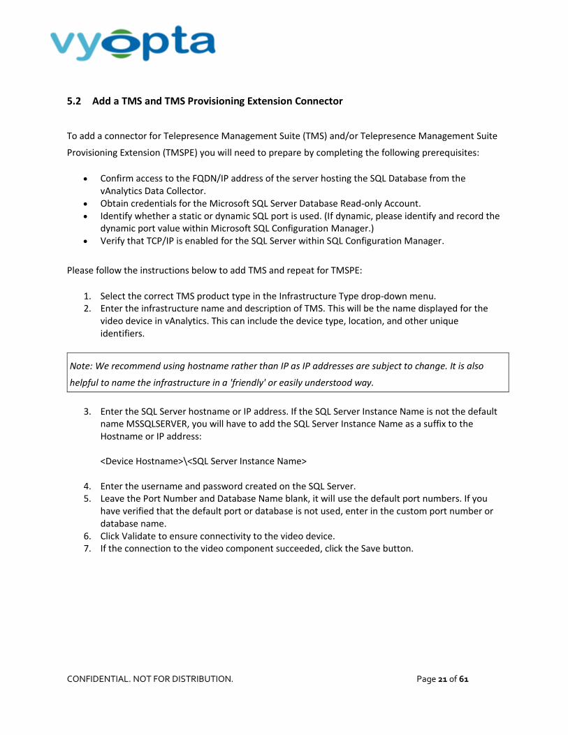
Please follow the instructions below to add TMS and repeat for TMSPE:
1. Select the correct TMS product type in the Infrastructure Type drop-down menu. 2. Enter the infrastructure name and description of TMS. This will be the name displayed for the
video device in vAnalytics. This can include the device type, location, and other unique identifiers.
Note: We recommend using hostname rather than IP as IP addresses are subject to change. It is also
helpful to name the infrastructure in a 'friendly' or easily understood way.
3. Enter the SQL Server hostname or IP address. If the SQL Server Instance Name is not the default name MSSQLSERVER, you will have to add the SQL Server Instance Name as a suffix to the Hostname or IP address: <Device Hostname>\<SQL Server Instance Name>
4. Enter the username and password created on the SQL Server. 5. Leave the Port Number and Database Name blank, it will use the default port numbers. If you
have verified that the default port or database is not used, enter in the custom port number or database name.
6. Click Validate to ensure connectivity to the video device. 7. If the connection to the video component succeeded, click the Save button.
CONFIDENTIAL. NOT FOR DISTRIBUTION. Page 22 of 61
Figure 5-1: TMS Configuration Example
Note: You must repeat the procedure above to add the TMSPE database.
5.3 Cisco TelePresence Management Suite (TMS) Reference Table
Cisco TelePresence Management Suite (TMS)
Version TMS version 13.2 or above
Device Access
Server IP/FQDN that hosts the SQL ‘tmsng’ and ‘tmspe’ databases While the TMS application server can host the SQL database this is typically not implemented in an enterprise environment. Please consult with your organization’s DBA for more information.
User/Service Account Local DBA read-only user account that has access to the ‘tmsng’ and ‘tmspe’ databases
TCP Ports
vAnalytics Data Collector to the SQL databases TCP 1433 Note: Your SQL DBA may have set a separate TCP port other than the default. Please consult with your organization’s DBA for more information.

CONFIDENTIAL. NOT FOR DISTRIBUTION. Page 23 of 61
6 Cisco Unified Communications Manager (CUCM)
6.1 Enable the AXL API User Role for Cisco Unified Communications Manager (CUCM)
The vAnalytics Data Collector leverages the AXL API for gaining access to CUCM registered
endpoints. The AXL API User role is not enabled by default. The following steps will guide you in
creating this required user role:
1. Log into the Cisco UCM with an Administrator Account. 2. Navigate to the Cisco Unified CM Administration tab. 3. Go to User Management > User Settings > Role and search for AXL User Gr oup. 4. If the role already exists, then proceed to the next section, otherwise click Add New. 5. Under Application, select Cisco Call Manager AXL Database, and click Next. 6. Enter St andar d AXL API Access as the name and Al l ow AXL API s as the description. 7. Check the Allow to use API check box and click Save. 8. Go to User Management > User Settings > Access Control Group and select Add New. 9. Name the group AXL User Gr oup and click Save. 10. Return to the Access Control Group page and search for AXL User Gr oup once again. 11. Find the AXL User Group from the List, and select the ‘i’ button as shown below:
Figure 6-1: Add Role To AXL User Group
12. Select Assign Role to Group and find the Standard AXL API Access role. 13. Select the role, click the “Add Selected” button, and click the save button. The role will now be
listed in this User Group.

CONFIDENTIAL. NOT FOR DISTRIBUTION. Page 24 of 61
6.2 Set up a Service Account for CUCM
Next, you will create an application user service account on your Call Manager publisher:
1. Log into the CUCM publisher with the Administrator account. 2. Go to User Management > Application User > Add User. 3. Enter vyopt a_svc for the Username. 4. Set a password for the account. 5. Assign the following groups to the user account:
Standard CCM Read-Only
AXL User Group
Standard CTI Enabled
Standard CTI Allow Control of Phones supporting Connected Xfer and conf
6. Endpoints that you will be monitoring in real time should be moved from the ‘Available Devices’ to the ‘Controlled Devices’ list under the Device Information section. You can use the ‘Device Association’ or ‘Find more phones’ button to better navigate the endpoints in your CUCM environment.
Figure 6-2: CUCM Application User Configuration
7. Save the user account.

CONFIDENTIAL. NOT FOR DISTRIBUTION. Page 25 of 61
8. Once you have added the account, ensure that the following services are enabled by navigating to Cisco Unified Serviceability > Tools > Service Activation on each CUCM Publisher:
Cisco Call Manager
CISCO CTI Manager
Cisco SOAP – CDRonDemand Service
CISCO CAR Web Service
Cisco AXL Web Service
Figure 6-3: CUCM Unified Serviceability Service Activation
CONFIDENTIAL. NOT FOR DISTRIBUTION. Page 26 of 61
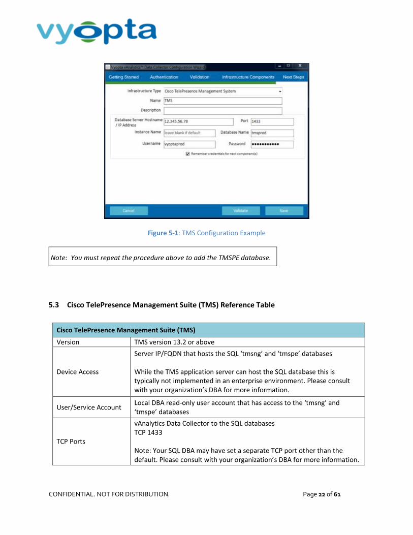
9. Make sure parameters are correctly enabled under Cisco Unified CM Administration for Active Publishers:
a. Navigate to Cisco Unified CM Administration -> System -> Service Parameters. b. Select Active Publishing Server(s). c. Select the Cisco Call Manager Service. d. Under System section set CDR Enabled Flag and CDR Log Calls with Zero Duration Flag to
True.
Note: The CDR Enabled Flag and CDR Log Calls with Zero Duration Flag must be set to True on every
Publisher and Subscriber – Subscribers do not inherit these values from Publishers, and these values are
not set by default. If not set correctly, CDRs will not be transmitted to vAnalytics and data loss is likely.
e. Under Cluster Wide parameters (Device - General) set Call Diagnostic Enabled to Enabled Regardless of CDR Enabled Flag and the two Show Line Group Member parameters to True.
Figure 6-4: Cisco Unified CM Administration Service Parameters
CONFIDENTIAL. NOT FOR DISTRIBUTION. Page 27 of 61
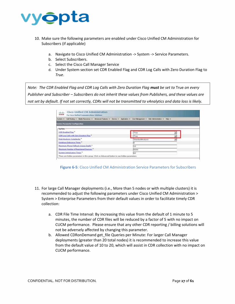
10. Make sure the following parameters are enabled under Cisco Unified CM Administration for Subscribers (if applicable)
a. Navigate to Cisco Unified CM Administration -> System -> Service Parameters. b. Select Subscribers. c. Select the Cisco Call Manager Service d. Under System section set CDR Enabled Flag and CDR Log Calls with Zero Duration Flag to
True.
Note: The CDR Enabled Flag and CDR Log Calls with Zero Duration Flag must be set to True on every
Publisher and Subscriber – Subscribers do not inherit these values from Publishers, and these values are
not set by default. If not set correctly, CDRs will not be transmitted to vAnalytics and data loss is likely.
Figure 6-5: Cisco Unified CM Administration Service Parameters for Subscribers
11. For large Call Manager deployments (i.e., More than 5 nodes or with multiple clusters) it is recommended to adjust the following parameters under Cisco Unified CM Administration > System > Enterprise Parameters from their default values in order to facilitate timely CDR collection:
a. CDR File Time Interval: By increasing this value from the default of 1 minute to 5 minutes, the number of CDR files will be reduced by a factor of 5 with no impact on CUCM performance. Please ensure that any other CDR reporting / billing solutions will not be adversely affected by changing this parameter.
b. Allowed CDRonDemand get_file Queries per Minute: For larger Call Manager deployments (greater than 20 total nodes) it is recommended to increase this value from the default value of 10 to 20, which will assist in CDR collection with no impact on CUCM performance.

CONFIDENTIAL. NOT FOR DISTRIBUTION. Page 28 of 61
6.3 Add CUCM Connectors for the Publisher
To add a CUCM Connector requires the following:
Access to the FQDN/ IP address of the video device from the vAnalytics Data Collector Previously created user service account credentials on each video device
Note: Only Publishers should be added. (No Subscribers should be added.) If Publisher services cannot
be enabled, please contact [email protected].
Please follow the instructions below to add each CUCM Publisher:
1. Select Cisco Unified Communications Manager (CUCM) from the Infrastructure Type menu. 2. Enter the infrastructure name. This will be the name displayed for the video device in the
Configuration Utility and within Vyopta’s Applications Management Portal.
Note: We recommend using hostname rather than IP as IP addresses are subject to change. It is also
helpful to name the infrastructure in a 'friendly' or easily understood way.
3. Enter the description of the video device. This can include the device type, location, and other unique identifiers.
4. Enter the infrastructure hostname or IP address. 5. Enter the username and password created on the video device. 6. Click Validate to ensure that the vAnalytics application can connect to the video device. 7. If the connection to the video component succeeded, click the Save button.
Figure 6-6: CUCM Configuration Example

CONFIDENTIAL. NOT FOR DISTRIBUTION. Page 29 of 61
6.4 Cisco Unified Communications Manager (CUCM) Reference Table
Cisco Unified Communications Manager (CUCM)
Version CUCM version 9.1 or above
Device Access Call Manager Publisher(s) IP/FQDN; Subscribers not required.
User/Service Account CUCM Application User with Standard CCM Read-only, AXL User Group, and Standard CTI Enabled, and Standard CTI Allow Control of Phones supporting Connected Xfer and conf
TCP Ports
vAnalytics Data Collector to CUCM TCP 443, 8443, 2748, 2749, 2789 CUCM to vAnalytics Data Collector Passive FTP (21) or SFTP* *FTP requires that passive FTP be open and allowed from CUCM to the Vyopta Data Collector. If SFTP is selected then only port 22 must be open. SFTP requires using a third party SFTP client on the Vyopta Data Collector.
Call Manager Service Requirements
Cisco Call Manager CISCO CTI Manager Cisco SOAP – CDRonDemand Service CISCO CAR Web Service Cisco AXL Web Service
Call Manager Service Parameters
‘CDR Enabled Flag’ and ‘CDR Log Calls with Zero duration’ to True ‘Call Diagnostic Enabled’ to Enabled Regardless and ‘Show Line Group Member’ parameters to true
CONFIDENTIAL. NOT FOR DISTRIBUTION. Page 30 of 61
7 Cisco Meeting Server (CMS; formerly Acano Server)
7.1 Set up a Service Account for Cisco Meeting Server (CMS)
To utilize CMS meeting and user reporting APIs, a service account with read-only administrator access
must be created:
1. SSH into the CMS box using any convenient command line utility. 2. Login with the Administrator account (e.g. [email protected]). 3. Enter the following command: user add vyopt a_svc api 4. Type in the vyopta_svc user account password.
Note: By default, CMS provisions new account passwords with a 180-day duration, meaning that you will
need to update the password on the service account twice yearly. If your corporate service account
policies permit, you may want to extend this default duration before adding the vyopta_svc account.
To change the default user account password duration, after logging into the CMS command line
interface with your administrator account, but before adding the vyopta_svc account, enter the
following command:
user rul e passwor d_age NNNN
where NNNN is the number of days before a password expires. So to set the default expiration to yearly, enter:
user rul e passwor d_age 365
If you have already added the Vyopta service account but want to extend its expiration duration, you still enter the
above command, followed by:
passwd vyopt a_svc
You'll then be prompted to confirm your administrator password to allow you to do this, then simply reenter the
existing password on the vyopta_svc account. It does not need to change to be refreshed -- and if you do change it,
you will need to update it on the vAnalytics apps management portal.

CONFIDENTIAL. NOT FOR DISTRIBUTION. Page 31 of 61
5. To verify that the API role is set (and the password expiration, if changed), enter the following command: user li st
6. Close the SSH session.
Figure 7-1: CMS User Account Information
7.2 Add a CMS Connector
To add a CMS Connector requires the following:
Access to your organization’s CMS Webpage from the vAnalytics Data Collector Credentials for the CMS read-only API service account established in the previous step (Section
7.1, Set up a Service Account for Cisco Meeting Server (CMS))
Please follow the instructions below to add the CMS instance:
1. Select either Cisco Meeting Server (CMS) or Acano Server, depending upon your version of the vAnalytics Data Collector, in the Infrastructure Type drop-down menu. (Only one of those two choices will be available.)
2. Enter the server name. 3. Enter the CMS URL into the Hostname.
Note: Please include any non-standard port number in the URL. For example:
10.200.30.24:445 (where 445 is the port number).
4. Enter an optional description of the video device in the Description field. 5. Enter the username and password of the service account established in the prior section. 6. Select Server Type (X2, X3 or VM). If VM, enter the number of ports for which your CMS is
licensed in the ‘Max concurrent 720p calls’ field.

CONFIDENTIAL. NOT FOR DISTRIBUTION. Page 32 of 61
Note: If you are on a fractionally licensed X2 / X3 then please add as a VM instead and specify your max
concurrent HD calls.
Figure 7-2: Adding CMS to vAnalytics
7. Click Validate to ensure that the vAnalytics can connect to your CMS. 8. If the connection to the video component succeeded, click the ‘Copy to Clipboard’ button in
order to capture the CDR URL which needs to be entered in CMS and then click the Save button. 9. Login to the CMS configuration portal using administrator credentials. 10. Navigate to Configuration > CDR Settings tab
a. If the Receiver URI 1 field is blank then paste the URL that you copied in step 8 into the ‘URI 1’ field. Otherwise paste the value into the ‘URI 2’ field.
b. Click Submit.
Figure 7-3: Adding CDR Receiver URL (CMS 1.8 and Higher)
11. For Acano versions prior to 1.8 or for deployments which require more than 2 CDR streams, please contact [email protected]

CONFIDENTIAL. NOT FOR DISTRIBUTION. Page 33 of 61
Note: Port 22280 is the default port over which the vAnalytics Data Collector will listen for inbound CMS
CDR data. If this port is not open in your network environment then please reach out to
[email protected] for further assistance.
7.3 Cisco Meeting Server (CMS) Reference Table
CMS
Version Acano 1.7 or above, CMS 2.0.0 or above
Device Access Server IP/FQDN of CMS device(s)
User/Service Account Local account with read-only API access enabled.
TCP Ports
vAnalytics Data Collector to CMS TCP 443* CMS CDR forward push to vAnalytics Data Collector TCP 22280 Note: the management port can be set to a separate port such as TCP so please confirm the correct port with your CMS administrator.

CONFIDENTIAL. NOT FOR DISTRIBUTION. Page 34 of 61
8 Cisco WebEx
8.1 Set up a Service Account for Cisco WebEx
To create a service account for Cisco WebEx, perform the following:
1. Log into the WebEx Web Portal using an existing site administrator account. 2. Select Site Administrator tab to open the Administration page. 3. Use the appropriate tab under Manage Users to create a new WebEx account:
a. Select the Site Admin – View only privilege. b. Enter Vyopt a for the First name. c. Enter Ser vi ce for the Last name. d. Enter vyopt asvc for the User name. e. Enter vyopt asvc @vyopt a. co m for the Email address. f. Set and confirm the password for the service account.
4. Select Update to save the service account information.
Figure 8-1: WebEx User Account Information

CONFIDENTIAL. NOT FOR DISTRIBUTION. Page 35 of 61
8.2 Add a WebEx Connector
To add a WebEx Connector requires the following:
Access to your organization’s WebEx Site URL from the vAnalytics Data Collector Credentials for the WebEx Site Admin - View only account
Please follow the instructions below to add your WebEx site:
1. Select Cisco WebEx in the Infrastructure Type drop-down menu. 2. Enter the WebEx site name. 3. Enter Web Ex into the Description field; you may also add the WebEx type, location, or other
unique identifiers. 4. Enter the WebEx Site URL in the Hostname field. 5. Enter the username and password of the Site Admin - View only account. 6. Click Validate to ensure that the vAnalytics application can connect. 7. If the connection succeeded, click the Save button.
Note: You must repeat the procedure above for each WebEx site.
Figure 8-2: Adding a WebEx Site

CONFIDENTIAL. NOT FOR DISTRIBUTION. Page 36 of 61
8.3 Cisco WebEx (Cloud only) Reference Table
Cisco WebEx (Cloud only)
Version Version T28 or above
Device Access FQDN of WebEx sites
User/Service Account Local Site Admin - View-only WebEx account
TCP Ports vAnalytics Data Collector to the WebEx Cloud TCP 443 (https)

CONFIDENTIAL. NOT FOR DISTRIBUTION. Page 37 of 61
9 Pexip Infinity
9.1 Validate the Service Account for Pexip Infinity
The account used by vAnalytics for connection to Pexip Infinity is the Pexip Management Node admin
account that is used to log into the Pexip Management Web Portal. To verify the credentials for the
Pexip Management Node, please follow these steps:
1. Open a web browser and navigate to the domain name or IP address of the Pexip Management Node.
2. Enter the admin username and password for the Pexip Management Node. 3. Ensure you can successfully log into the Pexip Management Node.
Figure 9-1: Pexip Management Node Login Page
Note: If the Pexip Management Node is LDAP-integrated, only a local admin account can be used for
the Vyopta vAnalytics Pexip Connector. If the User Authentication Source is set to LDAP database only,
the Pexip admin account must be used.
CONFIDENTIAL. NOT FOR DISTRIBUTION. Page 38 of 61
9.2 Add a Pexip Connector
To add a Pexip Connector requires the following:
Access through a web browser to the Pexip Node from the vAnalytics Data Collector
Credentials for the admin account on the Pexip Management Node from the previous section
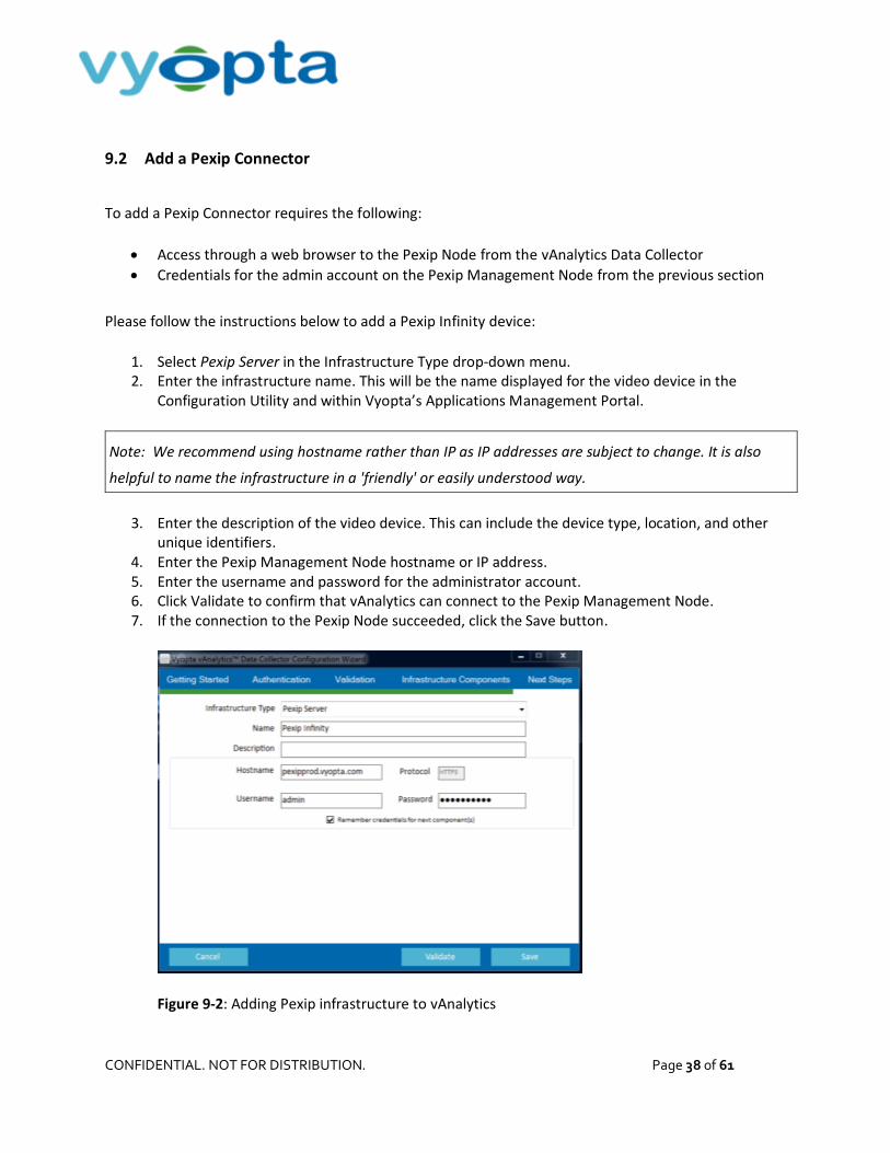
Please follow the instructions below to add a Pexip Infinity device:
1. Select Pexip Server in the Infrastructure Type drop-down menu. 2. Enter the infrastructure name. This will be the name displayed for the video device in the
Configuration Utility and within Vyopta’s Applications Management Portal.
Note: We recommend using hostname rather than IP as IP addresses are subject to change. It is also
helpful to name the infrastructure in a 'friendly' or easily understood way.
3. Enter the description of the video device. This can include the device type, location, and other unique identifiers.
4. Enter the Pexip Management Node hostname or IP address. 5. Enter the username and password for the administrator account. 6. Click Validate to confirm that vAnalytics can connect to the Pexip Management Node. 7. If the connection to the Pexip Node succeeded, click the Save button.
Figure 9-2: Adding Pexip infrastructure to vAnalytics

CONFIDENTIAL. NOT FOR DISTRIBUTION. Page 39 of 61
9.3 Pexip Infinity Reference Table
Pexip Infinity
Version Pexip Infinity 10 or above
Device Access Server IP/FQDN of Pexip Management Node(s)
User/Service Account Local account with full Administrator access
TCP Ports vAnalytics Data Collector to Pexip Management Node(s) TCP 443*

CONFIDENTIAL. NOT FOR DISTRIBUTION. Page 40 of 61
10 Microsoft Lync Server
10.1 Set up a Service Account for Microsoft Lync Server
The service account for this device will be added to the appliance’s SQL Database, with read-only
privileges. You must determine where the appliance’s SQL Server Database is located in your
environment; whether it is on the appliance or located on a different server.
Once you have identified where the SQL Server is located, you will have to verify that the server has
Microsoft SQL Server Management Studio or download the software application on your local computer.
To create a service account on the Lync SQL Server, perform the following:
1. Log into the Microsoft Lync’s Server via a remote desktop connection. 2. Navigate through the start menu to Microsoft SQL Server Management Studio. 3. Log in with a SQL Server Administrator account or Local Administrator account.
4. Navigate the folder structure to find the Security > Logins folder. 5. Right click on the Logins folder and choose New Login, which should display the following:
Figure 10-1: SQL User Creation Screen
Note: The administrator account must have write privileges to create a service account.

CONFIDENTIAL. NOT FOR DISTRIBUTION. Page 41 of 61
6. Create a local database user account with the following information: 7. Fill in the Login Name. 8. Select the SQL Server Authentication. 9. Assign a Password and confirm the password. 10. Uncheck Enforce Password Policy. 11. Select User Mapping in the left hand column. 12. Select the LcsCDR database to provide the account access to the database. 13. Once the database has been selected, you must identify the role membership. Ensure that the
db_datareader and public roles are selected. 14. Repeat steps 8 and 9 for the QoEMetrics database in the database List. 15. Click OK to create the user.
Figure 10-2: SQL User Mapping Screen

CONFIDENTIAL. NOT FOR DISTRIBUTION. Page 42 of 61
16. You will need to identify the Instance Name of the SQL Server hosting the Lync database that will be the target of the vAnalytics Data Collector. Your database administrator may be able to provide this information directly, or you can perform the following:
a. Open the Microsoft SQL Server Configuration Manager application and select the SQL Server Services tab as displayed below:
Figure 10-3: SQL Server Configuration Manager
b. Identify the Instance Name of the SQL Server hosting the Lync Database. In the example above the SQL Server Instance Name is RTC.
c. Document this information to use in adding the vAnalytics Lync Connector.
You have now created a new database read-only user account on the Lync database. This account is
configured to be a service account for use in the vAnalytics System Configuration Utility to set up the
connection to the appropriate service.
10.2 Add a Microsoft Lync Server Connector
To add a Microsoft Lync Server Connector requires the following:
Access to the FQDN/IP address of the Server hosting the Lync SQL Databases from the vAnalytics Data Collector
Credentials for the Microsoft SQL Server Account
Knowledge of the SQL port type (static or dynamic) and if dynamic, the port value defined within Microsoft SQL Configuration Manager
TCP/IP Connectivity enabled for the SQL Server within SQL Configuration Manager

CONFIDENTIAL. NOT FOR DISTRIBUTION. Page 43 of 61
Please follow the instructions below to add Microsoft Lync:
1. Select Microsoft Lync in the Infrastructure Type drop-down menu. 2. Enter the infrastructure name. This will be the name displayed for the video device in vAnalytics.
Note: We recommend using hostname rather than IP as IP addresses are subject to change. It is also
helpful to name the infrastructure in a 'friendly' or easily understood way.
3. Enter the description of the video device. This can include the device type, location, and other unique identifiers.
4. Enter the SQL Server hostname or IP address. 5. Add the SQL Server Instance Name as a suffix to the Hostname or IP address:
e.g., <Device Hostname>\<SQL Server Instance Name>
6. Enter the username and password of the SQL Server account created in the previous section. 7. Leave the Port Number and Database Name of the SQL Server blank. 8. Click Validate to ensure that the vAnalytics application can connect to the video device. 9. If the connection to the video component succeeded, click the Save button.
10.3 Microsoft Skype for Business/Lync Reference Table
Skype for Business/Lync
Version Version 2010 or above
Device Access Server IP/FQDN of S4B/Lync database server/cluster responsible for reporting
User/Service Account Local read-only database account that has access to the ‘LcsCDR’ and ‘QoEMetrics’ databases.
TCP Ports
* vAnalytics Data Collector to SQL database server/cluster TCP 1433* * Port can vary depending on customer environment; Exact port to be provided by Customer Lync DBA team

CONFIDENTIAL. NOT FOR DISTRIBUTION. Page 44 of 61
11 Polycom RealPresence Distributed Media Application (DMA)
11.1 Verify API Licensing and Set up Service Account for Polycom RealPresence Distributed
Media Application (DMA)
Note: The Polycom DMA must have the appropriate API License in order to activate the API for use with
external applications. Confirm that the RealPresence Platform API is licensed through the DMA
management interface as shown below:
Figure 11-1: Polycom API Licensing
To confirm that the RealPresence Platform API is licensed, please complete the following:
1. Log into the DMA Management Interface. 2. Navigate to the Dashboard. 3. Add the License Status Panel (not added by default). 4. Ensure that the RealPresence Platform API displays Licensed.
Once the API has been verified or activated, a service account, which must be a local account with
administrator credentials, is required. To add and verify the credentials for Polycom DMA, complete the
following:
CONFIDENTIAL. NOT FOR DISTRIBUTION. Page 45 of 61
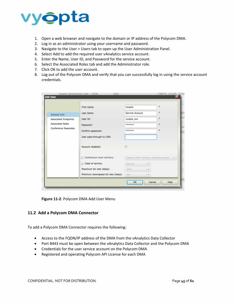
1. Open a web browser and navigate to the domain or IP address of the Polycom DMA. 2. Log in as an administrator using your username and password. 3. Navigate to the User > Users tab to open up the User Administration Panel. 4. Select Add to add the required user vAnalytics service account. 5. Enter the Name, User ID, and Password for the service account. 6. Select the Associated Roles tab and add the Administrator role. 7. Click OK to add the user account. 8. Log out of the Polycom DMA and verify that you can successfully log in using the service account
credentials.
Figure 11-2: Polycom DMA Add User Menu
11.2 Add a Polycom DMA Connector
To add a Polycom DMA Connector requires the following:
Access to the FQDN/IP address of the DMA from the vAnalytics Data Collector
Port 8443 must be open between the vAnalytics Data Collector and the Polycom DMA
Credentials for the user service account on the Polycom DMA
Registered and operating Polycom API License for each DMA

CONFIDENTIAL. NOT FOR DISTRIBUTION. Page 46 of 61
Please follow the instructions below to add each DMA instance:
1. Select Polycom DMA from the Infrastructure Type drop-down menu. 2. Enter the infrastructure name. This will be the name displayed for the video device in the
Configuration Utility and within Vyopta’s Applications Management Portal.
Note: We recommend using hostname rather than IP as IP addresses are subject to change. It is also
helpful to name the infrastructure in a 'friendly' or easily understood way.
3. Enter the description of the device. This can include the device type, location, and other unique identifiers.
4. Enter the hostname or IP address followed by : 8443 5. Enter the username and password for the user service account. 6. Click Validate to ensure that the vAnalytics application can connect. 7. If the connection to the Polycom device succeeds, click the Save button.
Figure 11-3: Polycom DMA Configuration Example

CONFIDENTIAL. NOT FOR DISTRIBUTION. Page 47 of 61
11.3 Polycom RealPresence Distributed Media Application (DMA) Reference Table
Polycom RealPresence Distributed Media Application (DMA)
Version DMA version 6.2 or above
Device Access Server IP/FQDN
User/Service Account Local account with full Administrator read/write or Provisioner privileges.
TCP Ports vAnalytics Data Collector to the DMA device(s) TCP 8443
API License Note: Requires the RealPresence Platform API license per DMA device

CONFIDENTIAL. NOT FOR DISTRIBUTION. Page 48 of 61
12 Polycom RealPresence Collaboration server (RMX)
12.1 Set up a Service Account for Polycom RealPresence Collaboration server (RMX)
The required service account must be an account with full read/write administrator credentials. The
Polycom API will not allow an administrator account with read-only privileges to retrieve CDR data. To
add and verify the credentials for the Polycom RMX, complete the following:
1. In the Polycom RMX Manager application click Users. 2. Click New User to open the User Properties dialog box. 3. Enter the username vyopt a_svc in the User Name field for the vAnalytics user service account. 4. Enter the password in the Password field. 5. Select Administrator in the Authorization Level drop-down field. 6. Click OK to add the user account. 7. Log out of the Polycom RMX Manager application and verify that you can successfully log in
using the service account credentials.
Figure 12-1: Polycom RMX Add User Menu
CONFIDENTIAL. NOT FOR DISTRIBUTION. Page 49 of 61
12.2 Add a Polycom RMX Connector
To add a Polycom RMX Connector requires the following:
Access to the FQDN/IP address of the RMX from the vAnalytics Data Collector
Port 80/443 must be open between the vAnalytics Data Collector and the Polycom RMX
Credentials for the user service account on the Polycom RMX
Please follow the instructions below to add each RMX instance:
1. Select Polycom RMX from the Infrastructure Type drop-down menu. 2. Enter the infrastructure name. This will be the name displayed for the video device in the
Configuration Utility and within Vyopta’s Applications Management Portal.
Note: We recommend using hostname rather than IP as IP addresses are subject to change. It is also
helpful to name the infrastructure in a 'friendly' or easily understood way.
3. Enter the description of the device. This can include the device type, location, and other unique identifiers.
4. Enter the hostname or IP address. 5. Enter the username and password for the user service account. 6. Click Validate to ensure that the vAnalytics application can connect. 7. If the connection to the Polycom RMX device succeeds, click the Save button.

CONFIDENTIAL. NOT FOR DISTRIBUTION. Page 50 of 61
Figure 12-2: Polycom RMX Configuration Example
12.3 Polycom RealPresence Collaboration server (RMX) Reference Table
Polycom RealPresence Collaboration server (RMX)
Version RMX 8.5 or above
Device Access Server IP/FQDN
User/Service Account Local account with full Administrator read/write or privileges. Note: unable to use RMX read-only administrator due to limitation with API for CDR access.
TCP Ports vAnalytics Data Collector to the RMX device(s) TCP 80/443

CONFIDENTIAL. NOT FOR DISTRIBUTION. Page 51 of 61
13 Polycom RealPresence Resource Manager (RPRM)
13.1 Verify API Licensing and Set up a Service Account for Polycom RealPresence Resource
Manager (RPRM)
Similar to Polycom DMA (see Section 11.1 - Verify API Licensing and Set up a Service Account for Polycom
RealPresence Distributed Media Application (DMA)), the Polycom RPRM must have the appropriate API
license in order to activate the API for use with external applications. Once the API has been verified or
activated, a service account, which must be a local account with administrator credentials, is required.
To add and verify the credentials for Polycom RPRM complete the following:
1. Open a web browser and navigate to the domain or IP address of the Polycom RPRM. 2. Log in as an administrator using your username and password. 3. Navigate to the User > Users tab to open up the User Administration Panel. 4. Select Add to add the required vAnalytics user service account. 5. Enter the Name, User ID, and Password for the service account. 6. Select the Associated Roles tab and add the Administrator role. 7. Click OK to add the user account. 8. Log out of the Polycom RPRM and verify that you can successfully log in using the service
account credentials.
Figure 13-1: Polycom RPRM Add User Associated Roles Menu

CONFIDENTIAL. NOT FOR DISTRIBUTION. Page 52 of 61
13.2 Add a Polycom RPRM Connector
To add a Polycom RPRM Connector requires the following:
Access to the FQDN/IP address of the RPRM from the vAnalytics Data Collector Port 8443 must be open between the vAnalytics Data Collector and the Polycom RPRM Credentials for the user service account on the Polycom RPRM Registered and operating Polycom API License for each RPRM
Please follow the instructions below to add each RPRM instance:
1. Select Polycom RealPresence Resource Manager from the Infrastructure Type drop-down menu. 2. Enter the infrastructure name. This will be the name displayed for the video device in the
Configuration Utility and within Vyopta’s Applications Management Portal.
Note: We recommend using hostname rather than IP as IP addresses are subject to change. It is also
helpful to name the infrastructure in a 'friendly' or easily understood way.
3. Enter the description of the device. This can include the device type, location, and other unique identifiers.
4. Enter the hostname or IP address followed by : 8443 5. Enter the username and password for the user service account. 6. Click Validate to ensure that the vAnalytics application can connect. 7. If the connection to the Polycom device succeeds, click the Save button.
Figure 13-2: Polycom RPRM Configuration Example

CONFIDENTIAL. NOT FOR DISTRIBUTION. Page 53 of 61
13.3 Polycom RealPresence Resource Manager (RPRM) Reference Table
Polycom RealPresence Resource Manager (RPRM)
Version RPRM version 8.2 or above
Device Access Server IP/FQDN
User/Service Account Local account with full Administrator read/write, device administrator or Operator privileges
TCP Ports vAnalytics Data Collector to RPRM TCP 8443
API License Note: Requires the RealPresence Platform API license
CONFIDENTIAL. NOT FOR DISTRIBUTION. Page 54 of 61
14 Vidyo Management Portal
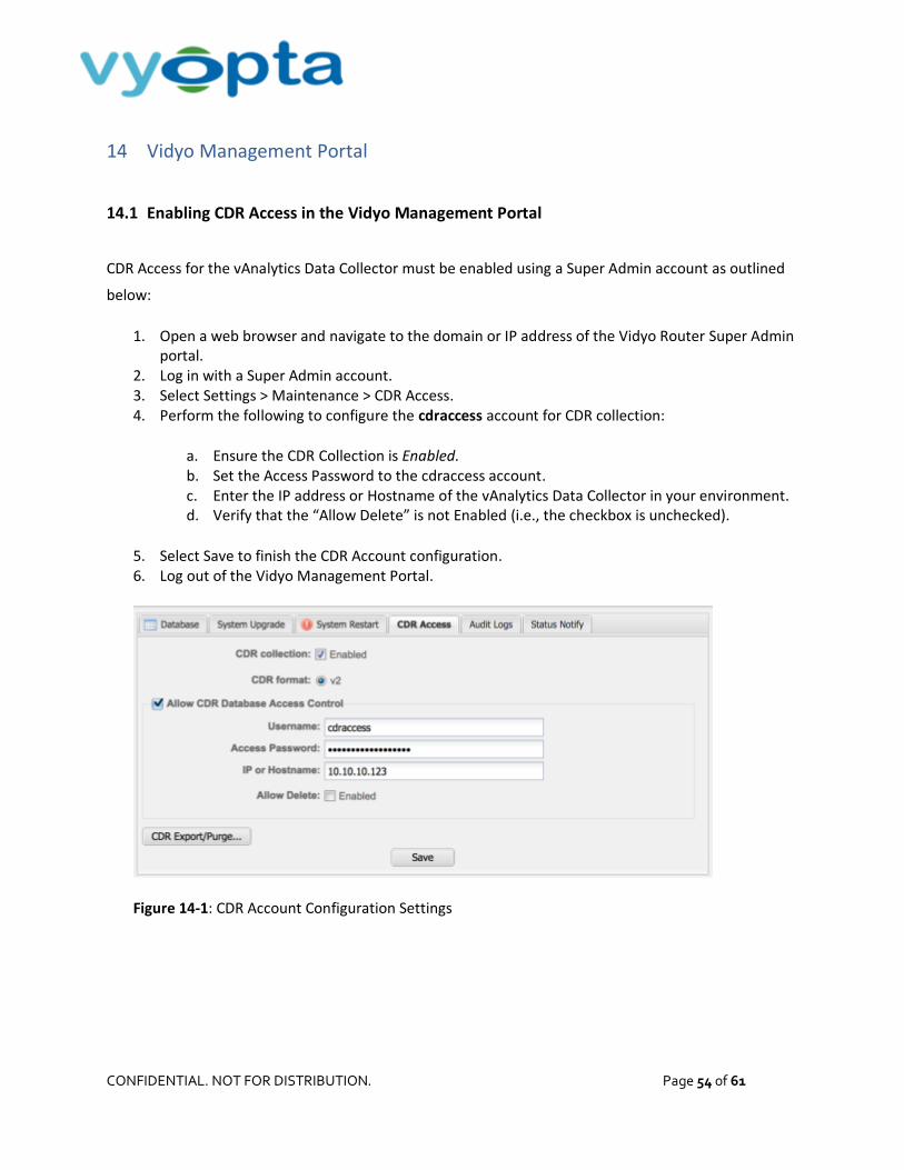
14.1 Enabling CDR Access in the Vidyo Management Portal
CDR Access for the vAnalytics Data Collector must be enabled using a Super Admin account as outlined
below:
1. Open a web browser and navigate to the domain or IP address of the Vidyo Router Super Admin portal.
2. Log in with a Super Admin account. 3. Select Settings > Maintenance > CDR Access. 4. Perform the following to configure the cdraccess account for CDR collection:
a. Ensure the CDR Collection is Enabled. b. Set the Access Password to the cdraccess account. c. Enter the IP address or Hostname of the vAnalytics Data Collector in your environment. d. Verify that the “Allow Delete” is not Enabled (i.e., the checkbox is unchecked).
5. Select Save to finish the CDR Account configuration. 6. Log out of the Vidyo Management Portal.
Figure 14-1: CDR Account Configuration Settings

CONFIDENTIAL. NOT FOR DISTRIBUTION. Page 55 of 61
14.2 Add a Vidyo Management Portal Connector
To add a Vidyo Management Portal Connector requires the following:
Access to the Vidyo Management Portal and database from the vAnalytics Data Collector
Credentials for the cdraccess account on the Vidyo Management Portal
Please follow the instructions below to add the video appliance:
1. Select Vidyo Router in the Infrastructure Type drop-down menu. 2. Enter a suitable name and description into the appropriate fields.
Note: We recommend using hostname rather than IP as IP addresses are subject to change. It is also
helpful to name the infrastructure in a 'friendly' or easily understood way.
3. Enter the Vidyo Management Portal IP address or Hostname. 4. Enter cdr access for the Username and the appropriate Password for the Account. 5. Click Validate to ensure that the vAnalytics application can connect. 6. If the connection to the video component succeeded, click the Save button.
Figure 14-2: Vidyo Infrastructure Information Example

CONFIDENTIAL. NOT FOR DISTRIBUTION. Page 56 of 61
14.3 Vidyo Management Portal Reference Table
VIDYO Management Portal
Version Vidyo version 3.1 or above
Device Access Server IP/FQDN of Vidyo Management Portal
User/Service Account Local read-only account named ‘cdraccess’
TCP Ports vAnalytics Data Collector to Vidyo Management Portal TCP 443 & 3306

CONFIDENTIAL. NOT FOR DISTRIBUTION. Page 57 of 61
15 Saving the vAnalytics™ Configuration and Starting the vAnalytics™ Service
15.1 Saving the vAnalytics™ Configuration and Starting the vAnalytics™ Service
After you have successfully added all of your video devices into the vAnalytics Configuration Utility, click
the Next button and you will see the wizard starting the vAnalytics Service.
Figure 15-1: Vyopta vAnalytics Configuration Wizard
Congratulations! You have now installed and configured Vyopta’s vAnalytics Data Collector within your
video collaboration environment. It will take approximately 2 days to populate historical data in
vAnalytics™, but you should be able to start seeing real-time data immediately, so go ahead and log in
at http://vanalytics.vyopta.com now! If you have any questions or require assistance, please contact

CONFIDENTIAL. NOT FOR DISTRIBUTION. Page 58 of 61
15.2 Troubleshooting a Failed Connection
If you receive an error while adding a video infrastructure device, there are a number of components
that could be the result of the issue. Depending on your IT Organization, this typically requires
involvement from your Network Administrator. There are, however, steps that you can use to
troubleshoot your network connection.
Attempting to connect to the video device from a web browser will determine if the issue is with the
connection to the infrastructure, a problem with the account on the video device, or information
entered while adding the video device to the vAnalytics Configuration Utility. Please try the following
steps to resolve these issues:
1. Open a web browser such as Chrome, Firefox, or Internet Explorer. 2. In your browser, type in the host name or IP address of the video device, then press enter. Wait
for the webpage to load. 3. If you are unable to connect to the video device through a web browser, please verify that you
are using the proper protocol (HTTP or HTTPS). 4. If you are able to connect to the video device through a web browser, verify that the web
protocol matches the protocol used while adding the infrastructure. 5. Log into the video device using the configured username and password on the video device that
was set up as part of the configuration process. 6. If you are unable to log in, ensure that you have the proper credentials for the account on the
video device. 7. If you are able to log into the video device with the account credentials, ensure that the account
is properly configured on the device.
If you continue to have issues connecting to the video device, you may have a network configuration
issue or network proxy in place that needs to be addressed in the vAnalytics configuration. Please reach
out to your network administrator to troubleshoot the network connection or contact
[email protected] for further assistance.

CONFIDENTIAL. NOT FOR DISTRIBUTION. Page 59 of 61
16 SolarWinds Integration
The Vyopta SolarWinds Integration allows you to monitor video conferences in coordination with your
SolarWinds environment by enabling single click access to the network interface from video endpoints in
Vyopta vAnalytics. This in turn enables faster resolutions to video issues by equipping UC managers and
video team engineers with the ability to jump directly from real-time video issues to underlying network
data. Please note that there must be at least one Cisco switch in your environment to proceed.
16.1 Requirements
To begin setup for the SolarWinds integration, please have:
1. Credentials for a local SolarWinds account with Read Only Access (without account restrictions). 2. The IP of the SolarWinds server:8787
Please also note the following prerequisites:
1. Interfaces on Cisco switches must be enabled. 2. CDP must be enabled on switches and endpoints. 3. Endpoint Monitor Software version must be version 3.1.3.15 or higher.
Figure 16-1: The Endpoint Monitor Version as seen in Status tab
Note: To verify Endpoint Monitor version, log into apps.vyopta.com and check Admin Status. If you
need to upgrade Endpoint Monitor, or do not have Endpoint Monitor, please contact
[email protected] for assistance.

CONFIDENTIAL. NOT FOR DISTRIBUTION. Page 60 of 61
4. Endpoint Monitor service should have the vControl Config left blank
Figure 16-2: The Endpoint Monitor Version as seen in Status tab
16.2 Configuration
Configuring and enabling the SolarWinds integration can be accomplished by doing the following:
1. Log into apps.vyopta.com with an account provisioned for Administrator access 2. Navigate to vControl vControl Configs Default Config Config Item 3. Enter the SolarWinds Server URL/IP:8787, Username, and Password as indicated below
Figure 16-3: View of vControl configuration
Note: For the SolarWinds URL, it should have the default SolarWinds Information Service port in the
url(SWIS): 8787

CONFIDENTIAL. NOT FOR DISTRIBUTION. Page 61 of 61
16.3 Verification
The integration should now be configured and should sync within a few hours. Once it has, it can be
verified by logging into vAnalytics Realtime and navigating to the Endpoints tab. From there, you should
be able to verify that the SolarWinds icon is shown.
Figure 16-4: SolarWinds icons in vAnalytics Realtime-> Endpoints tab
If the SolarWinds icon does not appear by the following day, reach out to [email protected] for further assistance. If you can see the SolarWinds logo, the integration is now ready to go!