vanguard applications ware tcp-to-bsc conversion … · configuring tcp to bsc tables ... bsc3270...
TRANSCRIPT

Vanguard Applications WareTCP-to-BSC Conversion (VBIP)

Notice
©2008 Vanguard Networks 25 Forbes Boulevard Foxboro, Massachusetts 02035 (508) 964-6200 All rights reserved Printed in U.S.A..
Restricted Rights Notification for U.S. Government Users
The software (including firmware) addressed in this manual is provided to the U.S. Government under agreement which grants the government the minimum “restricted rights” in the software, as defined in the Federal Acquisition Regulation (FAR) or the Defense Federal Acquisition Regulation Supplement (DFARS), whichever is applicable.
If the software is procured for use by the Department of Defense, the following legend applies:
Restricted Rights LegendUse, duplication, or disclosure by the Government
is subject to restrictions as set forth in subparagraph (c)(1)(ii) of the
Rights in Technical Data and Computer Software clause at DFARS 252.227-7013.
If the software is procured for use by any U.S. Government entity other than the Department of Defense, the following notice applies:
NoticeNotwithstanding any other lease or license agreement that may pertain to, or accompany the delivery of, this computer software, the rights of the Government regarding its use, reproduction, and disclosure are as set forth in FAR 52.227-19(C).
Unpublished - rights reserved under the copyright laws of the United States.
Notice (continued)
Proprietary Material
Information and software in this document are proprietary to Vanguard Networks. (or its Suppliers) and without the express prior permission of an officer of Vanguard Networks, may not be copied, reproduced, disclosed to others, published, or used, in whole or in part, for any purpose other than that for which it is being made available. Use of software described in this document is subject to the terms and conditions of the Vanguard Networks Software License Agreement.
This document is for information purposes only and is subject to change without notice.
To comment on this manual, please send e-mail to [email protected]
Part No. T0290, Rev A Publication Code: TKFirst Printing: October 2008Manual is current for Release 7.1 of Vanguard Applications Ware.

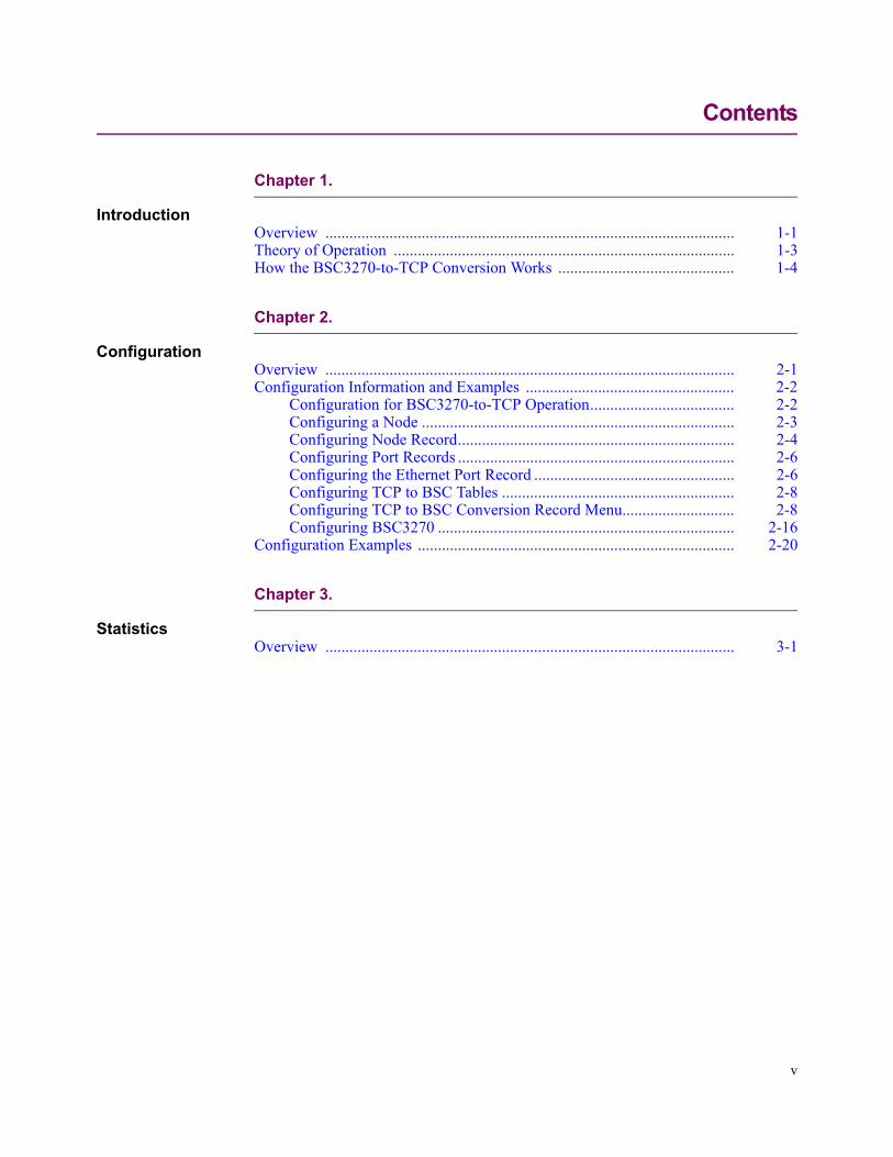
Contents
v
Chapter 1.
IntroductionOverview ...................................................................................................... 1-1Theory of Operation ..................................................................................... 1-3How the BSC3270-to-TCP Conversion Works ............................................ 1-4
Chapter 2.
ConfigurationOverview ...................................................................................................... 2-1Configuration Information and Examples .................................................... 2-2
Configuration for BSC3270-to-TCP Operation.................................... 2-2Configuring a Node .............................................................................. 2-3Configuring Node Record..................................................................... 2-4Configuring Port Records ..................................................................... 2-6Configuring the Ethernet Port Record .................................................. 2-6Configuring TCP to BSC Tables .......................................................... 2-8Configuring TCP to BSC Conversion Record Menu............................ 2-8Configuring BSC3270 .......................................................................... 2-16
Configuration Examples ............................................................................... 2-20
Chapter 3.
StatisticsOverview ...................................................................................................... 3-1


Introduction 1-1
T0290, Revision A Release 7.1
Chapter 1Introduction
Overview
Introduction The purpose of this document is to describe the BSC3270 to TCP/IP conversion feature targeted for a remote 3400 model Vanguard router.
TCP to BSC Conversion
The BSC3270 to TCP/IP conversion feature provides an alternative means of termination into the (HP (Tandem) or IBM (mainframe) host using TCP/IP communications subsystem specifically for Automated Teller Machine (ATM) service providers and bank networks. This feature allows banks and ATM network providers to retain BSC3270 attached ATMs while providing LAN/WAN connection with the host. Figure 1-1 illustrates BSC3270 to TCP/IP conversion components within the Vanguard router.
Figure 1-1. BSC3270 to TCP/IP Conversion
Automated Teller Machine (ATM)
The acronym (ATM) in this manual refers to Automatic Teller Machine.
NoteDo not confuse Automated Teller Machine with Asynchronous Transfer Mode, a cell-switching and multiplexing protocol.
Before Using This Manual
Before using this manual you should have experience using IBM or IBM-compatible equipment. You should be familiar with the IBM Binary Synchronous Communications (BSC) protocol and IP routing.
Trademarks The following are trademarks or registered trademarks of their respective companiesor organizations:
• Vanguard and Vanguide are trademarks or registered trademarks of Vanguard Networks, LLC
HostATM
IP TCP TCP/IPCONVERSION DSP BSC
3270
Vanguard 3400
1-2 Introduction
• IBM is the registered trademark of International Business Machines Corpora-tion
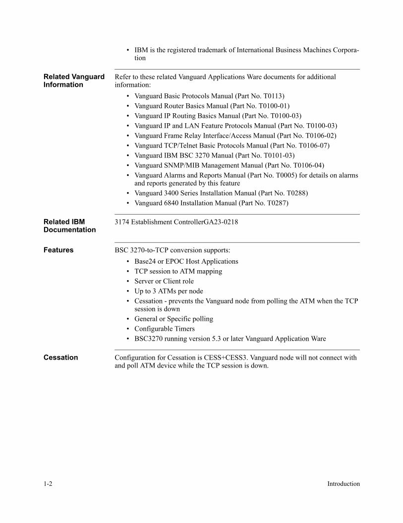
Related Vanguard Information
Refer to these related Vanguard Applications Ware documents for additional information:
• Vanguard Basic Protocols Manual (Part No. T0113)• Vanguard Router Basics Manual (Part No. T0100-01)• Vanguard IP Routing Basics Manual (Part No. T0100-03)• Vanguard IP and LAN Feature Protocols Manual (Part No. T0100-03)• Vanguard Frame Relay Interface/Access Manual (Part No. T0106-02)• Vanguard TCP/Telnet Basic Protocols Manual (Part No. T0106-07)• Vanguard IBM BSC 3270 Manual (Part No. T0101-03)• Vanguard SNMP/MIB Management Manual (Part No. T0106-04)• Vanguard Alarms and Reports Manual (Part No. T0005) for details on alarms
and reports generated by this feature• Vanguard 3400 Series Installation Manual (Part No. T0288)• Vanguard 6840 Installation Manual (Part No. T0287)
Related IBM Documentation
3174 Establishment ControllerGA23-0218
Features BSC 3270-to-TCP conversion supports:• Base24 or EPOC Host Applications• TCP session to ATM mapping• Server or Client role• Up to 3 ATMs per node• Cessation - prevents the Vanguard node from polling the ATM when the TCP
session is down• General or Specific polling• Configurable Timers• BSC3270 running version 5.3 or later Vanguard Application Ware
Cessation Configuration for Cessation is CESS+CESS3. Vanguard node will not connect with and poll ATM device while the TCP session is down.
Introduction 1-3
T0290, Revision A Release 7.1
Theory of Operation
Theory of Operation
Introduction The BSC3270 to TCP/IP conversion feature is designed to function in a remote Vanguard 3400 series router with sufficient memory and flash resources to support IP routing features, including BGP-4, QOS, Firewall, VPN, SSH Server, RADIUS Client, and SNMP for specific traps required for host status notification. The theory of operation presented in the following subsection provides a basic description of how the BSC3270-to-TCP conversion feature is implemented in Vanguard products.Among the financial industries host application programs supported are Base24 and EPOC, both of which run on an IBM or HP (Tandem) host platforms. The host application controls the ATM and all of its functions from displaying data, printing, and currency distribution. Currently there is a significant number of ATM machines installed that use BSC3270 which requires a serial connection in the data center typically using an IBM-like Communications Controller or HP (Tandem) SWAN controller. Depending on the number of remote ATM machines this can result in hundreds of serial (leased) lines in the data center which for cost and maintenance reasons could be undesirable. The BSC3270 to TCP/IP conversion feature in the Vanguard router allows users to retain the remote BSC3270 ATM machines and connect them at the host using TCP/IP over a LAN interface, eliminating the need for serial line connections at the host.Vanguard Networks was the first company to develop BSC3270 to SNA conversion allowing LAN connections at the host using IBM’s SNA architecture. The new BSC3270 to TCP/IP feature ‘VBIP’ now adds host connectivity to include TCP/IP over a LAN/WAN connection.

1-4 Introduction
How the BSC3270-to-TCP Conversion Works
How the BSC3270-to-TCP Conversion Works
Introduction BSC3270-to-TCP conversion is used in the financial, banking and network provider-environments where ATM’s are networked into:
• Tandem K Series host computers• Tandem S Series host computers• Central-site IBM 3745 communications controllers• Stratus Hosts• IBM S/390 Servers
Purpose The BSC3270-to-TCP conversion allows banks and ATM network providers to retain BSC3270 attached ATMs while providing a LAN/WAN connection with the host.This feature will allow the attached BSC3270 ATM machine to appear as a TCP/IP device, complete with its unique IP device address and TCP port address, mutually exclusive to the inherent IP router capability, running in the same physical node.
Typical Application Application #1 shown in Figure 1-2 below shows a typical application of BSC3270-to-TCP conversion. The network consists of these elements:
• Tandem Host• Frame Relay WAN• Vanguard 3410• ATMs
Figure 1-2. Typical BSC3270-to-TCP Application
MPLSNetwork
Vanguard 3400Application 1
Application 2Vanguard 3410
BSC3270
BSC3270
Ethernet
ATM
ATM
Data Center
HP (Tandem) ServerHost Base 24 Application
TCP/IP access pointdirectly into the Base24protocol stack bypassingthe need for ACI/ICE

Introduction 1-5
T0290, Revision A Release 7.1
How the BSC3270-to-TCP Conversion Works
Data Conversion Figure 1-3 below shows the changes in the data formats as the packets pass through the network. Conversion is done in the Vanguard 3410.
Figure 1-3. Data Conversion Diagram
Application Header Device Status
In the example shown Figure 1-4 in the frame contains source and destination MAC, IP and TCP port addresses.The IP packet begins with inclusion of the VBIP header which in this case contains an "ATM Active' '00 80' status byte indicator. When status is sent to the host the Length field is '00' without any packet or application data. The Base24 application when configured to support VBIP requires at a minimum 'ATM Active' and 'ATM Inactive' status. In cases this may the only status required by Base24.
Figure 1-4. Application Header Status Diagram
ATM Active: Sent when the BSC3270 TPAD sends a specific poll to the ATM and received a valid (EOT) response. ATM Active status is also used as a ‘wake up’ to the Base24 application indicating the downstream ATM machine is ready for activation or download.
Tandem Host
Ethernet TCPHeader
IPHeader
ApplHeader Data
Vanguard 3410
TCP to BSC
ATM
Bisync TCP/IP
BSCHeader
BSCData
Source IP Dest. IPIP Header: 45 00 00 37 00 04 00 00 FF 06 ED D9 AA 87 3C 70 AA 87 3C 64
S Port D Port
TCP Header: 07 AB 71 4B A6 3D 44 A1 6A 05 FE 0E 50 18 27 F4 EA 12 00 00
Length Status
*APPL Header: 00 00 00 80
0 0 0 0 0 0 0 0 1 0 0 0 0 0 0 0
Packet Data: 00
Source IP Dest. IPSource IP Dest. IPIP Header: 45 00 00 37 00 04 00 00 FF 06 ED D9 AA 87 3C 70 AA 87 3C 64
S Port D Port
TCP Header: 07 AB 71 4B A6 3D 44 A1 6A 05 FE 0E 50 18 27 F4 EA 12 00 00
S Port D Port
TCP Header: 07 AB 71 4B A6 3D 44 A1 6A 05 FE 0E 50 18 27 F4 EA 12 00 00
Length Status
*APPL Header: 00 00 00 80
0 0 0 0 0 0 0 0 1 0 0 0 0 0 0 0
Packet Data: 00
1-6 Introduction
How the BSC3270-to-TCP Conversion Works
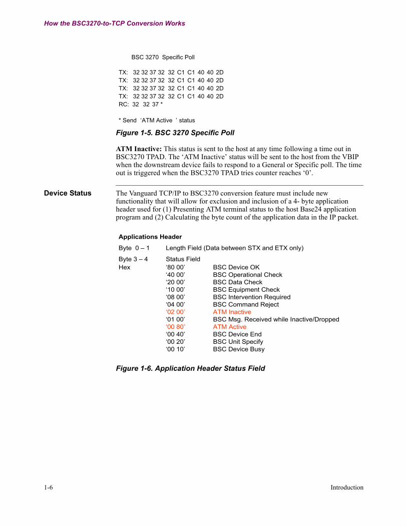
Figure 1-5. BSC 3270 Specific Poll
ATM Inactive: This status is sent to the host at any time following a time out in BSC3270 TPAD. The ‘ATM Inactive’ status will be sent to the host from the VBIP when the downstream device fails to respond to a General or Specific poll. The time out is triggered when the BSC3270 TPAD tries counter reaches ‘0’.
Device Status The Vanguard TCP/IP to BSC3270 conversion feature must include new functionality that will allow for exclusion and inclusion of a 4- byte application header used for (1) Presenting ATM terminal status to the host Base24 application program and (2) Calculating the byte count of the application data in the IP packet.
Figure 1-6. Application Header Status Field
BSC 3270 Specific Poll
TX: 32 32 37 32 32 C1 C1 40 40 2DTX: 32 32 37 32 32 C1 C1 40 40 2DTX: 32 32 37 32 32 C1 C1 40 40 2DTX: 32 32 37 32 32 C1 C1 40 40 2DRC: 32 32 37 *
* Send ‘ATM Active ’ status
Applications Header
Byte 0 – 1 Length Field (Data between STX and ETX only)
Byte 3 – 4 Status FieldHex ‘80 00’ BSC Device OK
‘40 00’ BSC Operational Check‘20 00’ BSC Data Check‘10 00’ BSC Equipment Check‘08 00’ BSC Intervention Required‘04 00’ BSC Command Reject‘02 00’ ATM Inactive‘01 00’ BSC Msg. Received while Inactive/Dropped‘00 80’ ATM Active‘00 40’ BSC Device End‘00 20’ BSC Unit Specify‘00 10’ BSC Device Busy

Introduction 1-7
T0290, Revision A Release 7.1
How the BSC3270-to-TCP Conversion Works
Application Header Packet Data Byte Count
In the example shown in Figure 1-7. the frame contains source and destination MAC, IP and TCP port addresses.The IP packet begins with inclusion of the VBIP header which in this case contains a packet byte count of '00 0B' (11 bytes) with no status bits set in Bytes 2 and 3.
Figure 1-7. Packet Data Byte Cound
EBCDIC to ASCII Conversion
Data sent from a BSC3270 ATM is EBCDIC encoded. The ACI Base24 application program will only support ASCII encoded application data from TCP/IP ATM’s which the VBIP emulates. Therefore we must have a configurable option in the V3400 configuration menu for: (1) ASCII to EBCDIC conversion or (2) EBCDIC only. With a configurable option we can allow for this feature to be used with other host based application programs such as Advantage that may support EBCDIC data.
Source IP Dest. IPIP Header: 45 00 00 37 00 04 00 00 FF 06 ED D9 AA 87 3C 70 AA 87 3C 64
S Port D Port
TCP Header: 07 AB 71 4B A6 3D 44 A1 6A 05 FE 0E 50 18 27 F4 EA 12 00 00
Length Status
*APPL Header: 00 0B 00 00
0 0 0 0 0 0 0 0 0 0 0 0 1 0 1 1
*Note: Application Header length field does not include the header itself,only the data between the BSC ‘STX’ and the ‘ETX’.
Packet Data: F1 C2 F3 1C 1C 1C F3 F2 1C F2 F3
Source IP Dest. IPIP Header: 45 00 00 37 00 04 00 00 FF 06 ED D9 AA 87 3C 70 AA 87 3C 64
Source IP Dest. IPSource IP Dest. IPIP Header: 45 00 00 37 00 04 00 00 FF 06 ED D9 AA 87 3C 70 AA 87 3C 64
S Port D Port
TCP Header: 07 AB 71 4B A6 3D 44 A1 6A 05 FE 0E 50 18 27 F4 EA 12 00 00
S Port D Port
TCP Header: 07 AB 71 4B A6 3D 44 A1 6A 05 FE 0E 50 18 27 F4 EA 12 00 00
Length Status
*APPL Header: 00 0B 00 00
0 0 0 0 0 0 0 0 0 0 0 0 1 0 1 1
*Note: Application Header length field does not include the header itself,only the data between the BSC ‘STX’ and the ‘ETX’.
Packet Data: F1 C2 F3 1C 1C 1C F3 F2 1C F2 F3
Note
1-8 Introduction
How the BSC3270-to-TCP Conversion Works
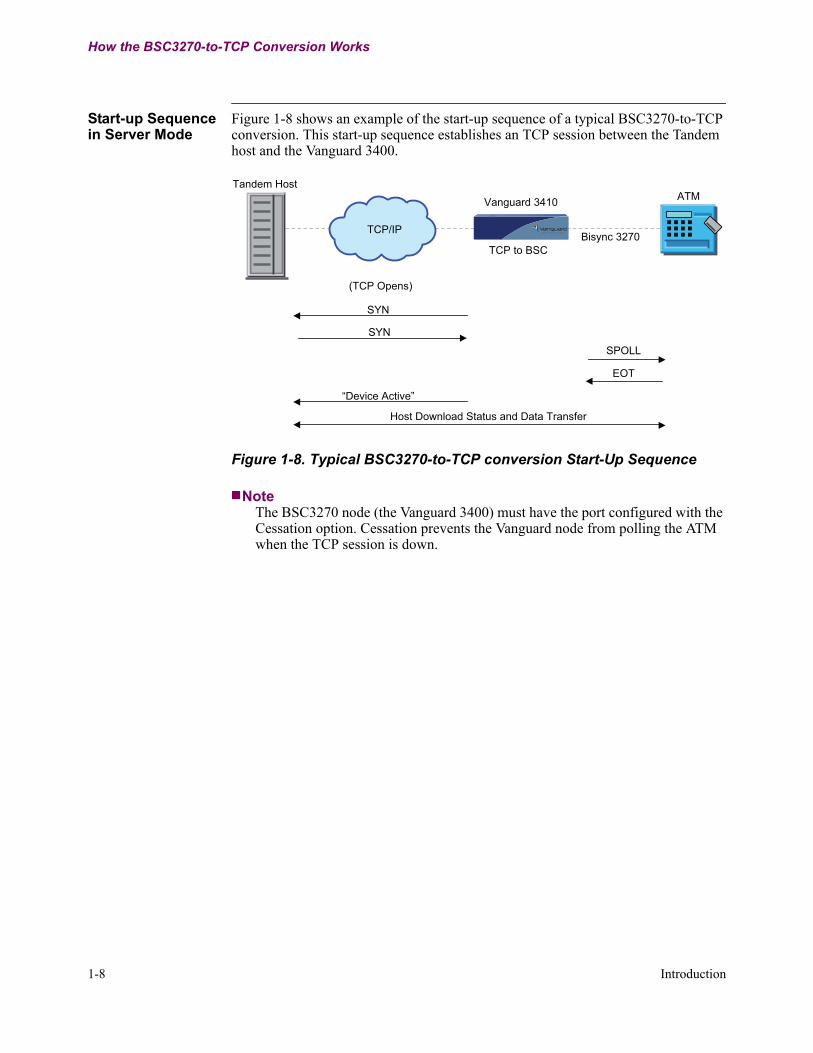
Start-up Sequence in Server Mode
Figure 1-8 shows an example of the start-up sequence of a typical BSC3270-to-TCP conversion. This start-up sequence establishes an TCP session between the Tandem host and the Vanguard 3400.
Figure 1-8. Typical BSC3270-to-TCP conversion Start-Up Sequence
NoteThe BSC3270 node (the Vanguard 3400) must have the port configured with the Cessation option. Cessation prevents the Vanguard node from polling the ATM when the TCP session is down.
SYN
SPOLL
EOT
Host Download Status and Data Transfer
“Device Active”
(TCP Opens)
SYN
Tandem Host
Vanguard 3410
TCP to BSC
ATM
Bisync 3270 TCP/IP
Introduction 1-9
T0290, Revision A Release 7.1
How the BSC3270-to-TCP Conversion Works
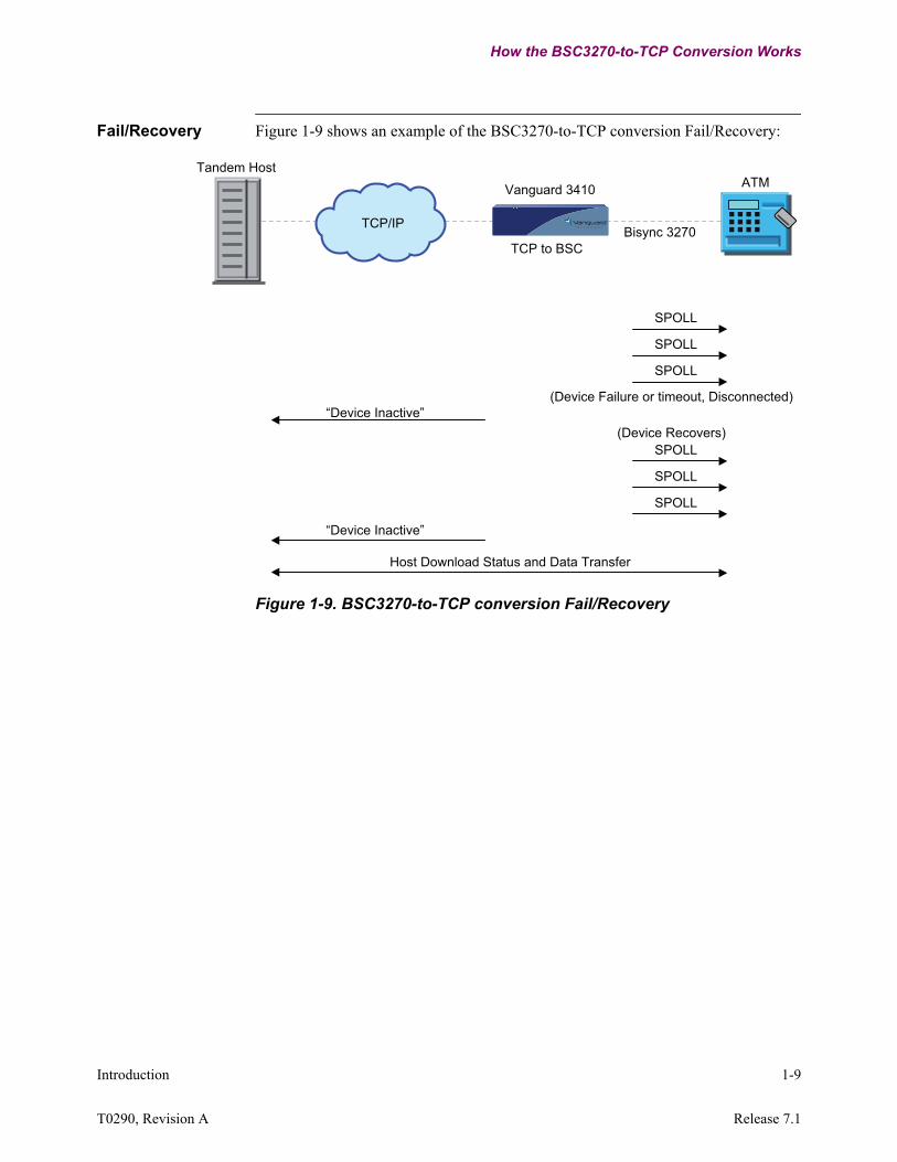
Fail/Recovery Figure 1-9 shows an example of the BSC3270-to-TCP conversion Fail/Recovery:
Figure 1-9. BSC3270-to-TCP conversion Fail/Recovery
“Device Inactive”
“Device Inactive”
SPOLL
Host Download Status and Data Transfer
SPOLL
SPOLL
SPOLL
SPOLL
SPOLL
Tandem Host
Vanguard 3410
TCP to BSC
ATM
Bisync 3270
(Device Failure or timeout, Disconnected)
(Device Recovers)
TCP/IP
1-10 Introduction
How the BSC3270-to-TCP Conversion Works
Device Enable in Server Mode
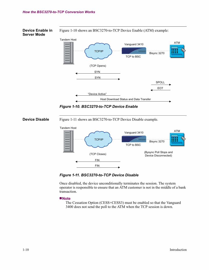
Figure 1-10 shows an BSC3270-to-TCP Device Enable (ATM) example:
Figure 1-10. BSC3270-to-TCP Device Enable
Device Disable Figure 1-11 shows an BSC3270-to-TCP Device Disable example.
Figure 1-11. BSC3270-to-TCP Device Disable
Once disabled, the device unconditionally terminates the session. The system operator is responsible to ensure that an ATM customer is not in the middle of a bank transaction.
NoteThe Cessation Option (CESS+CESS3) must be enabled so that the Vanguard 3400 does not send the poll to the ATM when the TCP session is down.
SYN
SPOLL
EOT
Host Download Status and Data Transfer
“Device Active”
(TCP Opens)
SYN
Tandem Host
Vanguard 3410
TCP to BSC
ATM
Bisync 3270 TCP/IP
FIN
FIN
(TCP Closes)(Bysync Poll Stops andDevice Disconnected)
Tandem Host
Vanguard 3410
TCP to BSC
ATM
Bisync 3270 TCP/IP
Introduction 1-11
T0290, Revision A Release 7.1
How the BSC3270-to-TCP Conversion Works
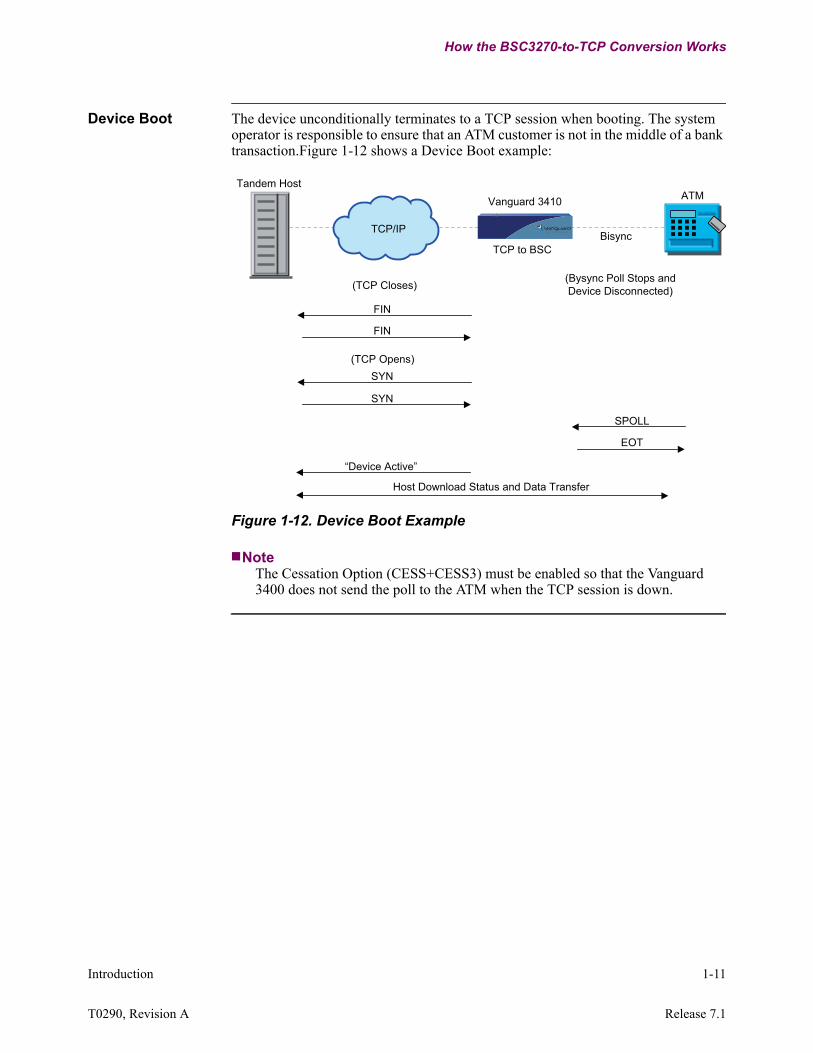
Device Boot The device unconditionally terminates to a TCP session when booting. The system operator is responsible to ensure that an ATM customer is not in the middle of a bank transaction.Figure 1-12 shows a Device Boot example:
Figure 1-12. Device Boot Example
NoteThe Cessation Option (CESS+CESS3) must be enabled so that the Vanguard 3400 does not send the poll to the ATM when the TCP session is down.
FIN
FIN
(TCP Closes)(Bysync Poll Stops andDevice Disconnected)
SYN
SYN
(TCP Opens)
SPOLL
EOT
Tandem Host
Vanguard 3410
TCP to BSC
ATM
BisyncTCP/IP
Host Download Status and Data Transfer
“Device Active”


Configuration 2-1
T0290, Revision A Release 7.1
Chapter 2Configuration
Overview
Introduction This chapter provides configuration procedures and examples for BSC3270-to-TCP/IP operation.
Before You Start Online HelpEntering a ? displays online Help for the current parameter option on the screen.Parameters with an asterisk (*)Parameters identified by an asterisk require a node boot for changes to the parameter to take effect.This chapter provides configuration examples and procedures for BSC 3270-to-TCP/IP conversion.

2-2 Configuration
Configuration Information and Examples
Configuration Information and Examples
Increase Parameters to Maximum Value for BSC-to-TCP
The guidelines below are required when using the BSC3270-to-TCP feature:The following Node Record Parameters need to be set to accommodate the maximum number of BSC3270 to TCP sessions that can be configured:
• Mnemonic Table Size• Quantity of DSP Devices• Maximum Simultaneous Calls
Local Dynamic Port Creation Heap Size needs to be configured Bisync and AS/400.
NoteWhen setting the Local Dynamic Port Creation Heap Size, refer to the Ease of Configuration information located in the Ease of Configuration and Enable Ease of Configuration sections of the Vanguard Applications Ware Basic Protocols Manual - Part No. T0106 (Click Applications Ware Protocols Documentation -> Basic->About this Manual). A copy of your current configuration files should be saved before changing the Local Dynamic Port Create Heap Size.
Configuration for BSC3270-to-TCP Operation
Introduction To set up a Vanguard for BSC3270-to-TCP operation, configure the following:• Node Record• Ethernet Port Record• Router (see Note 1 below• TCP (see Note 2 below)• BSC3270 Port Record (see Note 3 below)• BSC/DSP3270 Device Table (see Note 3 below)• TCP-to-BSC Conversion Record Configure
Note 1For details on configuring your node for LAN/WAN operation, refer to:
• Vanguard Configuration Basics Manual, (Part Number T0113)• Vanguard Router Basics Manual (Part No. T0100-01)• Vanguard IP Routing Basics Manual (Part No. T0100-03)
Note 2For details on configuring your node for TCP operation, refer to:
• Vanguard TCP/Telnet Basic Protocols Manual (Part No. T0106-07)
Note 3Only the parameters required for BSC3270-to-TCP operation are discussed in this manual. For details on configuring your node for BSC3270 operation, refer to:
• Vanguard IBM BSC 3270 Manual (Part No. T0101-03)

Configuration 2-3
T0290, Revision A Release 7.1
Configuration Information and Examples
Configuring a NodeFollow the steps in the table below to configure the Node Record parameters:
Configuration Menu
Figure 2-1 below is a sample Configuration Menu:
Figure 2-1. Sample Configuration Menu
Step Action Result1 Select Configure from the CTP
Main menu.The Configure menu displays.
Node: TCPBSC Address: 2706 Date: 14-AUG-2008 Time: 13:20:38Menu: Configure Path: (Main.6)
1. Node 19. Configure LAN Connections 2. Port 20. Alarms Throttling 3. Configure Network Services 21. Configure Router 4. Inbound Call Translation Table 22. LLC to SDLC Tables 5. Outbound Call Translation Table 23. TCP 6. PAD Prompt Table 24. PPP/MLP Authentication Parameter 7. Software Key Table 25. PPP/MLP Profiles 8. Calling Addr Translation Table 26. Configure SPFM Connection Table 9. NUI/Password Table 27. ToW Table 10. PAD Profile Table 28. AT Dialer Profile 11. Remote PAD Parameter Table 29. T1/E1 Interface 12. CUD based Addr Translation Table 30. Configure SNMP 13. Node to node download 31. Virtual Port Mapping Table 14. BSC/DSP3270 Device Table 32. Configure TFTP Server 15. SDLC Port Stations 33. TCP to BSC Conv Record Configure 16. FRI Stations 17. Configure Bridge 18. Configure Network Security
#Enter Selection:
2-4 Configuration
Configuration Information and Examples
Configuring Node Record
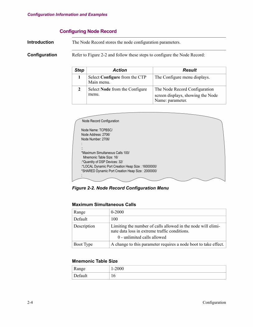
Introduction The Node Record stores the node configuration parameters.
Configuration Refer to Figure 2-2 and follow these steps to configure the Node Record:
Figure 2-2. Node Record Configuration Menu
Step Action Result1 Select Configure from the CTP
Main menu.The Configure menu displays.
2 Select Node from the Configure menu.
The Node Record Configurationscreen displays, showing the Node Name: parameter.
Node Record Configuration
Node Name: TCPBSC/Node Address: 2706/Node Number: 2706/:::*Maximum Simultaneous Calls 100/
Mnemonic Table Size: 16/:*Quantity of DSP Devices: 32/:*LOCAL Dynamic Port Creation Heap Size : 16000000/*SHARED Dynamic Port Creation Heap Size : 2000000/:
Maximum Simultaneous CallsRange 0-2000Default 100Description Limiting the number of calls allowed in the node will elimi-
nate data loss in extreme traffic conditions. 0 - unlimited calls allowed
Boot Type A change to this parameter requires a node boot to take effect.
Mnemonic Table Size Range 1-2000Default 16

Configuration 2-5
T0290, Revision A Release 7.1
Configuration Information and Examples
Description Maximum permitted number of Mnemonic Table entries. The CMEM value of this parameter determines the maximum entry number for new CMEM table entries. It may be neces-sary to increase this size parameter value before adding new table entries.
Boot Type A change to this parameter requires a node boot to take effect.
Mnemonic Table Size (continued)
Quantity of DSP DevicesRange 1-1024Default 32Description Maximum configured number of DSP type devices on this
node.For example BSC3270, BSTD, IBM2260 all use DSP devices.
Boot Type A change to this parameter requires a node boot to take effect.
LOCAL Dynamic Port CreationRange 16384-16000000Default 16000000Description Select size of the special local memory pool dedicated for
dynamic port deletion and creation.Set size to 0 to disable the pool.
Boot Type A change to this parameter requires a node boot to take effect.
SHARED Dynamic Port CreationRange 16384-16000000Default 2000000Description Select size of the special shared memory pool dedicated for
dynamic port deletion and creation.This entry is ignored if the local memory pool size is zero.
Boot Type A change to this parameter requires a node boot to take effect.
2-6 Configuration
Configuration Information and Examples
Configuring Port Records
Introduction Port Records store the port configuration parameters, with each active port having a separate record. Active port number (location) and port type must be defined before you configure the remaining Port Record parameters.
Configuration Follow these steps to configure the Port Records:
Configuring the Ethernet Port Record
Ethernet Port Record Parameters
The Ethernet Port record contains these parameters:
Step Action Result1 Select Configure from the
CTP Main menu.The Configure menu displays.
2 Select Port from the Con-figure menu.
The Port Number parameter displays.
3 At the prompt, enter the number of the port you want to configure and press Return.
The parameters are successively dis-played.
NoteWhen an asterisk appears beside a param-eter in a record, a Node Boot is needed for any changes to that parameter to take effect.
Port NumberRange 23 or 24Default 23Description Enter the number of the port to configure. This number is the
Port Record reference number and represents both physical and virtual ports. Physical ports are located at the front and rear of the hardware chassis.
Port TypeRange NULL, ETHDefault ETHDescription Specify the type of port you are configuring:
• NULL - NULL port type• ETH - Ethernet port type
Boot Type A change to this parameter requires a node boot to take effect.

Configuration 2-7
T0290, Revision A Release 7.1
Configuration Information and Examples
Port MAC AddressRange 00-00-00-00-00-00 to FE-FF-FF-FF-FF-FFDefault 00-00-00-00-00-00Description Specifies the MAC address of the LAN port. The entered
value of 00-00-00-00-00-00 is replaced by the Burned in Address (BIA) if the LAN hardware is present.
Boot Type A change to this parameter requires a node boot to take effect.
Transmit Queue LimitRange 20 to 500Default 50Description Specifies the maximum number of frames that can be queued
on the LAN transmitter before any frames are dropped.
Bridge Link Number Range 1 to 5Default 1Description Specifies the bridge link number associated with the LAN
port. The corresponding bridge link record must be configured under the bridge configuration menu.
Router Interface NumberRange 1-50Default 1Description Specifies the router interface number associated with this
LAN port.
Port Operating ModeRange AUTO, 1000FD, 100FD, 100HD, 10FD, 10HDDefault AUTODescription Specifies whether this LAN port runs in 1000Mbit Full-
Duplex,100Mbit Full-Duplex, 100Mbit Half-Duplex, 10Mbit Full-Duplex,10Mbit Half-Duplex, or Auto-Negotiation mode.
NoteVanguard 7300 Series - Release 6.4 and greater software supports1000FD on ports 101 and 103 using the IBM750FX CPU card.ETH1 is port 101, ETH2 is port 103. Port 102 is the COM port.
2-8 Configuration
Configuration Information and Examples
Configuring TCP to BSC Tables
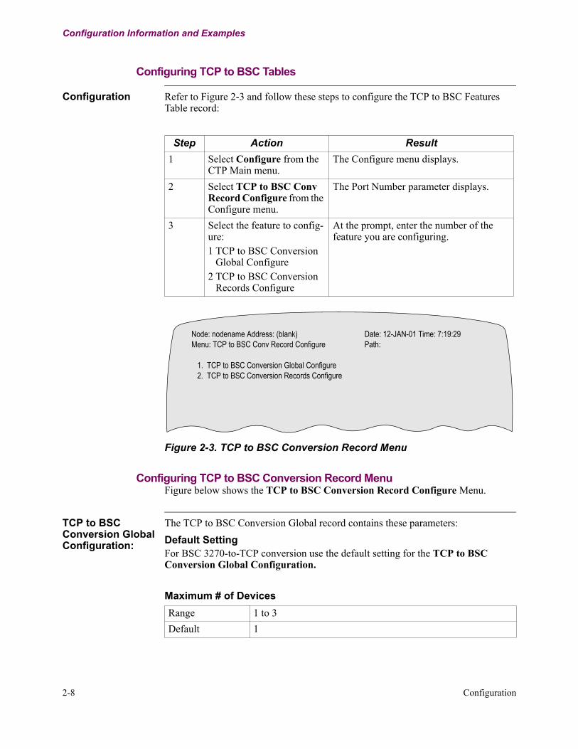
Configuration Refer to Figure 2-3 and follow these steps to configure the TCP to BSC Features Table record:
Figure 2-3. TCP to BSC Conversion Record Menu
Configuring TCP to BSC Conversion Record MenuFigure below shows the TCP to BSC Conversion Record Configure Menu.
TCP to BSC Conversion Global Configuration:
The TCP to BSC Conversion Global record contains these parameters:Default SettingFor BSC 3270-to-TCP conversion use the default setting for the TCP to BSC Conversion Global Configuration.
Step Action Result1 Select Configure from the
CTP Main menu.The Configure menu displays.
2 Select TCP to BSC Conv Record Configure from the Configure menu.
The Port Number parameter displays.
3 Select the feature to config-ure:1 TCP to BSC Conversion
Global Configure2 TCP to BSC Conversion
Records Configure
At the prompt, enter the number of the feature you are configuring.
Node: nodename Address: (blank) Date: 12-JAN-01 Time: 7:19:29Menu: TCP to BSC Conv Record Configure Path:
1. TCP to BSC Conversion Global Configure 2. TCP to BSC Conversion Records Configure
Maximum # of Devices Range 1 to 3Default 1

Configuration 2-9
T0290, Revision A Release 7.1
Configuration Information and Examples
Description Maximum number of ATMs to be configured.Note
This number must be at least the number of ATMs to be con-figured.
Maximum # of Devices (continued)
TCP Read and Write buffer sizeRange 100-65000Default 2048Description This parameter sets the size of read and write buffers posted to
TCP by TCP BSC.
TCPBSC Window SizeRange 1-63Default 15Description The window size that TCPBSC maintains with its peer.
TCP Maximum Segment SizeRange 1-2048Default 536Description This parameter sets the maximum size of the segments sent
out by TCP.
TCP Keep alive timerRange Enabled,DisabledDefault EnabledDescription Turn ON/OFF the TCP keep alive timer. If it is enabled, TCP
sends keep alive packets every 1 minute.
Public Access TCP Port NumberRange 1-65535Default 0Description This is the TCP port number that the TCPBSC Server will
accept PUBLIC connections on.

2-10 Configuration
Configuration Information and Examples
TCP to BSC Conversion Records Configuration:
The TCP to BSC Conversion record contains these parameters:
Entry NumberRange 1-3Default 1Description Entry number used to reference this table record.
TCP RoleRange CLIENT,SERVERDefault CLIENTDescription CLIENT - TCPBSC is client
SERVER - TCPBSC is server
Destination IP AddressRange A valid IP address in dotted notationDefault 0.0.0.0Description (Client only) Specifies the destination IP address used for ses-
sion establishment.
Destination Port NumberRange 256-65535Default 3000Description (Client only) Specifies the destination TCP port number used
for session establishment.
Source Interface NumberRange 0-36Default 0Description Specifies the Interface Number referring to the source IP
Address. Interface 0 refers to Internal IP Address. In Server role, Interface 0 or a LAN interface is ignored, but a WAN interface may be specified only to allow the remote client to access this node.
Configuration 2-11
T0290, Revision A Release 7.1
Configuration Information and Examples
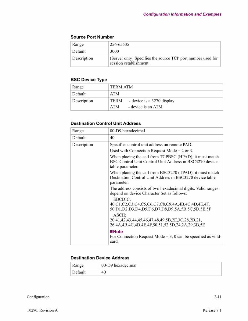
Source Port Number Range 256-65535Default 3000Description (Server only) Specifies the source TCP port number used for
session establishment.
BSC Device TypeRange TERM,ATMDefault ATMDescription TERM - device is a 3270 display
ATM - device is an ATM
Destination Control Unit Address Range 00-D9 hexadecimalDefault 40Description Specifies control unit address on remote PAD.
Used with Connection Request Mode = 2 or 3.When placing the call from TCPBSC (HPAD), it must match BSC Control Unit Control Unit Address in BSC3270 device table parameter.When placing the call from BSC3270 (TPAD), it must match Destination Control Unit Address in BSC3270 device table parameter.The address consists of two hexadecimal digits. Valid ranges depend on device Character Set as follows: EBCDIC: 40,C1,C2,C3,C4,C5,C6,C7,C8,C9,4A,4B,4C,4D,4E,4F, 50,D1,D2,D3,D4,D5,D6,D7,D8,D9,5A,5B,5C,5D,5E,5F ASCII: 20,41,42,43,44,45,46,47,48,49,5B,2E,3C,28,2B,21, 26,4A,4B,4C,4D,4E,4F,50,51,52,5D,24,2A,29,3B,5E
NoteFor Connection Request Mode = 3, 0 can be specified as wild-card.
Destination Device Address Range 00-D9 hexadecimalDefault 40

2-12 Configuration
Configuration Information and Examples
Description Specifies device address on remote PAD.Used with Connection Request Mode = 2 or 3.When placing the call from TCPBSC (HPAD), it must match BSC Device Address in BSC3270 device table parameter.When placing the call from BSC3270 (TPAD), it must match Des-tinationDevice Address in BSC3270 device table parameter. This address consists of two hexadecimal digits.Valid ranges depend on device.Character Set as follows: EBCDIC: 40,C1,C2,C3,C4,C5,C6,C7,C8,C9,4A,4B,4C,4D,4E,4F,50,D1,D2,D3,D4,D5,D6,D7,D8,D9,5A,5B,5C,5D,5E,5F ASCII: 20,41,42,43,44,45,46,47,48,49,5B,2E,3C,28,2B,21,26,4A,4B,4C,4D,4E,4F,50,51,52,5D,24,2A,29,3B,5E
Destination Device Address (continued)
TCP Host Applications Range BASE24,EPOCDefault BASE24Description Type of TCP Host applications supported for this session
3270 Command/WCC inserted in outbound MessageRange 0000-FFFF hexadecimalDefault F1C2

Configuration 2-13
T0290, Revision A Release 7.1
Configuration Information and Examples
Description Use only for data containing no 3270 command and WCC on outbound LU type 0.Specifies the 3270 Write Command and the WCC to be inserted at beginning of each outbound RU.The 2 hexadecimal or ascii digits for the 3270 Command as follows: 'F1' or '31' - Write 'F5' or '35' - Erase Write '6F' or '3F' - Erase All UnprotectedThe 2 hexadecimal digits for the WCC as follows: 'C2' - Restore input key operation 'C5' - Restore key operation and reset MDT bits in device buffer '0000' - nothing will be inserted in RUExample: 'F1C2' - Write on screen and restore input keys operation 'F5C5' - Erase and Write on screen, restore input keys operation, and reset MDT bits in device buffer.
3270 Command/WCC inserted in outbound Message
Autocall MnemonicRange 0-8 alphanumeric characters, use the space character to blank
fieldDefault (blank)Description This mnemonic references the remote X.25 address which
will be auto-called.If blank, then autocalling is disabled, and the other end should initiate the call.
EBCDIC/ASCII TranslationRange Enabled,DisabledDefault EnabledDescription
TCPBSC Options Range NONE,NHOSTDA,TCPDBG,DSPDBG,TSTAUTOLOGDefault NONE
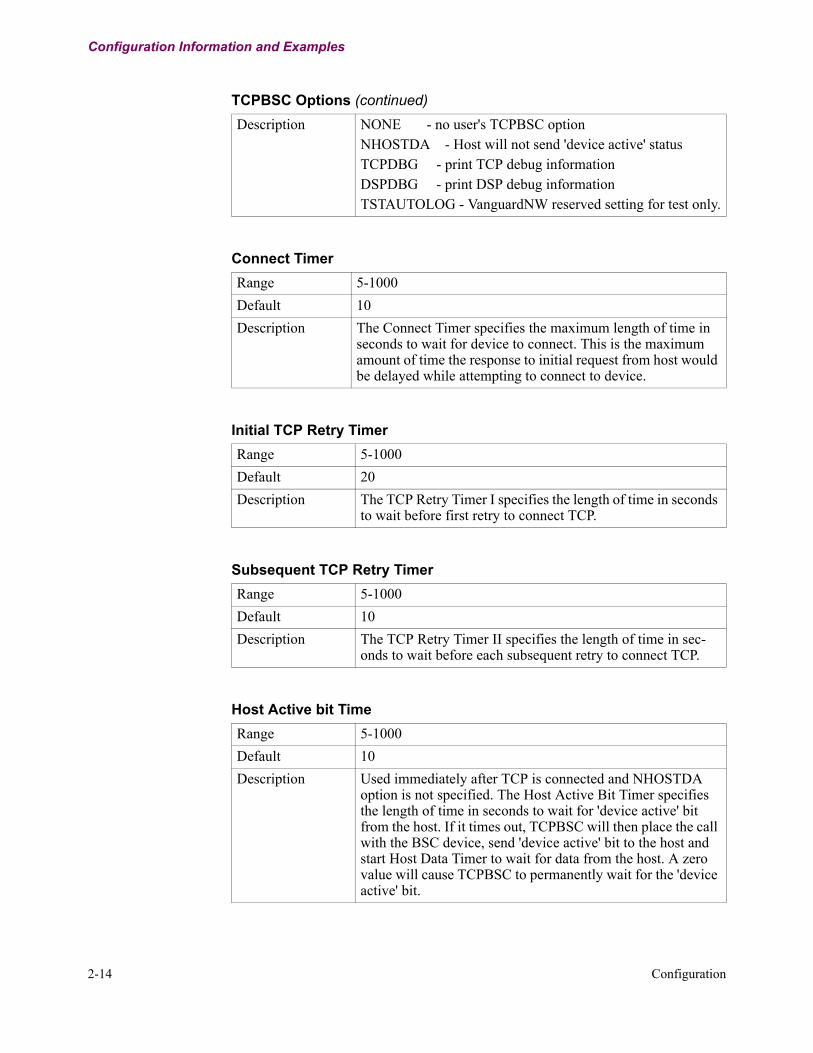
2-14 Configuration
Configuration Information and Examples
Description NONE - no user's TCPBSC optionNHOSTDA - Host will not send 'device active' statusTCPDBG - print TCP debug informationDSPDBG - print DSP debug informationTSTAUTOLOG - VanguardNW reserved setting for test only.
TCPBSC Options (continued)
Connect TimerRange 5-1000Default 10Description The Connect Timer specifies the maximum length of time in
seconds to wait for device to connect. This is the maximum amount of time the response to initial request from host would be delayed while attempting to connect to device.
Initial TCP Retry TimerRange 5-1000Default 20Description The TCP Retry Timer I specifies the length of time in seconds
to wait before first retry to connect TCP.
Subsequent TCP Retry TimerRange 5-1000Default 10Description The TCP Retry Timer II specifies the length of time in sec-
onds to wait before each subsequent retry to connect TCP.
Host Active bit Time Range 5-1000Default 10Description Used immediately after TCP is connected and NHOSTDA
option is not specified. The Host Active Bit Timer specifies the length of time in seconds to wait for 'device active' bit from the host. If it times out, TCPBSC will then place the call with the BSC device, send 'device active' bit to the host and start Host Data Timer to wait for data from the host. A zero value will cause TCPBSC to permanently wait for the 'device active' bit.
Configuration 2-15
T0290, Revision A Release 7.1
Configuration Information and Examples
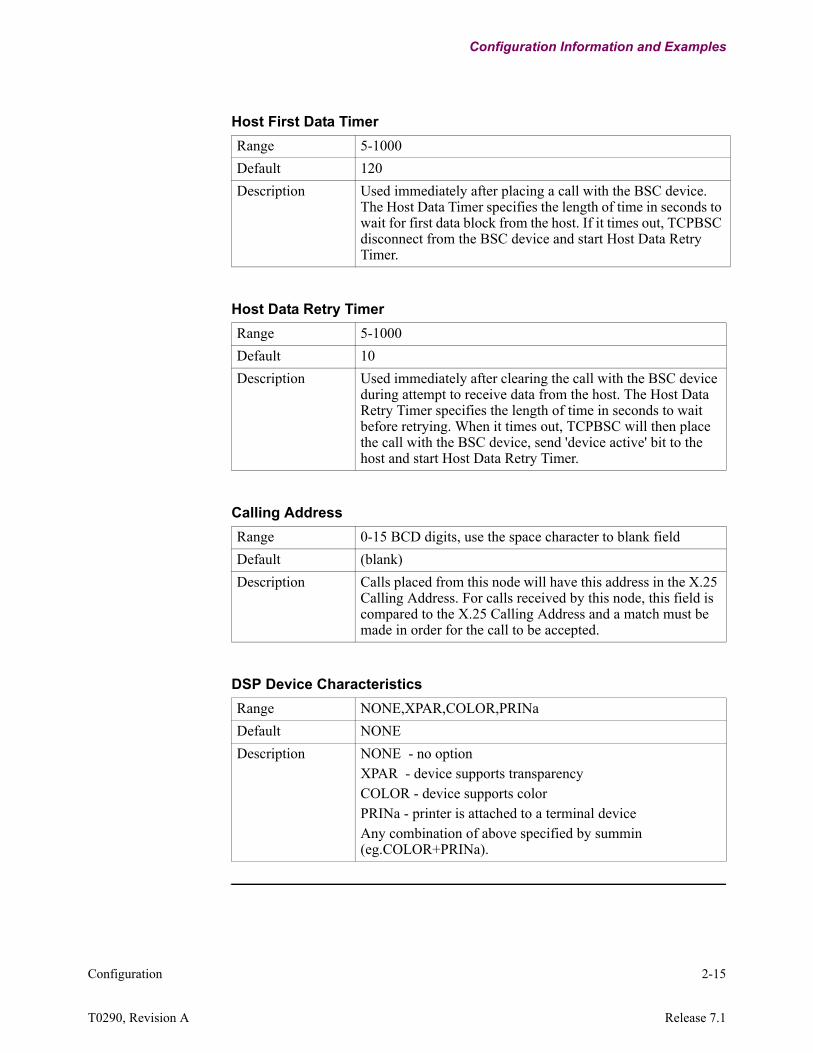
Host First Data TimerRange 5-1000Default 120Description Used immediately after placing a call with the BSC device.
The Host Data Timer specifies the length of time in seconds to wait for first data block from the host. If it times out, TCPBSC disconnect from the BSC device and start Host Data Retry Timer.
Host Data Retry TimerRange 5-1000Default 10Description Used immediately after clearing the call with the BSC device
during attempt to receive data from the host. The Host Data Retry Timer specifies the length of time in seconds to wait before retrying. When it times out, TCPBSC will then place the call with the BSC device, send 'device active' bit to the host and start Host Data Retry Timer.
Calling AddressRange 0-15 BCD digits, use the space character to blank fieldDefault (blank)Description Calls placed from this node will have this address in the X.25
Calling Address. For calls received by this node, this field is compared to the X.25 Calling Address and a match must be made in order for the call to be accepted.
DSP Device Characteristics Range NONE,XPAR,COLOR,PRINaDefault NONEDescription NONE - no option
XPAR - device supports transparencyCOLOR - device supports colorPRINa - printer is attached to a terminal deviceAny combination of above specified by summin (eg.COLOR+PRINa).
2-16 Configuration
Configuration Information and Examples
Configuring BSC3270
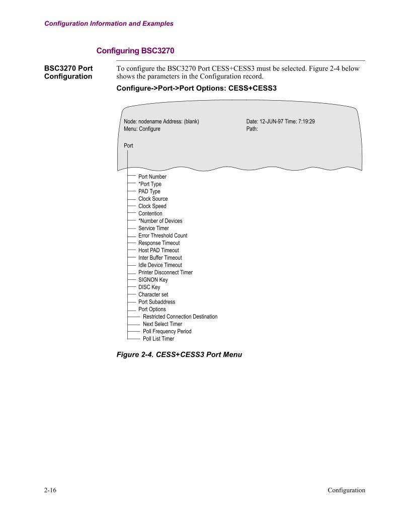
BSC3270 Port Configuration
To configure the BSC3270 Port CESS+CESS3 must be selected. Figure 2-4 belowshows the parameters in the Configuration record.Configure->Port->Port Options: CESS+CESS3
Figure 2-4. CESS+CESS3 Port Menu
Port Number*Port TypePAD TypeClock SourceClock SpeedContention*Number of DevicesService TimerError Threshold CountResponse TimeoutHost PAD TimeoutInter Buffer TimeoutIdle Device TimeoutPrinter Disconnect TimerSIGNON KeyDISC KeyCharacter setPort SubaddressPort Options
Restricted Connection DestinationNext Select TimerPoll Frequency PeriodPoll List Timer
Node: nodename Address: (blank) Date: 12-JUN-97 Time: 7:19:29Menu: Configure Path:
Port
Configuration 2-17
T0290, Revision A Release 7.1
Configuration Information and Examples
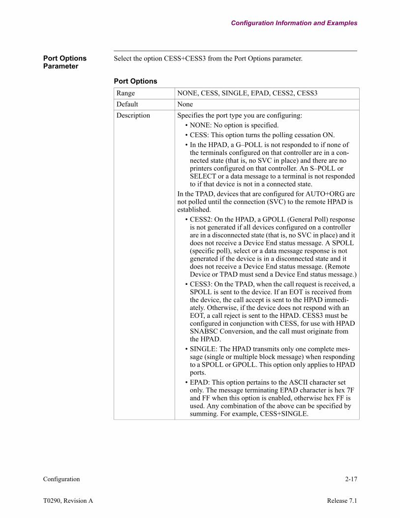
Port Options Parameter
Select the option CESS+CESS3 from the Port Options parameter.
Port OptionsRange NONE, CESS, SINGLE, EPAD, CESS2, CESS3Default NoneDescription Specifies the port type you are configuring:
• NONE: No option is specified.• CESS: This option turns the polling cessation ON.• In the HPAD, a G–POLL is not responded to if none of
the terminals configured on that controller are in a con-nected state (that is, no SVC in place) and there are no printers configured on that controller. An S–POLL or SELECT or a data message to a terminal is not responded to if that device is not in a connected state.
In the TPAD, devices that are configured for AUTO+ORG are not polled until the connection (SVC) to the remote HPAD is established.
• CESS2: On the HPAD, a GPOLL (General Poll) response is not generated if all devices configured on a controller are in a disconnected state (that is, no SVC in place) and it does not receive a Device End status message. A SPOLL (specific poll), select or a data message response is not generated if the device is in a disconnected state and it does not receive a Device End status message. (Remote Device or TPAD must send a Device End status message.)
• CESS3: On the TPAD, when the call request is received, a SPOLL is sent to the device. If an EOT is received from the device, the call accept is sent to the HPAD immedi-ately. Otherwise, if the device does not respond with an EOT, a call reject is sent to the HPAD. CESS3 must be configured in conjunction with CESS, for use with HPAD SNABSC Conversion, and the call must originate from the HPAD.
• SINGLE: The HPAD transmits only one complete mes-sage (single or multiple block message) when responding to a SPOLL or GPOLL. This option only applies to HPAD ports.
• EPAD: This option pertains to the ASCII character set only. The message terminating EPAD character is hex 7F and FF when this option is enabled, otherwise hex FF is used. Any combination of the above can be specified by summing. For example, CESS+SINGLE.

2-18 Configuration
Configuration Information and Examples
BSC/DSP3270 Configuration
Figure 2-5 below is a sample Configure Menu. SPEOT must be selected in the Device Control parameter.Configure->BSC/DSP3270 Device Table->Device Control: SPEOT
Figure 2-5. Sample Configuration Menu
Device Option Parameter
Select SPEOT from the Device Option parameter in the BSC/DSP3270 Device Table.
Node: Address: Date: Time:Menu: Configure Path: (Main.6)
1. Node 19. Software Key Table2. Port 20. Configure Router3. Configure Network Services 21. LLC to SDLC Tables4. Inbound Call Translation Table 22. DORA Record5. Outbound Call Translation Table 23. TCP6. PAD Prompt Table 24. PPP Parameters7. Calling Addr Translation Table 25. PPP Profiles8. CUD based Addr Translation Table 26. Configure SPFM Connection Table9. NUI/Password Table 27. ToW Table10. PAD Profile Table 28. (reserved)11. Remote PAD Parameter Table 29. (reserved)12. BSC/DSP3270 Device Table 30. Configure SNMP13. Node to Node Download14. SDLC Port Stations15. FRI Stations16. XDLC Port Stations17. Configure Bridge18. Configure LAN Connections-Enter Selection:
Device Control Range NONE, GPOLL, PSPOLL, SPOLL, MSPOLL, NSERV,
NSTAT, RVI, SPEOT, SPEND, NCMDDefault None

Configuration 2-19
T0290, Revision A Release 7.1
Configuration Information and Examples
Description Specifies device control:• NONE: No device control parameter set.• GPOLL: Device is only polled by General Polls (TPAD
only).• PSPOLL: Periodic specific polling of a device (TPAD
only).• SPOLL: Forced specific polling of a device (TPAD only).• MSPOLL: Forced specific polling of a device, except
when the controller is down (TPAD only).• NSERV: No service messages are sent to the device
(TPAD only).• NSTAT: Disables the generation of dummy DEVICE
END status messages.• RVI: Forces TPAD to send RVI as an ACK for terminal
text/ status messages terminated with ETB or ETX (TPAD only).
• SPEOT: SEL-ACK-TEXT-EOT-POLL-EOT or SEL-RVI-POLL-
• EOT message exchanges between the TPAD and the con-troller disconnects the device’s session to prevent a lockup condition due to a faulty controller (TPAD only).
• SPEND: SPOLL is sent to every Service Timer Interval when the TPAD is flow controlled, that is, TPAD received WACK.
• NCMD: Prevents the HPAD from checking for ESC and CMD codes in messages from the host. Consequently, the LCM flag is never sent in DSP messages to the TPAD. Printer devices are not supported.
NoteAny combination of the above may be specified by summing, for example, GPOLL+SPOLL. GPOLL overrides SPOLL if both are selected; this situation is not recommended. Devices under a COMMON CU ADDRESS must have identical Poll-ing methods. For example, if CU40 has 4 devices, all devices must be GPOLL, SPOLL, or neither
Device Control (continued)

2-20 Configuration
Configuration Examples
Configuration Examples
Application #1 Figure 2-6 and Figure 2-7 show how Node100 and Node 200 are configured to connect Base24 Host Server with BSC ATM Client in WAN environment. Note that TCP-to-BSC Conversion is in Node200 where Router and TCP-to-BSC Conversion Record are configured to use Internal Address as the source IP address through Source Interface Number 0 (internal IP address.
Figure 2-6. Example of Base24 Remote Client Application 1
(Remote Client)
Data Center
HP (Tandem) Server
Port 100Int # 5
LCON # 1144.33.5.x/24
144.33.4.x/24
Port 1 (BSC327)
Node100
T1 MLPPP
Port 5Int # 1
.2
Port 100Int # 5.2
Port 7 (T1)
ATM
BSC3270
.1
.1
Port 7 (T1)
Host Base 24 ApplicationVanguard 3410Vanguard 340E
Node200
Node RecordNode Name: Node100Node Address:100Node Number:100
Port Record[5] *Port Type: ETH[5] *Port MAC Address: 00-00-00-00-00-00[5] Transmit Queue Limit: 500[5] *Bridge Link Number: 1[5] *Router Interface Number: 1
[100] *Port Type: PPP/[100] *Stacking Support: NONE/[100] *Line Interface: T1E1/[100] *PPP Operation: Multilink/[100] Alternate CHAP Name Control: Disabled/[100] *Maximum Number of Config Request Attempts: 0
Router Interface States[1] *Interface State : Enabled[5] *Interface State : Enabled
IP ParametersAccess Control:DisabledRIP Enable:DisabledDefault Gateway:144.33.5.2
IP Interface[1]Interface Number:1[1]IP Address :144.33.4.2[1]IP Address Mask:255.255.255.0
[5]Interface Number:5[5]IP Address :144.33.5.1[5]IP Address Mask:255.255.255.0
LAN Connection Table[1] *Lan Forwarder Type: ROUT[1] Lan Connection Type: PT_TO_PT[1] *Router Interface Number: 5[1] Encapsulation Type: RFC1294/1661
PVC Setup Table[1] *Source: LCON-1[1] *Destination: MLPPP-1
T1/E1 Interface[1] *Interface Type: T1[1] *Format Type: Channelize[1] Line framing Type: ESF[1] Line Coding Type: B8ZS[1] Transmit Clock: INT
Virtual Port Mapping Table[1] *Virtual Port Type: TDM-DATA[1] *Virtual Port Number: 100[1] *Interface Number: 1[1] *Time Slot: 1-24[1] *DS0 Rate: 64K
PPP/MLP Profiles[1] Authentication Protocol: NONE[1] Network Protocols: IP[1] IPCP options: ADDR[1] Local IP Address: 144.33.5.1[1] Remote IP Address: 144.33.5.2[1] *Dedicated Links: 100

Configuration 2-21
T0290, Revision A Release 7.1
Configuration Examples
Figure 2-7. Example of Base24 Remote Client Application 2
(Remote Client)
Data Center
HP (Tandem) Server
Port 100Int # 5
LCON # 1144.33.5.x/24
144.33.4.x/24
Port 1 (BSC327)
Node100
T1 MLPPP
Port 5Int # 1
.2
Port 100Int # 5.2
Port 7 (T1)
ATM
BSC3270
.1
.1
Port 7 (T1)
Host Base 24 ApplicationVanguard 3410Vanguard 340E
Node200
BSC/DSP3270 Device[1]BSC Control Unit Address:C1[1]BSC Device Address:40[1]DSP Device Type:TERM[1]DSP Control:NONE[1]Device Control:SPOLL[1]Device Option:NONE[1]DSP Device Characteristics:XPAR[1]DSP Device Format Size:480[1]DSP Character Set Capability:NONE[1]DSP Application Identifier:0[1]Connection Request Mode:2[1]Destination Control Unit Address:C1[1]Destination Device Address:40
TCP to BSC Conversion Global ConfigureMaximum # of Devices: 1/TCP Read and Write buffer size: 2048/TCPBSC Window Size: 15/TCP Maximum Segment Size: 536/TCP Keep alive timer: Enabled/Public Access TCP Port Number: 0/
Port Record[1]Port Type: BSC3270[1]Interface Type:V.24[1]V.24 Interface Option:RI[1]PAD Type:TPAD[1]Clock Source:INT[1]Clock Speed:9600[1]Contention:FDX[1]Connection type:SIMP[1]*Number of Devices:1[1]Port Options:CESS3
[100] *Port Type: PPP/[100] *Stacking Support: NONE/[100] *Line Interface: T1E1/[100] *PPP Operation: Multilink/[100] Alternate CHAP Name Control: Disabled/[100] *Maximum Number of Config Request
Attempts: 0Router Interface States[5] *Interface State : Enabled[6] *Interface State : Enabled
IP ParametersInternal IP Address:144.33.4.2Internal Net Mask:255.255.255.0Access Control:DisabledRIP Enable:DisabledDefault Gateway:144.33.5.1
Mnemonic Table[1]Mnemonic Name:tcpbsc01[1]Call Parameters:20001
LAN Connection Table[1] *Lan Forwarder Type: ROUT[1] Lan Connection Type: PT_TO_P[1] *Router Interface Number: 5[1] Encapsulation Type: RFC1294/16
*NOTE: Use Internal IP Address as a source IP address
Node RecordNode Name: Node200Node Address:200
Node Number:200
IP Interface[5]Interface Number:5[5]IP Address :144.33.5.2[5]IP Address Mask:255.255.255.0
PVC Setup Table[1] *Source: LCON-1[1] *Destination: MLPPP-1
T1/E1 Interface[1] *Interface Type: T1[1] *Format Type: Channelize[1] Line framing Type: ESF[1] Line Coding Type: B8ZS[1] Transmit Clock: REC
Virtual Port Mapping Table[1] *Virtual Port Type: TDM-DATA[1] *Virtual Port Number: 100[1] *Interface Number: 1[1] *Time Slot: 1-24[1] *DS0 Rate: 64K
PPP/MLP Profiles[1] Authentication Protocol: NONE[1] Network Protocols: IP[1] IPCP options: ADDR[1] Local IP Address: 0.0.0.0[1] Remote IP Address: 0.0.0.0[1] *Dedicated Links: 100
TCP to BSC Conversion Record [1]TCP Role:CLIENT[1]Destination IP Address:144.33.4.1[1]Destination Port Number:1024[1]Source Interface Number:0*[1]BSC Device Type:ATM[1]Destination Control Unit [1]Address:C1[1]Destination Device Address:40[1]3270 Command/WCC inserted in outbound
Message:0000[1]Autocall Mnemonic:tcpbsc01[1]EBCDIC/ASCII Translation:Enabled[1]Host Applications :BASE24[1]TCPBSC Options:NONE

2-22 Configuration
Configuration Examples
Application #2 Figure 2-8 shows Router and TCP-to-BSC Conversion Record in Node 200 configured to use Source Interface Number 6 as the source IP address.
Figure 2-8. Example of Base24 Remote Client Router and TCP-to-BSC Conversion Record
BSC/DSP3270 Device[1]BSC Control Unit Address:C1[1]BSC Device Address:40[1]DSP Device Type:TERM[1]DSP Control:NONE[1]Device Control:SPOLL[1]Device Option:NONE[1]DSP Device Characteristics:XPAR[1]DSP Device Format Size:480[1]DSP Character Set Capability:NONE[1]DSP Application Identifier:0[1]Connection Request Mode:2[1]Destination Control Unit Address:C1[1]Destination Device Address:40
TCP to BSC Conversion Global ConfigureMaximum # of Devices: 1/TCP Read and Write buffer size: 2048/TCPBSC Window Size: 15/TCP Maximum Segment Size: 536/TCP Keep alive timer: Enabled/Public Access TCP Port Number: 0/
Port Record[1]Port Type: BSC3270[1]Interface Type:V.24[1]V.24 Interface Option:RI[1]PAD Type:TPAD[1]Clock Source:INT[1]Clock Speed:9600[1]Contention:FDX[1]Connection type:SIMP[1]*Number of Devices:1[1]Port Options:CESS3
[100] *Port Type: PPP/[100] *Stacking Support: NONE/[100] *Line Interface: T1E1/[100] *PPP Operation: Multilink/[100] Alternate CHAP Name Control: Disabled/[100] *Maximum Number of Config Request Attempts: 0
Router Interface States[5] *Interface State : Enabled[6] *Interface State : Enabled
IP ParametersAccess Control:DisabledRIP Enable:DisabledDefault Gateway:144.33.5.1IP Interface
[5]Interface Number:5[5]IP Address :144.33.5.2[5]IP Address Mask:255.255.255.0
[6]Interface Number:6[6]IP Address :144.33.4.2[6]IP Address Mask:255.255.255.0
Mnemonic Table[1]Mnemonic Name:tcpbsc01[1]Call Parameters:20001
LAN Connection Table[1] *Lan Forwarder Type: ROUT[1] Lan Connection Type: PT_TO_P[1] *Router Interface Number: 5[1] Encapsulation Type: RFC1294/16
PVC Setup Table[1] *Source: LCON-1[1] *Destination: MLPPP-1
T1/E1 Interface[1] *Interface Type: T1[1] *Format Type: Channelize[1] Line framing Type: ESF[1] Line Coding Type: B8ZS[1] Transmit Clock: REC
Virtual Port Mapping Table[1] *Virtual Port Type: TDM-DATA[1] *Virtual Port Number: 100[1] *Interface Number: 1[1] *Time Slot: 1-24[1] *DS0 Rate: 64K
PPP/MLP Profiles[1] Authentication Protocol: NONE[1] Network Protocols: IP[1] IPCP options: ADDR[1] Local IP Address: 0.0.0.0[1] Remote IP Address: 0.0.0.0[1] *Dedicated Links: 100
Node RecordNode Name: Node200Node Address:200Node Number:200
TCP to BSC Conversion Record [1]TCP Role:CLIENT[1]Destination IP Address:144.33.4.1[1]Destination Port Number:1024[1]Source Interface Number:6[1]BSC Device Type:ATM[1]Destination Control Unit Address:C1[1]Destination Device Address:40[1]3270 Command/WCC inserted in outbound Message:0000[1]Autocall Mnemonic:tcpbsc01[1]EBCDIC/ASCII Translation:Enabled[1]Host Applications :BASE24[1]TCPBSC Options:NONE
*NOTE: Use Interface#6's IP Address as a source IP address.
(Remote Client)
Data Center
HP (Tandem) Server
Port 100Int # 5
LCON # 1144.33.5.x/24
144.33.4.x/24
Port 1 (BSC327)
Node100
T1 MLPPP
Port 5Int # 1
.2
Port 100Int # 5.2
Port 7 (T1)
ATM
BSC3270
.1
.1
Port 7 (T1)
Host Base 24 ApplicationVanguard 3410Vanguard 340E
Node200
Configuration 2-23
T0290, Revision A Release 7.1
Configuration Examples
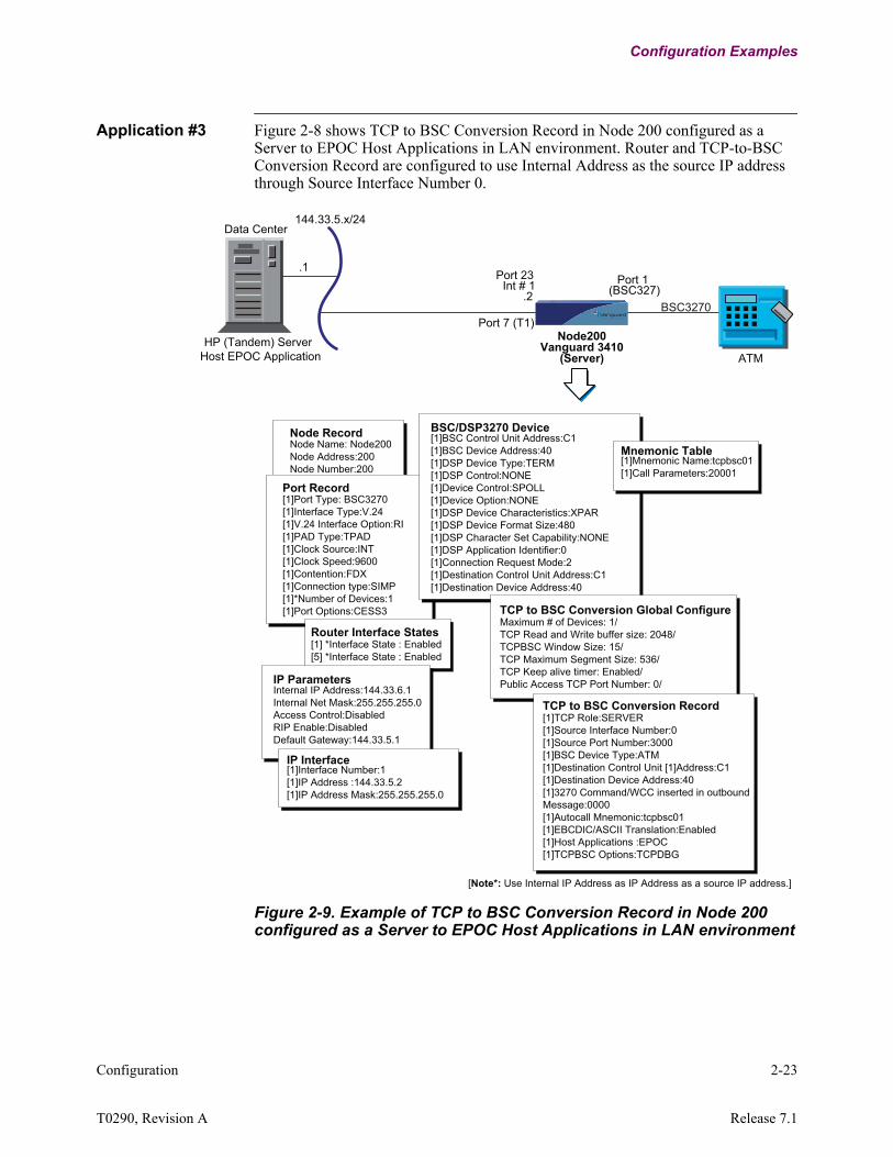
Application #3 Figure 2-8 shows TCP to BSC Conversion Record in Node 200 configured as a Server to EPOC Host Applications in LAN environment. Router and TCP-to-BSC Conversion Record are configured to use Internal Address as the source IP address through Source Interface Number 0.
Figure 2-9. Example of TCP to BSC Conversion Record in Node 200 configured as a Server to EPOC Host Applications in LAN environment
(Server)
Data Center
HP (Tandem) Server
Port 23Int # 1
144.33.5.x/24
Port 1 (BSC327)
ATM
BSC3270
.1
.2
Port 7 (T1)
Host EPOC ApplicationVanguard 3410
Node200
BSC/DSP3270 Device[1]BSC Control Unit Address:C1[1]BSC Device Address:40[1]DSP Device Type:TERM[1]DSP Control:NONE[1]Device Control:SPOLL[1]Device Option:NONE[1]DSP Device Characteristics:XPAR[1]DSP Device Format Size:480[1]DSP Character Set Capability:NONE[1]DSP Application Identifier:0[1]Connection Request Mode:2[1]Destination Control Unit Address:C1[1]Destination Device Address:40
TCP to BSC Conversion Global ConfigureMaximum # of Devices: 1/TCP Read and Write buffer size: 2048/TCPBSC Window Size: 15/TCP Maximum Segment Size: 536/TCP Keep alive timer: Enabled/Public Access TCP Port Number: 0/
Port Record[1]Port Type: BSC3270[1]Interface Type:V.24[1]V.24 Interface Option:RI[1]PAD Type:TPAD[1]Clock Source:INT[1]Clock Speed:9600[1]Contention:FDX[1]Connection type:SIMP[1]*Number of Devices:1[1]Port Options:CESS3
Router Interface States[1] *Interface State : Enabled[5] *Interface State : Enabled
IP Interface[1]Interface Number:1[1]IP Address :144.33.5.2[1]IP Address Mask:255.255.255.0
Mnemonic Table[1]Mnemonic Name:tcpbsc01[1]Call Parameters:20001
[Note*: Use Internal IP Address as IP Address as a source IP address.]
IP ParametersInternal IP Address:144.33.6.1Internal Net Mask:255.255.255.0Access Control:DisabledRIP Enable:DisabledDefault Gateway:144.33.5.1
Node RecordNode Name: Node200Node Address:200Node Number:200
TCP to BSC Conversion Record [1]TCP Role:SERVER[1]Source Interface Number:0[1]Source Port Number:3000[1]BSC Device Type:ATM[1]Destination Control Unit [1]Address:C1[1]Destination Device Address:40[1]3270 Command/WCC inserted in outbound Message:0000[1]Autocall Mnemonic:tcpbsc01[1]EBCDIC/ASCII Translation:Enabled[1]Host Applications :EPOC[1]TCPBSC Options:TCPDBG
2-24 Configuration
Configuration Examples
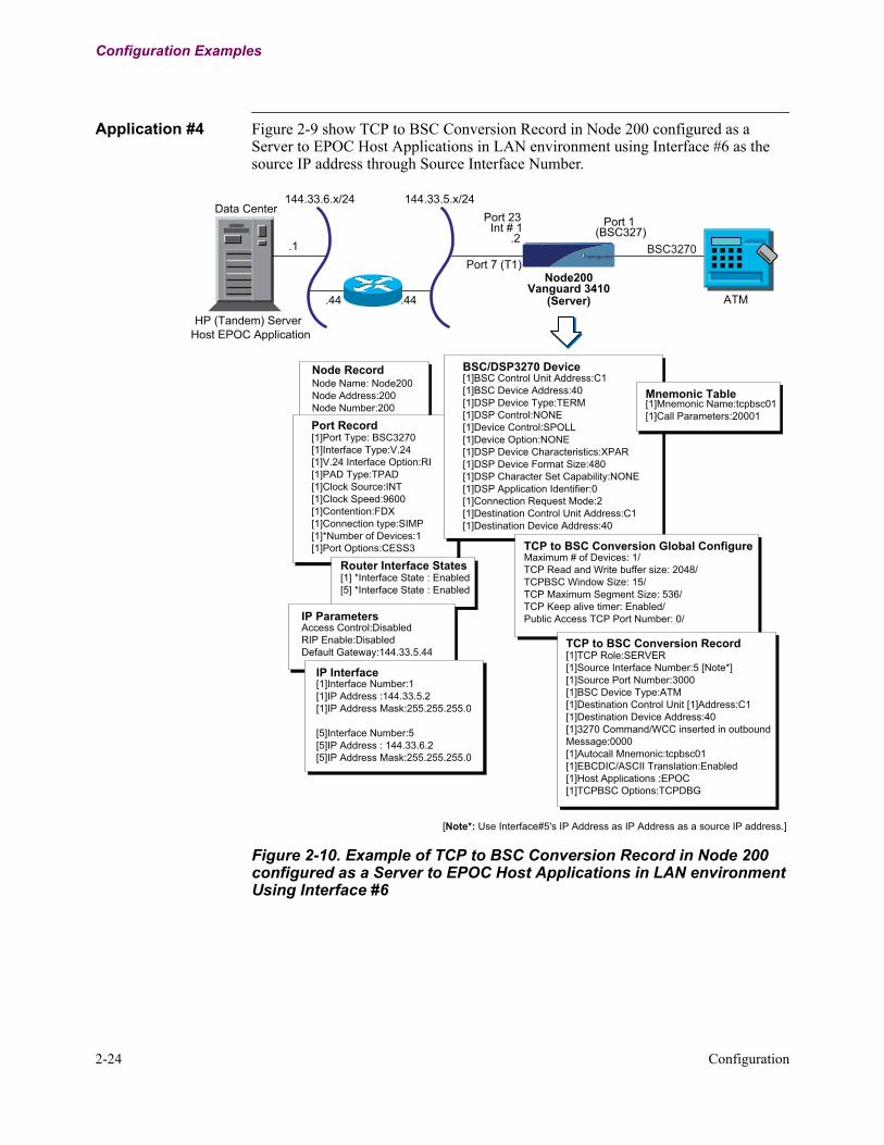
Application #4 Figure 2-9 show TCP to BSC Conversion Record in Node 200 configured as a Server to EPOC Host Applications in LAN environment using Interface #6 as the source IP address through Source Interface Number.
Figure 2-10. Example of TCP to BSC Conversion Record in Node 200 configured as a Server to EPOC Host Applications in LAN environment Using Interface #6
(Server)
Data Center
HP (Tandem) Server
Port 23Int # 1
144.33.6.x/24 144.33.5.x/24
Port 1 (BSC327)
ATM
BSC3270.1
.44 .44
.2
Port 7 (T1)
Host EPOC Application
Vanguard 3410Node200
BSC/DSP3270 Device[1]BSC Control Unit Address:C1[1]BSC Device Address:40[1]DSP Device Type:TERM[1]DSP Control:NONE[1]Device Control:SPOLL[1]Device Option:NONE[1]DSP Device Characteristics:XPAR[1]DSP Device Format Size:480[1]DSP Character Set Capability:NONE[1]DSP Application Identifier:0[1]Connection Request Mode:2[1]Destination Control Unit Address:C1[1]Destination Device Address:40
TCP to BSC Conversion Global ConfigureMaximum # of Devices: 1/TCP Read and Write buffer size: 2048/TCPBSC Window Size: 15/TCP Maximum Segment Size: 536/TCP Keep alive timer: Enabled/Public Access TCP Port Number: 0/
TCP to BSC Conversion Record [1]TCP Role:SERVER[1]Source Interface Number:5 [Note*][1]Source Port Number:3000[1]BSC Device Type:ATM[1]Destination Control Unit [1]Address:C1[1]Destination Device Address:40[1]3270 Command/WCC inserted in outbound Message:0000[1]Autocall Mnemonic:tcpbsc01[1]EBCDIC/ASCII Translation:Enabled[1]Host Applications :EPOC[1]TCPBSC Options:TCPDBG
Port Record[1]Port Type: BSC3270[1]Interface Type:V.24[1]V.24 Interface Option:RI[1]PAD Type:TPAD[1]Clock Source:INT[1]Clock Speed:9600[1]Contention:FDX[1]Connection type:SIMP[1]*Number of Devices:1[1]Port Options:CESS3
Router Interface States[1] *Interface State : Enabled[5] *Interface State : Enabled
IP Interface[1]Interface Number:1[1]IP Address :144.33.5.2[1]IP Address Mask:255.255.255.0
[5]Interface Number:5[5]IP Address : 144.33.6.2[5]IP Address Mask:255.255.255.0
Mnemonic Table[1]Mnemonic Name:tcpbsc01[1]Call Parameters:20001
[Note*: Use Interface#5's IP Address as IP Address as a source IP address.]
IP ParametersAccess Control:DisabledRIP Enable:DisabledDefault Gateway:144.33.5.44
Node RecordNode Name: Node200Node Address:200Node Number:200

Statistics 3-1
T0290, Revision A Release 7.1
Chapter 3Statistics
Introduction This chapter describes how to generate TCP to BSC Statistics.
Types of TCP to BSC Statistics
You can generate these TCP to BSC Statistics:• TCPBSC Device Summary• Detailed TCPBSC Device Statistics by Entry Number• Reset TCPBSC Detailed Statistics by Entry Number
Generate and Reset Statistics
Follow these steps to generate and reset statistics:
TCP to BSC Statistics Menu
Figure 4 below shows the TCP to BSC Statistics Menu.
Figure 4. TCP to BSC Statistics Menu
Step Action Result1 Select Status/statistics
for the Control Terminal Port (CTP) Main Menu.
The menu for Status/statistics displays.
2 Select TCP to BSC Sta-tistics from the Status/statistics Menu
The TCP to BSC Statistics menu dis-plays.
Node: nodename Address: (blank) Date: 12-JAN-01 Time: 7:19:29Menu: SNA Feature Statistics Path:
1. TCPBSC Summary Statistics 2. TCPBSC Detailed Statistics by Entry Number 3. Reset TCPBSC Detailed Statistics by Entry Number

3-2 Statistics
TCPBSC Summary Statistics
Figure 5 below shows selection number 1, the TCP to BSC Summary Statistics.
Figure 5. TCP to BSC Summary Statistics
TCP to BSC Detailed Statistics
Figure 6 shows the Detailed TCPBSC Statistics viewed by entry number:Note
When “TCPBSC-DSP/SES State:” shows Connection Pending, or when attempting a connection, the detailed Call Summary shows a blank time stamp for that device.After TCP session comes up, “TCP Status:” may display one of the following:wfda – waiting for “device active” status from the hostwffb – waiting for first data block from the hostwtrd – waiting to resend “device active” status to the host
Figure 6. Detailed TCPBSC Statistics
IFN Remote CU/ MNEMONICEnt# Role Host Source IP : Port # Type DEV CALL ADR TCP SVC
Destination IP : Port==== ==== ====== =============== ===== === ====== ===== ======== ==== ====1 SRVR BASE24 0.0.0.0 0 6 ATM C1/40 tcpbsc0 DIS down
0.0.0.0 02 CLNT BASE24 144.33.8.2 1025 8 ATM C1/40 tcpbsc02 up up 144.33.4.1 2000
Node: TCPBSC Address: 2706 Date: 13-AUG-2008 Time: 14:47:43Detailed TCPBSC Statistics CLIENT/BASE24 Page: 2 of 2
Entry # 2 TCP Status: up SVC Status: up TCPBSC-TCP State: HDR RD TCPBSC-DSP State: Connected
Dest IP Addr: 144.33.4.1 Dest Port Num: 2000Source IP Addr: 144.33.8.2 Source Port Num: 1025 Source Inf Num: 8 Remote Type: ATM CU/DEV: C1/40
Auto Mnemonic: tcpbsc02 Calling Address Configured: (None)Outb FC: ON Inb FC: OFF Last Outb TCP Seq # Rcv (Hex): 5AF645C7Disconnect or Call Req Fail Reason/Sense Code: --------
IN OUT IN OUTDSP Call Request: 0 2 TCP Data Pkts: 268307 134143
DSP Call Accept: 2 0 TCP Data Bytes: 69357613 68008992DSP Call Reject: 0 0 DSP Turb Data Pkts: 268280 0
DSP Session Disc: 1 0 DSP Data Pkts: 402420 268306DSP Seq# Resyn'd: 0 0 DSP Data Bytes: 69350380 69625407
DSP Circuit Disc: 0 0 DSP Terminal Stat: 2 0DSP Invite to Clr: 0 0 DSP Cmd/Rsp Abt: 0 0
DSP Unknown Disc: 0 0 DSP Cmd/Rsp Fwd Abt: 0 0Max outb blk size from TCP – 512 Max inb blk size from DSP - 512Press any key to continue ( ESC to exit ) ...

Statistics 3-3
T0290, Revision A Release 7.1
Reset TCPBSC Detailed Statistics
Figure 7 shows Reset TCPBSC Detailed Statistics viewed by entry number. In the Detailed Statistics on this page, all IN/OUT numbers have been reset to zero.
Figure 7. Reset TCPBSC Detailed Statistics
Node: TCPBSC Address: 2706 Date: 13-AUG-2008 Time: 14:47:43Detailed TCPBSC Statistics CLIENT/BASE24 Page: 2 of 2
Entry # 2 TCP Status: up SVC Status: up TCPBSC-TCP State: HDR RD TCPBSC-DSP State: Connected
Dest IP Addr: 144.33.4.1 Dest Port Num: 2000Source IP Addr: 144.33.8.2 Source Port Num: 1025 Source Inf Num: 8 Remote Type: ATM CU/DEV: C1/40
Auto Mnemonic: tcpbsc02 Calling Address Configured: (None)Outb FC: ON Inb FC: OFF Last Outb TCP Seq # Rcv (Hex): 5AF645C7Disconnect or Call Req Fail Reason/Sense Code: --------
IN OUT IN OUTDSP Call Request: 0 0 TCP Data Pkts: 268307 0
DSP Call Accept: 0 0 TCP Data Bytes: 69357613 0DSP Call Reject: 0 0 DSP Turb Data Pkts: 268280 0
DSP Session Disc: 0 0 DSP Data Pkts: 402420 0DSP Seq# Resyn'd: 0 0 DSP Data Bytes: 69350380 0
DSP Circuit Disc: 0 0 DSP Terminal Stat: 2 0DSP Invite to Clr: 0 0 DSP Cmd/Rsp Abt: 0 0
DSP Unknown Disc: 0 0 DSP Cmd/Rsp Fwd Abt: 0 0Max outb blk size from TCP – 512 Max inb blk size from DSP - 512Press any key to continue ( ESC to exit ) ...
Reset to Zero

3-4 Statistics

SNA Sense Codes A-1
T00290, Revision A Release 7.1
Error Codes from Networks and Remote Devices
Appendix ASNA Sense Codes
Overview
Introduction This appendix provides descriptions for the SNA Sense Codes.
Error Codes from Networks and Remote Devices
Introduction Error codes received by TCPBSC Conversion from remote devices are displayed through alarms or sense codes in TCPBSC Detailed Statistics. There are four types of codes. Below are the codes (symbols):
• EE - Event Code (X.25)• DD - Diagnostic Code (X.25)• CC - Cause Code (X.25)• SS - Specific Reason Code (BSC3270/BSC2780-to-SNABSC Conversion)

A-2 SNA Sense Codes
Error Codes from Networks and Remote Devices
AlarmsThe alarm displays the error code in the following format when there isdisconnection from the BSC device:Nodename 27-JUN-2002 17:04 LU MMCLU002 DISC FROM DSP DEV(EE, DD, CC, SS)
NoteIf SS’s value is non-zero, then it has greater significance than DD and CC. Otherwise, DD and CC are the more significant code (even if either or both are 00).
Specific Reason Code in TCPBSC Detailed StatisticsThe specific reason code is formatted to indicate any possible reason for disconnect from BSC device.
Byte 0- bits 0-3: always '0000'- bits 4-7: always '1000'Byte 1- bits 0-3: always '1111'- bits 0-1: '00' - from DSP
'01' - future use- bits 2-3: '00' - Bytes 2-3 contain Specific Code
'01' - Event is SASD*; byte 2 contains DSP Diagnostic Codeand byte 3 contains the Cause Code
'10' - Event is SASCBB*; bytes 2 containsDiagnostic Code and bytes 3 contains the Cause Code
'11' - Event is SACD*; bytes 2 and bytes 3 are reservedBytes 2 - 3Specific Code or Diagnostic/Cause Code
Specific Reason Code SummaryThe following tables list the Specific Reason Code received by BSC Device:
SNA Sense Codes A-3
T00290, Revision A Release 7.1
Error Codes from Networks and Remote Devices
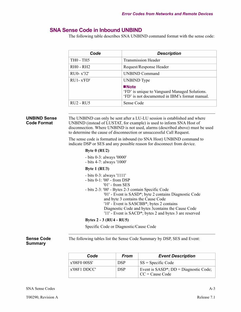
SNA Sense Code in Inbound UNBINDThe following table describes SNA UNBIND command format with the sense code:
UNBIND Sense Code Format
The UNBIND can only be sent after a LU-LU session is established and where UNBIND (instead of LUSTAT, for example) is used to inform SNA Host of disconnection. Where UNBIND is not used, alarms (described above) must be used to determine the cause of disconnection or unsuccessful Call Request.The sense code is formatted in inbound (to SNA Host) UNBIND command to indicate DSP or SES and any possible reason for disconnect from device.
Byte 0 (RU2)- bits 0-3: always '0000'- bits 4-7: always '1000'Byte 1 (RU3)- bits 0-3: always '1111'- bits 0-1: '00' - from DSP
'01' - from SES- bits 2-3: '00' - Bytes 2-3 contain Specific Code
'01' - Event is SASD*; byte 2 contains Diagnostic Code and byte 3 contains the Cause Code'10' - Event is SASCBB*; bytes 2 contains Diagnostic Code and bytes 3contains the Cause Code'11' - Event is SACD*; bytes 2 and bytes 3 are reserved
Bytes 2 - 3 (RU4 - RU5)Specific Code or Diagnostic/Cause Code
Sense Code Summary
The following tables list the Sense Code Summary by DSP, SES and Event:
Code DescriptionTH0 - TH5 Transmission HeaderRH0 - RH2 Request/Response HeaderRU0- x'32' UNBIND CommandRU1- x'FD' UNBIND Type
Note‘FD’ is unique to Vanguard Managed Solutions. ‘FD’ is not documented in IBM’s format manual.
RU2 - RU5 Sense Code
Code From Event Descriptionx'08F0 00SS' DSP SS = Specific Codex'08F1 DDCC' DSP Event is SASD*; DD = Diagnostic Code;
CC = Cause Code

A-4 SNA Sense Codes
Error Codes from Networks and Remote Devices
* Event Codes are described in the next section.
x'08F2 DDCC' DSP Event is SASCBB*; DD = Diagnostic Code; CC = Cause Code
x'08F3 DDCC' DSP Event is SACD*x'08F4 00SS' SES SS = Specific Codex'08F5 DDCC SES Event is SASD*; DD = Diagnostic Code;
CC= Cause Codex'08F6 DDCC' SES Event is SASCBB*; DD = Diagnostic
Code; CC = Cause Code
Code From Event Description

SNA Sense Codes A-5
T00290, Revision A Release 7.1
Error Codes from Networks and Remote Devices
EE - Event Codes
Event Codes The following table lists the Event Codes:
NoteDetails of Diagnostic, Cause, and Specific Reason code are described in this section.
Code DescriptionX'05' - SASD Session DisconnectX'06' - SASCBB SASCBB- Session RejectX'07' - SACD Circuit Disconnect (DSP only)

A-6 SNA Sense Codes
Error Codes from Networks and Remote Devices
DD - Diagnostic Code
Diagnostic Codes The table below lists the Diagnostic Codes that are X.25 or network specific.
Code DescriptionX'00' Generic code; no additional informationX'01' Invalid P(S)X'02' Invalid P(R)X'10' Generic code; packet type invalidX'11' Packet invalid in state R1X'14' Packet invalid in state P1X'15' Packet invalid in state P2X'16' Packet invalid in state P3X'17' Packet invalid in state P4X'18' Packet invalid in state P5X'1B Packet invalid in state D1X'1D' Packet invalid in state D3X'20' Generic code; packet not allowedX'21' Unidentifiable packetX'22' Call on logical one way channelX'23' Invalid packet on PVCX'26' Packet too shortX'27' Packet too longX'29' Invalid bits in packetX'2B' Unauthorized interrupt confX'2C' Unauthorized interruptX'30' Generic code; timer expiredX'31' Timer expired for incoming callX'32' Timer expired for clearX'33' Timer expired for resetX'34' Timer expired for restartX'40' Generic code; call set-up problemX'41' Facilities/region code not allowedX'42' Facilities/region parameter not allowedX'43' Bad called addressX'44' Bad calling addressX'45' Invalid facilities length
SNA Sense Codes A-7
T00290, Revision A Release 7.1
Error Codes from Networks and Remote Devices
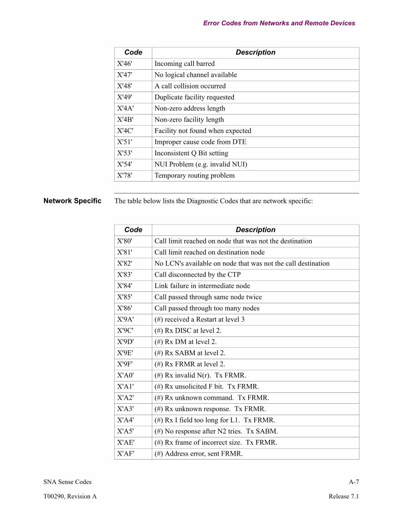
Network Specific The table below lists the Diagnostic Codes that are network specific:
X'46' Incoming call barredX'47' No logical channel availableX'48' A call collision occurredX'49' Duplicate facility requestedX'4A' Non-zero address lengthX'4B' Non-zero facility lengthX'4C' Facility not found when expectedX'51' Improper cause code from DTEX'53' Inconsistent Q Bit settingX'54' NUI Problem (e.g. invalid NUI)X'78' Temporary routing problem
Code Description
Code DescriptionX'80' Call limit reached on node that was not the destinationX'81' Call limit reached on destination nodeX'82' No LCN's available on node that was not the call destinationX'83' Call disconnected by the CTPX'84' Link failure in intermediate nodeX'85' Call passed through same node twiceX'86' Call passed through too many nodesX'9A' (#) received a Restart at level 3X'9C' (#) Rx DISC at level 2.X'9D' (#) Rx DM at level 2.X'9E' (#) Rx SABM at level 2. X'9F' (#) Rx FRMR at level 2.X'A0' (#) Rx invalid N(r). Tx FRMR.X'A1' (#) Rx unsolicited F bit. Tx FRMR.X'A2' (#) Rx unknown command. Tx FRMR.X'A3' (#) Rx unknown response. Tx FRMR.X'A4' (#) Rx I field too long for L1. Tx FRMR.X'A5' (#) No response after N2 tries. Tx SABM.X'AE' (#) Rx frame of incorrect size. Tx FRMR.X'AF' (#) Address error, sent FRMR.

A-8 SNA Sense Codes
Error Codes from Networks and Remote Devices
X'B0' (#) Source port is in BusyOut state.X'B1' (#) Destination port is in BusyOut state.X'B2' (#) DCP reconnection attempt rejected. Do not retryX'B3' /* */X'B4' Cannot bring up a call when configuration is changingX'B5' NS Feature invalid configuration - during table boot.X'B6' (#) Call Request specified unacceptable resourcesX'B8' (#) NUI Database problem (busy, timeout, congestion)X'B9' Invalid Quality Of Service (QoS)X'BA' Clear Request from a Voice end-pointX'BB' Call cleared by port configured for Redirection
Code Description

SNA Sense Codes A-9
T00290, Revision A Release 7.1
Error Codes from Networks and Remote Devices
CC - Cause Codes
Cause Codes The table below lists the Cause Codes that are X.25 or network specific:
For Clear IndicationCode Description
X'01' Number busyX'03' Invalid facility requestX'05' Network congestionX'09' Out of orderX'0B' Access barredX'0D' Not obtainableX'11' Remote procedure errorX'13' Local procedure errorX'15' RPOA out of orderX'19' Reverse charging acceptance not subscribedX'21' Incompatible destinationX'29' Ship absentX'3A' (#) control port intervention
For Reset IndicationCode Description
X'01' Out of order (P)X'03' Remote procedure errorX'05' Local procedure errorX'07' Network congestionX'09' Remote DTE operational (P)X'0F' Network operational (P)X'11' Incompatible destinationX'1D' Network out of order (P) / (P) -- may only be sent on PVCs
A-10 SNA Sense Codes
Error Codes from Networks and Remote Devices
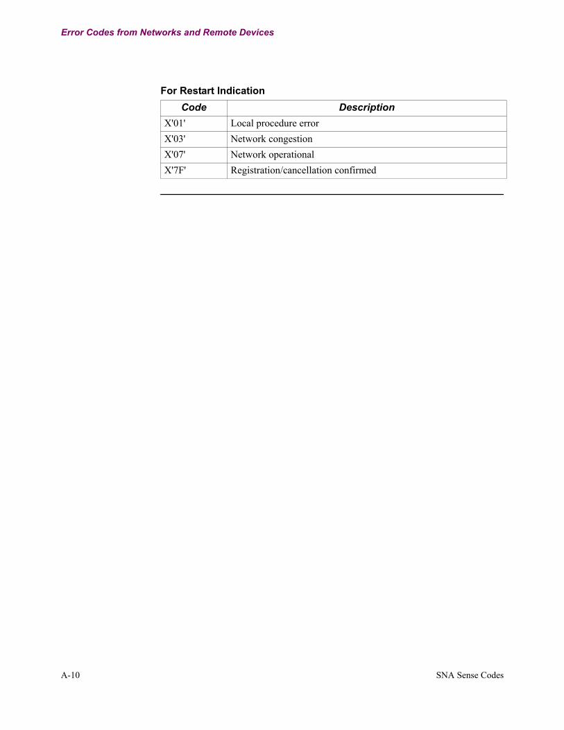
For Restart IndicationCode Description
X'01' Local procedure errorX'03' Network congestionX'07' Network operationalX'7F' Registration/cancellation confirmed
SNA Sense Codes A-11
T00290, Revision A Release 7.1
Error Codes from Networks and Remote Devices
SS - Specific Code
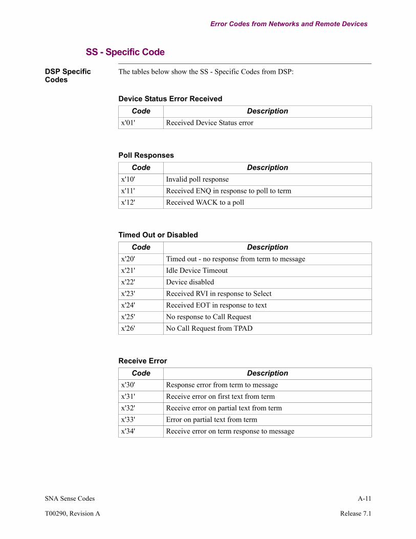
DSP Specific Codes
The tables below show the SS - Specific Codes from DSP:
Device Status Error ReceivedCode Description
x'01' Received Device Status error
Poll ResponsesCode Description
x'10' Invalid poll response x'11' Received ENQ in response to poll to termx'12' Received WACK to a poll
Timed Out or DisabledCode Description
x'20' Timed out - no response from term to messagex'21' Idle Device Timeoutx'22' Device disabledx'23' Received RVI in response to Selectx'24' Received EOT in response to textx'25' No response to Call Requestx'26' No Call Request from TPAD
Receive ErrorCode Description
x'30' Response error from term to messagex'31' Receive error on first text from termx'32' Receive error on partial text from termx'33' Error on partial text from termx'34' Receive error on term response to message
A-12 SNA Sense Codes
Error Codes from Networks and Remote Devices
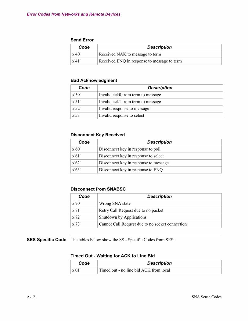
SES Specific Code The tables below show the SS - Specific Codes from SES:
Send ErrorCode Description
x'40' Received NAK to message to termx'41' Received ENQ in response to message to term
Bad AcknowledgmentCode Description
x'50' Invalid ack0 from term to messagex'51' Invalid ack1 from term to messagex'52' Invalid response to messagex'53' Invalid response to select
Disconnect Key ReceivedCode Description
x'60' Disconnect key in response to pollx'61' Disconnect key in response to selectx'62' Disconnect key in response to messagex'63' Disconnect key in response to ENQ
Disconnect from SNABSCCode Description
x'70' Wrong SNA statex'71' Retry Call Request due to no packetx'72' Shutdown by Applicationsx'73' Cannot Call Request due to no socket connection
Timed Out - Waiting for ACK to Line BidCode Description
x'01' Timed out - no line bid ACK from local
SNA Sense Codes A-13
T00290, Revision A Release 7.1
Error Codes from Networks and Remote Devices
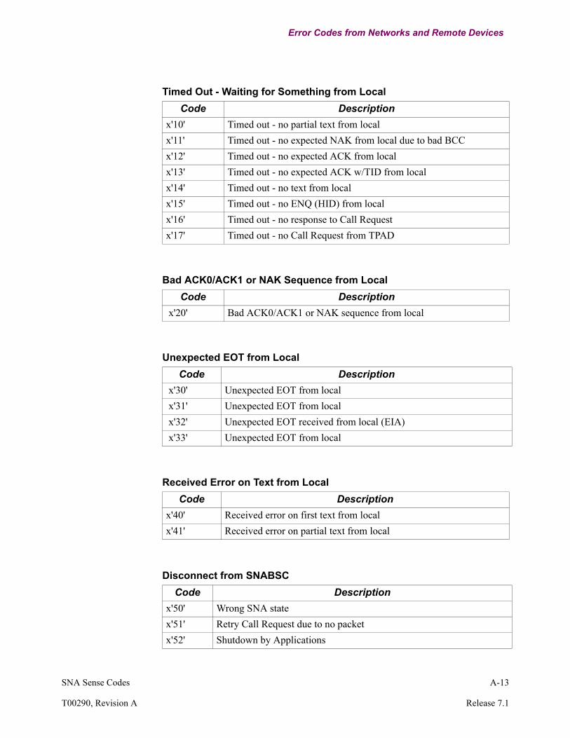
Timed Out - Waiting for Something from LocalCode Description
x'10' Timed out - no partial text from localx'11' Timed out - no expected NAK from local due to bad BCCx'12' Timed out - no expected ACK from localx'13' Timed out - no expected ACK w/TID from localx'14' Timed out - no text from localx'15' Timed out - no ENQ (HID) from localx'16' Timed out - no response to Call Requestx'17' Timed out - no Call Request from TPAD
Bad ACK0/ACK1 or NAK Sequence from LocalCode Description
x'20' Bad ACK0/ACK1 or NAK sequence from local
Unexpected EOT from LocalCode Description
x'30' Unexpected EOT from local x'31' Unexpected EOT from local x'32' Unexpected EOT received from local (EIA) x'33' Unexpected EOT from local
Received Error on Text from LocalCode Description
x'40' Received error on first text from localx'41' Received error on partial text from local
Disconnect from SNABSCCode Description
x'50' Wrong SNA statex'51' Retry Call Request due to no packetx'52' Shutdown by Applications

A-14 SNA Sense Codes
Error Codes from Networks and Remote Devices
x'53' Cannot Call Request due to no socket connection
Disconnect from SNABSCCode Description
2780 PAD is Re-InitializedCode Description
x'60' 2780 PAD is re-initialized
Software ErrorsCode Description
x'C0' Timed out - no expected NAK from local due to time out waiting for remote text
x'C1' Unexpected DISC from remote (EIA)x'C2' Timed out - no text from remotex'C3' Timed out - no flow control clear from remote sidex'C4' Timed out - no text ACK from remotex'C5' Excessive WACK ENQs from local; due to no text ACK from remotex'C6' Timed out - nothing from either directionx'C7' Received Session Bound from remote but local issued a disconnect
requestx'C8' Unexpected event waiting for ACK from remotex'C9' Timed out - no ACK (TID) from remotex'CA' Timed out - no ENQ (HID) from remotex'CB' Bad event - no ENQ (HID) from remote
Unknown ReasonCode Description
x'FF' Unknown reason
Index
Index-1
C
ConfigurationInformation and Examples 2-1, 2-2Overview 2-1
E
Error Codes A-1Examples
Configuration 2-2
H
How the TCP to BSC Conversion Works 1-4
S
SNA Sense Code Descriptions A-1SNA Sense Codes A-1Statistics 3-1
T
TCP to BSC Conversion 1-1Configuration 2-1Configuration Examples 2-20Configuration Information and Examples 2-1Features 1-2How it works 1-4SNA Sense Codes A-1Statistics 3-1Theory of Operation 1-3Typical Applications 1-4
Theory of Operation 1-3Typical Applications 1-4

Index-2