vannes de purge et d'extraction / vanne de … · document non contractuel c - 128 33, av....
TRANSCRIPT
Document non contractuel C - 128
33, av. Franklin Roosevelt - 69150 DÉCINES CHARPIEU - FRANCE - 04 78 58 34 81 - Fax 04 78 69 50 98 - Fax international +33 478 726 965 - [email protected]
VANNES DE PURGE ET D'EXTRACTION / VANNE DE DECONCENTRATION CONTINUE BLOWDOWN VALVE FOR BLEEDING SLUDGE / DECONCENTRATION VALVE
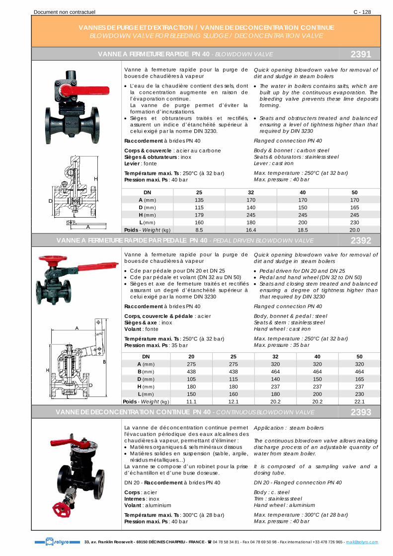
VANNE A FERMETURE RAPIDE PN 40 - BLOWDOWN VALVE 2391
Vanne à fermeture rapide pour la purge de boues de chaudières à vapeur
L’eau de la chaudière contient des sels, dont la concentration augmente en raison de l’évaporation continue. La vanne de purge permet d’éviter la formation d’incrustations.
Sièges et obturateurs traités et rectifiés, assurent un indice d’étanchéité supérieur à celui exigé par la norme DIN 3230.
Raccordement à brides PN 40
Corps & couvercle : acier au carbone Sièges & obturateurs : inox Levier : fonte
Température maxi. Ts : 250°C (à 32 bar) Pression maxi. Ps : 40 bar
Quick opening blowdown valve for removal of dirt and sludge in steam boilers
The water in boilers contains salts, which are built up by the continuous evaporation. The bleeding valve prevents these lime deposits forming.
Seats and obstructers treated and balanced ensuring a level of tightness higher than that required by DIN 3230
Flanged connection PN 40
Body & bonnet : carbon steel Seats & obturators : stainless steel Lever : cast iron
Max. temperature : 250°C (at 32 bar) Max. pressure : 40 bar
DN 25 32 40 50 A (mm) 135 170 170 170 D (mm) 115 140 150 165 H (mm) 179 245 245 245 L (mm) 160 180 200 230
Poids - Weight (kg) 8.5 16.4 18.5 20.0
VANNE A FERMETURE RAPIDE PAR PEDALE PN 40 - PEDAL DRIVEN BLOWDOWN VALVE 2392
Vanne à fermeture rapide pour la purge de boues de chaudières à vapeur
Cde par pédale pour DN 20 et DN 25 Cde par pédale et volant (DN 32 au DN 50) Sièges et axe de fermeture traités et rectifiés
assurant un degré d’étanchéité supérieur à celui exigé par la norme DIN 3230
Raccordement à brides PN 40
Corps, couvercle & pédale : acier Sièges & axe : inox Volant : fonte
Température maxi. Ts : 250°C (à 32 bar) Pression maxi. Ps : 35 bar
Quick opening blowdown valve for removal of dirt and sludge in steam boilers
Pedal driven for DN 20 and DN 25 Pedal and hand wheel (DN 32 to DN 50) Seats and closing stem treated and balanced
ensuring a degree of tightness higher than that required by DIN 3230
Flanged connection PN 40
Body, bonnet & pedal : steel Seats & stem : stainless steel Hand wheel : cast iron
Max. temperature : 250°C (at 32 bar) Max. pressure : 35 bar
DN 20 25 32 40 50 A (mm) 275 275 320 320 320 B (mm) 438 438 464 464 464 D (mm) 105 115 140 150 165 H (mm) 180 180 237 237 237 L (mm) 150 160 180 200 230
Poids - Weight (kg) 11.1 12.1 20.2 20.2 22.1
VANNE DE DECONCENTRATION CONTINUE PN 40 - CONTINUOUS BLOWDOWN VALVE 2393
La vanne de déconcentration continue permet l'évacuation périodique des eaux alcalines des chaudières à vapeur, permettant d'éliminer : Matières organiques & sels minéraux dissous Matières solides en suspension (sable, argile,
résidus métalliques…) La vanne se compose d’un robinet pour la prise d’échantillon et d’une buse doseuse.
DN 20 - Raccordement à brides PN 40
Corps : acier Internes : inox Volant : aluminium
Température maxi. Ts : 300°C (à 28 bar) Pression maxi. Ps : 40 bar
Application : steam boilers The continuous blowdown valve allows realizing discharge process of an adjustable quantity of water from steam boiler. It is composed of a sampling valve and a dosing tube.
DN 20 - Flanged connection PN 40
Body : c. steel Trim : stainless steel Hand wheel : aluminium
Max. temperature : 300°C (at 28 bar) Max. pressure : 40 bar

Document non contractuel C - 129
33, av. Franklin Roosevelt - 69150 DÉCINES CHARPIEU - FRANCE - 04 78 58 34 81 - Fax 04 78 69 50 98 - Fax international +33 478 726 965 - [email protected]
PURGEURS AUTOMATIQUES A FLOTTEUR AUTOMATIC FLOAT VALVES
PURGEURS D'AIR - AIR-VENT VALVES 194 - 194 NI
Pour installations de chauffage Montage en position verticale Etanchéité sur l’axe par joint torique
Raccordement fileté gaz 3/8"
Corps : laiton matricé - réf. 194 Corps : laiton chromé - réf. 194 NI Ressort : inox Flotteur : polypropylène
Température maxi. Ts : 110°C Pression maxi. Ps : 10 bar Pression de fonctionnement : 2.5 bar
For heating installations Operating in vertical position Tightness assured by O-ring
BSP Male threaded connection 3/8"
Body : brass - ref. 194 Body : chromed brass - ref. 194 NI Spring : s. steel Float : polypropylene
Max. temperature : 110°C Max. pressure : 10 bar Working pressure : 2.5 bar
PURGEUR D’AIR GRAND DEBIT & HAUT DE COLONNE - AIR-VENT VALVE 194 HC
Pour installations de chauffage Montage en position verticale Etanchéité sur l’axe par joint torique Sécurité avec bouchon hygroscopique
Raccordement fileté gaz 1/2"
Corps : laiton chromé Ressort : inox Flotteur : polypropylène
Température maxi. Ts : 110°C Pression maxi. Ps : 10 bar Pression de fonctionnement : 4 bar
For heating installations Operating in vertical position Tightness assured by O-ring Safety hygroscopic cap
BSP Male threaded connection 1/2"
Body : chrome plated brass Spring : s. steel Float : polypropylene
Max. temperature : 110°C Max. pressure : 10 bar Working pressure : 4 bar
PURGEUR D’AIR FONTE - C. I. AIR-VENT VALVE 194 MX
Pour débit d’air très élevé dans les installations de chauffage, conditionnement d’air et circuits d’eau chaude
Montage en position verticale
Raccordement taraudé gaz 3/4", 1" ou 1-1/4"
Corps et couvercle : fonte revêtue époxy Flotteur : polypropylène Joint d’étanchéité : caoutchouc NBR
Température maxi. Ts : 115°C Pression maxi. Ps : 12 bar Pression de fonctionnement : 6 bar
For heating installations, air conditioning and distribution of hot water, with very high airflow
Operating in vertical position
BSP Female threaded conn. 3/4", 1" or 1-1/4"
Body and bonnet : epoxy coated C. I. Float : polypropylene Seal : NBR rubber
Max. temperature : 115°C Max. pressure : 12 bar Working pressure : 6 bar
PURGEUR D’AIR INOX - S. STEEL AIR-VENT VALVE 194 AE
Il permet d’éliminer l’air ou un gaz incondensable d’un circuit de liquide.
Convient pour un grand nombre d’applications
Montage en position verticale
Raccordement taraudé gaz F 3/4"
Corps et flotteur : inox 316 Siège : inox AISI 304 Joint de corps : graphite
Température maxi. Ts : 198°C Pression maxi. Ps : 14 bar
Eliminates air or incondensable gas from the line.
Appropriate for great number of applications
Operates in vertical position
BSP Female threaded connection 3/4"
Body and float : AISI 316 Seat : AISI 304 Body gasket : graphite
Max. temperature : 198°C Max. pressure : 14 bar
PURGEUR DE LIQUIDE - LIQUID DRAINER 194 EA
Purgeur d'eau et autres liquides pour circuits d’air comprimé ou de gaz
Débit de purge élevé Installation horizontale (standard) ou
verticale
Raccordement taraudé gaz 1/2", 3/4" ou 1"
Corps et couvercle : fonte GS Flotteur et siège : inox AISI 304
Temp. maxi. Ts : 300°C - P. maxi. Ps : 16 bar ΔP maxi. : 14 bar
Water & other liquid removal in compressed air & gas lines
High flow Operating in horizontal (standard) or
vertical position
BSP Fem. threaded connection 1/2", 3/4" or 1"
Body and bonnet : ductile iron Float and seat : AISI 304
Max. temp. : 300°C - Max. pressure : 16 bar Max. ΔP : 14 bar

Document non contractuel C - 130
33, av. Franklin Roosevelt - 69150 DÉCINES CHARPIEU - FRANCE - 04 78 58 34 81 - Fax 04 78 69 50 98 - Fax international +33 478 726 965 - [email protected]
PURGEURS AUTOMATIQUES A FLOTTEUR AUTOMATIC FLOAT TRAPS
PURGEUR A FLOTTEUR - FLOAT TRAP 2451
Ce purgeur permet d'évacuer des quantités importantes de condensat et s'adapte bien aux variations de débit.
Applications : purge de process [échangeurs, autoclaves, condenseurs en chimie, pharmacie et agro-alimentaire]
Equipé d’une capsule thermostatique pour l’évacuation de l’air au démarrage
Montage en position horizontale
Raccordement taraudé gaz 1/2", 3/4" et 1"
Corps et couvercle : fonte GS Joint : graphite - inox Capsule thermostatique : inox Internes : inox 304
T° maxi. Ts : 250°C - P. maxi. Ps : 16 bar ∆P 4.5, 10 ou 14 bar
Variantes : corps & couvercle en inox 316 Variantes : raccordement à brides PN 40
This trap is specially used where prompt & continuous discharge of condensate is necessary.
Applications : heat exchangers, autoclaves, condensers in chemical, pharmaceutical and food processes
Float trap equipped with a thermostatic capsule for evacuation of the air at start
Installation in horizontal position
BSP Female threaded conn. 1/2", 3/4" and 1"
Body and cover : cast iron Seal : graphite - s. steel Thermostatic capsule : s. steel Trim : AISI 304
Max. temp. : 250°C - Max. pressure : 16 bar ∆P 4.5, 10 or 14 bar
Alternates : body & cover made of AISI 316 Alternates : flanged connection PN 40
DN Raccord. A (mm) B (mm) C (mm) Poids (kg) 15 1/2 150 108 68 3.2 20 3/4 150 108 68 3.2 25 1 167 108 107 4.7
PURGEUR A FLOTTEUR - FLOAT TRAP 2455 B
Applications : pour la purge des installations vapeur moyenne pression
Purgeur équipé d’un filtre pour protéger le mécanisme et d’un regard en verre trempé
Montage en position horizontale (standard) ou verticale (sur demande)
Raccordement à brides PN 16
Corps et couvercle : fonte GS Capsule thermostatique : inox 304 Internes : inox 304
T° maxi. Ts : 250°C - P. maxi. Ps : 16 bar ∆P 4.5, 10, 14 ou 21 bar
Applications : for steam installations with medium pressure
Air-vent trap equipped with a strainer to protect the mechanism, and a sight glass
Installation in horizontal (standard) and vertical (on request) position
Flanged connection PN 16
Body and cover : ductile iron Thermostatic capsule : AISI 304 Trim : AISI 304
Max. temp. : 250°C - Max. pressure : 16 bar ∆P 4.5, 10, 14 or 21 bar
DN A (mm) B (mm) FAF (mm) Poids (kg) 32 290 165 230 20.8 40 290 165 230 21.8 50 305 176 230 33
Réf. 2451 : courbes de débit Réf. 2455 B : courbes de débit
Courbe NOIRE : pression différentielle ∆P = 4.5 bar Courbe BLEUE : pression différentielle ∆P = 10 bar Courbe ROUGE : pression différentielle ∆P = 14 bar

Document non contractuel C - 131
33, av. Franklin Roosevelt - 69150 DÉCINES CHARPIEU - FRANCE - 04 78 58 34 81 - Fax 04 78 69 50 98 - Fax international +33 478 726 965 - [email protected]
ISO 9001 PURGEURS A FLOTTEUR LIBRE FERME FREE FLOAT STEAM TRAPS
PURGEUR DE VAPEUR INOX - S. STEEL STEAM TRAP 2420
Purgeur pour conduites de vapeur et lignes de traçage ; sans aucun entretien. Le flotteur fermé libre auto-modulant assure une évacuation continue à faible vitesse, quel que soit le débit du condensat. La purge d’air automatique, bimétallique, permet une mise en route rapide.
Crépine incorporée de grande surface Montage position horizontale ou verticale
Raccordement taraudé gaz, SW ou à brides
Corps & flotteur : inox 316 L Crépine : inox 304 Bilame purge d’air : bimétal
Température maxi. Ts : 400°C Ps et ∆P maxi. : 5, 10 ou 21 bar
Trap for steam mains and tracer lines ; maintenance free. Self-modulating free float provides continuous, smooth, low velocity condensate discharge as process loads vary. Automatic bimetal air vent for rapid start.
Built-in screen with large area holds back impurities
Installation : horizontal or vertical
BSP Fem. threaded, SW or flanged connect.
Body & float : AISI 316 L Screen : AISI 304 Air vent strip : bimetal
Max. temperature : 400°C Max. pressure & max. ∆P : 5, 10 or 21 bar
DN H (mm) h (mm) L (mm) Poids (kg) 1/2 76 52 127 0.8 3/4 76 52 154 1.0 1 76 52 165 1.2
PURGEUR DE VAPEUR FONTE GS - D. I. STEAM TRAP 2423
Purgeur pour tous types d’équipements de chauffage. La capsule thermostatique avec position ouverte en cas de défaillance purge l’air automatiquement, jusqu’à ce que la température soit proche de celle de la vapeur.
Flotteur fermé libre auto-modulant Crépine incorporée de grande surface
Raccordement taraudé gaz ou à brides
Corps & couvercle : fonte GS Flotteur : inox 316 L Crépine interne/externe : inox Capsule thermostatique : inox
Température maxi. Ts : 200°C Ps et ∆P maxi. : 2, 5, 8, 10, 13 bar
Steam trap used on process equipment. Thermostatic capsule with "fail open" feature vents air automatically until close-to-steam temperature. Only one moving part, the free float, eliminates concentrated valve wear & provides long maintenance-free service life
Self-modulating free float Built-in screen with large area holds
BSP Fem. threaded or flanged connection
Body & cover : ductile iron Float : AISI 316 L Outside/inside screen : s. steel Thermostatic capsule : s. steel
Max. temperature : 200°C Max. pressure & max. ∆P : 2, 5, 8, 10, 13 bar
DN H (mm) h (mm) L (mm) W (mm) Poids (kg) 1/2 130 75 120 80 2.7 3/4 130 73 120 80 2.8 1 137 75 120 80 3.0
Réf. 2420 : courbes de débit Réf. 2423 : courbes de débit
Les numéros des courbes représentent les numéros d’orifice. La pression différentielle est la différence entre les pressions à l’Entrée et à
la Sortie du purgeur. Les débits sont donnés pour une évacuation continue du condensat à 6°C
en-dessous de la température de la vapeur saturée. Facteur de sécurité recommandé : au moins 1.5.
Line numbers refer to orifice numbers. Differential pressure is the difference between the Inlet and Outlet
pressure of the trap. Capacities are based on continuous discharge of condensate 6°C
below steam temperature. Recommended safety factor : at least 1.5.
Document non contractuel C - 132
33, av. Franklin Roosevelt - 69150 DÉCINES CHARPIEU - FRANCE - 04 78 58 34 81 - Fax 04 78 69 50 98 - Fax international +33 478 726 965 - [email protected]
PURGEURS THERMOSTATIQUES THERMOSTATIC STEAM TRAPS
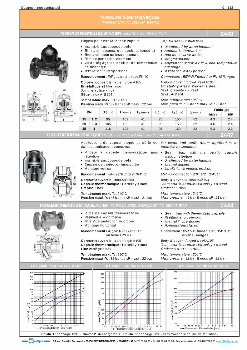
PURGEUR BIMETALLIQUE ACIER - BIMETALLIC STEAM TRAP 2449
Purgeur pour installations de vapeur
Insensible aux coups de bélier Elimination automatique des bouchons d’air Effet anti-retour sur les condensats Filtre de protection incorporé Vis de réglage de débit et de température
de décharge Installation toutes positions
Raccordement : FxF gaz ou à brides PN 40
Corps et couvercle : acier forgé A105 Bimétallique et filtre : inox Joint : graphite - inox Siège : inox AISI 304
Température maxi. Ts : 250°C Pression maxi. Ps : 32 bar et ∆P maxi. : 22 bar
Trap for steam installations
Unaffected by water hammer Automatic deaeration Non-return valve action Integral strainer Adjustment screw air flow and temperature
discharge Installation in any position
Connection : BSPP FxF thread or PN 40 flanges
Body & cover : forged steel A105 Bimetallic plates & strainer : s. steel Seal : graphite - s. steel Seat : AISI 304
Max. temperature : 250°C Max. pressure : 32 bar & max. ∆P : 22 bar
DN D (mm) H (mm) H2 (mm) L (mm) L1 (mm) L2 (mm) Poids (kg) Brides BSP
15 1/2 95 102 41 95 150 82 4.3 2.4 20 3/4 105 102 41 95 150 82 4.6 2.4 25 1 115 102 41 95 150 82 5.3 2.3
PURGEUR THERMOSTATIQUE INOX - S. STEEL THERMOSTATIC STEAM TRAP 2447
Applications de vapeur propre et stérile ou dans les ambiances corrosives
Purgeur à capsule thermostatique sans rétention
Insensible aux coups de bélier Crépine de protection incorporée Montage vertical
Raccordement : FxF gaz 3/8", 1/2", 3/4", 1"
Corps et couvercle : inox AISI 304 Capsule thermostatique : Hastelloy + inox Crépine : inox
Température maxi. Ts : 240°C Pression maxi. Ps : 45 bar et ∆P maxi. : 21 bar
For clean and sterile steam applications or corrosive environments
Steam trap with thermostatic capsule without retention
Unaffected by water hammer Integral strainer Installation in vertical position
BSP FxF connection 3/8", 1/2", 3/4", 1"
Body & cover : s. steel AISI 304 Thermostatic capsule : Hastelloy + s. steel Strainer : s. steel
Max. temperature : 240°C Max. pressure : 45 bar & max. ∆P : 21 bar
PURGEUR THERMOSTATIQUE ACIER - FORGED STEEL THERMOSTATIC STEAM TRAP 2444
Purgeur à capsule thermostatique Résistant à la corrosion Filtre Y de protection incorporé Montage horizontal
Raccordement FxF gaz 1/2", 3/4" et 1" Raccordement ou brides PN 40
Corps et couvercle : acier forgé A105 Capsule thermostatique : Hastelloy + inox Filtre et siège : inox
Température maxi. Ts : 250°C Pression maxi. Ps : 32 bar et ∆P maxi. : 22 bar
Steam trap with thermostatic capsule Resistance to corrosion Integral Y type strainer Horizontal Installation
Connection : BSPP FxF thread 1/2", 3/4" & 1" or PN 40 flanges
Body & cover : forged steel A105 Thermostatic capsule : Hastelloy + s. steel Strainer & seat : + s. steel
Max. temperature : 250°C Max. pressure : 32 bar & max. ∆P : 22 bar
Réf. 2449 : courbes de débit Réf. 2447 : courbes de débit Réf. 2444 : courbes de débit
Courbe 1 : décharge 10°C - Courbe 2 : décharge 20°C - Courbe 3 : décharge 30°C (en dessous de la courbe de saturation)

Document non contractuel C - 133
33, av. Franklin Roosevelt - 69150 DÉCINES CHARPIEU - FRANCE - 04 78 58 34 81 - Fax 04 78 69 50 98 - Fax international +33 478 726 965 - [email protected]
PURGEURS THERMODYNAMIQUES THERMODYNAMIC STEAM TRAPS
PURGEUR ACIER - FORGED STEEL STEAM TRAP 2470
Pour la purge des tuyauteries de distribution et installations de traçage vapeur Insensible aux coups de bélier, aux
surchauffes éventuelles et au gel Contrepression aval jusqu'à 80 % de la
pression amont Construction compacte et robuste Filtre Y incorporé Installation toute position
Raccordement : FxF gaz ou à brides PN 40
Corps : acier forgé A105 Chapeau et siège : inox AISI 304 Filtre : inox Disque : inox AISI 420
T° maxi. Ts : 400°C - Pression maxi. Ps : 40 bar ∆P maxi. : 32 bar
Options : raccordement NPT ou SW
For draining distribution pipes and steam tracing installation Unaffected by water hammer, overheating
and frost Maximum opposite pressure should never
exceed 80 % of front pressure Compact and robust Integral Y type strainer Installation in any position
Connection : BSPP FxF or PN 40 Flanges
Body : forged steel A105 Cover and seat : AISI 304 Strainer : s. steel Disc : AISI 420
Max. T° : 400°C - Max. pressure : 40 bar Max. ∆P : 32 bar
Options : NPT or SW connection
DN D (mm)
H1 (mm)
H2 (mm)
L (mm)
L1 (mm)
Poids (kg) Brides BSP
15 1/2 95 100 42 150 95 3.4 1.8 20 3/4 105 100 42 150 95 4.1 1.7 25 1 115 100 42 160 95 4.5 1.6
PURGEUR INOX - S. STEEL STEAM TRAP 2471
Insensible aux coups de bélier, aux surchauffes éventuelles et au gel
Contrepression aval jusqu'à 80 % de la pression amont
Filtre Y incorporé Installation toute position
Raccordement taraudé gaz 1/2", 3/4" et 1"
Corps : inox Chapeau et filtre : inox AISI 304 Disque : inox AISI 420
T° maxi. Ts : 400°C - Pression maxi. Ps : 42 bar
Options : raccordement NPT ou SW
Unaffected by water hammer, overheating and frost
Maximum back pressure should never exceed 80 % of inlet pressure
Integral Y type strainer Installation in any position
BSP Fem. threaded conn. 1/2", 3/4" and 1"
Body : s. steel Cover and strainer : AISI 304 Disc : AISI 420
Max. T° : 400°C - Max. pressure : 42 bar
Options : NPT or SW connection
DN A (mm)
H (mm)
H1 (mm)
H2 (mm)
L (mm)
Poids (kg)
32 41 41 95 33 78 0.94 40 41 43 110 39 90 1.10 50 55 52 124 45 95 1.60
Réf. 2470 : courbe de débit Réf. 2471 : courbes de débit
Document non contractuel C - 134
33, av. Franklin Roosevelt - 69150 DÉCINES CHARPIEU - FRANCE - 04 78 58 34 81 - Fax 04 78 69 50 98 - Fax international +33 478 726 965 - [email protected]
ISO 9001 PURGEURS THERMOSTATIQUES THERMOSTATIC STEAM TRAPS
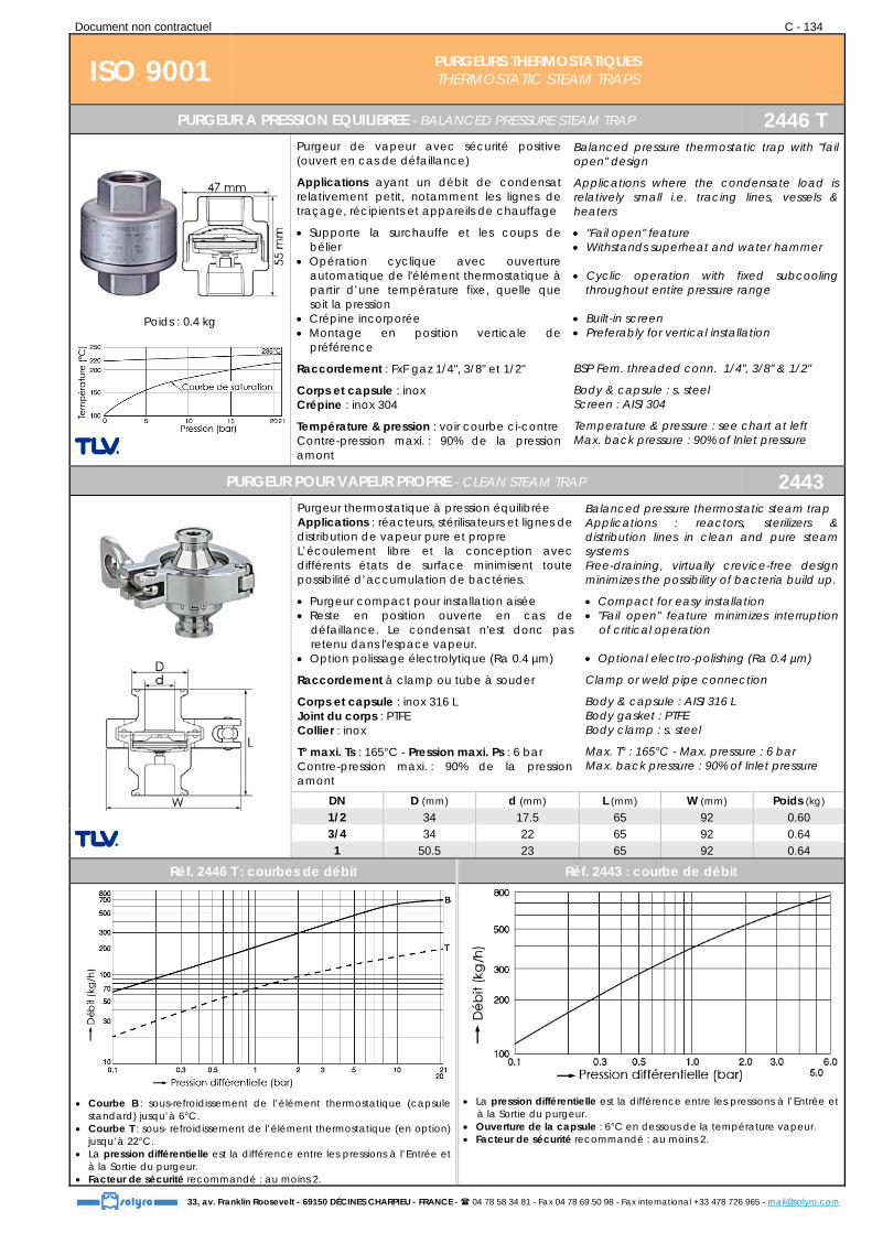
PURGEUR A PRESSION EQUILIBREE - BALANCED PRESSURE STEAM TRAP 2446 T
Poids : 0.4 kg
Purgeur de vapeur avec sécurité positive (ouvert en cas de défaillance)
Applications ayant un débit de condensat relativement petit, notamment les lignes de traçage, récipients et appareils de chauffage
Supporte la surchauffe et les coups de bélier
Opération cyclique avec ouverture automatique de l'élément thermostatique à partir d’une température fixe, quelle que soit la pression
Crépine incorporée Montage en position verticale de
préférence
Raccordement : FxF gaz 1/4", 3/8" et 1/2"
Corps et capsule : inox Crépine : inox 304
Température & pression : voir courbe ci-contre Contre-pression maxi. : 90% de la pression amont
Balanced pressure thermostatic trap with "fail open" design
Applications where the condensate load is relatively small i.e. tracing lines, vessels & heaters
"Fail open" feature Withstands superheat and water hammer Cyclic operation with fixed subcooling
throughout entire pressure range Built-in screen Preferably for vertical installation
BSP Fem. threaded conn. 1/4", 3/8" & 1/2"
Body & capsule : s. steel Screen : AISI 304
Temperature & pressure : see chart at left Max. back pressure : 90% of Inlet pressure
PURGEUR POUR VAPEUR PROPRE - CLEAN STEAM TRAP 2443
Purgeur thermostatique à pression équilibrée Applications : réacteurs, stérilisateurs et lignes de distribution de vapeur pure et propre L’écoulement libre et la conception avec différents états de surface minimisent toute possibilité d’accumulation de bactéries.
Purgeur compact pour installation aisée Reste en position ouverte en cas de
défaillance. Le condensat n'est donc pas retenu dans l'espace vapeur.
Option polissage électrolytique (Ra 0.4 µm)
Raccordement à clamp ou tube à souder
Corps et capsule : inox 316 L Joint du corps : PTFE Collier : inox
T° maxi. Ts : 165°C - Pression maxi. Ps : 6 bar Contre-pression maxi. : 90% de la pression amont
Balanced pressure thermostatic steam trap Applications : reactors, sterilizers & distribution lines in clean and pure steam systems Free-draining, virtually crevice-free design minimizes the possibility of bacteria build up.
Compact for easy installation "Fail open" feature minimizes interruption
of critical operation Optional electro-polishing (Ra 0.4 µm)
Clamp or weld pipe connection
Body & capsule : AISI 316 L Body gasket : PTFE Body clamp : s. steel
Max. T° : 165°C - Max. pressure : 6 bar Max. back pressure : 90% of Inlet pressure
DN D (mm) d (mm) L (mm) W (mm) Poids (kg) 1/2 34 17.5 65 92 0.60 3/4 34 22 65 92 0.64 1 50.5 23 65 92 0.64
Réf. 2446 T : courbes de débit Réf. 2443 : courbe de débit
Courbe B : sous-refroidissement de l’élément thermostatique (capsule standard) jusqu’à 6°C.
Courbe T : sous- refroidissement de l’élément thermostatique (en option) jusqu’à 22°C.
La pression différentielle est la différence entre les pressions à l’Entrée et à la Sortie du purgeur.
Facteur de sécurité recommandé : au moins 2.
La pression différentielle est la différence entre les pressions à l’Entrée et à la Sortie du purgeur.
Ouverture de la capsule : 6°C en dessous de la température vapeur. Facteur de sécurité recommandé : au moins 2.
Document non contractuel C - 135
33, av. Franklin Roosevelt - 69150 DÉCINES CHARPIEU - FRANCE - 04 78 58 34 81 - Fax 04 78 69 50 98 - Fax international +33 478 726 965 - [email protected]
POSTE DE PURGE / COLLECTEUR AVEC PURGEUR TRAP STATION / MANIFOLD WITH STEAM TRAP
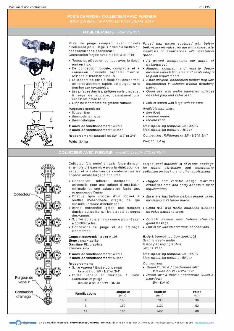
POSTE DE PURGE - TRAP STATION
Poste de purge compact avec robinets d'isolement pour usage sur des clarinettes ou des conduites de condensat ; Construction forgée avec robinet à soufflet.
Toutes les pièces en contact avec le fluide sont en inox.
De conception robuste, compacte et à connexion universelle, l'appareil minimise l'espace d'installation requis.
Le raccord de bride à deux boulons permet un remplacement rapide du purgeur sans toucher aux tuyauteries.
Les surfaces durcies, stellitées sur le clapet et le siège de soupape, garantissent une excellente étanchéité.
Crépine incorporée de grande surface
Purgeurs disponibles : flotteur libre thermodynamique thermostatique
T° maxi. de fonctionnement : 400°C P. maxi. de fonctionnement : 46 bar
Raccordement : taraudé ou SW - 1/2" et 3/4"
Poids : 3.4 kg
Forged trap station equipped with built-in bellows sealed valve ; for use with condensate manifolds or applications with installation space.
All wetted components are made of stainless steel.
Rugged, compact and versatile design minimizes installation area and easily adapts to plant requirements.
2-bolt universal connection permits trap unit replacement in minutes without disturbing piping.
Good seal with stellite hardened surfaces on valve plug and valve seat.
Built-in screen with large surface area
Available trap units : free float thermodynamic thermostatic
Max. operating temperature : 400°C Max. operating pressure : 46 bar
Connection : FxF thread or SW - 1/2" & 3/4"
Weight : 3.4 kg
COLLECTEUR AVEC PURGEUR - MANIFOLD WITH STEAM TRAP
Collecteur [clarinette] en acier forgé dans un ensemble pré-assemblé pour la distribution de vapeur et la collection de condensat sur les applications de traçage et autres
Conception robuste, compacte et universelle pour une surface d’installation minimale et une adaptation facile aux exigences de l’usine
Chaque ligne dispose d’un robinet à soufflet d’étanchéité intégré, ce qui minimise l’espace d’installation.
Bonne étanchéité grâce aux surfaces durcies au stellite sur les clapets et sièges des vannes
Soufflet durable en inox conçu pour résister à 10 000 cycles
Connexions de purge et de drainage incorporées
Corps et couvercle : acier A 105 Siège : inox + stellite Garniture PE : graphite Internes : inox
T° maxi. de fonctionnement : 400°C P. maxi. de fonctionnement : 50 bar
Raccordements Sortie vapeur / Entrée condensat taraudé ou SW - 1/2" et 3/4" Entrée vapeur et drainage / Sortie
condensat et purge douille à souder SW - DN 40
Forged steel manifold in all-in-one package for steam distribution and condensate collection on tracing and other applications
Rugged and versatile design minimizes installation area and easily adapts to plant requirements.
Each line has built-in bellows sealed valve,
minimizing installation space. Good seal with stellite hardened surfaces
on valve discs and seats Durable stainless steel bellows eliminate
gland leakage. Built-in blowdown and drain connections
Body & bonnet : carbon steel A105 Seat : s. steel + stellite Gland packing : graphite Trim : s. steel
Max. operating temperature : 400°C Max. operating pressure : 50 bar
Connections Steam Outlet & / condensate Inlet screwed or SW - 1/2" & 3/4" Steam Inlet & drain / condensate Outlet &
blowdown SW - DN 40
Ramifications Longueur (mm)
Hauteur (mm)
Poids (kg)
4 160 790 36
8 160 1120 52
12 160 1450 69 21

Document non contractuel C - 136
33, av. Franklin Roosevelt - 69150 DÉCINES CHARPIEU - FRANCE - 04 78 58 34 81 - Fax 04 78 69 50 98 - Fax international +33 478 726 965 - [email protected]
VANNES DE REGULATION PNEUMATIQUES - VANNES THERMOSTATIQUES - REGULATEURS DE PRESSION PNEUMATIC CONTROL VALVES - THERMOSTATIC VALVES - PRESSURE REGULATORS
VANNES DE REGULATION PNEUMATIQUES - PNEUMATIC CONTROL VALVES Vanne de régulation à membrane
DN 15 au DN 100
Diaphragm control valve
DN 15 to DN 100
Vanne de régulation à passage droit DN 15 au DN 250
Globe control valve
DN 15 to DN 250
Vanne de réglage à soufflet revêtement PFA DN 15 au DN 100
RICHTER bellows-sealed globe control valve - PFA lining
DN 15 to DN 100
Corps : fonte aciérée / sphéroïdale / inox Membrane : Butyl B en standard Pression nominale : PN 10 Exécution brides selon DIN, BS ou ANSI
Body : cast iron / spheroidal C.I / s. steel Diaphragm : Butyl B Nominal pressure : PN 10 Flange execution : acc. to DIN, BS or ANSI
Corps : fonte / acier / inox Clapet de vanne : à portée d'étanchéité métallique, ou souple Pression nominale : PN 10 à 40 Exécution brides : selon DIN
Body : cast iron / c. steel / s. steel Valve plug : metal or soft sealing Nominal pressure : PN 10 to 40 Flange execution : acc. to DIN
Corps - fonte GS revêtue PFA Siège - PTFE renforcé et modifié Soufflet en PTFE Brides PN 16 ; ANSI classe 150
Ductile iron body with PFA lining Seat - Strengthened and modified PTFE PTFE bellows Flanges PN 16 ; ANSI class 150
VANNES THERMOSTATIQUES - THERMOSTATIC VALVES Régulateurs de température automoteurs
DN 15 au DN 250 - PN 16 à 40 ; ANSI classe 150 à 300 Self-operated temperature regulators
DN 15 to DN 250 - PN 16 to 40 ; ANSI class 150 to 300
Equipage thermostatique Thermostatic actuator
L’équipage thermostatique est l’organe de mesure et de commande de la soupape. Il se compose d’une sonde de température, d’un réglage de consigne, d’un capillaire de liaison et d’un piston de travail et de commande. The thermostatic actuator is measuring the temperature in the pipe and actuates the valve. It consists of temperature sensor, set point adjuster, capillary tube and working piston.
Pour liquides et vapeur ; montage sur canalisations, réservoirs et autres installations de chauffage ou de refroidissement. Consignes : -10 à +250°C Températures : jusqu'à 150°C
For liquid and steam ; suitable for installations in pipelines, tanks and other heating or cooling installations. Set point range : -10 to +250°C Temperature : up to 150°C
Pour liquides, air, et autres gaz ; montage sur gaines d'air, réservoirs, canalisations et installations de chauffage ou de refroidissement ; pour régulation de liquides avec courts délais de réponse. Consignes : -10 à +250°C - T° : jusqu'à 350°C
For liquids, air and other gases ; suitable for installations in air ducts, tanks, pipelines and other heating or cooling installations ; also for liquid control systems with short response times. Set point range : -10 to +250°C - T° : up to 350°C
REGULATEURS DE PRESSION - PRESSURE REGULATORS
Détendeur pour utilisation sur fluide thermique (eau, huile, acides et gaz) du DN 20 au DN 100 Tarage : de 0.06 à 14.29 bar Corps : fonte / acier / inox Brides PN 16 - PN 40 Reducing valve for use with thermal fluid (water, oil, acids and gases) From DN 20 to DN 100 Set pressure : from 0.06 to 14.29 bar Body : cast iron / c. steel / s. steel Flanged connection PN 16 - PN 40
Détendeur pour utilisation sur vapeur du DN 20 au DN 100 Tarage : de 0.06 à 14.6 bar Corps : fonte / acier / inox Brides PN 16 - PN 40 Reducing valve for steam use From DN 20 to DN 100 Set pressure : from 0.06 to 14.6 bar Body : cast iron / c. steel / s. steel Flanged connection PN 16 - PN 40

Document non contractuel C - 137
33, av. Franklin Roosevelt - 69150 DÉCINES CHARPIEU - FRANCE - 04 78 58 34 81 - Fax 04 78 69 50 98 - Fax international +33 478 726 965 - [email protected]
TRAITEMENT DE L'AIR AIR LINE EQUIPMENT
ENSEMBLE FILTRE + REGULATEUR + LUBRIFICATEUR - UNIT FILTER + REGULATOR + LUBRICATOR 2790 FRL
Raccordement gaz G1/4 - G3/8 - G1/2
G3/4 & G1
Ensemble pré-monté, prêt à installer comprenant : filtre-régulateur et lubrificateur "micro-fog" (micro-brouillard)
Haute efficacité de filtration des particules et de l’eau (élément filtrant 40 µm)
Bouton de réglage verrouillable et cadenassable avec manchon de sécurité
Visibilité totale (360°) du réglage de lubrification
Matériaux : cf. éléments constituants (réf. 2790 F, 2790 R et 2790 L)
Pression d’Entrée maxi. : cf. éléments constituants Plage de pression de Sortie : cf. réf. 2790 R
Options : manomètre, vanne d’arrêt, équerre de fixation, autres pressions de Sortie
Boxed set, ready to install, including : filter regulator and micro-fog lubricator
High efficiency water and particle removal (filtering element 40 µm)
Push to lock adjusting knob with tamper resistant option
All round (360°) visibility of lubricator sight feed dome
Materials : see components (ref. 2790 F, 2790 R and 2790 L)
Max. Inlet pressure : see components Outlet pressure range : see ref. 2790 R
Options : pressure gauge, exhausting shut-off valve, mounting bracket, alternative Outlet pressure range
FILTRE + REGULATEUR - FILTER + REGULATOR 2790 FR
Haute efficacité de filtration des particules et de l’eau (élément filtrant de 40 µm)
Cuve à démontage rapide par système 1/4 de tour avec sécurité
Bouton de réglage verrouillable Caractéristiques identiques à l’ensemble 2790 FRL, mais sans lubrificateur Options : cf. 2790 F et 2790 R
High efficiency water and particle removal (filtering element 40 µm)
Quick release bayonet bowl Push to lock adjusting knob with tamper resistant
accessory Same features as ref. 2790 FRL, but without lubricator Options : see 2790 F & 2790 R
FILTRE - FILTER 2790 F
Elimination efficace des particules liquides et solides (élément filtrant de 40 µm)
Corps : Zamak ou alu. selon DN Cuve : - polycarbonate transparent (-20°C +50°C) du 1/4" au 1/2" Cuve : - aluminium (-20°C +80°C) en 3/4" et 1"
Pression d’Entrée maxi. : 10 bar (1/4" au 1/2") 17 bar (3/4" et 1")
Options : indicateur de colmatage filtration 5 µm, 25 µm
Effective liquid removal and positive solid filtration (filtering element 40 µm)
Body : Zinc or aluminium acc. to DN Bowl : - transparent Polycarbonate (-20°C + 50°C) from 1/4" to 1/2"
- aluminium (-20°C + 80°C) for 3/4" & 1"
Max. Inlet pressure : 10 bar (1/4" to 1/2") Max. Inlet pressure : 17 bar (3/4" & 1")
Options : service life indicator 5 µm, 25 µm filter elements
REGULATEUR - REGULATOR 2790 R
Clapet équilibré pour assurer d’excellentes caractéristiques de régulation
Equipé de soupape de décharge
Corps : Zamak ou alu. selon DN
Température ambiante : -20°C à 65°C
Pression d’Entrée maxi. : 20 bar (17 bar en 3/4") Réglage de Sortie : 0.3…10 bar (0.4 à 8 bar en 1")
Orifice pour manomètre : G 1/8
Options : manomètre sans soupape de décharge réglage de Sortie 0.3…2 bar ou 0.3…4 bar
Balanced valve design for optimum pressure control
Equipped with relief valve
Body : Zinc or aluminium acc. to DN
Ambient temperature : -20°C to 65°C
Max. Inlet pressure : 20 bar (17 bar for 3/4") Outlet pressure : 0.3…10 bar (0.4 to 8 bar for 1")
Gauge port : 1/8" BSP
Options : pressure gauge without relieving diaphragm Outlet pressure : 0.3…2 bar or 0.3…4 bar
LUBRIFICATEUR - LUBRICATOR 2790 L
Lubrificateur "micro-fog" (micro-brouillard) pour applications générales et circuits complexes
Cuve à démontage rapide par système 1/4 de tour avec sécurité : transparente en polycarbonate (1/4" au 1/2") métallique en Zamak (3/4" et 1")
Pression maxi. : 10 bar (1/4" au 1/2") 17 bar (3/4" et 1")
Micro-fog plug-in lubricator for most general purpose pneumatic applications
Quick release bayonet bowl : transparent polycarbonate (1/4" to 1/2") metal bowl (zinc alloy) (3/4" & 1")
Max. pressure : 10 bar (transparent bowl) 17 bar (metal bowl)

Document non contractuel C - 138
33, av. Franklin Roosevelt - 69150 DÉCINES CHARPIEU - FRANCE - 04 78 58 34 81 - Fax 04 78 69 50 98 - Fax international +33 478 726 965 - [email protected]
REDUCTEURS DE PRESSION PRESSURE REDUCING VALVES
REDUCTEUR DE PRESSION F/F - P. R. V. F/F 2800
Réducteur de pression à membrane Utilisation sur eau, gaz neutre et fioul domestique
Fonctionnement toutes positions (en respectant le sens d’écoulement)
Sans aucun entretien, sans risque de blocage car insensible au tartre et aux impuretés d’eau
Equipé de 2 prises latérales 1/4" pour manomètre aval et purge
Plage de réglage aval : 1 à 7 bar (livré non réglé)
Raccordement taraudé gaz
Corps : bronze Chapeau : laiton ou bronze Membrane : NBR (Nitrile armé polyamide) Ressort : acier traité anticorrosion
Température de service : -10 +80°C (Ts : 40°C pour fioul domestique) Pression maxi. Ps : 25 bar (liquides du groupe 2)
Diaphragm type pressure reducing valve For water, inert gases and domestic fuel oil
Can be installed in any position No maintenance required, not affected by
scale or dirt Equipped with 2 pressure gauge connections
1/4" and drain at the bottom of the casing Setting from 1 to 7 bar (delivered non
adjusted)
BSP Female threaded connection
Body : bronze Bonnet : brass or bronze Diaphragm : NBR (Nitrile/polyamide) Spring : anticorrosive steel
Working temperature : -10 +80°C (Max. T° : 40°C for domestic fuel oil) Max. pressure ::25 bar (for liquids of 2nd grp)
DN 10 15 20 25 32 40 50 60 65 80 A (mm) 48 48 55 60 77 84 105 105 118 143 B (mm) 120 120 130 160 180 205 235 235 270 300 C (mm) 92 92 108 123 155 172 198 198 215 234
Poids (kg) 1.25 1.25 1.75 2.7 4.3 5.6 9.8 9.8 13.5 17.9
REDUCTEUR DE PRESSION PN 16 RF - P. R. V. PN 16 RF 2800 B
Description : voir réf. 2800
Raccordement à brides PN 16
Température de service : -10 à +80°C (Ts : 40°C pour fioul domestique) Pression maxi. Ps : 16 bar (pour liquides du groupe 2)
Description : see ref. 2800
Flanged connection PN 16
Working temperature : -10 to+ 80°C (Max. T° : 40°C for domestic fuel oil) Max. pressure :: 16 bar (for liquids of 2nd group)
DN 32 40 50 60 65 80 A (mm) 77 84 105 105 118 143 B (mm) 180 205 235 235 270 300 C (mm) 240 260 288 288 305 330
Poids (kg) 8.0 10.0 14.3 15.4 21.3 27.9
REDUCTEUR DE PRESSION M/M - P. R. V. M/M 2801
Description : voir réf. 2800 Avec prise pour manomètre aval G1/4"
Raccordement fileté gaz cylindrique
Température de service : -10 à +80°C (Ts : 40°C pour fioul domestique) Pression maxi. Ps : 25 bar (pour liquides et gaz du groupe 2)
Description : see ref. 2800 With pressure gauge connection 1/4" BSP
BSP.P Male threaded connection
Working temperature : -10 to +80°C (Max. T° : 40°C for domestic fuel oil) Max. pressure :: 25 bar (for liquids and gases of 2nd group)
DN 15 20 25 A (mm) 48 55 60 B (mm) 120 130 160 C (mm) 160 180 204
Poids (kg) 1.3 1.9 2.6
MAMELON PORTE MANOMETRE - PRESSURE GAUGE NIPPLE 2800 PM
Raccordement : Femelle / Mâle avec prise équerre femelle 1/4"
Corps : laiton pour 1/2" à 1" bronze pour 1-1/4" à 3"
Connection : Female / Male with pressure gauge connection 1/4" BSP
Body : brass for 1/2" to 1" bronze for 1-1/4" to 3"

Document non contractuel C - 139
33, av. Franklin Roosevelt - 69150 DÉCINES CHARPIEU - FRANCE - 04 78 58 34 81 - Fax 04 78 69 50 98 - Fax international +33 478 726 965 - [email protected]
REDUCTEURS DE PRESSION PRESSURE REDUCING VALVES
REDUCTEUR DE PRESSION LAITON - BRASS P. R. V. 2805 - 2805 M
Réducteur de pression à membrane Fluides : eau Montage toute position
Réducteur sans manomètre [réf. 2805] Réducteur avec manomètre [réf. 2805 M]
Raccordement FxF taraudé gaz
Corps : laiton chromé Tige : laiton Membrane et joints : NBR Filtre intérieur : inox
T° maxi. Ts : 65°C - Pression maxi. Ps : 16 bar Tarage : de 1 à 6 bar
Diaphragm type pressure reducing valve For water installation Installation in any position
Valve without pressure gauge [ref. 2805] Valve with pressure gauge [ref. 2805 M]
BSPP Female connection
Body : chromium plated brass Stem : brass Diaphragm and sealing : NBR Inside screen : s. steel
Max. T° : 65°C - Max. pressure : 16 bar Set pressure : from 1 to 6 bar
DN A (mm)
réf. 2805 réf. 2805 M
B (mm) C (mm) Poids (kg) B (mm) C (mm) Poids (kg) 1/2 22.5 72.5 64 0.4 85.5 70 0.45
3/4 22.5 72.5 66 0.4 85.5 72 0.45
REDUCTEUR DE PRESSION BRONZE - BRONZE P. R. V. 2806 - 2806 M
Réducteur de pression à membrane Montage toute position Prise manomètre 1/4"de chaque côté
Réducteur sans manomètre [réf. 2806] Réducteur avec manomètre [réf. 2806 M]
Raccordement MxM fileté gaz
Corps & chapeau : bronze Raccords : laiton Tamis : inox Maille : 0.6 mm du 1/2" au 1-1/4" Maille : 0.75 mm en 1-1/2" & 2"
Pression maxi. Ps : 25 bar Pression aval réglable de 1 à 7 bar
Diaphragm type pressure reducing valve Installation in any position Press. gauge connection 1/4" on each side
Valve without pressure gauge [ref. 2806] Valve with pressure gauge [ref. 2806 M]
BSP Male threaded connection
Body & bonnet : bronze Ends : brass Strainer : s. steel Mesh : 0.6 mm for 1/2" to 1-1/4" Mesh : 0.75 mm for 1-1/2" & 2"
Max. pressure : 25 bar Set pressure : from 1 to 7 bar
DN 1/2 3/4 1 1-1/4 1-1/2 2 A (mm) 30 42 46 46 52 75
B (mm) 110 110 150 160 190 265
C (mm) 135 160 178 186 226 260
Poids (kg) 0.8 1.3 1.7 1.9 3.6 6.7
REDUCTEUR DE PRESSION LAITON - BRASS P. R. V. 2807
Réducteur de pression à membrane Applications : eau, fluides non agressifs, air
comprimé et azote Avec indicateur de réglage Pot de décantation en plastique
transparent ou laiton
Raccordement MxM fileté gaz
Corps & raccords : laiton Tamis : inox (maille : 0.16 mm) Membrane : NBR renforcé
Température de service : 40°C maxi. (70°C avec pot de décantation en laiton) Pression amont : 16 bar maxi. (25 bar avec pot de décantation laiton) Pression aval réglable de 1.5 à 6 bar
Diaphragm type pressure reducing valve Applications : water, non aggressive fluids,
compressed air and nitrogen Set pressure directly indicated on set point
scale Clear or brass filter bowl
BSP MxM threaded connection
Body & ends : brass Integral filter : s. steel (mesh : 0.16 mm) Diaphragm : reinforced NBR
Operating T° : max. 40°C with clear filter bowl Operating T° : max. 70°C with brass filter bowl Inlet pressure : max. 16 bar with clear filter bowl Inlet pressure : max. 25 bar with brass filter bowl Outlet pressure : 1.5...6 bar
DN 1/2 3/4 1 1-1/4 1-1/2 2 A (mm) 58 58 64 64 126 126
B (mm) 89 89 111 111 173 173
C (mm) 140 160 180 200 225 255
Poids (kg) 0.8 1.0 1.4 2.0 3.3 4.5
Document non contractuel C - 140
33, av. Franklin Roosevelt - 69150 DÉCINES CHARPIEU - FRANCE - 04 78 58 34 81 - Fax 04 78 69 50 98 - Fax international +33 478 726 965 - [email protected]
REDUCTEURS DE PRESSION PRESSURE REDUCING VALVES
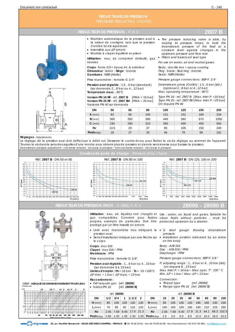
REDUCTEUR DE PRESSION - P. R. V. 2807 B
Maintien automatique de la pression aval à la valeur de consigne, tant que la pression d'entrée lui est supérieure.
Insensible aux ΔP amont Modèle à clapet équilibré et piston
Utilisation : eau, air comprimé déshuilé, gaz neutres
Corps : fonte GS + époxy int. & extérieur Obturateur : laiton - Siège : bronze Garnitures : NBR (Nitrile)
Prise manomètre : femelle G 1/4"
Pression aval réglable : 1.5…6 bar (standard) (sur demande 2…8 bar ou 4…12 bar) Température maxi. : 80°C
Version PN 16 RF - réf. 2807 B [PMA = 16 bar] Version PN 25 RF - réf. 2807 BH [PMA = 25 bar] Variante PN 40 sur demande
The pressure reducing valve is able, by varying its pressure drops, to hold the downstream pressure of the fluid at a constant level against changes in the upstream pressure and flow rate
Piston and balanced seat type
For use on water, air and neutral gases
Body : ductile iron + epoxy coating Plug : brass - Seal ring : bronze Seals : NBR (Nitrile)
Pressure gauge connections : BSP F. 1/4"
Downstream press. (Outlet) : 1.5...6 bar (std.) (optional 2...8 bat or 4...12 bar) Max. operating temperature : 80°C
Type PN 16 - ref. 2807 B [Max. Inlet P. =16 bar] Type PN 25 - ref. 2807 BH [Max. Inlet P. =25 bar] On request PN 40
DN 50 65 80 100 125 150 200 A (mm) 83 90 100 121 152 169 234 B (mm) 300 350 390 440 560 670 1050 C (mm) 230 290 310 350 400 450 550
Kv 13.5 20 37 80 105 150 240 Poids (kg) 18 27 33 46 78 99 191
Réglages - Adjustments Le réglage de la pression aval doit s'effectuer à débit nul. Desserrer le contre-écrou pour libérer la vis de réglage au sommet de l'appareil. Tourner la vis dans le sens des aiguilles d'une montre pour obtenir plus de pression et dans le sens inverse pour baisser la pression. Downstream pressure adjustment : clockwise rotation : increase in pressure / anti-clockwise rotation : decrease in pressure.
Courbes de perte de charge - Pressure drop charts Réf. 2807 B - DN 50 et 65
Réf. 2807 B - DN 80 et 100
Réf. 2807 B - DN 125, 150 et 200
REDUCTEUR DE PRESSION INOX - S. STEEL P. R. V. 28090 - 28090 B
DÉBIT : ABAQUE DE DIMENSIONNEMENT POUR L'EAU
Utilisation : eau, air, liquides non chargés et gaz compatibles. Convient pour fluides propres, exempts de particules. Doit être protégé par un filtre installé en amont.
Livré avec manomètre inox indiquant la pression aval
Sens d'installation indiqué par une flèche sur le corps
Corps : inox 316 Clapet : inox 316 / FPM Membrane : FPM
Prise manomètre : femelle G 1/8"
Pression aval réglable : 1…6 bar ou 4…10 bar (sur demande 8 à 13 bar) Limites d'emploi : Ps = 16 bar - Ts = -15 +100°C ΔP mini. = 1 bar / ΔP maxi. = 13 bar
Raccordement : FxF taraudé gaz [réf. 28090] brides PN 16 [réf. 28090 B]
Use : water, air, liquid and gases. Suitable for clean fluids without particles ; must be protected upstream by a strainer.
S. steel gauge showing downstream pressure
Installation position indicated by an arrow on the body
Body : AISI 316 Disc : AISI 316 / FPM Diaphragm : FPM
Pressure gauge connections : BSP F. 1/8 "
P. adjusting range : 1…6 bar or 4…10 bar (std) (on request 8…13 bar) Max. Inlet P. = 16 bar - Max. oper. T° : 100 ° C Min. ΔP = 1 bar / Max. ΔP = 13 bar
Connection : Thread type [ref. 28090] Flange type PN 16 [ref. 28090 B]
réf. 28090 réf. 28090 B DN 1/2 3/4 1 1-1/2 2 DN 15 20 25 40 50 65 80 100
H (mm) 85 105 105 130 130 H (mm) 85 105 105 130 185 185 230 230 L (mm) 70 85 92 115 120 L (mm) 150 150 150 190 190 210 225 250
Kv 2.05 7.69 9.40 17.9 21.3 Kv 2.05 7.69 9.40 17.9 21.3 64.1 68.3 102.5Poids (kg) 0.80 1.00 1.05 2.30 2.50 Poids (kg) 2.0 3.0 5.0 8.0 12.0 16.0 18.0 25.0

Document non contractuel C - 141
33, av. Franklin Roosevelt - 69150 DÉCINES CHARPIEU - FRANCE - 04 78 58 34 81 - Fax 04 78 69 50 98 - Fax international +33 478 726 965 - [email protected]
SCHEMA THEORIQUE D’UN RESEAU VAPEUR SCHEMATIC OF A STEAM PRODUCTION CYCLE

Document non contractuel C - 142
33, av. Franklin Roosevelt - 69150 DÉCINES CHARPIEU - FRANCE - 04 78 58 34 81 - Fax 04 78 69 50 98 - Fax international +33 478 726 965 - [email protected]
REDUCTEURS DE PRESSION PRESSURE REDUCING VALVES
DETENDEUR-REGULATEUR POUR VAPEUR & AIR - P. R. V. FOR STEAM & AIR 2920
Détendeur-régulateur à action directe pour installations process de petite capacité
Exceptionnellement compact Les pièces en contact avec le fluide sont
entièrement en inox. Pression aval stable Débit élevé pour sa catégorie Réduction de la pression jusqu’à 30 : 1 Crépine incorporée
Raccordement taraudé gaz
Corps & couvercle : inox Internes : inox
Température maxi. Ts : 220°C Pression maxi. Ps : 16 bar
Plages de pressions : Amont 2…16 bar ; réglage aval 0.14…2 bar [mais pas moins que 1/30 de la pression amont] Amont 2…16 bar ; réglage aval 1.8…6 bar Amont 6…16 bar ; réglage aval 5.4…10 bar
La pression aval ne doit pas dépasser 90% de la pression amont.
Extremely compact pressure reducing valve for use on small process equipment
Exceptionally light and compact PRV All wetted parts made of stainless steel Stable secondary pressure High flow rate for its class Pressure reduction ratio of 30 : 1 Built-in screen ensures extended trouble-free
operation.
Connection : BSP threaded ends
Body & cover : stainless steel Trim : stainless steel
Max. temperature : 220°C Max. pressure : 16 bar
Pressure range : Inlet 2…16 bar ; set pressure 0.14…2 bar [but not less than 1/30 of primary pressure] Inlet 2…16 bar ; set pressure 1.8…6 bar Inlet 6…16 bar ; set pressure 5.4…10 bar
The downstream pressure should not exceed 90% of the upstream pressure.
DN H (mm) L (mm) Poids (kg) 1/2 185 95 1.9
3/4 185 95 1.8
1 185 95 1.8
DETENDEUR-REGULATEUR DE PRESSION POUR VAPEUR - STEAM P. R. V. 2916 B
Détendeur-régulateur de pression à fonctionnement piloté, pour une efficacité maximale des systèmes process (vapeur)
Le piston sphérique à réalignement automatique absorbant les coups et le régulateur piloté de pointe maintiennent la précision de la pression aval, même dans des conditions difficiles.
La crépine de grande surface pour la soupape-pilote permet un fonctionnement sans problème.
Le tube de prise d’impulsion interne en aval évite le recours à un tube externe.
DN ≥ 65 équipés d’un silencieux
Raccordement à brides PN 16
Corps : fonte GS Internes : inox
Température maxi. Ts : 220°C Pression maxi. Ps : 16 bar Pression de réglage : 2…16 bar [entre 10-84 % de la pression amont, mais avec une pression minimale de 0.3 bar]
Débit mini. réglable : 5 % du débit nominal Débit mini. réglable : (10 % pour DN ≥ 65) Variante : corps en inox
Pilot operated pressure reducing valve for accurate control in process steam system
Self-aligning shock-absorbing spherical
piston and advanced pilot regulator designs maintain secondary steam pressure accuracy, even during adverse process conditions.
Large surface area integral screen for pilot valve extends trouble-free service
Internal secondary pressure-sensing channel makes external sensing line unnecessary.
DN ≥ 65 with silencer for noise reduction
Flanged connection PN 16
Body : ductile iron Trim : s. steel
Max. temperature : 220°C Max. pressure : 16 bar Adjustable pressure range : 2...16 bar [within 10-84 % of primary pressure, but with a minimum pressure of 0.3 bar]
Minimum flow rate : 5 % of rated flow rate (10 % for DN ≥ 65) Alternate : s. steel body
DN H (mm) L (mm) Poids (kg) 25 357 160 13
32 385 180 19
40 385 200 20
50 412 230 27
65 554 290 57
80 554 310 58
100 633 350 87
150 810 480 180 21

Document non contractuel C - 143
33, av. Franklin Roosevelt - 69150 DÉCINES CHARPIEU - FRANCE - 04 78 58 34 81 - Fax 04 78 69 50 98 - Fax international +33 478 726 965 - [email protected]
REDUCTEURS DE PRESSION PRESSURE REDUCING VALVES
REDUCTEUR DE PRESSION PN 25 - P. R. V. 2910
Détendeur-régulateur à action directe Crépine-filtre incorporée et soufflet inox 316
à haute durabilité Appareil non étanche en ligne, prévoir un
robinet d'isolement en amont. Montage en position horizontale Applications : vapeur, air comprimé et gaz
Corps : fonte GS Tige & siège : inox Ressort : acier chromé + silicone
Température de service : -10°C à +210°C Pression maxi. Ps : 19 bar Plages de détente : 0.14…1.7 bar 1.4…4 bar 3.5…8.6 bar
L’installation d’un filtre en Y en amont est recommandée.
Direct acting pressure reducing valve With integral screen & high durability
bellows Valve non tight in line Operating in horizontal position Applications : steam, compressed air and
gases
Body : ductile iron Stem & seat : stainless steel Spring : chromium plated steel + silicone
Working temperature : -10°C to +210°C Max. pressure : 19 bar Adjustable set pressure ranges : 0.14…1.7 bar 1.4…4 bar 3.5…8.6 bar
Installation of a Y strainer upstream is recommended.
DN 1/2 3/4 1 A (mm) 85 98 110 B (mm) 126 126 126 C (mm) 65 65 65
Poids (kg) 2.0 2.05 2.3
DETENDEUR AUTOMOTEUR PN 16 - SELF-OPERATED P. R. V. 2910 B
Détendeur automoteur à action directe et proportionnelle
Applications industrielles : postes de détente vapeur, air, eau et tous fluides compatibles.
Le réglage de la pression aval se fait par manœuvre sur le ressort
Raccordement à brides PN 16
Corps : fonte GS Internes : inox 316 Ressort et servomoteur : acier Membrane : EPDM renforcé
Limites d’emploi vapeur : 200°C / 13 bar Limites d’emploi eau : 120°C / 16 bar
Variantes : versions acier & inox à brides PN 40
Direct and proportional acting self-operated reducing valve
Industrial applications such as steam reducing systems, air, water...
The downstream pressure can be set by
operating the spring.
Flanged connection PN 16
Body : ductile iron Trim : AISI 316 Spring & actuator : c. steel Diaphragm : reinforced EPDM
Working limits steam : 200°C / 13 bar Working limits water : 120°C / 16 bar
Alternates : c. steel & s. steel types, flanges PN 40
DN 15 20 25 32 40 50 65 80 100 A (mm) 150 150 160 180 200 230 290 310 350 B (mm) 48 53 58 70 75 83 93 100 100 C (mm) 480 490 495 505 525 555 570 635 650
Servomoteur (D x E) Plages
de détente (bar)
D20 (136 x 91 mm) - 8…20 bar D10 D10 (136 x 91 mm) - 1…10 bar
D8 (180 x 70 mm) - 1.2 à 6 bar D4 D4 (180 x 70 mm) - 1…4 bar
D1 (270 x 75 mm) - 0.2…1.5 bar Poids (kg) 19 19 20 24 23 27 40 50 65
SEPARATEUR PN 40 - STEAM SEPARATOR PN 40 2981 B
Elimination des particules d'eau, d'huile et de poussières dans les tuyauteries de distribution de vapeur et d'air comprimé. Le séparateur permet d'obtenir un fluide propre et protège les équipements sensibles en aval : détendeurs, vannes de régulation, instrumentation. Purge incorporée en point bas Construction acier (variante tout inox)
Raccordement à brides PN 40
Limites d’emploi : vapeur : 250°C / 32 bar Limites d’emploi : air : 20°C / 40 bar
Pression d’épreuve hydraulique : 60 bar
Removal of entrained contaminants ; extracts nearly all moisture & solids - The remaining fluid is clean & dry, allowing improved & maintained performance. Applications : steam, compressed air Drain outlet below condensate level C. steel execution (alternate s. steel)
Flanged connection PN 40
Working limits : steam : 250°C / 32 bar Working limits : air : 20°C / 40 bar
Hydraulic test pressure : 60 bar

Document non contractuel C - 144
33, av. Franklin Roosevelt - 69150 DÉCINES CHARPIEU - FRANCE - 04 78 58 34 81 - Fax 04 78 69 50 98 - Fax international +33 478 726 965 - [email protected]
REGULATEURS DE PRESSION PRESSURE REGULATORS
REGULATEUR DE PRESSION - PRESSURE REGULATOR 316 L # 1/4" 290114
Version à piston
Régulateur de pression : à membrane : pression maxi. de Sortie 15 bar à piston : pression maxi. de Sortie 50 bar
Avec ou sans système de décharge selon fluide.
Raccordement : FxF 1/4" gaz (NPT sur demande) Sortie manomètre : 1/4" gaz
Construction : Corps, couvercle & internes : inox 316 L Ressorts : inox 302
Température de service : -20°C +60°C Pression maxi. Ps : 50 bar
Variantes : raccordement 3/8" (gaz ou NPT) à brides version ATEX
Pressure regulator with : diaphragm for Outlet pressure up to 15 bar piston for Outlet pressure up to 50 bar
Relieving to exhaust the overpressure, compressed air only
Connection : FxF 1/4" BSP (NPT on request) Gauge port BSP 1/4"
Materials : Body, bonnet & trim : AISI 316 L Springs : AISI 302
Working temperature : -20°C +60°C Max. pressure : 50 bar
Alternates : 3/8" connection flanged ends ATEX complying version
Type Membrane Piston Pression Entrée (bar) 30 50 50 Pression Sortie (bar) 0.2...1.5 0.3...3 0.8...8 1.5...15 1.5...15 3...30 5...50
Courbes de débit : version à membrane Courbes de débit : version à piston
REGULATEUR DE PRESSION - PRESSURE REGULATOR 316 L # 1/2" 290121
Version
à membrane
Régulateur de pression : à membrane : pression maxi. de Sortie 15 bar à piston : pression maxi. de Sortie 50 bar
Avec ou sans système de décharge selon fluide.
Raccordement : FxF 1/2" gaz (NPT sur demande) Sortie manomètre 1/4" gaz
Construction : Corps, couvercle & internes : inox 316 L Ressorts : inox 302
Température de service : -20°C à +60°C Pression maxi. Ps : 50 bar
Variantes : raccordement 3/4" (gaz ou NPT) à brides version ATEX
Pressure regulator with : diaphragm for Outlet pressure up to 15 bar piston for Outlet pressure up to 50 bar
Relieving to exhaust the overpressure, compressed air only
Connection : FxF 1/2" BSP (NPT on request) Gauge port BSP 1/4"
Materials : Body, bonnet & trim : AISI 316 L Springs : AISI 302
Working temperature : -20°C to +60°C Max. pressure : 50 bar
Alternates : 3/4" connection Alternates : flanged ends Alternates : ATEX complying version
Type Membrane Piston Pression Entrée (bar) 30 50 50 Pression Sortie (bar) 0.2...1.5 0.3...3 0.8...8 1.5...15 1.5...15 3...30 5...50
Courbes de débit : version à membrane Courbes de débit : version à piston

Document non contractuel C - 145
33, av. Franklin Roosevelt - 69150 DÉCINES CHARPIEU - FRANCE - 04 78 58 34 81 - Fax 04 78 69 50 98 - Fax international +33 478 726 965 - [email protected]
REGULATEURS DE PRESSION PRESSURE REGULATORS
REGULATEUR DE PRESSION - PRESSURE REGULATOR 316 L # 1" 290123
Version à membrane
Régulateur de pression : à membrane : pression maxi. de Sortie 15 bar à piston : pression maxi de sortie 50 bar
Avec ou sans système de décharge selon fluide
Raccordement : FxF 1" gaz (NPT sur demande) Sortie manomètre 1/4" gaz
Construction : Corps, couvercle et internes : inox 316 L Ressort intérieur : inox 302
Température de service : -20°C +60°C Pression maxi. Ps : 50 bar
Variantes : raccordement 3/4" (gaz ou NPT) à brides version ATEX
Pressure regulator with : diaphragm for Outlet pressure up to 15 bar piston for Outlet pressure up to 50 bar
Relieving to exhaust the overpressure, compressed air only
Connection : FxF 1" BSP (NPT on request) Gauge port BSP 1/4"
Materials : Body, bonnet & trim : AISI 316 L Internal spring : AISI 302
Working temperature : -20°C +60°C Max. pressure : 50 bar
Alternates : 3/4" connection Alternates : flanged ends Alternates : ATEX complying version
Type Membrane Piston
Pression Entrée (bar) 30 50 50
Pression Sortie (bar) 0.2 - 1.5 0.3 - 3 0.8 - 8 1.5 - 15 1.5 - 15 3 - 30 5 - 50
Courbes de débit : version à membrane Courbes de débit : version à piston
REGULATEUR DE PRESSION - PRESSURE REGULATOR 316 L # 1-1/2" 290130
Régulateur de pression à piston
Avec ou sans système de décharge selon fluide
Raccordement : FxF 1-1/2" gaz (NPT sur demande) Sortie manomètre G 1/4"
Construction : Corps, couvercle et internes : inox 316 L Ressort intérieur : inox 302 Ressort de réglage : acier nickelé
Température de service : -20°C à +60°C Pression maxi. Ps : 50 bar
Variantes : raccordement 2" (gaz ou NPT) à brides version ATEX
Pressure regulator with piston
Relieving to exhaust the overpressure, compressed air only
Connection : FxF 1-1/2" BSP (NPT on request) Gauge port BSP 1/4"
Materials : Body, bonnet and trim : 316 L Internal spring : AISI 302 Adjusting spring : steel nickel plated
Working temperature : -20°C to +60°C Max. pressure : 50 bar
Alternates : 2" connection (BSP or NPT) Alternates : flanged ends Alternates : ATEX complying version
Pression Entrée (bar) 50
Pression Sortie (bar) 0.2 - 1.5 0.3 - 3 0.8 - 8 1.5 - 15 1.5 - 15 3 - 30 5 - 50
Courbes de débit : Ps 30 bar Courbes de débit : Ps 50 bar
Document non contractuel C - 146
33, av. Franklin Roosevelt - 69150 DÉCINES CHARPIEU - FRANCE - 04 78 58 34 81 - Fax 04 78 69 50 98 - Fax international +33 478 726 965 - [email protected]
REGULATEURS DE PRESSION PRESSURE REGULATORS
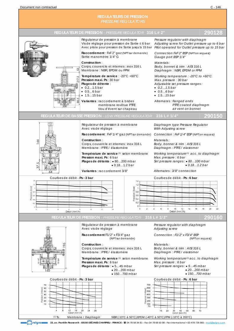
REGULATEUR DE PRESSION - PRESSURE REGULATOR 316 L # 2" 290128
Régulateur de pression à membrane Vis de réglage pour pression de Sortie ≤ 6 bar Avec pilote pour pression de Sortie jusqu'à 15 bar
Raccordement : FxF 2" gaz (NPT sur demande) Sortie manomètre 1/4" G
Construction : Corps, couvercle et internes : inox 316 L Membrane : NBR, EPDM ou FPM
Température de service : -20°C +60°C Pression maxi. Ps : 30 bar Plages de détente : 0.2…1.5 bar 0.5…6 bar 1.5…15 bar
Variantes : raccordement à brides Variantes : membrane revêtue PTFE Variantes : trou d'évent sur chapeau
Pressure regulator with diaphragm Adjusting screw for Outlet pressure up to 6 bar Pilot operated for Outlet pressure up to 15 bar
Connection FxF 2" BSP (NPT on request) Gauge port BSP 1/4"
Materials : Body, bonnet & trim : AISI 316 L Diaphragm : NBR, EPDM or FPM
Working temperature : -20°C to +60°C Max. pressure : 30 bar Adjustable set pressure ranges : 0.2…1.5 bar 0.5…6 bar 1.5…15 bar
Alternates : flanged ends Alternates : PTFE coated diaphragm Alternates : air vent on bonnet
REGULATEUR DE BASSE PRESSION - LOW PRESSURE REGULATOR 316 L # 1/4" 290150
Régulateur de pression à membrane Avec vis de réglage
Raccordement : FxF 1/4" gaz (NPT sur demande)
Construction : Corps, couvercle et internes : inox 316 L Membrane : PTFE / élastomère
Température de service (1) selon membrane Pression maxi. Ps : 6 bar Plages de détente : ● 80…200 mbar ● 0.18…1.2 bar
Variantes : raccordement 3/8"
Diaphragm type Pressure Regulator With Adjusting screw
Connection : FxF 1/4" BSP (NPT on request)
Materials : Body, bonnet & trim : AISI 316 L Diaphragm : PTFE / elastomer
Working temperature(1) acc. to diaphragm Max. pressure : 6 bar Set pressure ranges : ● 80…100 mbar ● 0.18…1.2 bar
Alternates : 3/8" connection
Courbes de débit - Ps : 3 bar
Courbes de débit - Ps : 6 bar
REGULATEUR DE PRESSION - PRESSURE REGULATOR 316 L # 1/2" 290160
Régulateur de pression à membrane Avec vis de réglage
Raccordement F1/2" x F3/4" gaz (NPT sur demande)
Construction : Corps, couvercle et internes : inox 316 L Membrane : PTFE / élastomère
Température de service (1) selon membrane Pression maxi. Ps : 6 bar Plages de détente : ● 5…45 mbar ● 20…200 mbar ● 150…700 mbar
Pressure regulator with diaphragm Adjusting screw
Connection : F1/2" x F3/4" BSP (NPT on request)
Materials : Body, bonnet & trim : AISI 316 L Diaphragm : PTFE / elastomer
Working temperature(1) acc. to diaphragm Max. pressure : 6 bar Set pressure ranges : ● 5…45 mbar ● 20…200 mbar ● 150…700 mbar
Courbes de débit - Ps : 3 bar
Courbes de débit - Ps : 6 bar
(1) Ts : Membrane / Diaphragm NBR (-10°C à 50°C) EPDM (-40°C à 50°C) FPM (-10°C à 200°C)

Document non contractuel C - 147
33, av. Franklin Roosevelt - 69150 DÉCINES CHARPIEU - FRANCE - 04 78 58 34 81 - Fax 04 78 69 50 98 - Fax international +33 478 726 965 - [email protected]
REGULATEURS DE PRESSION PRESSURE REGULATORS
REGULATEUR DE PRESSION - PRESSURE REGULATOR 316 L # 1" 290180
Courbes de débit - Ps : 6 bar
Régulateur de pression haute sensibilité avec membrane de grande dimension. Avec vis de réglage Deux prises pour manomètre F 1/4" gaz Raccordement : FxF 1" gaz (NPT sur demande) Corps, couvercle et internes : inox 316 L Membrane : PTFE / élastomère Température de service (1) selon membrane Pression maxi. Ps : 6 bar Plages de détente : ● 20…50 mbar Plages de détente : ● 100…700 mbar Plages de détente : ● 0.6…6 bar
Diaphragm type Pressure regulator Large sized diaphragm for high sensitivity and accurate low pressure. Adjusting screw Two ports in body for gauge F 1/4" BSP Connection : FxF 1" BSP (NPT on request) Body, bonnet and trim : AISI 316 L Diaphragm : PTFE / elastomer Working temperature (1) acc. to diaphragm Max. pressure : 6 bar Set pressure ranges : ● 20…50 mbar Set pressure ranges : ● 100…700 mbar Set pressure ranges : ● 0.6…6 bar
REGULATEUR DE PRESSION - PRESSURE REGULATOR 316 L # 2" 290190
Régulateur de pression haute sensibilité avec membrane de grande dimension. Avec vis de réglage Deux prises pour manomètre F 1/4" gaz Raccordement : FxF 2" gaz (NPT sur demande) Corps, couvercle et internes : inox 316 L Membrane : PTFE / élastomère Température de service (1) selon membrane Pression maxi. Ps : 6 bar Plages de détente : ● 20…50 mbar Plages de détente : ● 50…150 mbar
Diaphragm type Pressure regulator Large sized diaphragm for high sensitivity and accurate low pressure. Adjusting screw Two ports in body for gauge F 1/4" BSP Connection : FxF 2" BSP (NPT on request) Body, bonnet and trim : AISI 316 L Diaphragm : PTFE / elastomer Working temperature (1) acc. to diaphragm Max. pressure : 6 bar Set pressure ranges : ● 20…50 mbar Set pressure ranges : ● 50…150 mbar
Plages de détente (mbar) 20 ÷ 50 50 ÷ 150 150 ÷ 300 0.3 ÷ 3
Débit (l. / sec. maxi.) 3 ÷ 35 4 ÷ 40 5 ÷ 60 180 ÷ 700
FILTRE INOX - S. STEEL FILTER 290 FIL
Conception tout inox 316 L Avec purge Joint O-ring élastomère Taux de filtration : 5 µ ou 50 µ Connexion standard taraudé gaz Température de service : -20°C +60°C Pression maxi. Ps : 50 bar
Material AISI 316 L Drain service Elastomer O-ring Filtration rate : 5 µ or 50 µ Standard BSP connection Working temperature : -20°C +60°C Max. pressure : 50 bar
DN A (mm)
B (mm)
C (mm)
Poids (kg)
1/4 65 116 13 1.6
1/2 80 130 22 2.0
3/4 80 130 22 2.0
1 100 165 26 5.0
1-1/2 200 200.5 51.5 15.2
2 200 200.5 51.5 15.2 (1) Ts : Membrane / Diaphragm NBR (-10°C à 50°C) EPDM (-40°C à 50°C) FPM (-10°C à 200°C)

Document non contractuel C - 148
33, av. Franklin Roosevelt - 69150 DÉCINES CHARPIEU - FRANCE - 04 78 58 34 81 - Fax 04 78 69 50 98 - Fax international +33 478 726 965 - [email protected]
GARNITURES DE NIVEAU TUBULAIRES ET A GLACES LEVEL GAUGES
GARNITURE DE NIVEAU TUBULAIRE PN 6 - LEVEL CONTROLLER 2611
Pour visualisation de niveau de liquides propres, non agressifs, basse pression et température ambiante
Pression maxi. Ps : 6 bar Température maxi. Ts : 80°C
Garniture : laiton [variante inox sur demande] Tube : Plexiglas transparent
Option : tube de protection laiton en U
Level indicator for clear and non-aggressive liquids, low pressure and ambient temperature
Max. pressure : 6 bar Max. temperature : 80°C
Body : brass [alternative : s. steel on request] Glass tube : transparent Plexiglas
Option : brass protection U tube
DN S (mm) H (mm) T (mm) [Ø tube Plexiglas] Poids (kg) 1/4 88 12 10 0.50 3/8 97 13 13 0.62 1/2 100 15 13 0.76 1/2 101 15 16 0.78 3/4 116 15 18 1.07 3/4 116 15 20 1.07
INDICATEURS DE NIVEAU A GLACE KLINGER - KLINGER GLASS LEVEL GAUGES 2650
Niveau à réflexion
Niveau à transparence
Niveaux à réflexion : l'indicateur comporte une seule glace dont la face en contact avec le fluide est striée (glace prismatique). Les indices de réfraction différents font apparaître la phase liquide en noir et la phase gaz en brillant argenté.
Limites d'utilisation : Process 400 bar ou 400°C maxi. Vapeur saturée 32 bar maxi.
Niveaux à transparence : la lecture de niveau se fait par transparence, le produit étant contenu entre deux glaces lisses.
Limites d'utilisation : Process 340 bar ou 400°C maxi. Vapeur saturée 180 bar
Corps : acier, inox, alliages spéciaux, plastiques Glaces : verre borosilicate Option : mica de protection
Entraxe avec mini. / maxi. à préciser Raccordement aux robinets par tubulures
Reflex type : level gauges consisting of a single glass with a ribbed surface (prismatic glass) in contact with the liquid. Because of different refractive indices, the liquid phase has a dark appearance and the gaseous phase a bright silvery appearance.
Working conditions : Process 400 bar or 400°C max. Saturated steam 32 bar max.
Transparent type : thru-vision reading : the fluid is contained between 2 glasses with smooth surfaces.
Working conditions : Process 340 bar or 400°C max. Saturated steam 180 bar max.
Body : c. steel, s. steel, alloys, plastics Glass : borosilicate Option : transparent mica
Distance between axes with mini. / max. to specify
Connection to cocks : nipples
ROBINETTERIE DE NIVEAU KLINGER - KLINGER GAUGE COCKS 2660
Robinet à boisseau cylindrique, à pointeau ou à piston
Raccordement : taraudé, à souder ou à brides
Classes de pression : PN 10 à PN 420 Classes de pression : classe 150 à 2500 lbs
Construction : acier, inox, alliages, plastiques
Cylindrical plug valve, needle valve or piston valve
Connection : threaded, SW or flanged
Pressure range : PN 10 to PN 420 Pressure range : class 150 to 2500 lbs
Materials : c. steel, s. steel, alloys, plastics
PIECES DE RECHANGE - SPARE PARTS 2670
glace prismatique
glace lisse
Glaces en verre borosilicate Type prismatique ou lisse Joint Klingerit ou graphite Mica de protection
Glasses : borosilicate Reflex or transparent Gaskets : Klingerit or graphite Mica glass
Dimensions des glaces type KLINGER - KLINGER type glass dimensions N° 0 I II III IV V VI VII VIII IX X
Longueur / Length L 95 115 140 165 190 220 250 280 320 340 370
Largeur / Width 30 mm (type A) ou 34 mm (types B & H)
Épaisseur / Thickness 17 mm (types A & B) ou 22 mm (type H)

Document non contractuel C - 149
33, av. Franklin Roosevelt - 69150 DÉCINES CHARPIEU - FRANCE - 04 78 58 34 81 - Fax 04 78 69 50 98 - Fax international +33 478 726 965 - [email protected]
CONTROLEURS DE CIRCULATION SIGHT GLASSES
CONTROLEUR DE CIRCULATION LAITON - BRASS SIGHT GLASS 28130
Contrôleur double glace avec bille mobile
Corps : laiton Glace : verre trempé Joint : fibre
Raccordement : F x F gaz Ps : 16 bar - Ts : 120°C
Double sided sight glass with floating ball
Body : brass Glass : tempered glass Seal : fiber
BSP F x F connection Max. pressure : 16 bar - Max. T° : 120°C
DN 1/2 3/4 1 1-1/4 1-1/2 2 H (mm) 80 90 92 112 118 140 L (mm) 95 100 107 126 137 170
Poids (kg) 1.08 1.22 1.3 2.4 2.7 5.00
CONTROLEUR DE CIRCULATION FONTE - C. I. SIGHT GLASS 28100
Contrôleur à double glace taraudé
Corps : fonte Glace : verre trempé Joint : PTFE
Raccordement : F x F gaz Ps : 16 bar - Ts : 180°C
Double sided sight glass - Screwed ends
Body : cast iron Glass : tempered glass Seal : PTFE
BSP F x F connection Max. pressure : 16 bar - Max. T° : 180°C
DN 1/2 3/4 1 1-1/4 1-1/2 2 A (mm) 75 90 90 120 120 140 B (mm) 60 66 73 102 102 116
Poids (kg) 0.62 0.80 1.00 2.1 2.1 2.9
CONTROLEUR DE CIRCULATION FONTE - C. I. SIGHT GLASS 28100 B
Contrôleur à double glace à brides
Corps : fonte Glace : verre trempé Joint : fibre
Raccordement : brides PN 16 Ps : 16 bar - Ts : 180°C
Double sided sight glass - Flanged ends
Body : cast iron Glass : tempered glass Seal : fiber
Connection : PN 16 flanges [1/2" to 10"] Max. pressure : 16 bar - Max. T° : 180°C
DN 15 20 25 32 40 50 65 80 100 125 150 200 250 F (mm) 95 105 115 140 150 165 185 200 220 250 285 340 405 L (mm) 130 150 160 180 200 230 290 310 350 400 480 600 730
Poids (kg) 2.9 3.5 4 6 6.5 9 13 15 17 - - - -
CONTROLEUR DE CIRCULATION ACIER - C. S. SIGHT GLASS 28150
Contrôleur à double glace taraudé
Corps : acier Glace : verre trempé Joint : fibre
Raccordement : F x F gaz Ps : 16 bar - Ts : 180°C
Double sided sight glass - Screwed ends
Body : cast steel Glass : tempered glass Seal : fiber
BSP F x F connection Max. pressure : 16 bar - Max. T° : 180°C
DN 1/2 3/4 1 A (mm) 105 105 110 B (mm) 71 71 71
Poids (kg) 1.1 1.1 1.23
CONTROLEUR DE CIRCULATION ACIER - C. S. SIGHT GLASS 28150 B
Contrôleur à double glace à brides
Corps : acier Glace : verre [150°C maxi.] Glace : pyrex [280°C maxi.] Joint : graphite
Raccordement : brides PN 16, PN 25 ou 40 Ps : 16 / 25 / 40 bar Ts : 150°C ou 280°C
Options : battant ou roue à ailettes brides ANSI B16.5
Double sided sight glass - Flanged ends
Body : cast steel Glass : soda lime [150°C max.] Glass : borosilicate [280°C max.] Seal : graphite
Flanged connection to DIN Max. pressure : 16 / 25 / 40 bar Max. temperature : 150°C or 280°C
Options : internal spinner or flap Option : flanges to ANSI B16.5
DN 15 20 25 32 40 50 65 80 100 125 150 200 250 D (mm) 95 105 115 140 150 165 185 200 220 250 285 340 405 D*(mm) - - - - - - - - 235 270 300 360/375 425/450 L (mm) 130 150 160 180 200 230 290 310 350 400 480 600 730
* selon PN 25 / PN 40

Document non contractuel C - 150
33, av. Franklin Roosevelt - 69150 DÉCINES CHARPIEU - FRANCE - 04 78 58 34 81 - Fax 04 78 69 50 98 - Fax international +33 478 726 965 - [email protected]
CONTROLEURS DE CIRCULATION SIGHT GLASSES
CONTROLEUR DE CIRCULATION INOX - S. STEEL SIGHT GLASS 28200
Contrôleur à double glace taraudé
Corps : inox 316 Glace : verre trempé Joint : PTFE
Raccordement : F x F gaz Ps : 16 bar - Ts : 180°C
Double sided sight glass - Screwed ends
Body : AISI 316 Glass : tempered glass Seal : PTFE
BSP Female connection 1/2" to 2" Max. pressure : 16 bar - Max. T° : 180°C
DN 1/2 3/4 1 1-1/4 1-1/2 2 H (mm) 108 108 119 125 135 170 L (mm) 71 71 71 100 102 120
De 1/2" à 1" : bride de glace circulaire Poids (kg) 1.1 1.1 1.23 2.8 2.8 4.1
CONTROLEUR DE CIRCULATION INOX - S. STEEL SIGHT GLASS 28200 B
Contrôleur à double glace à brides
Corps : inox 316 Glace : verre trempé Joint : PTFE
Raccordement : brides PN 16 Ps : 16 bar - Ts : 180°C
Double sided sight glass - Flanged ends
Body : AISI 316 Glass : tempered glass Seal : PTFE
Connection : PN 16 flanges [1/2" to 6"] Max. pressure : 16 bar - Max. T° : 180°C
DN 15 20 25 32 40 50 65 80 100 125 150 H (mm) 100 100 100 125 125 125 167 180 210 270 280 L (mm) 130 150 160 180 200 230 290 310 350 400 480
Poids (kg) 2.9 3.5 4 6 6.5 9 12 16 22 - -
CONTROLEUR DE CIRCULATION TUBULAIRE - TUBULAR TYPE SIGHT GLASS 28110 B
Contrôleur tubulaire
Manchon : verre borosilicate [= pyrex] Joint : Viton® ou PTFE Brides : inox
Raccordement à brides PN 10/16 Ps : 6 bar DN ≤100 # 4 bar DN ≥ 125 Ts : 200°C
Options : manchon anti-projection, brides ANSI, longueur sur mesure…
Tubular type sight glass
Glass tube : borosilicate [= pyrex] Seal : Viton® or PTFE Flanges : s. steel
PN 10/16 Flanged connection Max. press. : 6 bar DN ≤100 # 4 bar DN ≥ 125 Max. temperature : 200°C
Special designs : protection jacket, ANSI flanges, extra length…
DN 15 20 25 32 40 50 65 80 100 125 150 200 D(mm) 95 105 115 140 150 165 185 200 220 250 285 340 L (mm) 200 200 200 200 200 200 200 200 200 200 200 200
CONTROLEUR DE CIRCULATION CLAMP - STERILE VISUAL FLOW INDICATOR 28120 B
Contrôleur aseptique
Corps : inox 316 L [option Hastelloy] Manchon : pyrex Joint : EPDM [FDA]
Raccordement clamp
Etat de surface : Ra 0.50, 0.63 ou 0.75 µm avec électropolissage : 0.38, 0.50 ou 0.63 µm
Pharmaceutical sight glass
Body : 316 L [option : Hastelloy] Glass : borosilicate O-rings : EPDM [FDA]
Clamp connection
Surface finish : Ra 0.50, 0.63 or 0.75 µm with electropolishing : 0.38, 0.50 or 0.63 µm
DN 3/8 1/2 3/4 1 1-1/2 2 2-1/2 3 4 6 L (mm) 65 76 87 91 105 120 151 175 200 250
ØB (mm) 7.7 9.5 15.8 22.1 34.8 47.5 60.3 72.9 97.4 150.0 ØC (mm) 25.4 25.4 25.4 50.5 50.5 64.0 77.5 91.0 119.0 167.0 Ps (bar) 22.0 20.0 17.5 8.5 8.0 7.0 6.5 6.5 4.0 3.0
Poids (kg) 0.09 0.12 0.15 0.37 0.40 0.63 1.15 1.46 2.78 6.0
AUTRES CONTROLEURS DE CIRCULATION - OTHER SIGHT GLASS DESIGNS
Hautes pressions jusqu'à 160 bar High pressure up to 160 bar
Sans zone de rétention Straight line, without dead space
Viseurs circulaires Circular type

Document non contractuel C - 151
33, av. Franklin Roosevelt - 69150 DÉCINES CHARPIEU - FRANCE - 04 78 58 34 81 - Fax 04 78 69 50 98 - Fax international +33 478 726 965 - [email protected]
ISO 9001 VISEUR 3 PIECES MECA-INOX MECA-INOX 3-PIECE SIGHT GLASS
VISEUR CIRCULAIRE VC4 (GAMME PS4) - VC4 SIGHT GLASS (PS4 RANGE)
Pour fluides corrosifs, fluides utilisés en chimie, pharmacie et agroalimentaire
La cartouche est un ensemble vissé et précontraint ; viseur monté et testé en usine.
Pare-éclat rigide : des lumières permettent de constater le passage du fluide.
Le système de la bride tournante facilite l’alignement des embouts afin de positionner la visserie (gain de temps au montage de 30%).
Interchangeabilité avec le R.T.S. PS4
Corps, embouts & pare-éclat : inox 316 L Brides tournantes : inox 304 L Verre : Pyrex Joint de corps : PTFE
Température & pression : voir diagramme
For corrosive fluids, fluids used in chemicals, pharmaceuticals, food & beverage
The cartridge is a bolted assembly ; the sight glass is assembled and tested at the factory.
Glass protector made of stainless steel sheet : long laser - cutted holes allow seeing flow.
The system of the self-aligning flange features an easy alignment of end connections during installation (time saving : 30%).
Interchangeable with PS4 ball valve
Body, ends & protection : s. steel 316 L Body flanges : s. steel 304 L Glass : Pyrex Body gasket : PTFE
Temperature & pressure : see chart
RACCORDEMENT CONNECTION
PASSAGE INTÉGRAL FULL BORE
PASSAGE RÉDUIT REDUCED BORE
BW à souder en bout Butt weld ends réf. 4505 réf. 4506
SW à souder emboîté Socket weld ends réf. 4515 sur demande - on request
TG taraudé gaz BSP Fem. threaded ends réf. 4525 sur demande - on request
RF à brides Flanged ends sur demande - on request sur demande - on request
PASSAGE INTEGRAL Raccordements BW, SW, TG - FULL BORE BW, SW, BSP ends
DN ØA (mm) D (mm) G (mm) ØH (mm) Poids (kg) 08 1/4 11 65 20.4 56 0.36 12 3/8 11 65 20.4 56 0.37 15 1/2 14 70 24.4 63 0.46 20 3/4 21 85 31.6 80 0.94 25 1 25 100 41.4 88 1.14 32 1-1/4 32 110 48.2 104 1.83 40 1-1/2 38 125 56.2 117 2.36 50 2 50 150 71 148 5.0
PASSAGE REDUIT Raccordements BW, SW, TG - REDUCED BORE BW, SW, BSP ends
DN ØA (mm) D (mm) G (mm) ØH (mm) Poids (kg) 15 1/2 11 65 20.4 56 0.37 20 3/4 14 70 24.4 63 0.46 25 1 21 85 31.6 80 0.94 32 1-1/4 25 100 41.4 88 1.14 40 1-1/2 32 110 48.2 104 1.83 50 2 38 125 56.2 117 2.36 65 2-1/2 50 150 71 148 5.0
Diagramme Pression / Température - Pressure / Temperature chart