variability of surface quality of mdf boards · pdf fileacta facultatis xylologiae zvolen,...
TRANSCRIPT

ACTA FACULTATIS XYLOLOGIAE ZVOLEN, 59(1): 121−130, 2017
Zvolen, Technická univerzita vo Zvolene
DOI: 10.17423/afx.2017.59.1.12
121
VARIABILITY OF SURFACE QUALITY OF MDF BOARDS AT
NESTING MILLING ON CNC MACHINING CENTERS
Richard Kminiak – Adrian Banski
ABSTRACT
The article deals with the issue of nesting milling of agglomerated materials on CNC
machining centers. Specifically assess the quality of the surface around the perimeter of the
workpiece with the view of relative changes of feed speeds direction as a result of different
positions of tools and materials. Article based on experiments in which was at 5 axis CNC
machining center nesting milled 18 mm thick MDF board. In the milling process they were
used router bit with one or two reversible razor blades. The experiment was carried out at
manufacturer recommended intervals of cutting and feeding speeds and machining
strategies.
The findings of the experiment are presented via parameter arithmetic mean deviation
of the surface roughness Ra. Article points out that the relative change of cutting speed
direction affects this indicator. It notes that the change is average 3.4 microns in the router
bit with one reversible razor blade and 1.6 microns in router bit with two reversible razor
blades. Given discovery of point of view of perception of surface roughness by people can
be considered negligible but in exact perception cause a need for correcting the technological
parameters of the process.
Key words: machined surface inequalities, MDF machining, milling direction, nesting
milling, router bit with reversible razors.
INTRODUCTION
The application of CNC technology offers a variety of machining possibilities of the
given material. In machining of agglomerated materials, so called nesting milling is
becoming extremely popular. Nesting milling is process when workpiece is extracted from
the input material by router bits milling while distribution of the individual workpiece within
given material determinates optimization software and created surface is considered as final
and therefore no further working with exception of grinding is necessary (LASZEWICZ et al.
2013).
HIZIROGLU and KOSONKORN (2006), OČKAJOVÁ et al. (2016) state that the degree of
roughness of the surface of the MDF plays an important role, since all surface irregularities
may show through through a thin pad, reduce the final quality of the panel. MARIAN et al.
(1954), FAUST (1987) and RICHTER et al. (1995) in his work they showed that smooth
surfaces need relatively little primer and paint to cover better adhere to the surface.
As is apparent from the work GAFF et al. (2015) and SIKLIENKA et al. (2016). The
surface roughness can have the following causes:
122
Kinematic cause unevenness (waviness) lie in cycloid shape relative movement of the
cutting edge of the knife in the wood, which make absolutely flat surface rotary tool even
theoretically cannot reach.
Technological causes unevenness (roughness) consist for example. transection of
vessels or fibers, annual rings, moisture, conventional milling or climb milling, type of
wood, etc.
Technical causes of inequality lie in the precision setting of knives of the cutter head
(or. In precision grinding disc cutters to equal the average of all cutting edges) in the state of
wear of the cutting edge of the blade, of vibration and throwing of the milling tool. They are
expressed both in uprooting fibers (edge wear) and irregularities of ripples distance on a
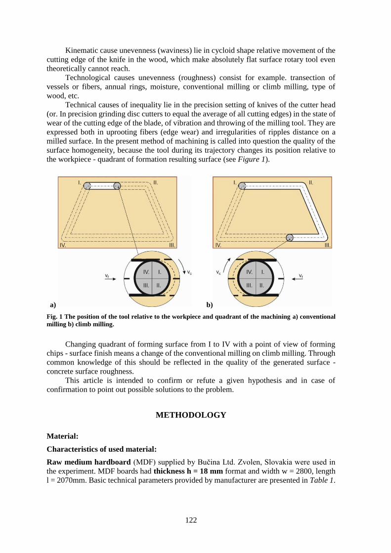
milled surface. In the present method of machining is called into question the quality of the
surface homogeneity, because the tool during its trajectory changes its position relative to
the workpiece - quadrant of formation resulting surface (see Figure 1).
a) b)
Fig. 1 The position of the tool relative to the workpiece and quadrant of the machining a) conventional
milling b) climb milling.
Changing quadrant of forming surface from I to IV with a point of view of forming
chips - surface finish means a change of the conventional milling on climb milling. Through
common knowledge of this should be reflected in the quality of the generated surface -
concrete surface roughness.
This article is intended to confirm or refute a given hypothesis and in case of
confirmation to point out possible solutions to the problem.
METHODOLOGY
Material:
Characteristics of used material:
Raw medium hardboard (MDF) supplied by Bučina Ltd. Zvolen, Slovakia were used in
the experiment. MDF boards had thickness h = 18 mm format and width w = 2800, length
l = 2070mm. Basic technical parameters provided by manufacturer are presented in Table 1.
123
Tab. 1 Technical parameters of raw medium-density fiberboard.
Property Test method Request
Thickness tolerance STN EN 324-1 ± 0,3 mm
Dimensions tolerance STN EN 324-1 ± 5,0 mm
Squareness tolerance STN EN 324-2 ± 2 mm·m1
Humidity STN EN 322 4 ÷ 11 %
Formaldehyde release STN EN 120 < 8 mg / 100 g a.s. samples
Thickness range > 6 >9 >12 >19 >30
< 9 <12 <19 <30 <45 (mm)
Bending strength STN EN 310 23 22 20 18 17 (MPa)
Tensile strength STN EN 319 0.65 0.60 0.55 0.55 0.50 (MPa)
Swelling after 24 hours STN EN 317 17 15 12 10 8 (%)
Modulus of elasticity STN EN 310 2800 2500 2200 2150 1900 (MPa)
Characteristics of the machine:
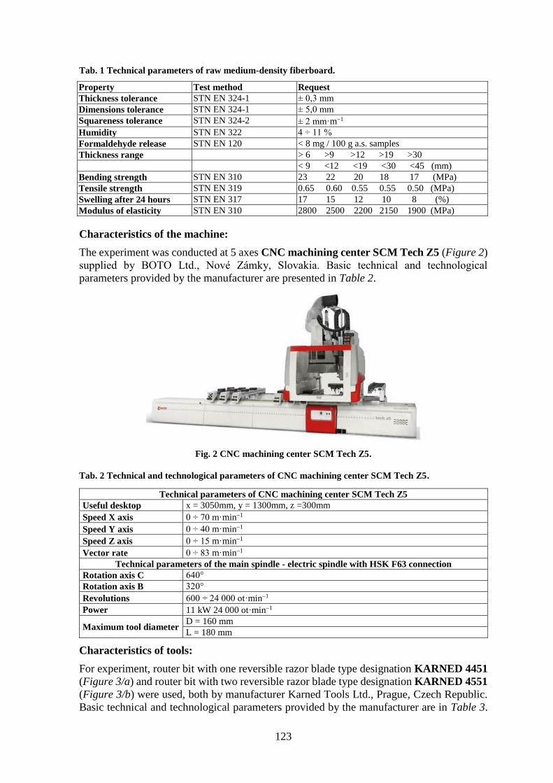
The experiment was conducted at 5 axes CNC machining center SCM Tech Z5 (Figure 2)
supplied by BOTO Ltd., Nové Zámky, Slovakia. Basic technical and technological
parameters provided by the manufacturer are presented in Table 2.
Fig. 2 CNC machining center SCM Tech Z5.
Tab. 2 Technical and technological parameters of CNC machining center SCM Tech Z5.
Technical parameters of CNC machining center SCM Tech Z5
Useful desktop x = 3050mm, y = 1300mm, z =300mm
Speed X axis 0 ÷ 70 m·min1
Speed Y axis 0 ÷ 40 m·min1
Speed Z axis 0 ÷ 15 m·min1
Vector rate 0 ÷ 83 m·min1
Technical parameters of the main spindle - electric spindle with HSK F63 connection
Rotation axis C 640°
Rotation axis B 320°
Revolutions 600 ÷ 24 000 ot·min1
Power 11 kW 24 000 ot·min1
Maximum tool diameter D = 160 mm
L = 180 mm
Characteristics of tools:
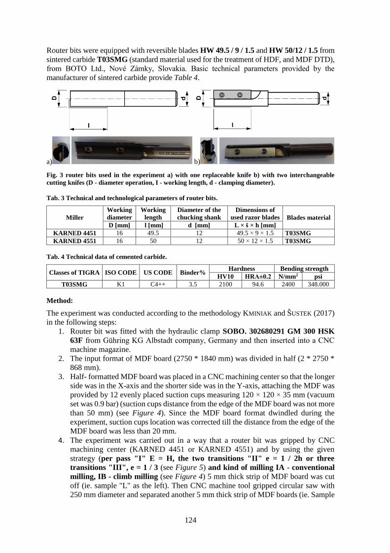
For experiment, router bit with one reversible razor blade type designation KARNED 4451
(Figure 3/a) and router bit with two reversible razor blade type designation KARNED 4551
(Figure 3/b) were used, both by manufacturer Karned Tools Ltd., Prague, Czech Republic.
Basic technical and technological parameters provided by the manufacturer are in Table 3.
124
Router bits were equipped with reversible blades HW 49.5 / 9 / 1.5 and HW 50/12 / 1.5 from
sintered carbide T03SMG (standard material used for the treatment of HDF, and MDF DTD),
from BOTO Ltd., Nové Zámky, Slovakia. Basic technical parameters provided by the
manufacturer of sintered carbide provide Table 4.
a) b)
Fig. 3 router bits used in the experiment a) with one replaceable knife b) with two interchangeable
cutting knifes (D - diameter operation, I - working length, d - clamping diameter).
Tab. 3 Technical and technological parameters of router bits.
Miller
Working
diameter
Working
length
Diameter of the
chucking shank
Dimensions of
used razor blades Blades material
D [mm] l [mm] d [mm] L × š × h [mm]
KARNED 4451 16 49.5 12 49.5 × 9 × 1.5 T03SMG
KARNED 4551 16 50 12 50 × 12 × 1.5 T03SMG
Tab. 4 Technical data of cemented carbide.
Classes of TIGRA ISO CODE US CODE Binder% Hardness Bending strength
HV10 HRA±0.2 N/mm2 psi
T03SMG K1 C4++ 3.5 2100 94.6 2400 348.000
Method:
The experiment was conducted according to the methodology KMINIAK and ŠUSTEK (2017)
in the following steps:
1. Router bit was fitted with the hydraulic clamp SOBO. 302680291 GM 300 HSK
63F from Gühring KG Albstadt company, Germany and then inserted into a CNC
machine magazine.
2. The input format of MDF board (2750 * 1840 mm) was divided in half (2 * 2750 *
868 mm).
3. Half- formatted MDF board was placed in a CNC machining center so that the longer
side was in the X-axis and the shorter side was in the Y-axis, attaching the MDF was
provided by 12 evenly placed suction cups measuring 120 × 120 × 35 mm (vacuum
set was 0.9 bar) (suction cups distance from the edge of the MDF board was not more
than 50 mm) (see Figure 4). Since the MDF board format dwindled during the
experiment, suction cups location was corrected till the distance from the edge of the
MDF board was less than 20 mm.
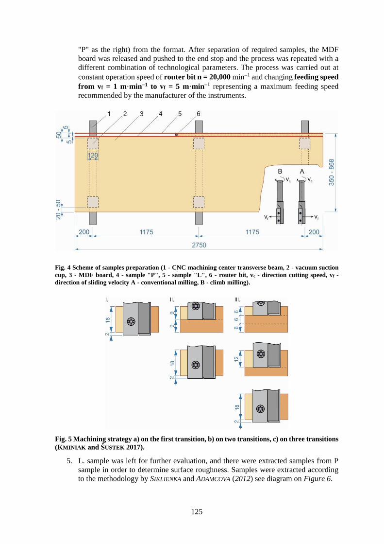
4. The experiment was carried out in a way that a router bit was gripped by CNC
machining center (KARNED 4451 or KARNED 4551) and by using the given
strategy (per pass "I" E = H, the two transitions "II" e = 1 / 2h or three
transitions "III", e = 1 / 3 (see Figure 5) and kind of milling IA - conventional
milling, IB - climb milling (see Figure 4) 5 mm thick strip of MDF board was cut
off (ie. sample "L" as the left). Then CNC machine tool gripped circular saw with
250 mm diameter and separated another 5 mm thick strip of MDF boards (ie. Sample
125
"P" as the right) from the format. After separation of required samples, the MDF
board was released and pushed to the end stop and the process was repeated with a
different combination of technological parameters. The process was carried out at
constant operation speed of router bit n = 20,000 min1 and changing feeding speed
from vf = 1 m·min1 to vf = 5 m·min1 representing a maximum feeding speed
recommended by the manufacturer of the instruments.
Fig. 4 Scheme of samples preparation (1 - CNC machining center transverse beam, 2 - vacuum suction
cup, 3 - MDF board, 4 - sample "P", 5 - sample "L", 6 - router bit, vc - direction cutting speed, vf -
direction of sliding velocity A - conventional milling, B - climb milling).
Fig. 5 Machining strategy a) on the first transition, b) on two transitions, c) on three transitions
(KMINIAK and ŠUSTEK 2017).
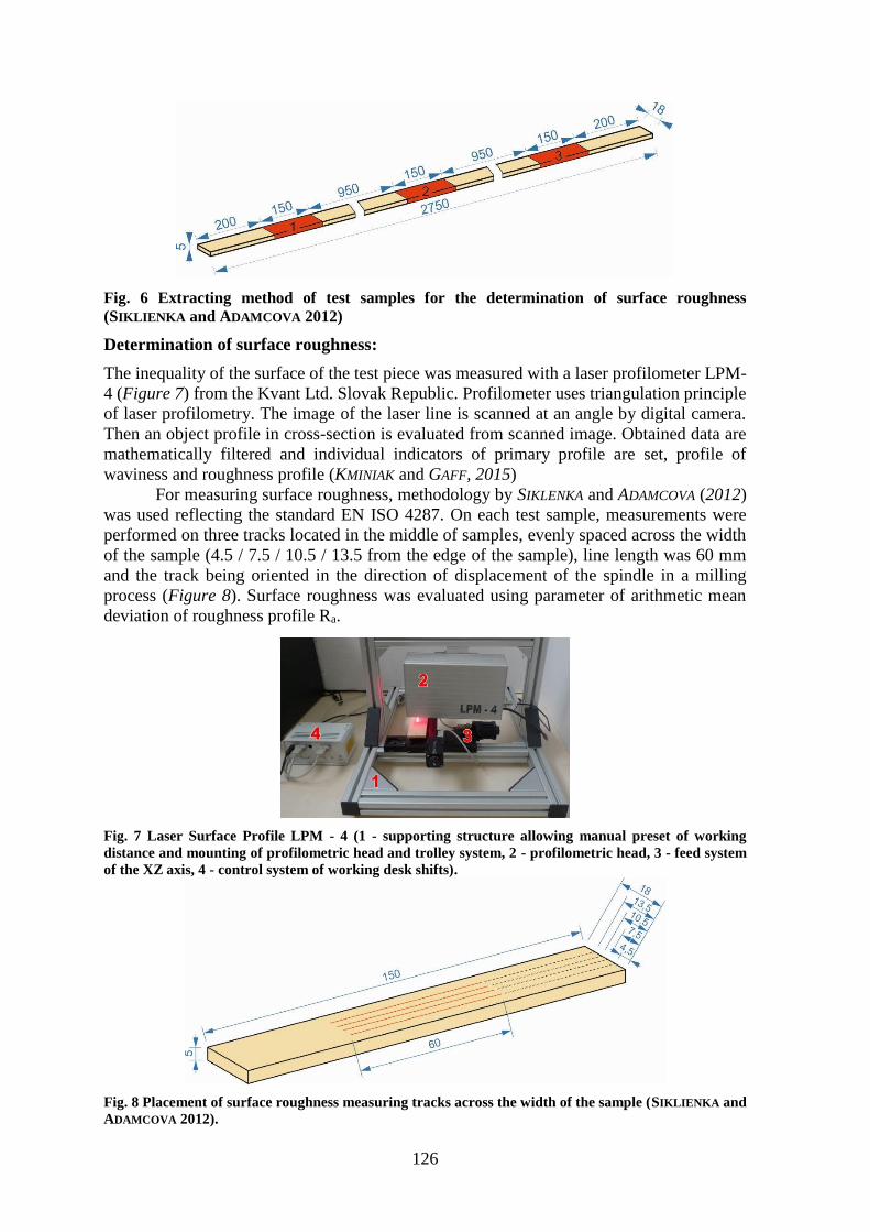
5. L. sample was left for further evaluation, and there were extracted samples from P
sample in order to determine surface roughness. Samples were extracted according
to the methodology by SIKLIENKA and ADAMCOVA (2012) see diagram on Figure 6.
126
Fig. 6 Extracting method of test samples for the determination of surface roughness
(SIKLIENKA and ADAMCOVA 2012)
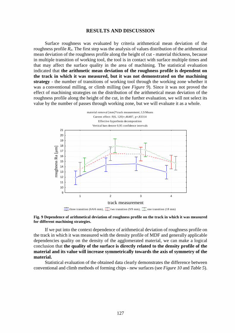
Determination of surface roughness:
The inequality of the surface of the test piece was measured with a laser profilometer LPM-
4 (Figure 7) from the Kvant Ltd. Slovak Republic. Profilometer uses triangulation principle
of laser profilometry. The image of the laser line is scanned at an angle by digital camera.
Then an object profile in cross-section is evaluated from scanned image. Obtained data are
mathematically filtered and individual indicators of primary profile are set, profile of
waviness and roughness profile (KMINIAK and GAFF, 2015)
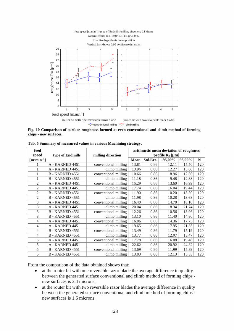
For measuring surface roughness, methodology by SIKLENKA and ADAMCOVA (2012)
was used reflecting the standard EN ISO 4287. On each test sample, measurements were
performed on three tracks located in the middle of samples, evenly spaced across the width
of the sample (4.5 / 7.5 / 10.5 / 13.5 from the edge of the sample), line length was 60 mm
and the track being oriented in the direction of displacement of the spindle in a milling
process (Figure 8). Surface roughness was evaluated using parameter of arithmetic mean
deviation of roughness profile Ra.
Fig. 7 Laser Surface Profile LPM - 4 (1 - supporting structure allowing manual preset of working
distance and mounting of profilometric head and trolley system, 2 - profilometric head, 3 - feed system
of the XZ axis, 4 - control system of working desk shifts).
Fig. 8 Placement of surface roughness measuring tracks across the width of the sample (SIKLIENKA and
ADAMCOVA 2012).
127
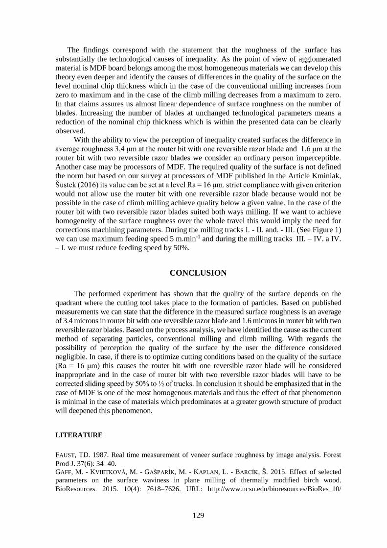
RESULTS AND DISCUSSION
Surface roughness was evaluated by criteria arithmetical mean deviation of the
roughness profile Ra. The first step was the analysis of values distribution of the arithmetical
mean deviation of the roughness profile along the height of cut - material thickness, because
in multiple transition of working tool, the tool is in contact with surface multiple times and
that may affect the surface quality in the area of machining. The statistical evaluation
indicated that the arithmetic mean deviation of the roughness profile is dependent on
the track in which it was measured, but it was not demonstrated on the machining
strategy - the number of transitions of working tool through the working zone whether it
was a conventional milling, or climb milling (see Figure 9). Since it was not proved the
effect of machining strategies on the distribution of the arithmetical mean deviation of the
roughness profile along the height of the cut, in the further evaluation, we will not select its
value by the number of passes through working zone, but we will evaluate it as a whole.
Fig. 9 Dependence of arithmetical deviation of roughness profile on the track in which it was measured
for different machining strategies.
If we put into the context dependence of arithmetical deviation of roughness profile on
the track in which it was measured with the density profile of MDF and generally applicable
dependencies quality on the density of the agglomerated material, we can make a logical
conclusion that the quality of the surface is directly related to the density profile of the
material and its value will increase symmetrically towards the axis of symmetry of the
material.
Statistical evaluation of the obtained data clearly demonstrates the difference between
conventional and climb methods of forming chips - new surfaces (see Figure 10 and Table 5).
material removal [mm]*track measurement; LS Means
Current effect: F(6, 120)=,46487, p=,83314
Effective hypothesis decomposition
Vertical bars denote 0,95 confidence intervals
three transition (6/6/6 mm), two transition (9/9 mm), one transition (18 mm)
1 2 3 4
track measurement
9
10
11
12
13
14
15
16
17
18
19
20
21
rou
ghn
ess
Ra
[μm]
128
Fig. 10 Comparison of surface roughness formed at even conventional and climb method of forming
chips - new surfaces.
Tab. 5 Summary of measured values in various Machining strategy.
feed
speed
[m·min1]
type of Endmills milling direction
arithmetic mean deviation of roughness
profile Ra [μm]
Mean Std.Err. -95,00% 95,00% N
1 A - KARNED 4451 conventional milling 13.81 0.86 12.11 15.50 120
1 A - KARNED 4451 climb milling 13.96 0.86 12.27 15.66 120
1 B - KARNED 4551 conventional milling 10.66 0.86 8.96 12.36 120
1 B - KARNED 4551 climb milling 11.18 0.86 9.48 12.88 120
2 A - KARNED 4451 conventional milling 15.29 0.86 13.60 16.99 120
2 A - KARNED 4451 climb milling 17.74 0.86 16.04 19.44 120
2 B - KARNED 4551 conventional milling 11.90 0.86 10.20 13.59 120
2 B - KARNED 4551 climb milling 11.98 0.86 10.28 13.68 120
3 A - KARNED 4451 conventional milling 16.40 0.86 14.70 18.10 120
3 A - KARNED 4451 climb milling 20.04 0.86 18.34 21.74 120
3 B - KARNED 4551 conventional milling 12.26 0.86 10.56 13.96 120
3 B - KARNED 4551 climb milling 13.10 0.86 11.40 14.80 120
4 A - KARNED 4451 conventional milling 16.06 0.86 14.36 17.75 120
4 A - KARNED 4451 climb milling 19.65 0.86 17.95 21.35 120
4 B - KARNED 4551 conventional milling 13.49 0.86 11.79 15.19 120
4 B - KARNED 4551 climb milling 13.77 0.86 12.07 15.47 120
5 A - KARNED 4451 conventional milling 17.78 0.86 16.08 19.48 120
5 A - KARNED 4451 climb milling 22.62 0.86 20.92 24.32 120
5 B - KARNED 4551 conventional milling 13.69 0.86 11.99 15.39 120
5 B - KARNED 4551 climb milling 13.83 0.86 12.13 15.53 120
From the comparison of the data obtained shows that:
at the router bit with one reversible razor blade the average difference in quality
between the generated surface conventional and climb method of forming chips -
new surfaces is 3.4 microns.
at the router bit with two reversible razor blades the average difference in quality
between the generated surface conventional and climb method of forming chips -
new surfaces is 1.6 microns.
feed speed [m.min-1]*type of Endmills*milling direction; LS Means
Current effect: F(4, 180)=1,7114, p=,14937
Effective hypothesis decomposition
Vertical bars denote 0,95 confidence intervals
conventional milling, climb milling
router bit with one reversible razor blade
1 2 3 4 5
6
8
10
12
14
16
18
20
22
24
26ro
ughnes
s R
a [μm]
router bit with two reversible razor blades
1 2 3 4 5
feed speed [m.min-1]
129
The findings correspond with the statement that the roughness of the surface has
substantially the technological causes of inequality. As the point of view of agglomerated
material is MDF board belongs among the most homogeneous materials we can develop this
theory even deeper and identify the causes of differences in the quality of the surface on the
level nominal chip thickness which in the case of the conventional milling increases from
zero to maximum and in the case of the climb milling decreases from a maximum to zero.
In that claims assures us almost linear dependence of surface roughness on the number of
blades. Increasing the number of blades at unchanged technological parameters means a
reduction of the nominal chip thickness which is within the presented data can be clearly
observed.
With the ability to view the perception of inequality created surfaces the difference in
average roughness 3,4 μm at the router bit with one reversible razor blade and 1,6 μm at the
router bit with two reversible razor blades we consider an ordinary person imperceptible.
Another case may be processors of MDF. The required quality of the surface is not defined
the norm but based on our survey at processors of MDF published in the Article Kminiak,
Šustek (2016) its value can be set at a level Ra = 16 μm. strict compliance with given criterion
would not allow use the router bit with one reversible razor blade because would not be
possible in the case of climb milling achieve quality below a given value. In the case of the
router bit with two reversible razor blades suited both ways milling. If we want to achieve
homogeneity of the surface roughness over the whole travel this would imply the need for
corrections machining parameters. During the milling tracks I. - II. and. - III. (See Figure 1)
we can use maximum feeding speed 5 m.min-1 and during the milling tracks III. – IV. a IV.
– I. we must reduce feeding speed by 50%.
CONCLUSION
The performed experiment has shown that the quality of the surface depends on the
quadrant where the cutting tool takes place to the formation of particles. Based on published
measurements we can state that the difference in the measured surface roughness is an average
of 3.4 microns in router bit with one reversible razor blade and 1.6 microns in router bit with two
reversible razor blades. Based on the process analysis, we have identified the cause as the current
method of separating particles, conventional milling and climb milling. With regards the
possibility of perception the quality of the surface by the user the difference considered
negligible. In case, if there is to optimize cutting conditions based on the quality of the surface
(Ra = 16 μm) this causes the router bit with one reversible razor blade will be considered
inappropriate and in the case of router bit with two reversible razor blades will have to be
corrected sliding speed by 50% to ½ of trucks. In conclusion it should be emphasized that in the
case of MDF is one of the most homogenous materials and thus the effect of that phenomenon
is minimal in the case of materials which predominates at a greater growth structure of product
will deepened this phenomenon.
LITERATURE
FAUST, TD. 1987. Real time measurement of veneer surface roughness by image analysis. Forest
Prod J. 37(6): 3440.
GAFF, M. - KVIETKOVÁ, M. - GAŠPARÍK, M. - KAPLAN, L. - BARCÍK, Š. 2015. Effect of selected
parameters on the surface waviness in plane milling of thermally modified birch wood.
BioResources. 2015. 10(4): 76187626. URL: http://www.ncsu.edu/bioresources/BioRes_10/
130
BioRes_10_4_7618_Gaff_KGKB_Effect_Selected_Parameters_Surface%20waviness_Milling_Bir
ch_7644.pdf. Project no. B05/15. WOS.
HIZIROGLU, S., KOSONKORN, P. 2006. Evaluation of surface roughness of Thai medium density
fiberboard. Build Environ 41: 527–533.
KMINIAK, R. - GAFF, M. 2015. Roughness of surface created by transversal sawing of spruce, beech,
and oak wood. BioResources. 2015. 10(2): 28732887. URL: http://www.ncsu.edu/bioresources/
BioRes_10/BioRes_10_2_2873_Kminiak_G_Surface_Unevenness_Created_Transversal_Sawing_
6794.pdf.
KMINIAK, R. - ŠUSTEK, J. 2016. The suitability of repeated machining in nesting milling on CNC
machining centers. In Chip and chipless woodworking processes 2016: 10th international science
conference, September 810, 2016, Zvolen : Technical University in Zvolen. 2016, s. 101114.
LASZEWICZ, K. - GÓRSKI, J. - WILKOWSKI, J. 2013. Long-term accuracy of MDF milling process—
development of adaptive control system corresponding to progression of tool wear. Eur. J. Wood
Prod. (2013) 71: 383. doi:10.1007/s00107-013-0679-2
MARIAN, JE., STUMBO, DA., MAXEY, CW. 1958. Surface texture of wood as related to glue-joint
strength. Forest Prod. J. (12): 345351.
OČKAJOVÁ, A., KUČERKA, M., KRIŠŤÁK, Ľ., RUŽIAK, I., GAFF, M. 2016. Efficiency of sanding belts
for beech and oak sanding. In Bioresources. Raleigh: North Carolina State university. ISSN 1930-
2126. Vol. 11, no. 2, pp. 5242-5254.
Očkajová, A., Kučerka, M. 2009. Granular analysis of dust particles from profiling and sanding
process of MDF. In Woodworking techniques : 3rd International Scientific Conference - Zagreb,
Croatia : Faculty of Forestry, 187-192. ISBN 978-953-292-009-3
RICHTER, K., FEIST, WC., KNABE, MT. 1995. The effect of surface roughness on the performance of
finishes. Part 1 Roughness characterization and strain performance. Forest Prod J. 45(7/8): 9197.
SIKLIENKA, M. - ADAMCOVÁ, E. 2012. Výskum vplyvu materiálu reverzibilných nožov stopkových
nástrojov na kvalitu opracovaného povrchu MDF. In Chip and chipless woodworking processes 2012
: 8th international science conference, September 68, 2012, Zvolen : Technical University in
Zvolen. 2012, s. 315323. ISBN 978-80-228-2385-2.
SIKLIENKA, M. - JANDA, P. - JANKECH, A. 2016. The influence of milling heads on the quality of
created surface. Acta Facultatis Xylologiae Zvolen. 2016. (2): 8188. ISSN 1336-3824.
ACKNOWLEDGEMENT
This work was supported by VEGA Grant No. 1/0725/16 “Prediction of the quality of the generated
surface during milling solid wood by razor endmills using CNC milling machines.”
AUTHORS ADDRESS
Ing. Richard Kminiak, PhD.
Ing. Adrián Banski. PhD.
Technical University in Zvolen
Faculty of Wood Sciences and Technology
Department of Woodworking
T. G. Masaryka 24
960 53 Zvolen
Slovakia