variable-area flowmeter k12 operating instructions€¦ · heinrichs messtechnik k12 operating...
TRANSCRIPT

Variable-Area Flowmeter
K12
Operating Instructions
Heinrichs Messtechnik K12 Operating Instructions
Page 2 of 21
Contents
1 IDENTIFICATION ........................................................................................................................ 4
1.1 Supplier/manufacturer ............................. ............................................................................ 4
1.2 Product type ...................................... ................................................................................... 4
1.3 Issue date ........................................ ...................................................................................... 4
1.4 Version no. ....................................... ..................................................................................... 4
2 APPLICATIONS ...................................... .................................................................................... 4
2.1 K12 ......................................................................................................................................... 4
2.2 K12-..V / N c/w differential pressure regulator ... ............................................................... 4
3 OPERATIONAL MODE AND SYSTEM DESIGN K12 ............ ................................................... 4
3.1 K12 system design ................................. .............................................................................. 4
3.2 Measuring principle for K12-…V / N ................ ................................................................... 5
3.3 K12-..V / N system design ......................... .......................................................................... 5
4 INPUT .......................................................................................................................................... 5
4.1 Measured variable ................................. ............................................................................... 5
4.2 Measuring range (lower-range and upper-range values ) ................................................. 5
5 ELECTRICAL OUTPUT (OPTION) ........................ .................................................................... 6
5.1 Ad-on limit switches Type RC 10/15-14-XX, Manufactu rer Pepperl & Fuchs ................. 6
5.2 Ad-on limit switches Type N7R**A, Manufacturer ifm electronic ................................... 6
6 MEASURING ACCURACY ................................ ......................................................................... 6
6.1 Reference conditions .............................. ............................................................................. 6
6.2 Measured error .................................... ................................................................................. 6
6.3 Repeatability ..................................... .................................................................................... 6
6.4 Influence of ambient temperature .................. .................................................................... 6
6.5 Influence of fluid temperature..................... ........................................................................ 6
7 CONDITIONS OF USE ............................................................................................................... 6
7.1 Mounting / start-up ............................... ................................................................................ 6
7.2 Ambient conditions ................................ .............................................................................. 7 7.2.1 Ambient temperature ranges ............................................................................................ 7 7.2.2 Storage temperature ......................................................................................................... 7 7.2.3 Climatic category .............................................................................................................. 7 7.2.4 Degree of protection ......................................................................................................... 7 7.2.5 Shock resistance/vibration resistance .............................................................................. 7 7.2.6 Electromagnetic compatibility ........................................................................................... 7
7.3 Fluid conditions .................................. ................................................................................. 7 7.3.1 Fluid temperature ranges .................................................................................................. 7 7.3.2 Fluid pressure limit Max. 16 bar (20°C) ........... ................................................................. 7 7.3.3 Inlet and outlet sections .................................................................................................... 7 7.3.4 Physical state .................................................................................................................... 7 7.3.5 Pressure for gas measurement......................................................................................... 7 7.3.6 Pressure loss .................................................................................................................... 7
8 CONSTRUCTION DETAILS .............................. ......................................................................... 8
8.1 Construction/dimensions K12 ....................... ..................................................................... 8
8.2 Design / dimensions / operating details V / N ( op tion diff. pressure regulator) .......... 9 8.2.1 Dimension drawing K12-...V with conn. ¼“ NPT (F) as regulator c/w constant inlet pressure ........................................................................................................................................ 10

K12 Operating Instructions Heinrichs Messtechnik
Page 3 of 21
8.2.2 Dimension drawing K12-…N with conn. ¼“ NPT (F) as regulator c/w constant outlet pressure ........................................................................................................................................ 10
8.3 Weights ........................................... .................................................................................... 10
8.4 Materials ......................................... ..................................................................................... 10
8.5 Process connection ................................ ........................................................................... 11
9 ELECTRICAL CONNECTION FOR LIMIT TRANSDUCER OPTION . ..................................... 11
10 INDICATOR UNIT ..................................................................................................................... 11
11 USE IN HAZARDOUS AREAS ............................ ..................................................................... 12
11.1 Atmospheric Conditions ............................ ....................................................................... 12
11.2 Electrostatic charge of non-conductive parts....... .......................................................... 12 11.2.1 Ground connection .......................................................................................................... 12
11.3 Mechanical strength ............................... ........................................................................... 12
11.4 Without electrical equipment ...................... ...................................................................... 12
11.5 With limit transducer ............................. ............................................................................ 13
12 CE MARK ........................................... ....................................................................................... 13
13 AVAILABLE ACCESSORIES ............................. ..................................................................... 13
14 ORDER INFORMATION ........................................................................................................... 13
15 STANDARDS AND DIRECTIVES .......................... .................................................................. 13
16 SAFETY INSTRUCTIONS ........................................................................................................ 13
16.1 Intended use ...................................... ................................................................................. 13
16.2 Installation, start-up and operating personnel..... ........................................................... 14
17 PACKAGING, MOUNTING AND SHIPMENT .................. ........................................................ 14
18 MAINTENANCE ....................................... ................................................................................. 14
ATTENTION ........................................................................................................................................... 14
REPLACING THE MEASURING CONE ...................... ......................................................................... 14
REMOVAL: .......................................... .................................................................................................. 14
INSTALLATION: ..................................... ............................................................................................... 14
19 RETURNING DEVICES FOR REPAIR AND SERVICE .......... ................................................. 15
20 MODEL CODE .......................................................................................................................... 16
21 DECONTAMINATION CERTIFICATE FOR DEVICE CLEANING ... ........................................ 17
22 EC TYPE EXAMINATION CERTIFICATE OF THE LIMIT TRANSD UCER ............................. 18
22.1 Manufacturer Pepperl & Fuchs ...................... ................................................................... 18
22.2 Manufacturer ifm electronic ....................... ....................................................................... 18
23 DECLARATION OF CONFORMITY ......................... ................................................................ 19
KONFORMITÄTSERKLÄRUNG ............................. ................................................................. 19
ANHANG N ZUR KONFORMITÄTSERKLÄRUNG ................ ................................................. 20
ANNEX N OF THE DECLARATION OF CONFORMITY ...................................................................... 20
NO. 16.4132.01 ....................................................................................................................................... 20
ANHANG X ZUR KONFORMITÄTSERKLÄRUNG ................ ................................................. 21
ANNEX X OF THE DECLARATION OF CONFORMITY ...................................................................... 21
NO. 16.4132.01 ....................................................................................................................................... 21

Heinrichs Messtechnik K12 Operating Instructions
Page 4 of 21
1 Identification
1.1 Supplier/manufacturer Heinrichs Messtechnik GmbH Robert-Perthel-Str. 9 ⋅ D-50739 Cologne Phone +49 (221) 49708 - 0 Fax +49 (221) 49708 - 178 Internet: http://www.heinrichs.eu E-Mail: mailto:[email protected]
1.2 Product type Miniature flowmeter based on the float principle K12 mounting length 125 mm
1.3 Issue date 27.07.2017
1.4 Version no. K12_BA_17.01_en.doc
2 Applications
2.1 K12 The flowmeter can be used for measuring the flow of liquid and gaseous products in pipes. It shows the current flow quantity in volume or mass per unit in time. Applications: Measuring the flow of liquid and gaseous products in pipes as well as dosing, bubbling through, superim-posing, monitoring, regulating and controlling them.
2.2 K12-..V / N c/w differential pressure regulator The flowmeter can be used for stabilizing set flow quantities of liquid and gaseous products in pipes. The set quantity is kept constant regardless of pressure changes during product inflow for type K12-..V or of a pressure change during product outflow for type K12-..N. Applications: Constant dosing, level measurement in open and closed containers, N2 superposition of combustible media Caution: The devices should be used with the greatest possible caution to measure potentially hazard-ous liquids and (especially) gases. Precautionary measures must be taken to protect personnel and equipment from any potential danger or damage due to glass-tube breakage. The plant operator is fully responsible for using the devices. Where possible, we recommend the use of metal devices such as type KDS.
3 Operational mode and system design K12 Float principle: The product flows through the meter vertically from the bottom to the top. The height of the float in the measuring tube is a measure of the flow quantity. The float is in equilibrium between the buoyant force of the flowing liquid and the counteracting force of gravity on the float. The measured value is displayed on the measuring-tube scale with the upper edge or the indicator edge of the float (ball).
3.1 K12 system design The meter consists of a conical measuring tube made of glass containing a float that can move vertically. The height of the float in the measuring tube reproduces the calibrated flow quantities on the measuring tube.

K12 Operating Instructions Heinrichs Messtechnik
Page 5 of 21
3.2 Measuring principle for K12-…V / N Differential pressure: The diaphragm of the controller is in a state of equilibrium when the pressure conditions are the same on both sides. The pressure on the input side is determined by the pressure of the product; the pressure on the output side is determined by the pressure drop of the setting valve of the flowmeter. If either the inlet or outlet pressure changes, the change in pressure is compensated by the built-in dia-phragm valve - thus maintaining a constant set flow rate. Important: The controller can only regulate inlet or outlet pressure fluctuations. Steady pressure condi-tions must prevail on the other side.
3.3 K12-..V / N system design The unit consists of a K12 variable-area flowmeter, equipped with a diaphragm differential pressure flow controller. The variable-area flowmeter consists of a device fitting with an integrated measuring tube made of glass that contains a vertically movable float and the valve for setting the flow rate. The differential pressure flow controller is made of stainless steel and consists of a diaphragm made of Viton or PTFE and a compensating valve made of stainless steel. For gaseous products, two versions are available:
• K12-...V for a constant inlet pressure and a variable outlet pressure • K12-...N for a constant outlet pressure and a variable inlet pressure
For liquids, both versions can be used; however, the K12-...V version should be preferred.
4 Input
4.1 Measured variable Volume flow
4.2 Measuring range (lower-range and upper-range va lues) Measuring span water 20 °C K12: Smallest measuring range: 0.02-0.25 l/h water Largest measuring range: 16-160 l/h water Measuring span air 20°C, 1,2 bar abs. K12 Smallest measuring range: 0.5-5,0 Nl/h air Largest measuring range: 500-5000 Nl/h air
Measuring /controlling range for K12-..V / N Span: 10-100% Smallest measuring/controlling range 16-160 l/h water 0,5-5 Nl/h air Largest measuring/controlling range 16-160 l/h water 500-5000 Nl/h air
Measuring ranges water 20 °C Measuring ranges air 1,2 bar abs. 20 °C Float st.st. 1.4401 (SS316) Float st.st. 1.4401 (SS316)
Range N°
Water l/h
ø Float (mm)
ø Valve seat (mm)
Press. loss
(mbar)
Range N°
Air l/h
ø Float (mm)
ø Valve seat (mm)
Press. loss
(mbar) 17 0,25-2,5 4 1,2 10 07 0,5-5 4 1,2 15 20 0,5-5 4 1,2 20 09 0,8-8 4 1,2 15 25 1,2-12 6 2,8 10 13 1,6-16 4 1,2 15 28 2,5-25 6 2,8 20 21 4-40 4 1,2 20 30 4-40 6 2,8 30 24 6-60 4 1,2 25 35 6-60 6 2,8 80 29 10-100 6 2,8 15 39* 10-100 6 2,8 125 32 25-250 6 2,8 15 40* 12-120 6 3,4 200 37 50-500 6 2,8 15 41* 16-160 6 3,4 200 42 80-800 6 2,8 20
46 100-1000 6 2,8 25 51 180-1800 6 2,8 80
57* 240-2400 6 2,8 125
61* 300-3000 6 2,8 150
64* 400-4000 6 3,4 200
68* 500-5000 6 3,4 200 All ranges at fully opened valve * Limited adjustment range of the contact / contact can only be adjusted as min. contact
Measuring range table

Heinrichs Messtechnik K12 Operating Instructions
Page 6 of 21
5 Electrical output (option) 1 or 2 inductive limit switches, mono- or bistable
5.1 Ad-on limit switches Type RC 10/15-14-XX, Manuf acturer Pepperl & Fuchs Monostable Type RC 10/15-14-N0 Bistable Type RC 10/15-14-N3 Ex-Marking PTB 99 ATEX 2128 X,
II 2G Ex ia IIC T6
5.2 Ad-on limit switches Type N7R**A, Manufacturer ifm electronic Monostable Typ N7R28A (Inside diameter 10 mm) N7R30A (Inside diameter 15 mm) Bistable Typ N7R29A (Inside diameter 10 mm) N7R31A (Inside diameter 15 mm) Ex-Marking BVS 08 ATEX E026, IECEx BVS 09.0016 II 1G Ga Ex ia IIC T4/T5/T6, II 1D Ex iaD 20 T125°C When installing electrical equipment in hazardous a reas please pay attention to the conditions specified in the approval certificate.
6 Measuring accuracy
6.1 Reference conditions Water 20°C (air 20°C ; 1,2 bar abs.)
6.2 Measured error
K12 ± 2,5% FS qG 50 acc. VDE/VDI 3513 Bl.2 K12-…V / N (option diff.pressure regulator) Meas. error/system deviation ± 3% / ± 5% FS
6.3 Repeatability K12 ± 1.0 % FS K12-…V / N ± 1.5 % / 2,5 % FS
6.4 Influence of ambient temperature none
6.5 Influence of fluid temperature Deviations in fluid temperature from the temperature observed during calibration can result in a propor-tional display fault because of the corresponding change in density. Temperature-related changes in vis-cosity will cause a non-linear display fault.
7 Conditions of use The VDI/VDE guidelines must be observed. The devices can be used for: - liquid products that are sufficiently free-flowing, are free of solids, do not bond and do not tend to
settle. - gases with linear flow behavior and an adequate inlet pressure. K12-..V/N: The minimum differential inlet and outlet pressures must be 350 mbar. Please refer to the instructions for potentially ha zardous products in Section 2.2 .
7.1 Mounting / start-up When starting up the flowmeter, the following points must be observed: - The variable-area flow meter must be installed perpendicularly (direction of flow from the bottom to
the top).
K12 Operating Instructions Heinrichs Messtechnik
Page 7 of 21
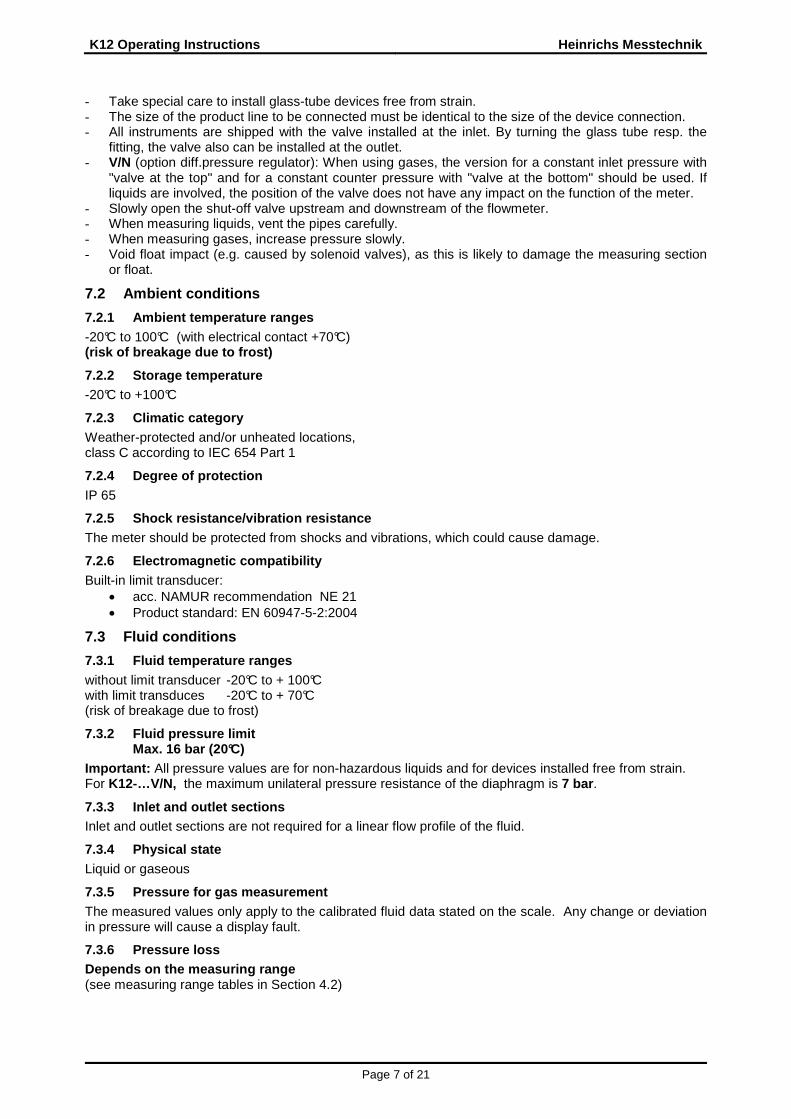
- Take special care to install glass-tube devices free from strain. - The size of the product line to be connected must be identical to the size of the device connection. - All instruments are shipped with the valve installed at the inlet. By turning the glass tube resp. the
fitting, the valve also can be installed at the outlet. - V/N (option diff.pressure regulator): When using gases, the version for a constant inlet pressure with
"valve at the top" and for a constant counter pressure with "valve at the bottom" should be used. If liquids are involved, the position of the valve does not have any impact on the function of the meter.
- Slowly open the shut-off valve upstream and downstream of the flowmeter. - When measuring liquids, vent the pipes carefully. - When measuring gases, increase pressure slowly. - Void float impact (e.g. caused by solenoid valves), as this is likely to damage the measuring section
or float.
7.2 Ambient conditions
7.2.1 Ambient temperature ranges -20°C to 100°C (with electrical contact +70°C) (risk of breakage due to frost)
7.2.2 Storage temperature -20°C to +100°C
7.2.3 Climatic category Weather-protected and/or unheated locations, class C according to IEC 654 Part 1
7.2.4 Degree of protection IP 65
7.2.5 Shock resistance/vibration resistance The meter should be protected from shocks and vibrations, which could cause damage.
7.2.6 Electromagnetic compatibility Built-in limit transducer:
• acc. NAMUR recommendation NE 21 • Product standard: EN 60947-5-2:2004
7.3 Fluid conditions
7.3.1 Fluid temperature ranges without limit transducer -20°C to + 100°C with limit transduces -20°C to + 70°C (risk of breakage due to frost)
7.3.2 Fluid pressure limit Max. 16 bar (20°C)
Important: All pressure values are for non-hazardous liquids and for devices installed free from strain. For K12-…V/N, the maximum unilateral pressure resistance of the diaphragm is 7 bar .
7.3.3 Inlet and outlet sections Inlet and outlet sections are not required for a linear flow profile of the fluid.
7.3.4 Physical state Liquid or gaseous
7.3.5 Pressure for gas measurement The measured values only apply to the calibrated fluid data stated on the scale. Any change or deviation in pressure will cause a display fault.
7.3.6 Pressure loss Depends on the measuring range (see measuring range tables in Section 4.2)
Heinrichs Messtechnik K12 Operating Instructions
Page 8 of 21
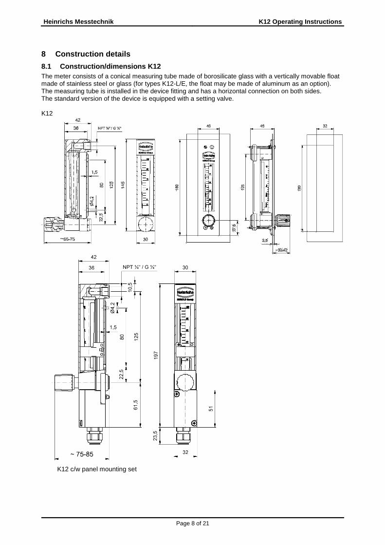
8 Construction details
8.1 Construction/dimensions K12 The meter consists of a conical measuring tube made of borosilicate glass with a vertically movable float made of stainless steel or glass (for types K12-L/E, the float may be made of aluminum as an option). The measuring tube is installed in the device fitting and has a horizontal connection on both sides. The standard version of the device is equipped with a setting valve. K12
K12 c/w panel mounting set

K12 Operating Instructions Heinrichs Messtechnik
Page 9 of 21
8.2 Design / dimensions / operating details V / N ( option diff. pressure regulator) Differential pressure regulators are used to achieve constant flow values at variable inlet and outlet pres-sures. � Differential pressure regulators are not pressure reduction valves
The measuring device constist of variable area flowmeter with control valve and mounted differential pressure regulator. The flow amount will be adjusted via the integrated adjusting valve. The max.one side pressure resistance of the regulator membrane is 7 bar. If the operating pressure ex-ceeds 7 bar, the control valve must not be fully closed as this leads into overstressing the membrane. IMPORTANT OPERATION DETAILS � The installation of any valve before the inlet and outlet of the instrument shall be avoided � Initial operation / start up of the process only with opened control valve � When operating any gas the inlet pressure shall be increased slowly to avoid strong pressure
peaks � Any operation of the instrument trough any solenoid valve shall be avoided, this will prevent
the float will be thrown upwards heavily. � For the operation of the regulator minimum inlet pressure are required.
Regulator with constant outlet pressure: 350 mbar Regulator with constant inlet pressure: 350 mbar.

Heinrichs Messtechnik K12 Operating Instructions
Page 10 of 21
8.2.1 Dimension drawing K12-...V with conn. ¼“ NPT (F) as regulator c/w constant inlet pressure
8.2.2 Dimension drawing K12-…N with conn. ¼“ NPT (F ) as regulator c/w constant outlet pressure
8.3 Weights K12 0.46 kg K12-…V/N 0.80 kg
8.4 Materials Fitting, connections, setting valve: 1.4404 / 1.4571 (SS316L / SS316 TI), seals viton/PTFE (option) Float 1.4401(SS316), Hoses PA Controller/control pipes: st.st. 1.4301 (SS304) Diaphragm: Viton or PTFE
¼“ NPT
connections ¼“ NPT female
¼“ NPT
¼“ NPT
K12 Operating Instructions Heinrichs Messtechnik
Page 11 of 21
Wiring diagram for 2 limit transducers
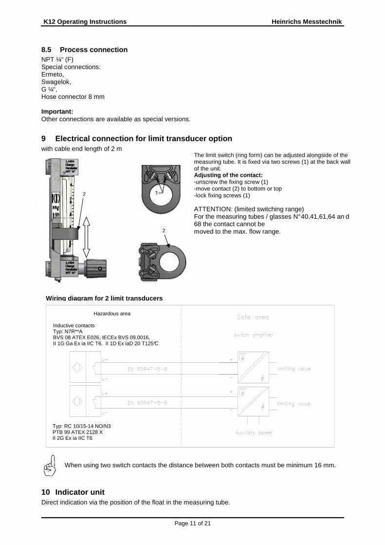
8.5 Process connection NPT ¼“ (F) Special connections: Ermeto, Swagelok, G ¼“, Hose connector 8 mm Important: Other connections are available as special versions.
9 Electrical connection for limit transducer option with cable end length of 2 m
When using two switch contacts the distance between both contacts must be minimum 16 mm.
10 Indicator unit Direct indication via the position of the float in the measuring tube.
The limit switch (ring form) can be adjusted alongside of the measuring tube. It is fixed via two screws (1) at the back wall of the unit. Adjusting of the contact: -unscrew the fixing screw (1) -move contact (2) to bottom or top -lock fixing screws (1) ATTENTION: (limited switching range) For the measuring tubes / glasses N° 40,41,61,64 an d 68 the contact cannot be moved to the max. flow range.
Typ: RC 10/15-14 NO/N3 PTB 99 ATEX 2128 X II 2G Ex ia IIC T6
Hazardous area Inductive contacts Typ: N7R**A BVS 08 ATEX E026, IECEx BVS 09.0016, II 1G Ga Ex ia IIC T6, II 1D Ex iaD 20 T125°C
2
2

Heinrichs Messtechnik K12 Operating Instructions
Page 12 of 21
11 Use in hazardous areas Only devices with ex marking may be operated within the explosive atmospheres range.
11.1 Atmospheric Conditions Atmospheric conditionsIn accordance with EN 1127, a “potentially explosive atmosphere“ is defined as a mixture of air and combustible gases, vapour, mist or dust under atmospheric conditions. Such conditions are defined in EN 13463-1, para. 1, with values Tatm = -20 °C to +60 °C and P atm = 0.8 to 1.1 bar. Outside this range, safety parameters for most ignition sources are not available. Usually, variable-area flow meters operate under operating conditions outside the atmospheric conditions of 0.8 to 1.1 bar. Irrespective of the zone classification –safety parameters of explosion protection – are basically not applicable to the inside of the measuring tube. Therefore operation with combustible products is only allowed if a potentially explosive air mixture is not formed inside the flow meter. Where this condition is not met, the operator will need to assess the ignition hazard in each individual case and give due consideration to existing parameters (e.g. pressure, tempera-ture, process product, materials
11.2 Electrostatic charge of non-conductive parts In hazardous areas pay attention to the risk of the electrostatic charge in a danger threatening amount at cleaning works of the synthetic material housing and glasses. Devices where explosive electrostatic charges can be expected to be generated due to clean-
ing action are marked with an adhesive label: Caution! Danger of electrostatic charge! Do not rub!
11.2.1 Ground connection In variable-area flow meters, it is possible under operating conditions for charge separation to occur in the measuring tube due to the transport of non-conductive fluids and/or when the flow comes into contact with non-conductive internals (e.g. liners, floats).
For that reason, variable-area flow meters must be permanently grounded by the operator by way of the process connections (flanges) in order to discharge electrostatic build-up. The operator is also responsi-ble for extending the ground continuity of the process pipeline. If grounding cannot be made via the process connections (plastic process connections or undefined con-nections), the flow meter must be connected to the local ground potential. This connection only ensures electrostatic grounding of the device and does not meet the requirements for equipotential bonding.
Grounding at variant with an add-on terminal case.
Grounding at variant without an add-on terminal case.
11.3 Mechanical strength The device has to be mounted in a way that it is protected against mechanical damages.
11.4 Without electrical equipment The basic version of the flowmeter is a non-electrical device without its own ignition source and meets DIN EN 13463-1 requirements. It can be used in hazardous areas that require Category 2 equipment.

K12 Operating Instructions Heinrichs Messtechnik
Page 13 of 21
Marking:
II 2GD IIC TX Reg. No.: BVS 10 ATEX H-B 034
Tech. File Reg. No. HM-K09-32-ATEX-10-01-X Since the device does not have its own power sources that would result in a temperature increase, the fluid temperature is decisive for the maximum surface temperature.
11.5 With limit transducer When the limit transducer is installed, the device becomes an electrical assembly and receives a marking in accordance with DIN EN 60079. The electrical and thermal data and the special conditions of the Type Examination Certificate must be observed. Marking of the limit transducer : Manufacturer Pepperl & Fuchs Type: RC 10/15-14 NO/N3
PTB 99 ATEX 2128 X II 2G Ex ia IIC T6... T1 Gb
Manufacturer ifm electronic Type: N7R**A
BVS 08 ATEX E026, IECEx BVS 09.0016, II 1G Ex ia IIC T* Ga, II 1D Ex ia T*** °C Da
The influence of the fluid temperature on the built -in limit transducer must be observed.
12 CE mark The measuring system meets the statutory requirements of the following EU directives: Directive 2014/34/EU (Equipment and Protective Systems for Use in Potentially Explosive Atmospheres) and Elec-tromagnetic Compatibility (EMC) Directive 2014/30/EU. With respect to the Pressure Equipment Directive 2014/68/EU, the devices fall within the scope of appli-cation of Article 3, Section 3, and need no CE mark in accordance with this directive. Heinrichs Mess-technik confirms compliance with the directives by attaching the CE mark.
13 Available accessories • 1 or 2 inductive limit transducers
inductively astable or bistable version • Special connections
14 Order information Please include the following information in your order: Product data, specific weight, temperature, pres-sure, viscosity, material design, connection size, measuring range, desired accessories, required approv-als and material certificates
15 Standards and directives - Measuring range rated and converted to other products according to VDE/VDI guidelines 3513 - Directive 2014/68/EU (Pressure Equipment Directive) - Directive 2014/34/EU (Equipment and Protective Systems for Use in Potentially Explosive
Atmospheres) For the electrical sensor
- EN 60079-0 General regulations - EN 60079-11 instrinsically safeness - Guideline 2014/30/EU (EMC guidleine) - NAMUR recommendation NE 21 - EN 60529 – Degrees of protection through housing (IP code) - EN 61010 – Safety requirements for electrical measuring, control and laboratory devices - EN 60947-5-6:2000 – Switchgear and controlgear
16 Safety instructions
16.1 Intended use The K12 variable-area flowmeter may be used only for flow measurements of fluid and gaseous media. The manufacturer shall not be liable for damage that may result from improper or unintended use. When dealing with an aggressive medium, clarify the material durability of all wetted parts.

Heinrichs Messtechnik K12 Operating Instructions
Page 14 of 21
16.2 Installation, start-up and operating personnel Only trained specialists authorized by the system operator may carry out the installation, electrical instal-lations, start-up, maintenance and operation. They must read and understand the operating manual and follow its instructions. Basically, follow the conditions and provisions applicable in your country.
17 Packaging, mounting and shipment Carefully unpack the device to avoid damaging it. With the help of the delivery note enclosed in the packaging, check whether all technically relevant data coincide with your requirements. Storage and installation must be done in a clean and dry room so that contamination – especially of the interior of the fitting – is avoided. Follow the limit values for ambient temperature. When transporting the device to a remote mounting location, we recommend that you reuse the factory-issued packaging and the transport protection.
18 Maintenance If you use the meter in the intended manner special maintenance is not necessary. However, the variable area flow meter should be checked in the context of the routine maintenance of the facility and the pipe-lines. You have to eighth especially for dirt, corrosion denudation, mechanical wear as well damage at the glass cone. We recommend checking the meter once a year. In the recurrent pressure test of the system, the maximum allowed pressure test PT (see name plate) must not be exceeded. Attention If cleaning of the float or of the measuring cone is necessary due to contamination, please note following items:
• Before removing a device, make sure that the pipe line is empty (no product residues) depressur-ized and cooled.
• For devices that are used to measure corrosive or hazardous media, appropriate security precau-tions have to be taken regarding any remaining liquid in the measuring unit
• Avoid electrostatic charging of surfaces when cleaning non-conductive surfaces (e.g. protective hood)
• Having dismantled the device, dirt on the inside of glass measuring cones can be gently cleaned with a brush and appropriate media.
• When assembling and reinstalling the system always new gaskets have to be used. Replacing the measuring cone Removal:
• Close valve in front and behind the unit • Close needle valve of the device • Shift protective cover upwards and remove to the front. • By turning the adjusting ring at the unit base counterclockwise the measuring glass can be loos-
ened and removed. Installation:
• Installation has to be carried out in reverse order • The measuring glass is fixed by clamping the adjusting ring on the unit base hand tightened • With a 3 mm pin the clamping ring is fixed by 4, max. 5 120° turns clockwise. • The torque should be max 2, 8 to 3 Nm. • Caution! To avoid breaking of the glass flow tube it has to be installed centrally between the
seals. • Before re-commissioning the tightness of the measuring device has to be checked by suitable
means.

K12 Operating Instructions Heinrichs Messtechnik
Page 15 of 21
Attention The shaft packing of the valve must be readjusted during the life cycle. This requires tightening of the thrust piece (1) Loosen thread pin (2) M4x8 with hexagon 2mm and remove valve knob (3). Tighten thrust piece (1) SW14 with a torque of 3, 8 Nm - 4, 0 Nm Caution Valves that have not been operated for a long time may require a higher operating torque.
19 Returning devices for repair and service Note: In accordance with the applicable German waste disposal legislation, the owner/client is responsible for the disposal of special waste and hazardous materials. Consequently, all devices sent to us for repair must be free of any hazardous materials. This also applies to possible hollow spaces and fissures in the devices. If repair is necessary, confirm the above-mentioned requirement in writing (please use the form in the Appendix). If hazardous materials remain in or on the device after it has been returned, Heinrichs Messtechnik is authorized to remove them at the client’s expense without further inquiry.
Clamping ring
(1)Thrust piece
(3) Valve knob
(2) Thread pin

Heinrichs Messtechnik K12 Operating Instructions
Page 16 of 21
20 Model Code MODEL Base Model Accessories
K12- Mounting length 125 mm Panel Mount
0 w/o S c/w
Connection Contacts N Female thread ¼"-NPT 0 w/o G Female thread G¼" M Inductive contact, ring type mono -stable X Special on request B Inductive contact, ring type bi-stable
Connection-accessories N° of contacts 0 w/o 0 w/o 1 ¼"-NPT Hose connection PVC 1 1x 2 ¼"-NPT hose connection PVC 2 2x
Valve position Terminal box 0 w/o 0 w/o 1 outlet A c/w 2 inlet Flow - differential pressure regulator
Ranges 0 w/o 07 Air (Nl/h) 0,5-5 V inlet pressure constant / outlet pressure variable (HV) Viton 09 Air (Nl/h) 0,8-8 N Outlet pressure constant / inlet pressure variable (HN) Viton 13 Air (Nl/h) 1,6-16 inlet pressure constant / outlet pressure variable (HV) PTFE 21 Air (Nl/h) 4-40 Outlet pressure constant / inlet pressure variable (HN) PTFE 24 Air (Nl/h) 6-60 Approvals 29 Air (Nl/h) 10-100 0- w/o 32 Air (Nl/h) 25-250 1- ATEX, II 2GD IIC TX / II 2G Ex ia IIC T6 37 Air (Nl/h) 50-500 42 Air (Nl/h) 80-800 46 Air (Nl/h) 100-1000 51 Air (Nl/h) 180-1800 Labeling 57 Air (Nl/h) 240-2400 H Heinrichs 61 Air (Nl/h) 300-3000 K Kobold 64 Air (Nl/h) 400-4000 N neutral 68 Air (Nl/h) 500-5000 X Special 17 H2O: (l/h) 0,25-2,5 Marking 20 H2O: (l/h) 0,5-5 0 w/o 25 H2O: (l/h) 1,2-12 1 st.st. plate 40x20mm 28 H2O: (l/h) 2,5-25 Certificates 30 H2O: (l/h) 4-40 0 ohne 35 H2O: (l/h) 6-60 1 Certificate of compliance acc. EN10204 2.1 39 H2O: (l/h) 10-100 B Certificate of compliance acc. EN10204 2.2 40 H2O: (l/h) 12-120 Pressure and leak testing 41 H2O: (l/h) 16-160 0 w/o XX Special range On request 1 Supplier test report M acc. DIN 55350 incl. pressure test
Skaling 2 Supplier test report M acc. DIN 55350 incl. leak test (air) 0 Standard - range Calibration report 1 %-scale (H2O) 0 w/o 2 Product scale (special range) 1 Confirmation of the accuracy class 3 Product scale % 2 5 point calibration report X Special 4 Special acc. request
Sealing glass tube Cleaning V- Viton standard 0 w/o P- FFKM 1 Cleaning (oxygen service ) "oil and grease free" M- PTFE 2 Cleaning (oxygen service) incl. marking "oil and grease free" X- Special Panel Mount
K12 Operating Instructions Heinrichs Messtechnik
Page 17 of 21
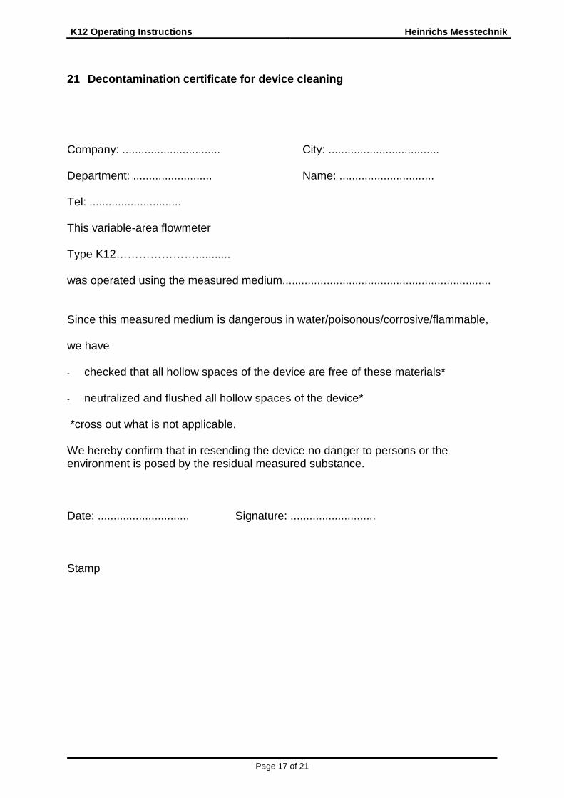
21 Decontamination certificate for device cleaning Company: ............................... City: ................................... Department: ......................... Name: .............................. Tel: ............................. This variable-area flowmeter Type K12…………………........... was operated using the measured medium.................................................................. Since this measured medium is dangerous in water/poisonous/corrosive/flammable, we have - checked that all hollow spaces of the device are free of these materials* - neutralized and flushed all hollow spaces of the device* *cross out what is not applicable. We hereby confirm that in resending the device no danger to persons or the environment is posed by the residual measured substance. Date: ............................. Signature: ........................... Stamp

Heinrichs Messtechnik K12 Operating Instructions
Page 18 of 21
22 EC Type Examination Certificate of the limit tra nsducer
22.1 Manufacturer Pepperl & Fuchs Note: actual certificates see our homepage/download area K12
22.2 Manufacturer ifm electronic Note: actual certificates see our homepage/download area K12

K12 Operating Instructions Heinrichs Messtechnik
Page 19 of 21
23 Declaration of conformity
Konformitätserklärung Declaration of Conformity
No. 16.4132.01 Hersteller: Manufacturer:
Heinrichs Messtechnik GmbH Robert-Perthel-Strasse 9 50739 Köln
Produktbeschreibung: Product description:
Schwebekörper -Durchf lussmessgerät vom Typ K09 bis K32 Variable Area Flowmeter Model K09 to K32
Hiermit erklären wir, in alleinige Verantwortung, dass das oben genannte Messsystem den Anforde-rungen der folgenden EU-Richtlinien, einschließlich allen bis heute veröffentlichten Änderungen bzw. Nachträgen entspricht: We declare herewith, in sole responsibility, that the product described above is conform with the provi-sions of the following EU-directives, including all published changes and amendments as of today: 2014/30/EU (EMC) (nur für Geräte mit Sensor)
EU-Richtlinie über die Elektromagnetische Verträglichkeit EU-Directive relating to electromagnetic compatibility
2014/34/EU (ATEX) EU-Richtlinie über Geräte zur Bestimmungsgemäße Verwendung in explosi-onsgefährdeten Bereichen. EU-Directive relating to electrical equipment intended for use in potentially explosive atmospheres
Anhang N und X sind ein integraler Bestandteil dieser Erklärung Annex N and X are an integral part of this declaration Köln, den 02.09.2016
Frank Schramm (Geschäftsführung / General Manager)
Kontakt : Tel: +49 (221) 49708-0 Contact: Email: [email protected] Web: www.heinrichs.eu

Heinrichs Messtechnik K12 Operating Instructions
Page 20 of 21
Anhang N zur Konformitätserklärung Annex N of the Declaration of Conformity
No. 16.4132.01
Produktbeschreibung: Product description:
Schwebekörper -Durchflussmessgerät vom Typ K09 bis K32 Variable Area Flowmeter Model K09 to K32
Die Konformität mit den auf Seite 1 genannten Richtlinien diese Erklärung wird nachgewiesen durch die Einhaltung folgenden Normen (gegebenenfalls abhängig von Gerätvariante): Conformity to the Directives referred to on Page 1 of this Declaration is assured through the applica-tion of the following standards (possibly dependent on version of device): X: Zutreffende Norm / Applicable Standard
Name und Anschrift der Benannte Stelle / Name and Address of the Notified Body TÜV-SÜD-Industrie Service GmbH TÜV SÜD Gruppe Westendstraße 193 D-80686 München
DEKRA EXAM GmbH Carl-Beyling-Haus Dinnendahlstraße 9 D-44809 Bochum ID-Nr. / ID-No.: RL 2014/34/EU: 0158
Richtlinie Directive
Norm –Ref. Nr. Standard / Ref. No. DIN EN -
Ausgabe Edition
Norm Beschreibung Standard Description
K09
K12
K17
K32
Anb
au e
lekt
risch
e S
enso
r A
dd-o
n el
ectr
ical
sen
sors
A
dd
2014/30/EU
61000-6-2 2011-06 Immunity Industrial environment X
61000-6-3 2012-11 Emission residential environment X
55011 2011-04 Radio frequency disturbance X
61326-1 2011-07 EMC requirements X
2014/34/EU
60079-0 2012+A11 General requirements X
60079-11 2012 Intrinsic Safety „i“ X
1127-1 2008-2 Grundlagen und Methodik X X X X
13463-1 2009-07 General requirements non elec-
trical devices X X X X
K12 Operating Instructions Heinrichs Messtechnik
Page 21 of 21
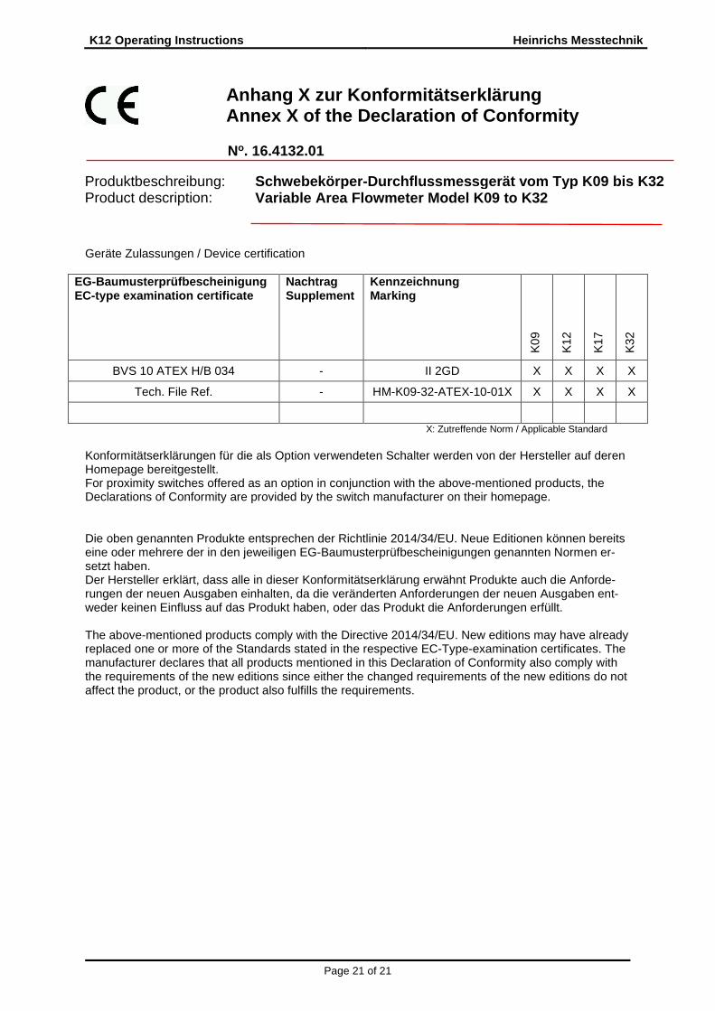
Anhang X zur Konformitätserklärung Annex X of the Declaration of Conformity
No. 16.4132.01
Produktbeschreibung: Product description:
Schwebekörper -Durchflussmess gerät vom Typ K09 bis K32 Variable Area Flowmeter Model K09 to K32
Geräte Zulassungen / Device certification
EG-Baumusterprüfbescheinigung EC-type examination certificate
Nachtrag Supplement
Kennzeichnung Marking
K09
K12
K17
K32
BVS 10 ATEX H/B 034 - II 2GD X X X X
Tech. File Ref. - HM-K09-32-ATEX-10-01X X X X X
X: Zutreffende Norm / Applicable Standard Konformitätserklärungen für die als Option verwendeten Schalter werden von der Hersteller auf deren Homepage bereitgestellt. For proximity switches offered as an option in conjunction with the above-mentioned products, the Declarations of Conformity are provided by the switch manufacturer on their homepage. Die oben genannten Produkte entsprechen der Richtlinie 2014/34/EU. Neue Editionen können bereits eine oder mehrere der in den jeweiligen EG-Baumusterprüfbescheinigungen genannten Normen er-setzt haben. Der Hersteller erklärt, dass alle in dieser Konformitätserklärung erwähnt Produkte auch die Anforde-rungen der neuen Ausgaben einhalten, da die veränderten Anforderungen der neuen Ausgaben ent-weder keinen Einfluss auf das Produkt haben, oder das Produkt die Anforderungen erfüllt. The above-mentioned products comply with the Directive 2014/34/EU. New editions may have already replaced one or more of the Standards stated in the respective EC-Type-examination certificates. The manufacturer declares that all products mentioned in this Declaration of Conformity also comply with the requirements of the new editions since either the changed requirements of the new editions do not affect the product, or the product also fulfills the requirements.