variable length wind turbine blade
TRANSCRIPT

DE-FG36-03GO13171 Energy Unlimited, Inc.
Page 1 of 47
Variable Length Wind Turbine Blade
Final Report , May 30, 2006 Award Number: DE-FG36-03GO13171

DE-FG36-03GO13171 Energy Unlimited, Inc.
Page 2 of 47
Project Title: Variable Length Wind Turbine Blade Covering Period: Entire Project, October 1, 2003 to March 31, 2005 Date of Report: May 30, 2006 Recipient: Energy Unlimited, Inc. Award Number: DE-FG36-03GO13171 Working Partners: Dynamic Design Engineering, Inc., Knight and Carver Wind Blade Division Cost-Sharing Partners: Dynamic Design Engineering, Inc., Knight and Carver Wind Blade Division Contact: Mark H. Dawson Energy Unlimited, Inc. 6600 Roe St. Boise, ID 83703 208 853-6291 Project Team: DOE HQ Program Manager Lisa Barnet
DOE Field Project Officer Gibson Asuquo Project Officer/Manager, Deborah Weems Contract Specialist/Officer, Michael Schledorn Project Monitor, Marcus Farmer

DE-FG36-03GO13171 Energy Unlimited, Inc.
Page 3 of 47
TABLE OF CONTENTS
Page Table of Pictures 4 Table of Tables and Graphs 5 1. Project Objective . . . . . . . 6 2. Summary 6 3. Background 6 4. Patents 6 5. Publications / Presentations 6 6. Project Narrative 7 7. Task Schedule 8 8. Technical Results . . . . . . . 11
8.1 Aerostar 9 Meter Blade Inspection 11 8.2 Blade Root mold 13 8.3 Blade Layup 15 8.4 Tip Mold 17 8.5 Slides and Supports 19 8.6 Drive Train 20 8.7 Controller 20 8.8 Fabrication 24 8.9 Static Testing 27 8.10 Power Curve Testing 29 8.11 Results . . . . . . . 34
8.11.1 Static Tests 34 8.11.2 Site Calibration 36 8.11.3 Power Curves 38 8.11.4 Vocabulary 43 8.11.5 Benefits of Variable Length Blades 45
9. Conclusions and Next Steps 46

DE-FG36-03GO13171 Energy Unlimited, Inc.
Page 4 of 47
TABLE OF P ICTURES
Page Cover Variblade Flying in San Gorgonio near Standard Blades 1 Picture 1 Original Proof of Concept Variblade 12 Picture 2 Variblade Root Mold 13 Picture 3 Root End of Variblade Root Mold 14 Picture 4 Laying up a Root Blade Skin 15 Pictue 5 A Finished Root Blade Skin 16 Picture 6 Plug and Molds for Variblade Tip 17 Picture 7 Skins Laid Up in Variblade Tip Molds 18 Picture 8 Fitting Spars and Bulkhead into Root Blade 19 Picture 9 Drive Train Mounted on Bulkhead 20 Picture 10 Up Tower Control Box Wiring 21 Picture 11 Blades Wired and Ready for Automatic Operation 22 Picture 12 Wiring Controller on Hub 23 Picture 13 Jig for Transferring Tip Chord to Root Using Smart Level 24 Picture 14 Fitting Tip into Root 25 Picture 15 It Fits! 25 Picture 16 Root Studs Aligned and Ready for Bonding into Root 26 Picture 17 Tip Tip Construction 26 Picture 18 Tip Static Load Test 27 Picture 19 Static Testing Completed Blade 28 Picture 20 Test Site, Turbine C34 and Anemometer Tower 29 Picture 21 Anemometer Booms on Test Turbine 30 Picture 22 Test Blades in Long Position, next to Standard 9 Meter Blades 31 Picture 23 Blades Short Position 31 Picture 24 Extended Blades and Manbasket 32 Picture 25 Flight crew on first day of testing 33

DE-FG36-03GO13171 Energy Unlimited, Inc.
Page 5 of 47
TABLE OF T ABLES and GRAPHS
Page Table 1 Task Schedule 9 Table 2 Variblade Static load Test Results 12/2/04 35 Table 3 Variblade Flapwise Frequency at Various Lengths 35 Table 4 Minutes of Wind Speed Data 36 Table 5 Site Calibration Report 37 Graph 1 Tip Deflection v.s. Pounds 34 Graph 2 Proof of Concept Variblade Power Curve 38 Graph 3 Variblade Power Curve 39 Graph 4 When Power is Produced 40 Graph 5 10 Minute Average Power Production 41 Graph 6 Peak Power Occurrences 42

DE-FG36-03GO13171 Energy Unlimited, Inc.
Page 6 of 47
1. Project Objective. The purpose of the project is to advance this technology from an inefficient, proof of concept prototype to a working prototype which can be used to estimate manufacturing costs and annual energy production of variable length wind turbine blades (Variblades). A commercial blade of variable length should increase annual power production while reducing peak mechanical loads on wind turbines. This will help lower the cost of wind power, making wind power a more viable method of generating electricity. 2. Summary. This variable length wind turbine blade project met the project objectives by successfully completing the task schedule. A set of variable length blades (8 to 12 meters in length) is now flying, in a configuration that is representative of a commercial blade designed to replace a standard 9 meter blade. Static testing and operations show that the blades are stiff enough to prevent tower strikes. Power curve testing shows significant gains in low wind speed power production. An improved controller and drive mechanism have now been working for 18 months. The project increases knowledge of construction methods and blade performance, as well as production costs of variable length wind turbine blades. The net result is to help reduce the cost of wind energy by increasing annual power production without overloading wind turbines. Moving forward, we continue to monitor power curve, controller performance, and blade integrity. The project has made good progress towards understanding the costs and challenges associated with commercial production of variable length blades. Items that will require further study are: tip airfoil; tip and root interface design; jigs for more efficient construction, and optimization of subsystems. 3. Background. The Variable length turbine blade was first conceptualized in 1997 as a result of inspecting lightweight Kenetech 56-100 blades and comparing them to our heavy Aerostar 9 meter blades. We decided to combine the two designs, and in 2002 we started flying the first variable length wind turbine blades on a Bonus 120 kW turbine. These blades were made out of Kenetech 56-100 tips mounted to slides on Aerostar 9 meter blades. That effort was our proof of concept blade. However, it did not provide an efficient blade, because the tip did not fit within the root blade. The blade did change in length from 8 meters to 11 meters, and showed promising power curves. A controller was developed to change the blade length in response to turbine output while the turbine was flying. This proof of concept design used winches to move the blades. The proof of concept blades flew for 34 months, until they were replaced by the proof of manufacture blades made during this project. The basic concept of variable length blades is to increase the swept area of the rotor when there are low winds. As winds increase, the rating of the turbine will be achieved, and as the wind continues to increase, the blades are retracted. This retraction of blades reduces the swept area of the rotor, which lowers loads on the turbine, and maintains a pre-determined turbine output. In stormy conditions, the blades can be run

DE-FG36-03GO13171 Energy Unlimited, Inc.
Page 7 of 47
shorter than the standard length blades they replace. The ability to run larger blades in low winds is the equivalent to adding sails to a sailboat. The net result is more annual production because there are many hours in a year when winds are below the 25 to 30 mph that is required to produce full power from a wind turbine. Inspection of a typical wind speed distribution shows that there are about 6,000 hours per year when it is beneficial to have longer blades on wind turbines. However, one cannot simply install longer fixed length blades because the turbine would then be damaged during high wind periods. 4. Patents. No patents are being sought as a result of this award. Previous to this award, in June 2003, a patent for the Variable length wind turbine blade was applied for. That patent, #6,902,370 B2 was published June 7, 2005. 5. Publications / Presentations. The Variblade concept was presented at a booth at the 2003, 2004 and 2005 American Wind Energy Association (AWEA) conventions. A presentation to IEEE was made in San Francisco on June 23, 2005 reporting preliminary results of this project. Presentations were also made at the November, 2005 18th NREL Industry Growth Forum in San Francisco, and the 2005 California Wind Energy Collaborative Forum. 6. Project Narrative. Cutting open an existing blade showed how difficult it would be to retrofit existing blades. Since molds no longer exist for these blades, the project scope was modified to include constructing a mold so that new root blades could be produced. The mold was made using an existing 9 meter Aerostar blade as a plug. An existing tip mold was used because it was designed to make a tip that will fit inside an Aerostar 9 meter blade. The blade work was performed at Knight and Carver�s facility in San Diego, California. It was noted that the molds and blade skins were easily fabricated by their experienced blade staff. However, the task of designing and fitting the drive train, slides, spars, limit switches, etc. proved to be more time consuming than anticipated. The blades were completed and installed in December, 2004. The turbine was shut down to measure wind speeds to get a correlation between the turbine and the nearby met tower. Once the correlation was complete, the turbine began to run in test mode. Since the variable length wind turbine blade is a new device, a vocabulary list was developed to allow everyone to communicate clearly. The list is alphabetical, and covers nomenclature of the drive train, attachment mechanisms, controller, and the blades. This list is shown in section 8.11.4. As we worked through the challenges of building parts for the first time, we became much more aware of the importance of creating interchangeable parts. In order for the project to achieve economical production rates and reliable performance, the

DE-FG36-03GO13171 Energy Unlimited, Inc.
Page 8 of 47
manufacturing process will have to be moved from hand fitting to more of a mass production technique. The project led to a better understanding of the tasks that need to be followed in order to come closer to commercial production. Preliminary power curves are showing the long position of the variable length blades is out producing standard 9 meter blades in low winds. During a five month period, from September, 2005 through January, 2006, the Variblade equipped test turbine out produced the standard bladed turbine next to it by 11%. The instantaneous peak outputs of the varibladed turbine were lower and less frequent than the standard turbine, with 1/3 as many peaks at 160, 170 and 180 kW, and no peaks above 190 kW, while the standard turbine did peak above 190 kW. See section 8 for more detailed production information. The blades produced in this project weighed about just over 1,200 lbs, compared to the Aerostar 9 meter blade, which weighs about1500 lbs. This weight includes the drive mechanism, which is located near the root end of the blade. As shown in the following task schedule, the project consisted of 19 tasks, which have been successfully completed. The root molds are complete, and three complete variable length blades have been constructed. The blades were static tested, and mounted on a Bonus 120 turbine in December, 2004. They are currently running in various positions depending on wind speeds as power curve testing continues. 7. Task Schedule. The following table shows the task Schedule, with completion dates and progress notes.

DE-FG36-03GO13171 Energy Unlimited, Inc.
Page 9 of 47
Table 1. Task Schedule
Page 1
Task Completion Date Task
# Task Description Original Planned
Revised Planned Actual
%
Complete
Progress Notes
1 Kickoff meeting 10/20/03 10/21/03 100
All participants met for two days at Knight and Carver�s facility in San Diego for a tour of the facilities, and an overview of the project. A list of to-do items was produced, and the project was officially on its way.
2 Review of Prototype 12/1/03 12/31/03 100
The workers at the fiberglass plant have received the forms for the tip section. Dynamic Design has received drawings and a section of the tip mold, as well as documentation and pictures of the existing prototype. This information has been reviewed, and is being incorporated into the ongoing design process.
3
Blade aerodynamic design 12/31/03 2/15/04 3/30/05 100
The Aerodynamic design on this project will focus on the transition between the root and the tip sections. Drag at this location will become more critical as the variable length concept is applied to longer blades. The blades are currently running and data analysis will attempt to quantify blade drag at the transition
4 Blade Structural Design 1/15/04 6/15/04 7/30/04 100
Structural design is focused on the following tasks: Root design and bolt inserts for the root section of the blade; lay up schedule for the root section: spar and tip slide design; lay up schedule for the tip section; drive attachment points on the root and tip, spar design for the tip. All of these tasks are complete including root winding techniques and access plates.
5 Actuator Design 1/15/04 4/15/04 100
The actuator mechanism is a screw drive. The screw, drive motor, gear reducer and mounting mechanisms have been sized and all components have been received. Motor mounts and bearing sleeves have been manufactured.
6 Procure Turbine, Blades 2/1/04 2/15/04 100
The test turbine is ready for use. As of 2/15/04it was still fitted with the proof of concept blades. Three 9 meter blades have been delivered to Knight and Carver
7 Cut Blades and inspect 3/15/04 10/23/03 100
One 9 meter blade has been completely dissected. This showed that these old blades have a lot of variation in glue line thickness (up to ¾ inch). Field experience shows these blades varying in weight by as much as 300 lbs in an 1800 lb lbade design. This blade was used to reverse engineer the fabric lay up schedule for the new root sections.

DE-FG36-03GO13171 Energy Unlimited, Inc.
Page 10 of 47
Table 1. Task Schedule (continued)
Page 2
Task Completion Date Task
# Task Description Original Planned
Revised Planned Actual %
CompleteProgress Notes
8 Build Blade Tools 4/15/04 6/15/04 6/15/04 100
Tip and root molds are complete. Root winding and drilling jigs are complete and tested. The tip construction has shown that additional construction jigs and fixtures will have to be made to guarantee consistent, foolproof construction during manufacture.
9 Build blade parts 5/15/04 7/15/04 8/15/04 100
All parts have been constructed for the blades, including the transition piece between the root and tip
10 Modify and assemble root 6/1/04 8/15/04 8/15/04 100
Root blades have been built new, rather than modifying old blades. Three roots have been fitted with drive and slide parts. All three blades have been built up, drilled out, and have had root studs inserted.
11 Procure actuator mechanism 6/1/04 6/15/04 6/15/04 100
All parts have been ordered, received and installed in the blades. They have been run in and out and limit switches are installed to control motion.
12 Procure controller 6/1/04 11/31/04 11/31/04 100 The controller is complete and undergoing testing.
13 Blade Assembly 7/1/04 8/30/04 11/15/04 100
All three blades have been fitted with spars, slides and a bulkhead to accept the drive motor. Drive assemblies are installed and operational. Tips have the drive nuts installed. Cutouts have been made for limit switches and maintenance, and all limit switches have been installed. The tip support mechanism is installed and roots are complete. The blades are currently running on a Bonus 120 turbine.
14 Blade Installation 7/15/04 11/30/04 12/10/04 100 Blades were installed on a Bonus 120 turbine on December 10, 2004.
15 Testing Setup 8/1/04 1/30/04 100
We have installed a test stand. The static testing is complete. All instrumentation is installed and operating
16 Testing 11/30/04 3/15/05 3/30/05 100
The blades are fabricated, and have undergone physical testing to verify proper motion and control. Static load tests are complete, and the blades are installed and undergoing power curve testing.
17 Analysis 12/31/04 3/15/05 6/30/05 100 Control system analysis is complete. Power curve and static test analyses are complete.
18 Quarterly Reports 3/31/05 100
This project will have 6 quarterly reports. The final report documents completion of section 17, Analysis, and section 19 final report.
19 Final Report 3/31/05 6/30/05 100 Final report submitted.

DE-FG36-03GO13171 Energy Unlimited, Inc.
Page 11 of 47
8. Technical Results. The scope of this project was broad for the amount of funding. Therefore, some items were completed with minimal engineering study in order to preserve funds for actual construction and operational testing. This approach allowed a new generation of blade to be produced so that multiple lessons can be learned from an actual flying model. Even though that model will undoubtedly be refined, it will allow us to study dynamic loading, life cycles of moving parts, controller operations, production costs, and real life turbine power production. 8.1 Aerostar 9 Meter Blade Inspection. The first technical task was an inspection of an existing 9 meter blade to determine the best way to retrofit it for variable length operation. Efforts to open the blade showed an extremely robust and heavy construction. The I-beam spars were glued to the structural skins with liberal amounts of concrete-like glue, filling large gaps up to ¾ inch thick. The blade skin was destroyed while opening the blade. Spar location was noted to be within the area that would be occupied by the movable tip. This meant that the spars would have to be removed to allow the construction of a movable tip, whose slide supports would become new spars with larger spacing between them. This type of retrofit would introduce two types of structural weak points in the original blade:
1. A discontinuity where the old and new spars were connected, since they would not line up with each other.
2. The original skins were a structural part of the blade only between the original spars. This means that the skins only contained unidirectional fibers on top of and between the spars. The leading and trailing edges of the blades are not structural. The strong portion of the original skins would not tie in with the new spars, which would have to be further apart.
Both of these problems, and the difficulty in opening the blade without damaging the skins, meant that a simple blade retrofit would entail significant redesign and construction on the old blade. Since the old blades were not uniform in weight or dimensions, it was determined that it would be quicker and easier to build new blades rather than retrofitting existing blades. The decision to build new root blades also avoided the problem of reusing failing root sections on the original Aerostar blades, which have all seen many years of service. Here is a view of the end of an Aerostar 9 meter blade being used on the original proof of concept blade. Note the liberal use of glue, and the thickness of the skins.

DE-FG36-03GO13171 Energy Unlimited, Inc.
Page 12 of 47
Picture 1. Original Proof of Concept Variblade
DE-FG36-03GO13171 Energy Unlimited, Inc.
Page 13 of 47
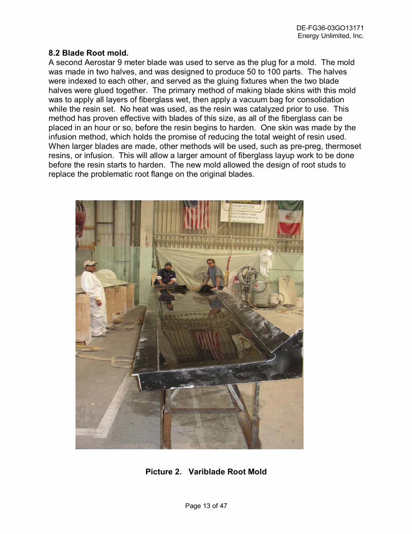
8.2 Blade Root mold. A second Aerostar 9 meter blade was used to serve as the plug for a mold. The mold was made in two halves, and was designed to produce 50 to 100 parts. The halves were indexed to each other, and served as the gluing fixtures when the two blade halves were glued together. The primary method of making blade skins with this mold was to apply all layers of fiberglass wet, then apply a vacuum bag for consolidation while the resin set. No heat was used, as the resin was catalyzed prior to use. This method has proven effective with blades of this size, as all of the fiberglass can be placed in an hour or so, before the resin begins to harden. One skin was made by the infusion method, which holds the promise of reducing the total weight of resin used. When larger blades are made, other methods will be used, such as pre-preg, thermoset resins, or infusion. This will allow a larger amount of fiberglass layup work to be done before the resin starts to harden. The new mold allowed the design of root studs to replace the problematic root flange on the original blades.
Picture 2. Variblade Root Mold

DE-FG36-03GO13171 Energy Unlimited, Inc.
Page 14 of 47
Picture 3. Root End of Variblade Root Mold

DE-FG36-03GO13171 Energy Unlimited, Inc.
Page 15 of 47
8.3 Blade Layup. Since the final production model of this blade may well employ a different blade profile, minimal effort was put into optimizing the fabric schedule. The original Aerostar blade was sectioned and measured to determine the layers of fiberglass used at various blade locations. This amount was used in the new blade, while making sure that the unidirectional fabric was wide enough to carry loads to the spars. The Aerostar blades have proven to be durable for more than 15 years, so a copy of their layup schedule was deemed appropriate for this project. Better construction techniques, control of glue lines to 1/8�, and the elimination of some mat produced a blade that weighs less than the Aerostar. The entire 8 � 12 meter Variblade, including the drive train, weighs about 300 pounds less than the original 1500 pound 9 meter Aerostar blade.
Picture 4. Laying up a Root Blade Skin

DE-FG36-03GO13171 Energy Unlimited, Inc.
Page 16 of 47
Pictue 5. A Finished Root Blade Skin

DE-FG36-03GO13171 Energy Unlimited, Inc.
Page 17 of 47
8.4 Tip Mold. Due to monetary constraints, an existing mold was used to make the movable tip section of the blade. This mold was based on a NACA 63.xx profile in order to make tips that would fit within the original Aerostar blades. In the future, both the root and tip blade profiles will be optimized for physical compatibility and power production. The goals of this project were better met with the use of this existing mold because we were then able to put more resources into producing an operational set of blades. These molds did not have good hinges or alignment pins for use as gluing jigs. Therefore, the tip cross section had some variation along the length of the blade., This caused some minor fitting problems as the blades were put together. This pointed out the importance of having good jigs and molds so that all parts will be interchangeable in a manufacturing situation.
Picture 6. Plug and Molds for Variblade Tip

DE-FG36-03GO13171 Energy Unlimited, Inc.
Page 18 of 47
Picture 7. Skins Laid Up in Variblade Tip Molds

DE-FG36-03GO13171 Energy Unlimited, Inc.
Page 19 of 47
8.5 Slides and Supports. In order to insert the tip into the root blade, a set of slides, spars and drive mechanism supports had to be fabricated. A challenge with the spars was to allow the blade to remain structurally strong while allowing enough room between the spars to fit the tip. Additionally, the spars had to remain parallel and at a fixed distance from each other over their entire length. The spars were fabricated individually, and glued to the bottom blade skin while held at the proper attitude with wood fixtures. Another challenge was to hold the spars in alignment within the tapered and twisted root. This process will actually become easier with bigger blades, as most of the twist occurs in the inboard portion of the blade, while the movable tip will occupy the straighter outboard end of the blade. The main conclusion made during this process was that significant work remains to be done in making jigs that will allow simple construction that results in interchangeable parts and minimal fabrication costs.
Picture 8. Fitting Spars and Bulkhead into Root Blade

DE-FG36-03GO13171 Energy Unlimited, Inc.
Page 20 of 47
8.6 Drive Train. A screw drive was designed to fit within the root blade and the tip blades. Design constraints were: access for maintenance; simple, off the shelf components; meeting design loads; lubrication; and use of a DC motor for reliable operations during power outages. Other details include provision of a bulkhead for drive train mounting; position indication, and cutouts for limit switches. Access to the drive is provided with a cover on the shark fin portion of the blade. The drive frame, motor, coupling, screw and bearing weigh about 200 lbs. The drive train is capable of moving the blade in and out with the turbine running, and it is capable of doing so without AC power available. The Bonus 120 brakes are capable of stopping fully extended blades upon loss of power. For commercial deployment, redundant braking systems will be required.
Picture 9. Drive Train Mounted on Bulkhead 8.7 Controller. The controller is an improvement on the original proof of concept controller. It tracks the position of each blade and keeps the blade lengths equal by counting flags on the screw drive. If individual blade counts vary more than an adjustable setpoint, an alarm occurs. Controls include a slip ring to carry power and signals between the hub and the tower. The blade controller, batteries, and charger are

DE-FG36-03GO13171 Energy Unlimited, Inc.
Page 21 of 47
all mounted on the hub. This is a system that will be easier to deploy on larger turbines because there is more room in the hub. Blade length is varied in response to turbine power output, as measured at the turbine controller. Variable setpoints allow the blade action to be tailored to a specific turbine or wind regime. The turbine can be set to run at any specific power output, so the operator has the ability to choose how hard he wants to run the turbine. The controller and drive train can move the blades at any time, dynamically adjusting blade length as the turbine runs. One method of optimizing the controller might be using radio signals instead of hard wiring for transferring data between the blades, hub, and the tower controller. At this time, the controller consists of two programmable logic controllers (PLC�s). One is in the hub, and the other is at the base of the tower. This provides an economical control system, which can be programmed to vary performance. Currently it is set to watch generator kW, with a high and low setpoint separated by a dead band. The intent is to limit blade hunting by leaving the length fixed whenever the turbine output falls within the deadband. Timing circuits allow for rapid response to winds exceeding the upper setpoint. The response to falling production is dampened to prevent hunting. The control philosophy is to provide a simple, inexpensive method of responding to power fluctuations. The controller can accept other inputs such as wind speed, vibration, accelerometer, or load cell outputs. At this time, generator kW is considered to be a good indicator of system loads which might be indicated by those alternative inputs. There are two types of alarms generated by the controller. Emergency alarms trip the turbine controller, shutting down the turbine. Minor alarms are annunciated, and may halt the motion of the blade tip, but do not stop the turbine. This allows the turbine to continue making power, even though the variable length blade may be having minor problems. For instance, during stormy weather, a non functional variable length blade can be left in its short position, and the turbine can continue to produce power without risk.
Picture 10. Up Tower Control Box Wiring

DE-FG36-03GO13171 Energy Unlimited, Inc.
Page 22 of 47
Picture 11. Blades Wired and Ready for Automatic Operation
Access plates in nosecone cover battery chargers.

DE-FG36-03GO13171 Energy Unlimited, Inc.
Page 23 of 47
Picture 12. Wiring Controller on Hub
Note one of three batteries and relay boxes mounted under the nose cone.

DE-FG36-03GO13171 Energy Unlimited, Inc.
Page 24 of 47
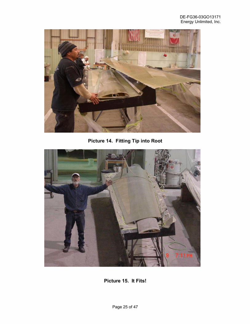
8.8 Fabrication. Fabrication of the root skins and tips was done quickly and easily by the experienced blade crew at Knight and Carver. Skins were laid up wet, vacuum bagged, and cured on a schedule of about 1 skin per mold per day. Since there are molds for both the top and bottom skins of the tip and root, production of skins for a blade per day was achieved. The design and fitting of the spars, drive train, slides, tip support, limit switch mounts, root winding, bolt insert drilling and gluing, and transition to the tip were all much slower, as they had never been done before. One blade skin was produced using the infusion process. This resulted in a lighter skin due to the more efficient use of resin. During manufacture, savings are achieved by reducing resin use. However, this process involves a learning curve to establish efficient edge sealing and injection points. Therefore, it is not necessarily a better alternative to the more familiar wet layup. As blades become larger, the use of prepreg and thermoset resins allow longer working time for fabric layout. However, as the variable length blades are applied to larger turbines, the movable tip components are not necessarily so large that new methods would be required. Consider the fact that a minimal target for variable length blades would be to replace the use of three standard blade lengths on a 1.5 MW turbine. This class of turbines typically uses blades between 65 and 80 meters in diameter. A variable tip would need to change 7.5 meters to cover this range. With a slide section two meters long, this is only a 9.5 meter tip, which does not trigger any new methodology for layup.
Picture 13. Jig for Transferring Tip Chord to Root Using Smart Level
DE-FG36-03GO13171 Energy Unlimited, Inc.
Page 25 of 47
Picture 14. Fitting Tip into Root
Picture 15. It Fits!
DE-FG36-03GO13171 Energy Unlimited, Inc.
Page 26 of 47
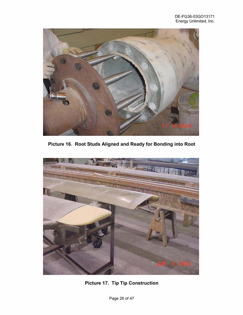
Picture 16. Root Studs Aligned and Ready for Bonding into Root
Picture 17. Tip Tip Construction

DE-FG36-03GO13171 Energy Unlimited, Inc.
Page 27 of 47
8.9 Static Testing. Static testing was performed on one tip section and one variable length blade at long, medium and short positions. The static tests were designed to verify that the blades could handle expected loads without excessive deflection or failure. Of special concern was the total deflection of the extended blade. This is because the Bonus 120 turbine has a man basket located part way up the tower, 72 inches horizontally from the blade. When the blade is at full length, it extends well below this basket, and excessive deflection could cause a blade strike. The static tests showed that under full load conditions, the deflection was less than half of that needed to produce a blade strike on the man basket. . Procedures: 1. The tip section was tested by placing its root end on a concrete block and weighting
it to prevent tipping. The tip was mounted with the lifting side down, so weights would simulate blade lift forces. The cantilevered tip was then loaded and deflections were measured. This test did not verify the strength of the edges of the root, where slides transfer loads to the root blade. However, those were tested in the following procedure.
Picture 18. Tip Static Load Test

DE-FG36-03GO13171 Energy Unlimited, Inc.
Page 28 of 47
2. The assembled blade was weighed to determine how much its own weight would contribute to the static loads. The weight of the tip end of the extended blade was recorded while the root remained on the ground. The blade was then mounted on a test fixture which held the blade by its root bolts. The blade extended horizontally, full length with the lifting face down. The blade was then lifted at the tip by its own weight to establish the zero load position as a distance from the ground. Successive weights were then added to the blade, and deflections were measured. Additionally, the blade was bounced and its natural frequency was recorded at long, medium and short lengths. The test load was left on the blade as its length was changed to verify that the drive train was capable of functioning properly under load.
Picture 19. Static Testing Completed Blade
Note that the ground slopes away under the blade, so measurements to the ground vary with length from the root.

DE-FG36-03GO13171 Energy Unlimited, Inc.
Page 29 of 47
8.10 Power Curve Testing. The test turbine is located approximately 150 feet north of a 100 foot meteorological tower. The wind is primarily from the west, so the first task was to correlate the wind speeds at the turbine with those at the met tower. The site is too steep to place a met tower in front of the turbine. Calibrated anemometers were placed at the rotor base, hub and tip heights on the met tower. The turbine was mounted with two anemometers on booms. One was at hub height and extended 15 feet behind the turbine. The second extended 15 feet above the turbine. The turbine was taken off line and yawed out of the wind to prevent shading of the anemometers. Wind speed readings were taken until adequate numbers of samples were taken at each wind speed and direction. The actual number of minutes of data recorded in each direction are shown in Table 4. Since about 93% of the annual wind power comes from the west in San Gorgonio where the test turbine is located, it was decided to concentrate on understanding the wind speed correlation in the 280 to 315 degree directions, where most power is generated. Subsequent testing would not count wind data from other directions. The data was analyzed to produce a correlation between the turbine and the met tower for various wind speeds and directions. Raw direction data was adjusted 30 degrees to correct the mounting angle of the wind vane, which was referenced to 330 degrees due to its mounting position on the triangular met tower.
Picture 20. Test Site, Turbine C34 and Anemometer Tower

DE-FG36-03GO13171 Energy Unlimited, Inc.
Page 30 of 47
Picture 21. Anemometer Booms on Test Turbine
The second task was to gather power output data from the operating turbine while measuring wind speeds, direction, temperature, pressure, and blade length. The turbine was run with the blades in three basic positions: long; medium, and short. The data was analyzed to produce power curves for the three blade lengths. These power curves are used to compare the variable length blade�s theoretical power production to that of a standard 9 meter blade. The comparisons are made for a wind regime typical in San Gorgonio, California, and Idaho. This shows the sensitivity of using a variable length blade in different wind regimes. Continuing monitoring will produce a composite power curve that accurately portrays the actual performance of the blade and controller. Changes in controller behavior will modify the actual power curve because the blade will not always be in the theoretical optimum position. That analysis is ongoing, and will be the subject of future work.

DE-FG36-03GO13171 Energy Unlimited, Inc.
Page 31 of 47
Picture 22. Test Blades in Long Position, next to Standard 9 Meter Blades
Picture 23. Blades Short Position

DE-FG36-03GO13171 Energy Unlimited, Inc.
Page 32 of 47
Picture 24. Extended Blades and Manbasket
Note how the variable length blade extends well below the man basket as opposed to the standard 9 meter blade in the foreground. The variable length blade is approximately 11 feet longer than the standard blade when extended, and 3 feet shorter when retracted.

DE-FG36-03GO13171 Energy Unlimited, Inc.
Page 33 of 47
Picture 25. Flight crew on first day of testing
from left to right: Inventors, Jack Wallace and Mark Dawson, EUI Consultant, Kevin Jackson, Dynamic Design Installer, Dave Copher, EUI Interested Observer, Brian Smith, NREL Gary Kanaby, Knight and Carver David Lamm, President, EUI

DE-FG36-03GO13171 Energy Unlimited, Inc.
Page 34 of 47
8.11 Results. 8.11.1 Static Tests The tip testing showed that the tip was able to withstand over 450 pounds applied near the tip, with a total deflection of 26�. This indicates that the amount of glass and its orientation are acceptable as a first approximation to withstand estimated loads while limiting deflection to a value that will not cause blade strikes.
Graph 1. Tip Deflection v.s. Pounds
When the tip was incorporated into the root blade, the following was observed: 1. Fully extended blade lifted by tip of root section while root remained on ground: Weight = 625 lbs 2. Noted sag of tip under its own weight (80 lb at tip) in fully extended position = 5 in. 3. Loaded the blade into the test stand and determined its unloaded blade tip position above the ground reference plane by lifting up 625 pounds at the tip of the root section, measuring distance to the ground, and adding another 5 inches for the sag of the tip under its own weight. Root tip height = 5� 1� Tip tip height = 10� 4� Note that the ground slopes under the test stand, so there are larger measurements at the tip of the blade. See picture 19.

DE-FG36-03GO13171 Energy Unlimited, Inc.
Page 35 of 47
4. We determined that a poof load should be in the range of 32.435 lb-ft moment at the root, based on 100 mph wind stagnation loads (25.6 lb/square foot) acting on the centroid of the area of the blade (78 square feet, 16.25 feet from the root). Acknowledging that the blade weight represented a portion of the test load of 625 pounds acting at the tip of the root blade (8.33 m from the root), we determined that an additional weight of about 500 lbs was needed, if applied half way out the extended tip (9.22 m from the root).
The horizontal distance from the blade to the man basket was measured at 72 inches. Based on this distance, the total deflection of 29 inches observed under static testing is deemed to be safe. There is no danger of the blade striking the tower man basked under normal operating procedures, where turbine production is maintained at or below the turbine rating. As winds increase, the blades will be retracted, which reduces deflections. Ultimately, the blade is pulled above the man basket in its shorter positions, where it would have to bend another two feet to contact the tower. This is not possible, as the tip of the root is only deflecting a few inches under the test load.
Table 2. Variblade Static load Test Results 12/2/04
Deflections are for the fully extended blade, with loads placed as shown
Blade Elevations Blade Deflections Load Placement Root Tip Tip Tip Root Tip Tip Tip
Unloaded Blade 5' 1" 10' 4" Blade under Gravity Load 4' 11" 9' 6" 2" 10" 320 lb at 9.22 meters 4' 9" 8' 6" 4" 22" 490 lb at 9.22 meters 4' 8" 7' 11" 5" 29"
Note that the ground slopes away from the test fixture. This makes the tip tip measurements to the ground larger than those of the root tip.
5. The natural frequency of the blade was measured at long, intermediate and short positions.
Table 3. Variblade Flapwise Frequency at Various Lengths
POSITION LENGTH FREQUENCY (cycles/sec)
Long position 11.8 meters .664 Intermediate 9.22 meters .401 Short 8.33 meters .295

DE-FG36-03GO13171 Energy Unlimited, Inc.
Page 36 of 47
Since the rotational speed of the turbine = 45 rpm, the first per rev driving frequency is 45 cycles/60 seconds or .75 Hertz. This is higher than the first flapwise natural frequencies of the blade in the short, long or intermediate positions. Further testing will have to be performed to verify operating blade vibrations, both in-plane and out-of- plane. 8.11.2 Site Calibration The turbine anemometers showed excellent correlation to those mounted on the reference tower. The turbine mounted horizontal boom at hub height was generally less than one percent different in wind speed from either of the anemometers on the met tower. As expected, the vertical turbine boom showed slightly higher wind speeds than the reference tower because it extended above hub height. For the initial power curves presented in this report, the site calibration values have been assumed to be 1.00. As more in depth studies are carried out, these minor site calibration adjustments will be included in the power curves. Table 4 shows the number of minutes of wind speed data gathered in each speed bin. Note that the wind directions of interest are between 280 and 315 degrees. This is because 93% of the wind power in this location comes in this sector.
Table 4. Minutes of Wind Speed Data
Wind Direction in degrees
Minutes of data with wind speed > 4m/s
280- 285 280 285-290 270 290-295 320 295-300 560 300-305 1490 305-310 850 310-315 490 315-320 180
Table 5 shows the correlations between the turbine anemometers and the reference anemometer tower.

DE-FG36-03GO13171 Energy Unlimited, Inc.
Page 37 of 47
Table 5. Site Calibration Report
3/3/2005
EUI Section 31 WTG C-34 Desert Hot Springs, (Based only on data following the second yawing event)
mean wind sigma of mean Sensors Sector speed ratio wind speed ratio
horiz stinger / ws 1 267.5 0.9902 0.0037 horiz stinger / ws 1 372.5 0.9928 0.0037 horiz stinger / ws 1 377.5 1.0089 0.0036
horiz stinger / ws 2 267.5 0.9910 0.0037 horiz stinger / ws 2 372.5 0.9952 0.0037 horiz stinger / ws 2 377.5 1.0128 0.0036
vert stinger / ws 1 267.5 1.0031 0.0038 vert stinger / ws 1 372.5 1.0109 0.0038 vert stinger / ws 1 377.5 1.0360 0.0038
vert stinger / ws 2 267.5 1.0039 0.0038 vert stinger / ws 2 372.5 1.0133 0.0038 vert stinger / ws 2 377.5 1.0400 0.0038

DE-FG36-03GO13171 Energy Unlimited, Inc.
Page 38 of 47
8.11.3 Power Curves Power curves produced by the original proof of concept blades showed marked increases in power with blade length. Graph 1 shows the power produced by the proof of concept blades in short, medium and long positions.
Graph 2. Proof of Concept Variblade Power Curve
Note the power production exceeding 160 kW with the longer blades in higher winds in this chart for the original proof of concept blade. This data was taken with the proof of concept blades held at fixed lengths and zero degrees pitch. The next generation blades made for this project are also capable of reaching high power levels, but the first control algorithm used was designed to produce lower loads in high winds and higher production in low winds. Graph 3 shows the power output of the proof of manufacture blades, as well as the power curve of standard 9 meter Aerostar blades. Both curves were measured at the test site in San Gorgonio, and are adjusted to standard conditions. The data used for this graph is from a five month period starting in September, 2005, with the blades in automatic control. The variblades are pitched at positive 2 degrees, and the Aerostars are pitched at zero degrees. Note that there is a range of power output for each wind speed with the variblade, as opposed to a single point with standard blades. This is a result of the dead band and responsiveness of the current control algorithm, which was purposely made to be conservativeby reducing blade length quickly upon exceeding the upper set point, and delaying lengthening of the blades to reduce peak loads.

DE-FG36-03GO13171 Energy Unlimited, Inc.
Page 39 of 47
Graph 3. Variblade Power Curve Power Output in Automatic Control
Variblade vs. Standard 9m AerostarOn Bonus 120 in San Gorgonio
5 months data
0102030405060708090
100110120130140150
0 1 2 3 4 5 6 7 8 9 10 11 12 13 14 15 16 17 18 19 20 21 22 23
Wind speed (m/s)
Pow
er (k
W)
VaribladeStd 9 m
During this five month period, the variblade produced 12.9% more power than the standard 9 meter bladed turbine standing next to it, based on our regular meter readings used for revenue distribution. Note that the variblade consistently out-produces the 9 meter blade in low winds, and production is similar in high winds. The following three graphs show how the variblade performed over a 9 day period, while using the same conservative control algorithm used above.

DE-FG36-03GO13171 Energy Unlimited, Inc.
Page 40 of 47
Graph 4. When Power is Produced
Approximate kWh October 23 - November 1, 2005
0
500
1000
1500
2000
2500
3000
3500
010
's30
's50
's70
's90
's11
0's13
0's
kW bins
kWh Variblade
9 m Aerostar
This graph shows the number of kWh produced by the variblade and the standard 9 meter Aerostar blades in each power level. Note that the variblade production mirrors the standard blades, but the production is occurring at lower power levels.

DE-FG36-03GO13171 Energy Unlimited, Inc.
Page 41 of 47
Graph 5. 10 Minute Average Power Production
Number of 10 Min. Avg kW OccurrencesOctober 23 to November 01, 2005
0
100
200
300
400
500
600
01'
s10
's20
's30
's40
's50
's60
's70
's80
's90
's10
0's
110'
s12
0's
130'
s
kW bins
Num
ber o
f Occ
urra
nces
Variblade9 m Aerostar
Variblade shows more 10 minute periods with production at 110 kW and lower than the standard blade, which is the safe range of operation for the 120 kW turbine. The variable length blade shifts power production towards lower wind speeds.

DE-FG36-03GO13171 Energy Unlimited, Inc.
Page 42 of 47
Graph 6. Peak Power Occurrences
Number of Peak kW Occurrences
October 23 - November 01, 2005
050
100150200250
110'
s
120'
s
130'
s
140'
s
150'
s
160'
s
170'
s
180'
s
190'
s
kW bins
Num
bre
of
Occ
urre
nces
Variblade9 meter Aerostar
This graph shows the number of times each turbine hit instantaneous peaks in 10 kW bins. Note that the variblade experienced only about 1/3 as many peaks in the 160 to 180 kW range. The standard blade produced 190 kW peaks, while the variblade never hit 190 kW. Again, this shows how the variable length blade reduces loads by shifting peaks to the left, or lower region. More instantaneous peaks occurred between 120 and 150 kW, while significantly fewer peaks occurred over 160 kW. Remember that the performance of the variable length blade can be adjusted. If more peaks are allowed, total kWh can be increased above the 12.9% gain shown in these examples.

DE-FG36-03GO13171 Energy Unlimited, Inc.
Page 43 of 47
8.11.4 Vocabulary Since the variblade is a new device, we have come up with the following list to allow everyone to communicate clearly. The list is alphabetical, and covers nomenclature of the drive train, attachment mechanisms, controller, and the blades. Bearing The double spherical roller bearing that carries the thrust and
axial loads of the drive screw. Bearing bushings Bushings that match the large bearing up with the smaller diameter drive screw. Blade Gearbox The speed reducer between the motor and the drive screw. Blade Drive Train The combination of parts that pushes the tip in and out, consisting
mainly of a motor, gearbox, coupling, bearing, screw and drive nut.
Brass Nut This is the nut that runs on the drive screw to push the tip out. Bulkhead The fiberglass plate that supports the drive mechanism. It is
perpendicular to the spars, and located at the root end of the root blade.
Coupling The flexible joint between the gearbox and the drive screw. Down Tower Controller The blade controller box located at the bottom of the tower. This is separate from the turbine controller Drive Frame The metal support frame for the bearing, gearbox and motor.
This is bolted to the drive mounting plate, which is glued to the bulkhead.
Drive Screw The long screw that carries the brass nut which pushes the tip in
and out. Drive Mounting Plate: This is the plate that is glued and bolted to the bulkhead. It is
installed perpendicular to the drive screw so that the drive frame will bolt up in the correct orientation with the sliding tip.
Transition Boot The boot that makes a smooth transition between the root and tip
blades. Also called a KJ boot, short for Kevin Jackson boot KJ Boot Strap This is the mechanism attached to the tip of the root blade that
supports the tip where it exits the root blade.

DE-FG36-03GO13171 Energy Unlimited, Inc.
Page 44 of 47
Motor The DC drive motor that runs the drive screw. Pit The area at the root of the root blade where the drive frame is
located. You have to reach up to your arm pit to work on the parts in this location.
Root Blade The main blade that is bolted to the turbine hub. It encloses the drive train and the tip blade. Root End Describing the inboard end of a blade or part. Closest to the hub Slides The plastic bearing material attached to the root end of the tip
blade. Slide Guides �C� channels attached to the root spars. These carry the tip�s
plastic slides, forming the sliding bearing between the root and the tip blades.
Slip Rings The device that carries power and signals from the down tower box into the hollow driveshaft so it can get to the uptower controller. Spars The shear webs in the blades. These are a �C� channel in the root blade, and a square tube in the tip blade. Tip Blade The small blade that is pushed in and out of the root blade. Tip Blade Bushings The polyurethane bushings in the tip spar that control the position of the drive screw as it slides into the spar. Tip End Describes the outboard end of a blade or part. Farthest from the hub. Tip Drive Plate The plate that attaches the brass nut to the tip. It is glued and
glassed into the root end of the tip blade. Tip Tip The foam tip added to the tip end of the tip blade. Up Tower Controller The blade control box located in the hub. Wheelbarrow Handles The metal straps extending from the tip of the root blade. These
straps support the KJ boot and the KJ boot strap, and resist the prying action of the tip on the end of the root blade.
16-24 Suggested nomenclature for the size of a variblade. This
represents the variable diameter in meters of the variblade.

DE-FG36-03GO13171 Energy Unlimited, Inc.
Page 45 of 47
8.11.5 Benefits of Variable Length Blades There are many benefits that can be attributed to variable length blades.
1. Improves production in low winds.
2. Allows turbines to continue running in higher wind speeds than standard bladed turbines
3. Improves capacity factor without running turbines beyond rated loads.
4. Allows areas with low wind speeds that could not support wind energy to be viable for development.
5. Reduces the need for different size blades for different wind regimes.
6. Reduces the number of blade molds a manufacturer must make to support a single size of turbine. This lowers the cost of blade production, and lowers the initial investment in blade molds.
7. Allows control of peak power output.
8. Reduces array losses. Turbines in the rear of an array will have larger swept areas to compensate for lower wind speeds. The array adjusts itself as the wind changes direction and individual turbines adjust to the actual winds they are receiving.
9. Lowers the cost of wind energy by improving annual power output.
10. Makes shipping and installation easier by shipping in a shortened position.
11. Allows blades to be self cleaning for dirt and ice removal.
12. Limits damage in extreme winds because blades can be shortened to less than
standard length. 13. Compatible with existing technology of fixed pitch, variable pitch and variable speed turbines.
14. Allows existing projects to increase annual production without exceeding original MW ratings.
15. Provides additional income when replacing blades.
16. Can be retrofitted to existing blades, as well as being designed into new blades. 17. Makes the wind industry more competitive.

DE-FG36-03GO13171 Energy Unlimited, Inc.
Page 46 of 47
9. Conclusions and Next Steps. The project achieved the goal of producing a proof of manufacture set of blades. Since this was a production run of only three blades, there will still be many ways to optimize production and lower costs. At this time, we are targeting a sales price of approximately $35,000 per set of blades to replace 9 meter blades. After optimizing jigs and techniques, and producing more blades, this price should come down. Since their installation in December 2004, the blades from this project have produced 300,710 kWh. A good portion of this time was spent in fixed length positions to establish power curves. Part of the time the turbine was off line for site calibration. A five month test under automatic control showed a 12.9% increase in power production, with peak loads reduced by 2/3 compared to a standard 120 kW turbine peaking at 130 kW. Further field testing will allow us to try other control algorithms which will further the understanding of production gains and turbine loads. Production greater than the current level is easily achieved, but it will increase turbine loads. This highlights a key operational principle of variable length blades: they can be run in a variety of manners to create a result which varies from unloading a weak turbine while maintaining good production, to significantly increasing production of a robust turbine. Since this is a complex device, several areas will need optimization before this is a commercially viable product. They are:
1. Continued Testing A. This set of blades needs to be fitted with instrumentation to produce a
better knowledge of its dynamic and loading properties. B. The blades need to be run with various pitch settings to better
understand the how the variable length blade performance changes with pitch.
C. The controller settings need to be changed and subsequent power production measured to better understand the sensitivity of annual power production and mechanical wear due to control algorithms.
D. Destructive testing to optimize design. 2. Blade Design
A. Airfoils for the root and tip sections should be optimized B. Fabric schedules should be optimized, taking into consideration
dynamic testing, destructive testing and loads tests. C. Tip mold should be replaced with a more accurate one.
3. Fabrication Techniques A. Jigs for efficient, repeatable fabrication of spars, slides, drive train
supports, root winding, drilling, stud insertion, and component cutouts. B. Development of a parallel manufacturing line for the drive train and
slides so this becomes a drop in component during blade construction. C. Development of an indexing system so the drive train insertion is
accurate, repeatable and economical.

DE-FG36-03GO13171 Energy Unlimited, Inc.
Page 47 of 47
4. Deployment of additional blade sets to provide more comprehensive, real life operating experience next to traditional blades.
5. Optimization of components, such as: controller boxes and their resistance to water; cable routing; use of radio instead of hard wires for communication from the hub to the tower base; streamlining the transition from the root to the movable tip; tip tip design for efficiency and noise at various tip speed ratios; backup batteries and charging systems; drive components, and self testing and diagnostics of the controller.
6. Further understanding of manufacturing costs. A run of three blades is not enough to fully understand the cost benefits that can be gained through larger production runs.
At the time of this report, several of the above items have been accomplished. New tip molds and spar molds have been made, as well as production jigs and techniques for accurate placement of slides and spars. Three more sets of blades are under construction, and are scheduled for field testing in the summer of 2006. At that time, additional instrumentation will be installed for real time measurement of stress and strain on the blades with reference to wind speed. Actual field experience will enable us to make adjustments to parts and manufacturing techniques to optimize reliability, performance, and construction cost of the blades. This all leads to commercialization of this size of Variblade. Experience gained with this model of variable length blades will be applied to larger turbine blades. We thank the DOE for helping us move this technology towards commercialization.