variablecapacitycompressors … · compressor compressor* vegt11hborvegt8u compressorspeedrange*...
TRANSCRIPT
VARIABLE CAPACITY COMPRESSORSELECTRONIC INVERTER
Product ManualFullmotion
MP 2.0 Family
www.embraco.com October, 2015 Revision 01

BEFORE YOU BEGIN
!!WARNING
!!
NOTICE
CAUTION
!!
Incorrect operation could result in bodilyinjury or death due to electrical hazard.
!!WARNING
!!
NOTICE
CAUTION
!!Incorrect operation could cause bodilyinjure or could result in equipment dam-age.
!!WARNING
!!
NOTICE
CAUTION
!!
Contain helpful suggestions or refer-ences to material not covered in thisdocument.

Contents
1 INTRODUCTION 11.1 Product description . . . . . . . . . . . . . . . . . . . . . . . . . . . . . 2
1.1.1 Stand alone . . . . . . . . . . . . . . . . . . . . . . . . . . . . . 21.2 Package information . . . . . . . . . . . . . . . . . . . . . . . . . . . . . 21.3 Product handling . . . . . . . . . . . . . . . . . . . . . . . . . . . . . . . 31.4 Institute approval . . . . . . . . . . . . . . . . . . . . . . . . . . . . . . 3
2 TECHNICAL SPECIFICATIONS 42.1 Nomenclature . . . . . . . . . . . . . . . . . . . . . . . . . . . . . . . . 4
2.1.1 Label information . . . . . . . . . . . . . . . . . . . . . . . . . . 52.2 Product Specifications . . . . . . . . . . . . . . . . . . . . . . . . . . . . 52.3 Enclosure . . . . . . . . . . . . . . . . . . . . . . . . . . . . . . . . . . . 7
2.3.1 Product dimensions . . . . . . . . . . . . . . . . . . . . . . . . 72.3.2 Connectors . . . . . . . . . . . . . . . . . . . . . . . . . . . . . . 72.3.3 Product discards . . . . . . . . . . . . . . . . . . . . . . . . . . 10
3 INSTALLATION 113.1 Assembly instructions . . . . . . . . . . . . . . . . . . . . . . . . . . . . 11
3.1.1 Inverter . . . . . . . . . . . . . . . . . . . . . . . . . . . . . . . . 113.1.2 Motor cable connection . . . . . . . . . . . . . . . . . . . . . . 123.1.3 Forced ventilation . . . . . . . . . . . . . . . . . . . . . . . . . . 153.1.4 Fan connection (optional) . . . . . . . . . . . . . . . . . . . . . 153.1.5 Input, Fan and Communication cables arrangement . . . . . 16
4 OPERATION 184.1 Frequency control mode . . . . . . . . . . . . . . . . . . . . . . . . . . 184.2 Drop-In control mode . . . . . . . . . . . . . . . . . . . . . . . . . . . . 20
4.2.1 First time Pull-down . . . . . . . . . . . . . . . . . . . . . . . . 204.2.2 Normal cycling . . . . . . . . . . . . . . . . . . . . . . . . . . . . 204.2.3 Stabilization . . . . . . . . . . . . . . . . . . . . . . . . . . . . . 214.2.4 Contact options . . . . . . . . . . . . . . . . . . . . . . . . . . . 21
4.3 Serial control mode . . . . . . . . . . . . . . . . . . . . . . . . . . . . . 224.3.1 Serial specifications and Internal Circuit . . . . . . . . . . . . . 224.3.2 Commands . . . . . . . . . . . . . . . . . . . . . . . . . . . . . . 24
5 DIAGNOSTICS 275.1 LED indication . . . . . . . . . . . . . . . . . . . . . . . . . . . . . . . . 275.2 Serial monitoring . . . . . . . . . . . . . . . . . . . . . . . . . . . . . . . 28

CONTENTS
5.3 Troubleshooting . . . . . . . . . . . . . . . . . . . . . . . . . . . . . . . 29
GENERAL PRECAUTIONS
!!WARNING
!!
NOTICE
CAUTION
!!
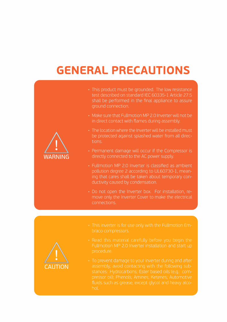
• This product must be grounded. The low resistancetest described on standard IEC 60335-1 Article 27.5shall be performed in the final appliance to assureground connection.
• Make sure that Fullmotion MP 2.0 Inverter will not bein direct contact with flames during assembly.
• The location where the Inverter will be installedmustbe protected against splashed water from all direc-tions.
• Permanent damage will occur if the Compressor isdirectly connected to the AC power supply.
• Fullmotion MP 2.0 Inverter is classified as ambientpollution degree 2 according to UL60730-1, mean-ing that cares shall be taken about temporary con-ductivity caused by condensation.
• Do not open the Inverter box. For installation, re-move only the Inverter Cover to make the electricalconnections.
!!WARNING
!!
NOTICE
CAUTION
!!
• This inverter is for use only with the Fullmotion Em-braco compressors.
• Read this material carefully before you begin theFullmotion MP 2.0 Inverter installation and start upprocedure.
• To prevent damage to your inverter during and asterassembly, avoid contacting with the following sub-stances: Hydrocarbons; Ester based oils (e.g.: com-pressor oil); Phenols; Amines; Ketenes; Automotivefluids such as grease, except glycol and heavy alco-hol.

Chapter 1
INTRODUCTION
Embraco's Variable Capacity Compressors MP 2.0 is ideal for commercial applica-tions where wide voltage range, fast pull down, better performance, fine tempera-ture control, lower power consumption and very low noise and vibration levels arerequired. This is possible thanks to the use of an electronic inverter capable ofdriving the compressor at different speeds and consequently, controlling its refrig-eration capacity.
Efficiency
Variable Capacity Compressors technol-ogy allows the compressor to operate atdifferent speeds, adjusting itself accord-ing to demand. When side by side with aconventional compressor, the energy con-sumption is up to 45%.
Flexible
Indicated for commercial refrigerationsystem, provides more flexibility in cus-tomized solutions through inclusion ofeven smaller products and the use ofelectronics already coupled to the com-pressor.
1

CHAPTER 1. INTRODUCTION 2
1.1 Product description
1.1.1 Stand alone
1
2
3
4
Figure 1.1: Stand alone view.
Composed by
Indicator Description
1Plastic and aluminum
body2 Plastic base3 Plastic cover4 Connection cables*
*View product datasheet.
1.2 Package information
The inverters are packed in a carton paper box. Figure 1.2 shows the used box topack the product. The quantity of products inside the box may change due to in-ternal or external requirements. Box dimensions can be changed without previousinformation.
575395
165
Figure 1.2: Product package.

CHAPTER 1. INTRODUCTION 3!!
WARNING
!!
NOTICE
CAUTION
!!
• Before you begin your installation observetechnical specifications and proper connec-tions.
• Check if product is properly identified and ifit's enclosure is without cracks.
1.3 Product handling
!!WARNING
!!
NOTICE
CAUTION
!!
• Inverter is sensitive to Electrostatic Dis-charges. Take care with product handlinguntil final assembly.
• Special care must be taken to avoid me-chanical impacts on the inverter during as-sembly process.
• The environment must be properly pro-tected against ESD.
• The workers that handle the inverter mustbe grounded through adequate ESD wriststrap and must wear ESD gloves.
• Do not hold by the wiring.
• Do not use if drop the inverter.
1.4 Institute approval
Institute approval
Fullmotion MP 2.0Inverter
Approved according toUL60730-1 ed. 4. Fileref. E222315, Volume 3,
Section 3.
Chapter 2
TECHNICAL SPECIFICATIONS
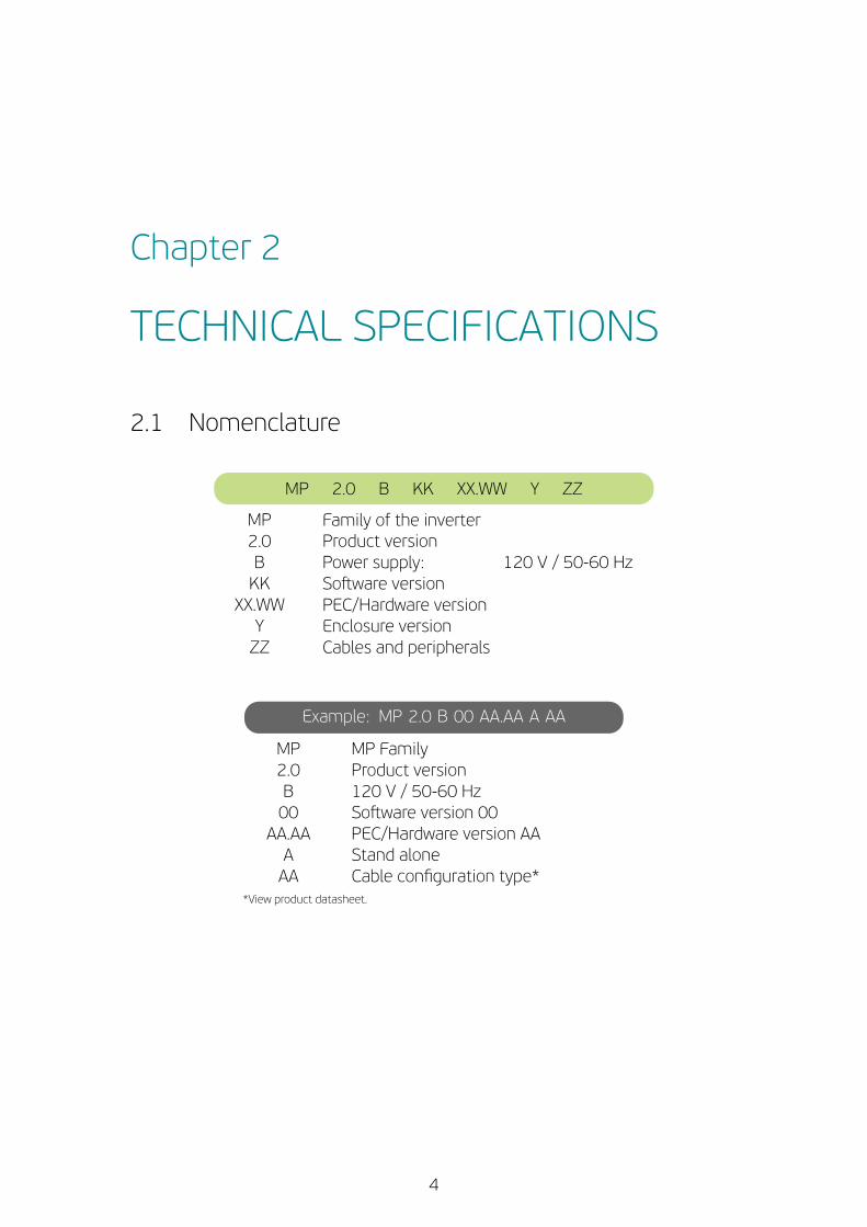
2.1 Nomenclature
MP 2.0 B KK XX.WW Y ZZ
MP Family of the inverter2.0 Product versionB Power supply: 120 V / 50-60 HzKK Sostware version
XX.WW PEC/Hardware versionY Enclosure versionZZ Cables and peripherals
Example: MP 2.0 B 00 AA.AA A AA
MP MP Family2.0 Product versionB 120 V / 50-60 Hz00 Sostware version 00
AA.AA PEC/Hardware version AAA Stand aloneAA Cable configuration type*
*View product datasheet.
4

CHAPTER 2. TECHNICAL SPECIFICATIONS 5
2.1.1 Label information
Next image shows the product label description.
MP 2.0 B 00 AA.AA A AA ROHSEG
SDMGY001D20
Input 120 V /50-60 Hz 8.0 A 2/3 1PHOutput 230 V-60 to 150 Hz 3.3 A hp 3PH
51XXXXXXX QD DD/MMM/YY XXXXXXX XXX
Manufacturer code ↑ ↑ Batch code / Serial number
Production site Production date
2.2 Product Specifications
Electrical
Voltage rating 120 VVoltage range 70 to 140 V
Input frequency range 50 Hz to 60 HzMaximum input current 8 AMaximum input power 540 WStand by consumption < 0.9 WOutput frequency range 60 Hz to 150 HzMaximum output current 3.3 AMaximum output power 500 W
Control modes Frequency, Drop-In and Serial
Compressor
Compressor* VEGT11HB or VEGT8UCompressor speed range* 1800 rpm to 4500 rpm
Ambient and Storage
Air forced ventilation (min) 2 m/sAmbient temp. range -20 ºC to 60 ºCAmbient humidity < 85%
Storage temp. range -40 ºC to 85 ºCStorage humidity Less than 85%
*View product datasheet.
CHAPTER 2. TECHNICAL SPECIFICATIONS 6
!!WARNING
!!
NOTICE
CAUTION
!!
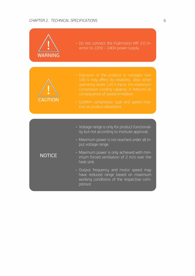
• Do not connect the Fullmotion MP 2.0 In-verter to 220V – 240V power supply.
!!WARNING
!!
NOTICE
CAUTION
!!
• Exposure of the product to voltages over140 V may affect its reliability. Also, whenoperating under 120 V input, the maximumcompressor cooling capacity is reduced asconsequence of speed limitation.
• Confirm compressor type and speed rota-tion at product datasheet.
!!WARNING
!!
NOTICE
CAUTION
!! • Voltage range is only for product functional-ity but not according to institute approval.
• Maximum power is not reached under all in-put voltage range.
• Maximum power is only achieved with min-imum forced ventilation of 2 m/s over theheat sink.
• Output frequency and motor speed mayhave reduced range based on maximumworking conditions of the respective com-pressor.
CHAPTER 2. TECHNICAL SPECIFICATIONS 7
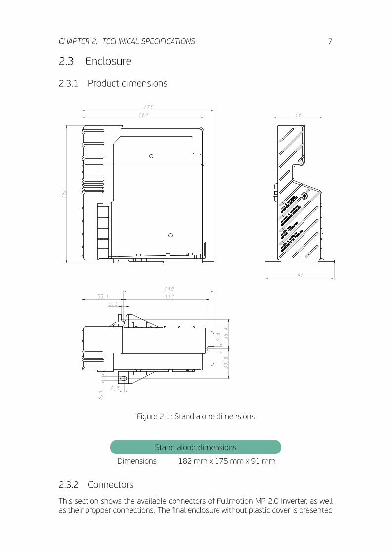
2.3 Enclosure
2.3.1 Product dimensions
175
162
182
91
66
113
38,4
39,6
55,1
119
2,5
5,5
5,5
5,5
Figure 2.1: Stand alone dimensions
Stand alone dimensions
Dimensions 182 mm x 175 mm x 91 mm
2.3.2 Connectors
This section shows the available connectors of Fullmotion MP 2.0 Inverter, as wellas their propper connections. The final enclosure without plastic cover is presented

CHAPTER 2. TECHNICAL SPECIFICATIONS 8
to improve understanding. The manufacturer part number of each connector canbe found bellow.
1
2
3
4
5
6
Figure 2.2: Connectors.
Connectors part numbers
Indicator Description Part number Manufacturer Insulation
1Serial
CommunicationS3P-VH (LF)(SN) JST Reinforced
2 & 3 Cables provided by Embraco
4 & 6Control and ACinput (L+N)
1217754-1 Tyco Functional
5 AC Fan*MSLO 9402 -002 - 00A - 960
- 000 - 00Stocko --
*Mates with 1/4'' faston receptacle.
CHAPTER 2. TECHNICAL SPECIFICATIONS 9
2
1
3
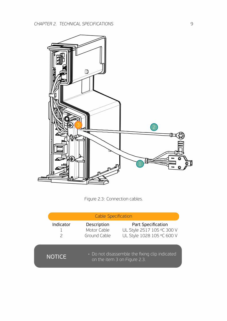
Figure 2.3: Connection cables.
Cable Specification
Indicator Description Part Specification1 Motor Cable UL Style 2517 105 ºC 300 V2 Ground Cable UL Style 1028 105 ºC 600 V
!!WARNING
!!
NOTICE
CAUTION
!!
• Do not disassemble the fixing clip indicatedon the item 3 on Figure 2.3.

CHAPTER 2. TECHNICAL SPECIFICATIONS 10
2.3.3 Product discards!!WARNING
!!
NOTICE
CAUTION
!!
• Do not open the inverter box.
• Do not incinerate any inverter. Contact yourlocal authorities, if you need to incineratethis product for disposal.
• Inverters should not be mixed with generalwaste.
!!WARNING
!!
NOTICE
CAUTION
!! • If you wish to discard this product, pleasecontact your local authorities or dealer forthe correct method of disposal, for propertreatment, recovery and recycling.
• This device is RoHS compliant, neverthelessthe correct disposal of this product will helpto save valuable resources and prevent anypotential negative effects on human healthand the environment (e.g.: to avoid grounddisperse) which could otherwise arise frominappropriate handling.

Chapter 3
INSTALLATION
3.1 Assembly instructions
3.1.1 Inverter
11

CHAPTER 3. INSTALLATION 12
3.1.2 Motor cable connection
The Fullmotion MP 2.0 Inverter has a quick and easy assembly method. To connectto the compressor the following sequence must be addopted.
1. Connect the motor cable on the hermetic compressor terminal;
2. Connect the Ground connector on the compressor ground terminal.
12
Figure 3.1: Compressor (1) and Ground (2) connectors
Figure 3.2: Step 1 Figure 3.3: Step 2
Aster performing the connections, assemble compressor fence cover as shown inthe following sequence (Step 3 and 4).
Figure 3.4: Step 3 Figure 3.5: Step 4

CHAPTER 3. INSTALLATION 13
Figure 3.6: Perspective view of Inverter and Compressor assembled system.
To disassemble the fence conver, the following sequence must be addopted.
1. Introduce a screwdriver into the clip in the top of the fence cover and push itdown;
2. To remove the cover, push it down and pull out of the compressor.
INSTRUÇÕES DE MONTAGEM DE COMPONENTES ELÉTRICOS
INFORMATIVO TÉCNICO
CÓDIGO 05006 - OUTUBRO/06 - REVISÃO No. 01
Para a retirada fi nal da tampa, pressione-a para baixo, afastando-a do compressor (veja fi gura 12).
Figura 12
1
2
Figura 11
1
2
7 - PROCEDIMENTO DE MONTAGEM E DESMONTAGEMDA NOVA TAMPA DO RELÉ (EM e F/EG)
Após a montagem do dispositivo de partida e do protetor térmico, faça as conexões elétricas.
Na seqüência, a tampa deve ser apoiada de forma que se encaixe nas abas laterais e superior do fence conforme fi gura 13, observado o alinhamento adequado da mesma.
Insira então o prendedor de cabos no alojamento, garantindo que o cabeamento esteja na posição adequada (fi gura 14), parafusando com um torque de 1,2 N.m.
A seguir a tampa deve ser pressionada contra o compressor até se ouvir o estalo característico de encaixe.
Figura 14
PÁGINA 04 DE 06
Figura 13
Para desmontar a tampa é necessário introduzir uma chave de fenda na lingüeta de desencaixe localizada na face superior da tampa (veja fi gura 11) e pressionar a chave de fenda para baixo, até que o ressalto fi que liberado do rasgo da base.
Figure 3.7: Step 1
INSTRUÇÕES DE MONTAGEM DE COMPONENTES ELÉTRICOS
INFORMATIVO TÉCNICO
CÓDIGO 05006 - OUTUBRO/06 - REVISÃO No. 01
Para a retirada fi nal da tampa, pressione-a para baixo, afastando-a do compressor (veja fi gura 12).
Figura 12
1
2
Figura 11
1
2
7 - PROCEDIMENTO DE MONTAGEM E DESMONTAGEMDA NOVA TAMPA DO RELÉ (EM e F/EG)
Após a montagem do dispositivo de partida e do protetor térmico, faça as conexões elétricas.
Na seqüência, a tampa deve ser apoiada de forma que se encaixe nas abas laterais e superior do fence conforme fi gura 13, observado o alinhamento adequado da mesma.
Insira então o prendedor de cabos no alojamento, garantindo que o cabeamento esteja na posição adequada (fi gura 14), parafusando com um torque de 1,2 N.m.
A seguir a tampa deve ser pressionada contra o compressor até se ouvir o estalo característico de encaixe.
Figura 14
PÁGINA 04 DE 06
Figura 13
Para desmontar a tampa é necessário introduzir uma chave de fenda na lingüeta de desencaixe localizada na face superior da tampa (veja fi gura 11) e pressionar a chave de fenda para baixo, até que o ressalto fi que liberado do rasgo da base.
Figure 3.8: Step 2

CHAPTER 3. INSTALLATION 14
!!WARNING
!!
NOTICE
CAUTION
!!
• Before obtain access to connectors, discon-nect the AC power supply.
• Avoid contact of the Control Input Cable (lowvoltage) with high voltage or power supplycables, due to electrical hazard and potentialequipment damage.
!!WARNING
!!
NOTICE
CAUTION
!!
• Motor connector must be properly mountedon the 3 pins of compressor hermetic ter-minal. Bad connection will cause bad com-pressor functioning.
• The screws shown in Figure 3.5 must befixed with a torque within 0.8 – 1.2 Nmrange.
• The handling of Inverter box must be carefulto avoid contact with the internal electronicboard, in order to prevent possible electro-static discharges.
• Make sure all necessary connections areproperly done before connecting the In-verter to AC supply line.
• The electronic Inverter must be installed inthe vertical position.
• When using Serial or Frequency communi-cation mode, the inverter has reinforced iso-lation. Neverthless, in the Drop-Inmode (en-ergized or dry-contact) this functionality isnot available.
• Ground connector must be properly assem-bled until the terminal locks.
• To disconnect the motor cable, insert ascrewdriver between the connector and thecompressor terminal to make a lever andthen pull it back.
CHAPTER 3. INSTALLATION 15
!!WARNING
!!
NOTICE
CAUTION
!!
• It is necessary to read the Embraco com-pressor documents that contain technicalinformation about the Fullmotion compres-sors, not covered in this material. Please,contact the compressor technical assitant.
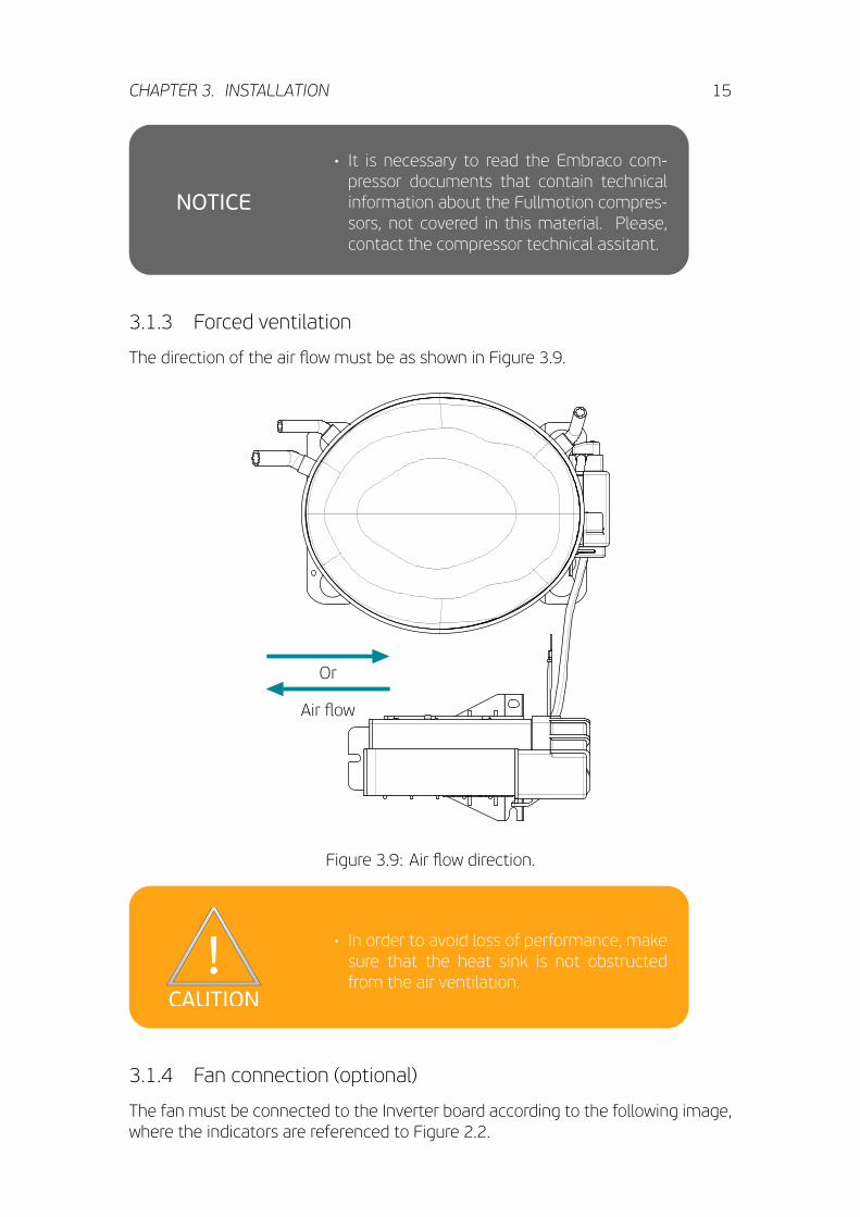
3.1.3 Forced ventilation
The direction of the air flow must be as shown in Figure 3.9.
Or
Air flow
Figure 3.9: Air flow direction.
!!WARNING
!!
NOTICE
CAUTION
!!• In order to avoid loss of performance, makesure that the heat sink is not obstructedfrom the air ventilation.
3.1.4 Fan connection (optional)
The fan must be connected to the Inverter board according to the following image,where the indicators are referenced to Figure 2.2.

CHAPTER 3. INSTALLATION 16
MP 2.0 INVERTERMP 2.0 INVERTER
FAN
Phase5 FAN
Phase
Neutral6 LNeutral6 N
Figure 3.10: Fan connection.
!!WARNING
!!
NOTICE
CAUTION
!!• The maximum voltage of the inverter relayis 250 V.
• The maximum current of the inverter relayis 1.5 A.
3.1.5 Input, Fan and Communication cables arrangement
The input, fan and communication cables are not provided by Embraco. Further-more, the customermust arrange the cables according to the following instructions.
1. Break the plastic protection as much as necessary to pass the cables. Thecables must pass through the cord relief as shown in Figure 3.11
2. Assemble the fixing clip as shown in Figure 3.12.
Routing Description
Indicator Description1 Input Cable2 Fan Cable3 Communication Cable4 Fixing Screw

CHAPTER 3. INSTALLATION 17
3
2
1
Figure 3.11: Step 1
4
Figure 3.12: Step 2!!WARNING
!!
NOTICE
CAUTION
!!
• Avoid routing cables over the cord relief, oth-erwise the product may damage due to me-chanical stress.
• The screw shown in Figure 3.12 must befixed with a torque within 0.8 - 1.2 Nm.
• Aster concluded the routing, the plasticcover must be reassembled, fixing the scewwith a torque between 0.8 - 1.2 Nm.

Chapter 4
OPERATION
The Fullmotion MP 2.0 Inverter has 3 communication mode available: Drop-In, Fre-quency and Serial. For all the available control modes, the fan relay is turned onautomaticaly, whenever the compressor is running.
!!WARNING
!!
NOTICE
CAUTION
!!• The Control Mode is chosen by the cus-tomer and configured at the EMBRACOELECTRONICS manufacturing line.
4.1 Frequency control mode
In this mode of operation the compressor speed is controled through a frequencysignal sent to the inverter. Usually this signal is provided by an electronic thermo-stat.The frequency signal is a digital square wave and its characteristics are describedon Signal specification table and Figure below.
Signal specifications
Voltage range -5 V to +15 VOFF state -5 V to +0.7 VON state +5 V to +15 V
Maximum duty-cycle 70%Minimum duty-cycle 30%Maximum current 15 mA @ 15 V –5
0.7
5
15
Off state
Indefinite state
On state
Once the range from 0.7 V to 4.5 V is an indefinite state, it's recommended to avoidit. The following graphic shows an example of an input frequency signal of 100 Hzsent to the inverter. The duty-cycle of the digital frequency wave can vary from 30%to 70%.
18
CHAPTER 4. OPERATION 19
0 2 4 6 8 10 12 14 16 18 20 22
0
5
10
15
Time [ms]
Amplitude
[V]
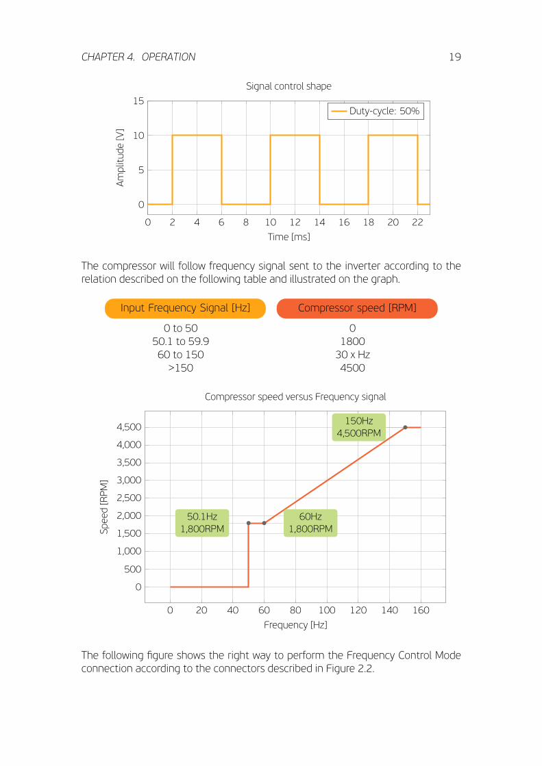
Signal control shape
Duty-cycle: 50%
The compressor will follow frequency signal sent to the inverter according to therelation described on the following table and illustrated on the graph.
Input Frequency Signal [Hz] Compressor speed [RPM]
0 to 50 050.1 to 59.9 180060 to 150 30 x Hz>150 4500
0 20 40 60 80 100 120 140 160
0
500
1,000
1,500
2,000
2,500
3,000
3,500
4,000
4,500
50.1Hz1,800RPM
60Hz1,800RPM
150Hz4,500RPM
Frequency [Hz]
Speed[RPM]
Compressor speed versus Frequency signal
The following figure shows the right way to perform the Frequency Control Modeconnection according to the connectors described in Figure 2.2.

CHAPTER 4. OPERATION 20
MP 2.0 INVERTEREletronic
ThermostatMP 2.0 INVERTER4 Frequency SignalInput (+)
Common (-)-+
Phase
Neutral6 LNeutral6 N
Figure 4.1: Frequency control mode connetion
!!WARNING
!!
NOTICE
CAUTION
!!
• For Frequency Control Mode, the input resis-tance is 1.2 kΩ.
4.2 Drop-In control mode
The Drop-In mode is a Fullmotion MP 2.0 Inverter control mode, where single ther-mostat contact is used to set the compressor running conditions. Drop-In modeallows the application to any refrigeration system with a simple ON/OFF thermo-stat, without needing a control signal coming from an electronic thermostat. Thecompressor speed will be adjusted automatically by the Inverter, in accordance tothe thermal load variation.
4.2.1 First time Pull-down
Aster 7 minutes of intermediary speed, the speed is increased to maximum and itis kept at this rotation until the thermostat opens, switching the compressor off.
4.2.2 Normal cycling
Compressor speed increases and decreases proportional to thermal load variationduring compressor running time. Minimum speed will be targeted to minimize en-ergy consumption.
CHAPTER 4. OPERATION 21
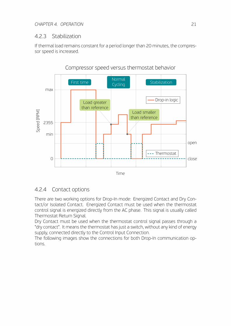
4.2.3 Stabilization
If thermal load remains constant for a period longer than 20 minutes, the compres-sor speed is increased.
0
min
2355
max
First timeNormalCycling Stabilization
Load greaterthan reference
Load smallerthan reference
Time
Speed[RPM]
Compressor speed versus thermostat behavior
Drop-in logic
close
open
Thermostat
4.2.4 Contact options
There are two working options for Drop-In mode: Energized Contact and Dry Con-tact/or Isolated Contact. Energized Contact must be used when the thermostatcontrol signal is energized directly from the AC phase. This signal is usually calledThermostat Return Signal.Dry Contact must be used when the thermostat control signal passes through a"dry contact". It means the thermostat has just a switch, without any kind of energysupply, connected directly to the Control Input Connection.The following images show the connections for both Drop-In communication op-tions.

CHAPTER 4. OPERATION 22
MP 2.0 INVERTERMP 2.0 INVERTER4 Control “+”+
Phase
Neutral6
On/Off Thermostat
LNeutral6 N
Figure 4.2: Energized Contact Drop-Inconnections.
MP 2.0 INVERTER On/Off( )MP 2.0 INVERTER On/Off Thermostat
4 Input (+)
Common (-)-+
Phase
Neutral6 LNeutral6 N
Figure 4.3: Dry Contact Drop-In connec-tions.
!!WARNING
!!
NOTICE
CAUTION
!!• When opened, the thermostat impedancemust be higher than 380 kΩ. Otherwise thecompressor can run continuously, withoutever turning off.
!!WARNING
!!
NOTICE
CAUTION
!!
• All main parameters, such as minimum andmaximum speed are described at productdatasheet.
4.3 Serial control mode
This option is used when an electronic thermostat controls the MP 2.0 Inverter us-ing a serial communication protocol. Based on Embraco protocol it is possible todefine the compressor speed and check other parameters.
4.3.1 Serial specifications and Internal Circuit
The Serial Control mode has an isolated input stage provided by the usage of op-tocouplers. The circuit on Figure 4.4 shows the electrical connections to performserial communication between an electronic thermostat and Fullmotion MP 2.0 In-verter serial connector (CN203).The input resistance for serial comunication, shown in Figure 4.4, is 1.2 kΩ.

CHAPTER 4. OPERATION 23
1
1
2
2
3
3
4
4
D D
C C
B B
A A
Title
Number RevisionSize
A4
Date: 06/08/2015 Sheet ofFile: C:\Arthur\..\Sheet_Manual Drawings.SchDocDrawn By:
VCC
VCC
1
32
CN 203
1.2 kΩ
Maximum collector
PIN 1 - Signal from Thermostat
1
32
CN 203
PIN 2 - Thermostat GND
Recommended circuit for
serial communicationPIN 3 - Signal to Thermostat
CN 203 pinout:
3.9 kΩVCC
Thermostat TX
Thermostat RX
current: 15 mA
PIC40101PIC40102
COC401
PICN20301
PICN20302
PICN20303
COCN 203
PID101
PID102COD1
PID40101
PID40102COD401
PIJ401
PIJ402COJ4
PIJ00601
PIJ00602
COJ006
PIOPTOCOUPLER101
PIOPTOCOUPLER102 PIOPTOCOUPLER103
PIOPTOCOUPLER104COOPTOCOUPLER1
PIOPTOCOUPLER 201
PIOPTOCOUPLER 202PIOPTOCOUPLER 203
PIOPTOCOUPLER 204COOPTOCOUPLER 2
PIPT301 COPT3PIPT1001
COPT10
PIPT1201COPT12
PIPT4201
COPT42
PIQ101
PIQ102
PIQ103COQ1
PIR00?01 PIR00?02
COR00?
PIR00101 PIR00102
CO102 k?
PIR40201 PIR40202
COR402
PIR40301 PIR40302
COR403
PIR40501 PIR40502
COR405
PIR40801
PIR40802COR408
PIR40901
PIR40902COR409
Inverter board
Figure 4.4: Electrical schematic of serial communication.
To guarantee the correct functionality of serial comunication, the signal sent to theinverter must be according to the following values.
Signal specifications
Voltage range -5 V to +15 VTRUE state -5 V to +0.7 VFALSE state +5 V to +15 V
Maximum current 15 mA @ 15 V–5
0.7
5
15
TRUE state
Indefinite state
FALSE state
↑
Startbit
Data bitsStopbit
0 1 2 3 4 5 6 7
FALSE TRUE FALSE FALSE TRUE TRUE TRUE FALSE FALSE TRUE
Time
Amplitude
[V]
Example: 39h sent to inverter
The identification byte (1st byte), is used for command synchronization. Aster in-verter identifies a valid A5h, it starts to read the next 4 bytes. Aster reading, a re-
CHAPTER 4. OPERATION 24
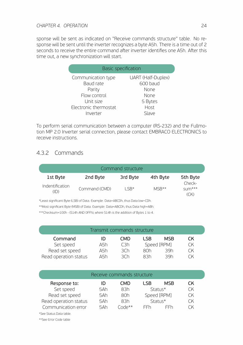
sponse will be sent as indicated on ''Receive commands structure'' table. No re-sponse will be sent until the inverter recognizes a byte A5h. There is a time out of 2seconds to receive the entire command aster inverter identifies one A5h. Aster thistime out, a new synchronization will start.
Basic specification
Communication type UART (Half-Duplex)Baud rate 600 baudParity None
Flow control NoneUnit size 5 Bytes
Electronic thermostat HostInverter Slave
To perform serial communication between a computer (RS-232) and the Fullmo-tion MP 2.0 Inverter serial connection, please contact EMBRACO ELECTRONICS toreceive instructions.
4.3.2 Commands
Command structure
1st Byte 2nd Byte 3rd Byte 4th Byte 5th Byte
Indentification(ID)
Command (CMD) LSB* MSB**Check-sum***(CK)
*Least significant Byte (LSB) of Data. Example: Data=ABCDh, thus Data low=CDh.
**Most significant Byte (MSB) of Data. Example: Data=ABCDh, thus Data high=ABh.
***Checksum=100h - (S14h AND 0FFh), where S14h is the addition of Bytes 1 to 4.
Transmit commands structure
Command ID CMD LSB MSB CKSet speed A5h C3h Speed [RPM] CK
Read set speed A5h 3Ch 80h 39h CKRead operation status A5h 3Ch 83h 39h CK
Receive commands structure
Response to: ID CMD LSB MSB CKSet speed 5Ah 83h Status* CK
Read set speed 5Ah 80h Speed [RPM] CKRead operation status 5Ah 83h Status* CKCommunication error 5Ah Code** FFh FFh CK
*See Status Data table.
**See Error Code table

CHAPTER 4. OPERATION 25
Status Data
H Bit LSB MSB Description- - 00h Compressor running- - FFh Compressor stopped0 01h - Start fail1 02h - Overload2 04h - Under speed (1550 rpm or lower)4 10h - Short circuit5 20h - Over temperature7 80h - Set speed out of range
Error Code
Code ErrorF0h Error in 4th ByteF2h Checksum errorF4h Command erroF8h Error in the 3rd Byte
If compressor is stopped due to a fail (see Data Status table), it is possible to resetthat fail sending a speed command to turn inverter off (0 rpm set speed). However,if nothing is done, the fail reset will occur aster 8 minutes and then the compressorwill try to restart. The following example shows a situation where the compressorspeed is set at 1800 RPM.
Example: Set compressor at 1800 RPM
Step 1: select proper commandCommand for selecting a speed is Set speedID→A5hCMD→C3h
Step 2: transform speed from decimal into hexadecimal base1800d→0708h
Step 3: split lower and higher BytesLSB→08hMSB→07h
Step 4: calculate sum of first 4 BytesS14h=A5h+C3h+08h+07hS14h→177h
Step 5: boolean logic to maintain sum as 8-bitL14h=0FFh AND S14hL14h→77h
Step 6: calculate checksumCK=100h-(0FFh AND S14h)=100h-77hCK=→89h
Command: A5h C3h 08h 07h 89h

CHAPTER 4. OPERATION 26
!!WARNING
!!
NOTICE
CAUTION
!! • To avoid noise increasing and damages tothe compressor due to mechanical reso-nance, some rotations tracks are forbiddenby sostware for all control modes.
• When one or more errors occur, the corre-sponding “H” bits are set to 1. Example:Overload and Under speed LSB→06h.
• The Frequency and Drop-In modes can haveserial communication only for monitoringpurpose. This functionality can be used forproduct diagnostic.

Chapter 5
DIAGNOSTICS
The Fullmotion MP 2.0 Inverter has two diagnostics methods, by visual light emis-sion using a LED indication, or by serial communication protocol.
5.1 LED indication
The LED diagnostic unitcan be seen through thetranslucent cover, which alsoprovides the basic infor-mation for diagnostic. Thisfunction helps services tech-nicians to diagnose possiblefault components by blinkinga green, orange or red LEDinside the box. Basically itindicates if there is a prob-lem with Compressor, MP 2.0Inverter or Thermostat. Thetable below describes thefailure modes.
LED Status Period Description
1 Green Flash 30 seconds Normal operation4 Green Flashes 5 seconds Communication problem4 Red Flashes 5 seconds Inverter problem
4 Orange Flashes 5 seconds Compressor problem
27

CHAPTER 5. DIAGNOSTICS 28
5.2 Serial monitoring
For both Drop-In (energized and dry-contact) and Frequency control modes, there'sthe possibility of performing a serial communication. For both control modes, thiscommunication is only for monitoring purpose. The electrical connections shall beperformed as represented in Figure 5.1 and Figure 5.2.
Monitoringtooltool
Out
GNDIn
Serial Signal1
ERIA
L
InSE
MP 2.0 INVERTEREletronic
ThermostatMP 2.0 INVERTERFrequency SignalInput (+)
Common (-)
4-
+
Phase
Neutral6 LNeutral6 N
Figure 5.1: Serial connection for monitoring Frequency control mode
Monitoringtooltool
Serial Signal
Out
GNDIn
1
ERIA
L
InSE
MP 2.0 INVERTERMP 2.0 INVERTER4 Control “+”+
Phase
Neutral6
On/Off Thermostat
LNeutral6 N
Figure 5.2: Serial connection for monitoring energized Drop-In control mode
!!WARNING
!!
NOTICE
CAUTION
!!
• For monitoring serial mode, the set speedcommand is not available.

CHAPTER 5. DIAGNOSTICS 29
5.3 Troubleshooting
The following tables shows some possible problems and the best action to deal withthem.
Compressor does not start
Problem Action
Compressor disconnected from theinverter. ·Verify compressor cable connection.
No AC power supply; or wrongvoltage/terminals connected.
·Verify AC input cable connection andmeasure AC input voltage.
No control signal input or badconnection.
·Verify control input cable connectionand measure the signal from thethermostat.
Blown fuse (due to previous majorfailure).
·Return the unit to manufacturer,replacing it by new one.
Open compressor motor winding.
·Measure winding for open circuitbetween all pair of pins on the hermeticterminal. If any winding is open, returncompressor to manufacturer.
Compressor with locked rotor (due tomechanical damage).
·Replace compressor by new one andtest for confirmation. Return damagedunit to manufacturer.
Dropped, damaged, burnt inverter.·Replace by new one and test forconfirmation. Return damage unit tomanufacturer.
Inverter on waiting time aster failed start.
·Wait the necessary time or reset theinverter disconnecting it from the ACpower supply. The reset time is about50s.
Demagnetized rotor (only if compressorwas previously connected directly to the
AC power supply).
·Replace compressor by a new one andtest for confirmation. Return damagedunit to manufacturer.
Unequaled pressures between dischargeand suction pressures in the refrigerating
system.
·Allow the Inverter to equalize pressurebetween suction and discharge sides.
Low input voltage supplied to theinverter. ·Measure AC voltage to confirm.
CHAPTER 5. DIAGNOSTICS 30
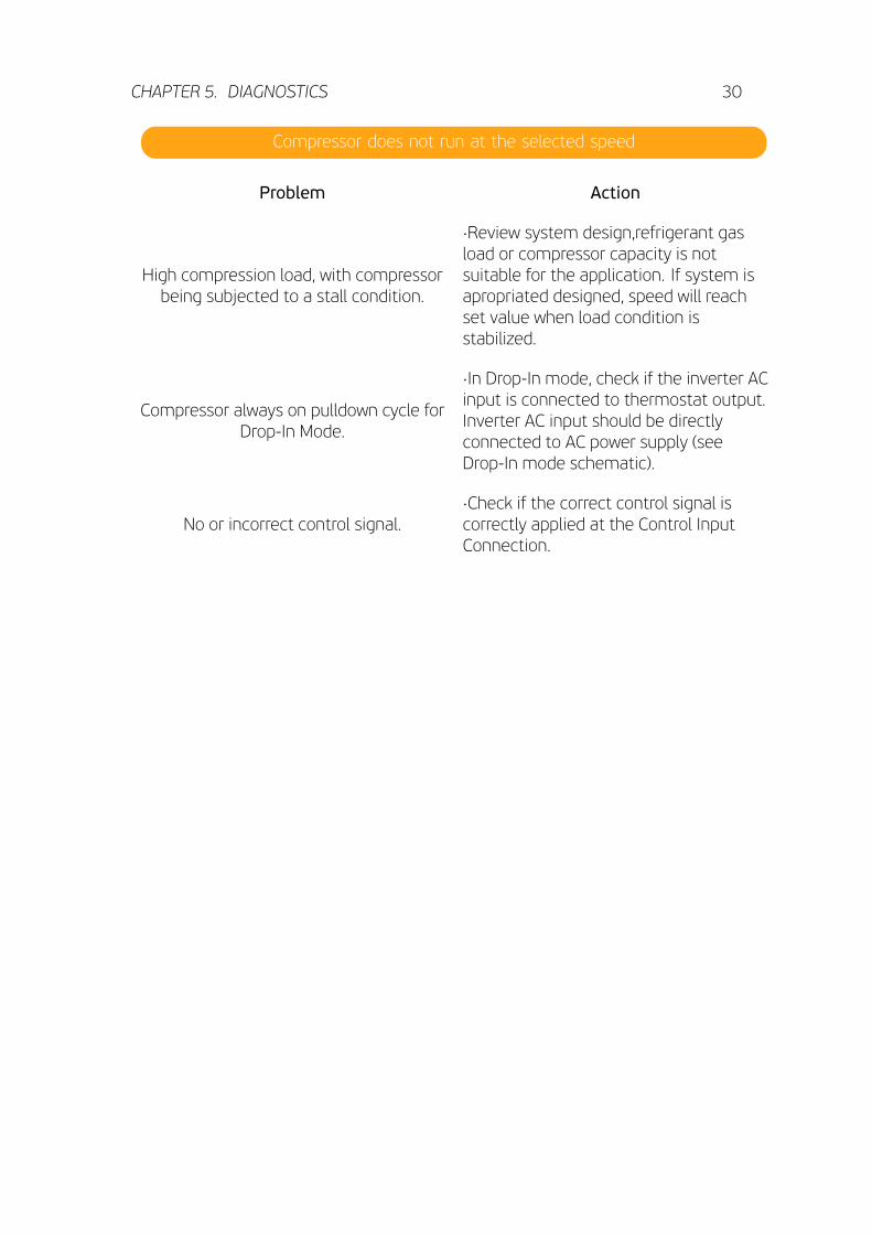
Compressor does not run at the selected speed
Problem Action
High compression load, with compressorbeing subjected to a stall condition.
·Review system design,refrigerant gasload or compressor capacity is notsuitable for the application. If system isapropriated designed, speed will reachset value when load condition isstabilized.
Compressor always on pulldown cycle forDrop-In Mode.
·In Drop-In mode, check if the inverter ACinput is connected to thermostat output.Inverter AC input should be directlyconnected to AC power supply (seeDrop-In mode schematic).
No or incorrect control signal.·Check if the correct control signal iscorrectly applied at the Control InputConnection.

DISCLAIMERThe Fullmotion MP 2.0 Inverter is for use only with the Embraco compressors.ALL PRODUCT, PRODUCT SPECIFICATIONS AND DATA ARE SUBJECT TO CHANGEWITHOUT NOTICE TO IMPROVE RELIABILITY, FUNCTION OR DESIGN OR OTHER-WISE.Embraco, its affiliates, agents, and employees, and all persons acting on its or theirbehalf (collectively, “Embraco”), disclaim any and all liability for any errors, inaccu-racies or incompleteness contained in any datasheet or in any other disclosure re-lating to any product. Embraco makes no warranty, representation or guaranteeregarding the suitability of the products for any particular purpose or the continu-ing production of any product. To the maximum extent permitted by applicable law,Embraco disclaims (i) any and all liability arising out of the application or use of anyproduct, (ii) any and all liability, including without limitation special, consequentialor incidental damages, and (iii) any and all implied warranties, including warrantiesof fitness for particular purpose, non-infringement and merchantability.Statements regarding the suitability of products for certain types of applicationsare based on Embraco’s knowledge of typical requirements that are o en placedon Embraco products in generic applications. Such statements are not bindingstatements about the suitability of products for a particular application. It is thecustomer’s responsibility to validate that a particular product with the propertiesdescribed in the product specification is suitable for use in a particular application.Parameters provided in datasheets and/or specificationsmay vary in different appli-cations and performance may vary over time. All operating parameters, includingtypical parameters, must be validated for each customer application by the cus-tomer’s technical experts. Product specifications do not expand or otherwise mod-ify Embraco’s terms and conditions of purchase, including but not limited to thewarranty expressed therein. Except as expressly indicated in writing, Embraco prod-ucts are not designed for use in medical, life-saving, or life-sustaining applicationsor for any other application in which the failure of the Embraco product could resultin personal injury or death. Customers using or selling Embraco products not ex-pressly indicated for use in such applications do so at their own risk. Please contactauthorized Embraco personnel to obtain written terms and conditions regardingproducts designed for such applications.No license, express or implied, by estoppelor otherwise, to any intellectual property rights is granted by this document or byany conduct of Embraco. Product names and markings noted herein may be trade-marks of their respective owners. All trademarks in this material are property of therespective companies. EMBRACO is trademark of Whirlpool S/A.All rights reserved.

CONTACTIf aster these instructions you still have doubts, pleasedo not hesitate to contact our Technical Support.
www.embraco.com