vaultic405 s ummary datasheet - insiderus.ruinsiderus.ru/upload/file/summaryvic405_6614bs.pdf ·...
TRANSCRIPT

VAULTIC405 SUMMARY DATASHEET
66
14B
S –
13O
ct14
General FeaturesCryptographic Services
• Public Key Pair Generation
• Digital Signature
• Encryption / Decryption
• Message Digest
• Key Wrapping / Unwrapping
• True Random Number Generation
Cryptographic Algorithms
• DES / 3DES
• AES 128/192/256 bits
• RSA® up to 4096 bits*
• DSA up to 2048 bits
• ECC up to 384 bits
Software Features
• FIPS 140-2 Identity-based authentication using pass-word, Secure Channel Protocol (SCP02 / SCP03) orMicrosoft® Smart Card Minidriver strong authentication
• Rights Management (Administrator, Approved User,Non-approved User...)
• Embedded Dynamic FAT12 File System
Memory
• File System 16 Kbytes
• Write Endurance 500 Kcycles / Data Retention 20 Years
• 2ms Program + 2ms Erase
Communication
• USB 2.0 Full Speed Certified, USB CCID compliant
• Slave SPI Serial Interface, INSIDE’s Proprietary Proto-col
• I²C (Two Wire Interface), INSIDE’s Proprietary Protocol
2|22 VaultIC405 Summary Datasheet
Packages
• QFN20 (RoHS compliant) 4mm x 4mm
• SOIC8 (RoHS compliant) 5mm x 5mm
Hardware Platform
• 8-/16-bit RISC CPU
• Hardware Random Number Generator
• Hardware 3DES Crypto Accelerator (112-bits keys)
• Hardware AES Crypto Accelerator
• Hardware 32-bit Public Key Crypto Accelerator
Certifications / Standards
• EAL4+ Ready
• FIPS 140-2 Security Level 3
• Microsoft Smart Card Minidriver compliant
• SSL support
• PKCS#11
• Microsoft MS-CAPI
*Key sizes supported:
- Linear key size up to 2888 bits for CRT format only (2240 bits otherwise)
- 4096 bits for: CRT only Private exponent, Public exponent, CRT key generation.
66
14B
S –
13O
ct14
1. OverviewThe VaultIC405 is a secure microcontroller solution designed to secure various systemsagainst counterfeiting, cloning or identity theft. It is a hardware security module that can beused in many applications such as IP protection, access control or hardware protection.
The proven technology used in VaultIC405 security modules is already widespread andused in national ID/health cards, e-passports, bank cards (storing user Personal Identifica-tion Number, account numbers and authentication keys among others), pay-TV accesscontrol and cell phone SIM cards (allowing the storage of subscribers’ unique ID, PIN code,and authentication to the network), where cloning must definitely be prevented.
Strong Authentication capability, secure storage and flexibility thanks to the various inter-faces (USB, SPI, I²C), low pin count and low power consumption are main features of theVaultIC405. Its embedded firmware provides advanced functions such as Identity-basedauthentication, large Cryptographic command set, various Public domain cryptographicalgorithms, Cryptographic protocols, Secure Channel Protocols, Robust communicationprotocol.
1.1 Tamper resistanceINSIDE’s security modules will advantageously replace complex and expensive proprietaryanti-tampering protection system. Their advantages include low cost, ease of integration,higher security and proven technology.
They are designed to keep contents secure and avoid leaking information during code exe-cution. While on regular microcontrollers, measuring current consumption, radio emissionsand other side channels attacks may give precious information on the processed data orallow the manipulation of the data. INSIDE’s secure microcontrollers’ security featuresinclude voltage, frequency and temperature detectors, illegal code execution prevention,tampering monitors and protection against side channel attacks and probing. The chips candetect tampering attempts and erase sensitive data on such events, thus avoiding data con-fidentiality being compromised.
These features make cryptographic computations secure in comparison with regular micro-controllers whose memories can be easily duplicated. It is much safer to delegatecryptographic operations and storage of secret data (keys, identifiers, etc.) to an INSIDESecure microcontroller.
1.2 Authentication capabilityThe methods to authenticate humans are generally classified into three cases: physical attri-bute (e.g. fingerprint, retinal pattern, facial scan, etc.), security device (e.g. ID card, securitytoken, software token or cell phone) and something the user knows (e.g. a password/pass-phrase or a personal identification number).
To fight against identity theft, the multi-factor authentication is a stronger alternative to theclassical login/password authentication (called weak authentication). It combines two ormore authentication methods (often a password combined with a security token). Two-factorsystems greatly reduce the likelihood of fraud by requiring the presence of a physical deviceused together with a password. If the physical device is lost or the password is compro-mised, security is still intact. NIST’s authentication guideline [R2] can be referred to forfurther details.
Multi-factor authentication requires a strong authentication. Anticloning is safely imple-mented through one-way or mutual strong authentication. Various authentication protocolsexist (as specified in ISO9798-2 [R3] or FIPS196 [R4]), but the main method is the chal-lenge response authentication:
3|22 VaultIC405 Summary Datasheet
66
14B
S –
VIC
– 1
3O
ct1
4
1. The authenticator sends a challenge (e.g. a random number) to the equipment that must be authenticated (“the claimant”).
2. The claimant computes a digital signature of the combination of this challenge with an optional identifier, using a private or secret key. The requested signature is then returned to the authenticator.
3. The authenticator checks the signature using either the same secret key or the pub-lic key associated to the claimant’s private key and decides whether the claimant is authorized or not based on the signature verification result.
This strong authentication method requires storing secret data. Pure software multi-factorsolutions are thus not reliable.
1.3 Secure storageIf sensitive data is stored in files on a hard disk, even if those files are encrypted, the filescan be stolen, cloned and subjected to various kinds of attacks (e.g. brute force or dictionaryattack on passwords). Therefore secure microcontrollers-based hardware tokens are amust. Placing secrets outside the computer avoids risking exposure to malicious software,security breaches in web browsers, files stealing, etc.
1.4 FlexibilityThe VaultIC405 product features:
• Various communication interfaces including SPI (Serial Protocol Interface), I²C (Two Wire Interface) or USB (Universal Serial Bus).
• Low pin count (Vcc, GND, and communication interface specific pins) making integration into an existing board simple. VaultIC405 modules are available in small packages (SOIC8 or QFN20) to fit into the most size-constrained devices.
• Low power consumption, in order to extend battery life in portable devices and low-power systems. VaultIC405 devices consume less than 300µA in standby mode, and only 10 to 20mA during CPU-intensive operations depending on the required action.
• Embedded firmware that provides advanced functions:
– Secure storage: a fully user-defined non-volatile storage of 16KBytes forsensitive or secret data.
– Identity-based authentication with user, administrator and manufacturer rolessupported.
– Cryptographic command set to perform cryptographic operations using keys anddata from the file system including: authentication, digital signature,encryption/decryption, hash, one-time password generation, random generationand public key pair generation.
– Public domain cryptographic algorithms such as DES, 3DES, AES, RSAPKCS#1 v2.1, DSA, EC-DSA, MAC using DES, 3DES or AES
– Cryptographic protocols such as secret-key unilateral or mutual authentication[R3] and public key based unilateral or mutual authentication [R4].
– Secure Channel Protocol using 3DES or AES.
– Robust communication protocol stacked over the physical communicationinterfaces.
– Starter Kit with RSA PKCS#11 [R5] and Microsoft MS-CAPI [R6] libraries.
INSIDE Secure’s application note [R7] presents examples of efficient and cost effective IPprotection applications utilizing secure chips in various embedded systems.
4|22 VaultIC405 Summary Datasheet
66
14B
S –
13O
ct14
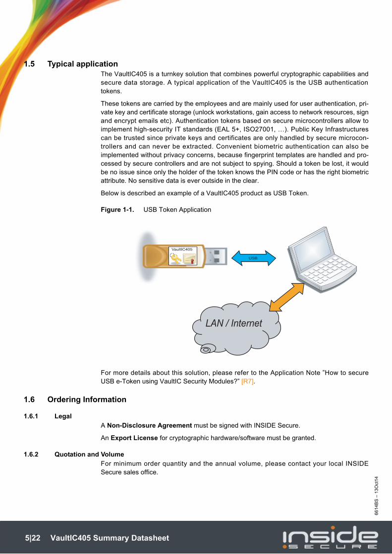
1.5 Typical applicationThe VaultIC405 is a turnkey solution that combines powerful cryptographic capabilities andsecure data storage. A typical application of the VaultIC405 is the USB authenticationtokens.
These tokens are carried by the employees and are mainly used for user authentication, pri-vate key and certificate storage (unlock workstations, gain access to network resources, signand encrypt emails etc). Authentication tokens based on secure microcontrollers allow toimplement high-security IT standards (EAL 5+, ISO27001, …). Public Key Infrastructurescan be trusted since private keys and certificates are only handled by secure microcon-trollers and can never be extracted. Convenient biometric authentication can also beimplemented without privacy concerns, because fingerprint templates are handled and pro-cessed by secure controllers and are not subject to spying. Should a token be lost, it wouldbe no issue since only the holder of the token knows the PIN code or has the right biometricattribute. No sensitive data is ever outside in the clear.
Below is described an example of a VaultIC405 product as USB Token.
Figure 1-1. USB Token Application
For more details about this solution, please refer to the Application Note ”How to secureUSB e-Token using VaultIC Security Modules?” [R7].
1.6 Ordering Information
1.6.1 Legal
A Non-Disclosure Agreement must be signed with INSIDE Secure.
An Export License for cryptographic hardware/software must be granted.
1.6.2 Quotation and Volume
For minimum order quantity and the annual volume, please contact your local INSIDESecure sales office.
LAN / Internet
VaultIC405
USB
5|22 VaultIC405 Summary Datasheet
66
14B
S –
VIC
– 1
3O
ct1
4
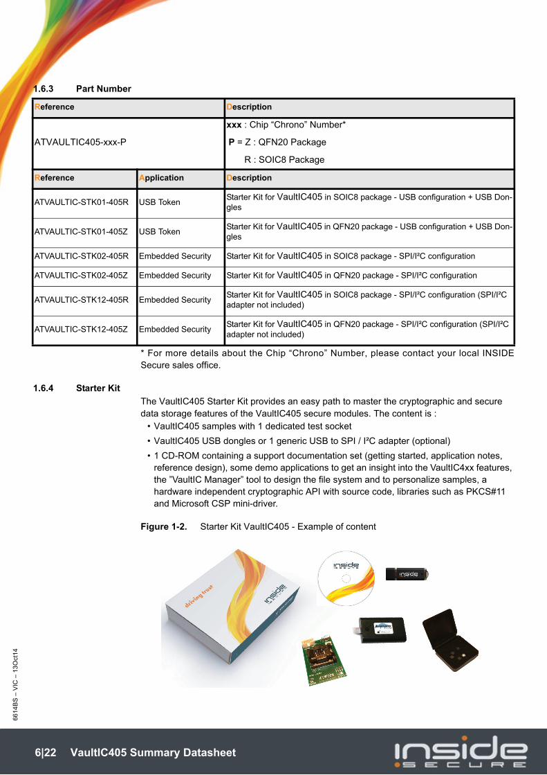
1.6.3 Part Number
* For more details about the Chip “Chrono” Number, please contact your local INSIDESecure sales office.
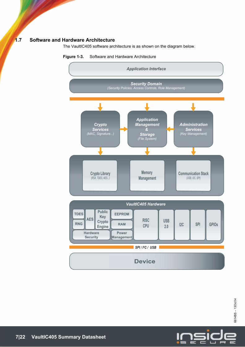
1.6.4 Starter Kit
The VaultIC405 Starter Kit provides an easy path to master the cryptographic and secure data storage features of the VaultIC405 secure modules. The content is :
• VaultIC405 samples with 1 dedicated test socket
• VaultIC405 USB dongles or 1 generic USB to SPI / I²C adapter (optional)
• 1 CD-ROM containing a support documentation set (getting started, application notes, reference design), some demo applications to get an insight into the VaultIC4xx features, the ”VaultIC Manager” tool to design the file system and to personalize samples, a hardware independent cryptographic API with source code, libraries such as PKCS#11 and Microsoft CSP mini-driver.
Figure 1-2. Starter Kit VaultIC405 - Example of content
Reference Description
ATVAULTIC405-xxx-P
xxx : Chip “Chrono” Number*
P = Z : QFN20 Package
R : SOIC8 Package
Reference Application Description
ATVAULTIC-STK01-405R USB TokenStarter Kit for VaultIC405 in SOIC8 package - USB configuration + USB Don-gles
ATVAULTIC-STK01-405Z USB TokenStarter Kit for VaultIC405 in QFN20 package - USB configuration + USB Don-gles
ATVAULTIC-STK02-405R Embedded Security Starter Kit for VaultIC405 in SOIC8 package - SPI/I²C configuration
ATVAULTIC-STK02-405Z Embedded Security Starter Kit for VaultIC405 in QFN20 package - SPI/I²C configuration
ATVAULTIC-STK12-405R Embedded SecurityStarter Kit for VaultIC405 in SOIC8 package - SPI/I²C configuration (SPI/I²C adapter not included)
ATVAULTIC-STK12-405Z Embedded SecurityStarter Kit for VaultIC405 in QFN20 package - SPI/I²C configuration (SPI/I²C adapter not included)
6|22 VaultIC405 Summary Datasheet
66
14B
S –
13O
ct14
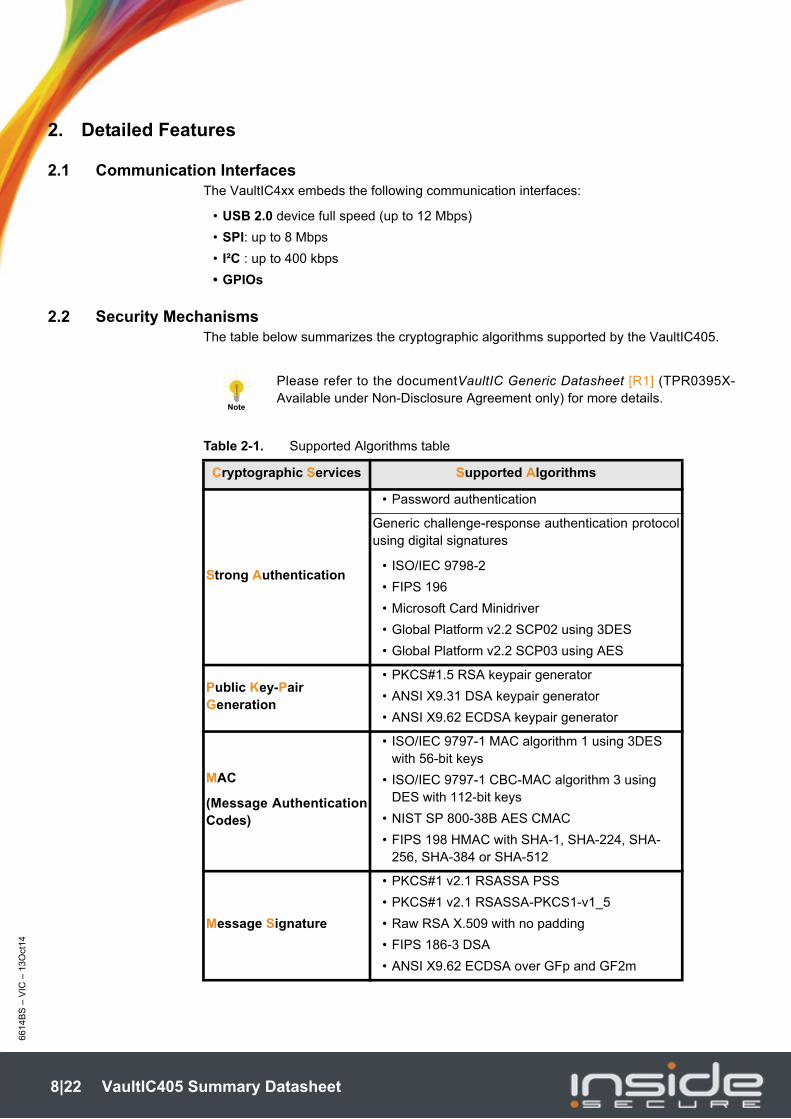
1.7 Software and Hardware ArchitectureThe VaultIC405 software architecture is as shown on the diagram below.
Figure 1-3. Software and Hardware Architecture
VaultIC405 Hardware
HardwareSecurity
PowerManagement
Device
SPI / I2C / USB
RAM
EEPROM
SPII2CUSB2.0
RISCCPU
PublicKey
CryptoEngine
AESTDES
RNG
Crypto Library(RSA, TDES, AES...)
Memory Management
Communication Stack(USB, I2C, SPI)
CryptoServices
(MAC, Signature...)
ApplicationManagement
& Storage
(File System)
AdministrationServices
(Key Management)
Security Domain(Security Policies, Access Controls, Role Management)
Application Interface
GPIOs
7|22 VaultIC405 Summary Datasheet
66
14B
S –
VIC
– 1
3O
ct1
4
2. Detailed Features
2.1 Communication InterfacesThe VaultIC4xx embeds the following communication interfaces:
• USB 2.0 device full speed (up to 12 Mbps)
• SPI: up to 8 Mbps
• I²C : up to 400 kbps
• GPIOs
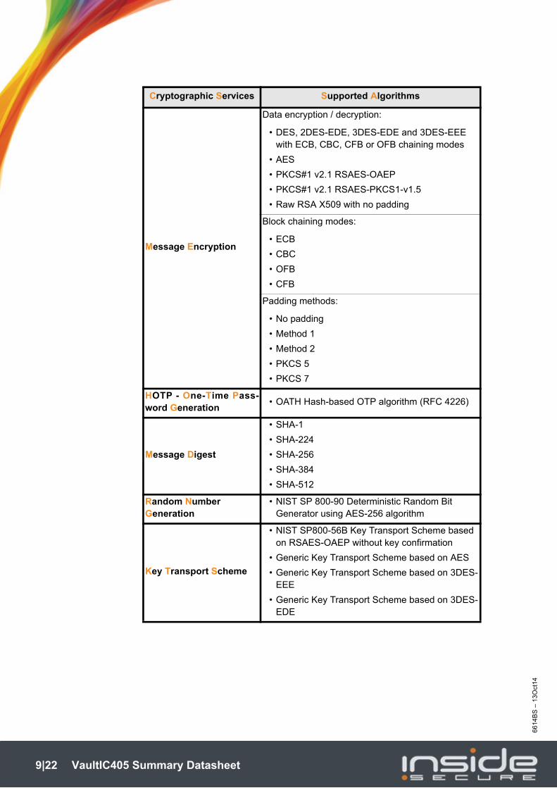
2.2 Security MechanismsThe table below summarizes the cryptographic algorithms supported by the VaultIC405.
Table 2-1. Supported Algorithms table
NoteNote
Please refer to the documentVaultIC Generic Datasheet [R1] (TPR0395X-Available under Non-Disclosure Agreement only) for more details.
Cryptographic Services Supported Algorithms
Strong Authentication
• Password authentication
Generic challenge-response authentication protocolusing digital signatures
• ISO/IEC 9798-2
• FIPS 196
• Microsoft Card Minidriver
• Global Platform v2.2 SCP02 using 3DES
• Global Platform v2.2 SCP03 using AES
Public Key-Pair Generation
• PKCS#1.5 RSA keypair generator
• ANSI X9.31 DSA keypair generator
• ANSI X9.62 ECDSA keypair generator
MAC
(Message AuthenticationCodes)
• ISO/IEC 9797-1 MAC algorithm 1 using 3DES with 56-bit keys
• ISO/IEC 9797-1 CBC-MAC algorithm 3 using DES with 112-bit keys
• NIST SP 800-38B AES CMAC
• FIPS 198 HMAC with SHA-1, SHA-224, SHA-256, SHA-384 or SHA-512
Message Signature
• PKCS#1 v2.1 RSASSA PSS
• PKCS#1 v2.1 RSASSA-PKCS1-v1_5
• Raw RSA X.509 with no padding
• FIPS 186-3 DSA
• ANSI X9.62 ECDSA over GFp and GF2m
8|22 VaultIC405 Summary Datasheet
66
14B
S –
13O
ct14
Message Encryption
Data encryption / decryption:
• DES, 2DES-EDE, 3DES-EDE and 3DES-EEE with ECB, CBC, CFB or OFB chaining modes
• AES
• PKCS#1 v2.1 RSAES-OAEP
• PKCS#1 v2.1 RSAES-PKCS1-v1.5
• Raw RSA X509 with no padding
Block chaining modes:
• ECB
• CBC
• OFB
• CFB
Padding methods:
• No padding
• Method 1
• Method 2
• PKCS 5
• PKCS 7
HOTP - One-Time Pass-word Generation
• OATH Hash-based OTP algorithm (RFC 4226)
Message Digest
• SHA-1
• SHA-224
• SHA-256
• SHA-384
• SHA-512
Random Number Generation
• NIST SP 800-90 Deterministic Random Bit Generator using AES-256 algorithm
Key Transport Scheme
• NIST SP800-56B Key Transport Scheme based on RSAES-OAEP without key confirmation
• Generic Key Transport Scheme based on AES
• Generic Key Transport Scheme based on 3DES-EEE
• Generic Key Transport Scheme based on 3DES-EDE
Cryptographic Services Supported Algorithms
9|22 VaultIC405 Summary Datasheet
66
14B
S –
VIC
– 1
3O
ct1
4
3. Product Characteristics
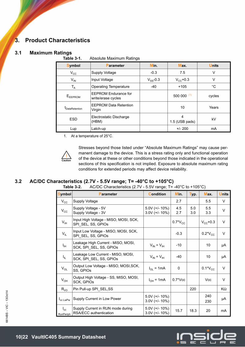
3.1 Maximum RatingsTable 3-1. Absolute Maximum Ratings
3.2 AC/DC Characteristics (2.7V - 5.5V range; T= -40°C to +105°C)Table 3-2. AC/DC Characteristics (2.7V - 5.5V range; T= -40°C to +105°C)
Symbol Parameter Min. Max. Units
VCC Supply Voltage -0.3 7.5 V
VIN Input Voltage VSS-0.3 VCC+0.3 V
TA Operating Temperature -40 +105 °C
EEEPROMEEPROM Endurance for write/erase cycles
500 000 (1) cycles
tDataRetentionEEPROM Data Retention Virgin
10 Years
ESDElectrostatic Discharge (HBM)
4 1.5 (USB pads)
kV
Lup Latch-up +/- 200 mA
1. At a temperature of 25°C.
Caution
!
Stresses beyond those listed under “Absolute Maximum Ratings” may cause per-manent damage to the device. This is a stress rating only and functional operationof the device at these or other conditions beyond those indicated in the operationalsections of this specification is not implied. Exposure to absolute maximum ratingconditions for extended periods may affect device reliability.
Symbol Parameter Condition Min. Typ. Max. Units
VCC Supply Voltage 2.7 5.5 V
VCCSupply Voltage - 5VSupply Voltage - 3V
5.0V (+/- 10%)3.0V (+/- 10%)
4.52.7
5.03.0
5.53.3
V
VIHInput High Voltage - MISO, MOSI, SCK, SPI_SEL, SS, GPIOs
0.7*VCC VCC+0.3 V
VILInput Low Voltage - MISO, MOSI, SCK, SPI_SEL, SS, GPIOs
-0.3 0.2*VCC V
IIHLeakage High Current - MISO, MOSI, SCK, SPI_SEL, SS, GPIOs
VIN = VIH -10 10 µA
IILLeakage Low Current - MISO, MOSI, SCK, SPI_SEL, SS, GPIOs
VIN = VIH -40 10 µA
VOLOutput Low Voltage - MISO, MOSI,SCK, SS, GPIOs
IOL = 1mA 0 0.1*VCC V
VOHOutput High Voltage - SS, MISO, MOSI, SCK, GPIOs
IOH = 1mA 0.7*Vcc Vcc V
RI/O Pin Pull-up SPI_SEL,SS 220 KΩ
Icc LwPw Supply Current in Low Power5.0V (+/- 10%)3.0V (+/- 10%)
240
230µA
Icc
RunPeriph
Supply Current in RUN mode during RSA/ECC authentication
5.0V (+/- 10%)3.0V (+/- 10%)
15.7 18.3 20 mA
10|22 VaultIC405 Summary Datasheet
66
14B
S –
13O
ct14
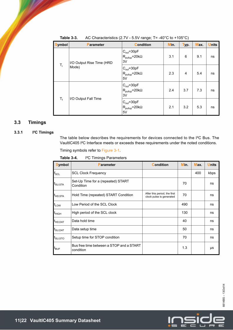
Table 3-3. AC Characteristics (2.7V - 5.5V range; T= -40°C to +105°C)
3.3 Timings
3.3.1 I²C Timings
The table below describes the requirements for devices connected to the I²C Bus. TheVaultIC405 I²C Interface meets or exceeds these requirements under the noted conditions.
Timing symbols refer to Figure 3-1.
Table 3-4. I²C Timings Parameters
Symbol Parameter Condition Min. Typ. Max. Units
TrI/O Output Rise Time (HRD Mode)
Cout=30pF
Rpullup=20kΩ3V
3.1 6 9.1 ns
Cout=30pF
Rpullup=20kΩ5V
2.3 4 5.4 ns
Tf I/O Output Fall Time
Cout=30pF
Rpullup=20kΩ3V
2.4 3.7 7.3 ns
Cout=30pF
Rpullup=20kΩ5V
2.1 3.2 5.3 ns
Symbol Parameter Condition Min. Max. Units
fSCL SCL Clock Frequency 400 kbps
tSU;STASet-Up Time for a (repeated) START Condition
70 ns
tHD;STA Hold Time (repeated) START Condition After this period, the first clock pulse is generated 70 ns
tLOW Low Period of the SCL Clock 490 ns
tHIGH High period of the SCL clock 130 ns
tHD;DAT Data hold time 40 ns
tSU;DAT Data setup time 50 ns
tSU;STO Setup time for STOP condition 70 ns
tBUFBus free time between a STOP and a START condition
1.3 µs
11|22 VaultIC405 Summary Datasheet
66
14B
S –
VIC
– 1
3O
ct1
4
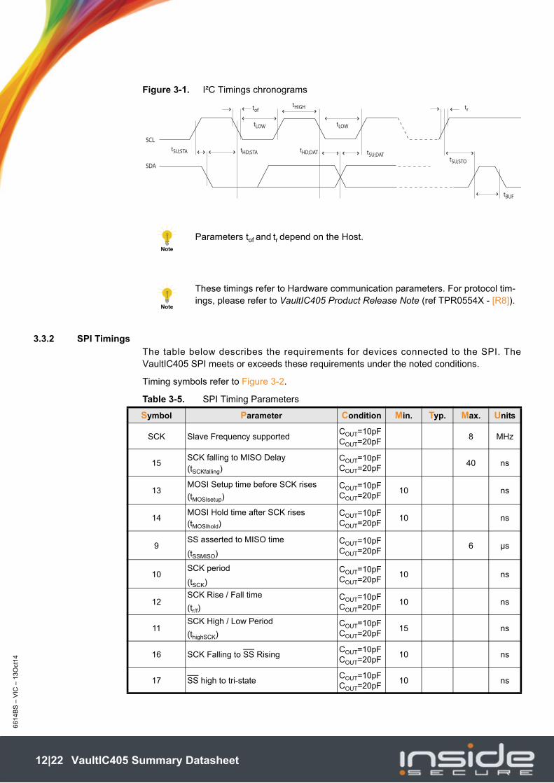
Figure 3-1. I²C Timings chronograms
3.3.2 SPI Timings
The table below describes the requirements for devices connected to the SPI. TheVaultIC405 SPI meets or exceeds these requirements under the noted conditions.
Timing symbols refer to Figure 3-2.
Table 3-5. SPI Timing Parameters
NoteNote
Parameters tof and tr depend on the Host.
NoteNote
These timings refer to Hardware communication parameters. For protocol tim-ings, please refer to VaultIC405 Product Release Note (ref TPR0554X - [R8]).
tSU;STA
tLOW
tHIGH
tLOW
tof
tHD;STA tHD;DAT tSU;DATtSU;STO
tBUF
SCL
SDA
tr
Symbol Parameter Condition Min. Typ. Max. Units
SCK Slave Frequency supportedCOUT=10pFCOUT=20pF
8 MHz
15SCK falling to MISO Delay (tSCKfalling)
COUT=10pFCOUT=20pF
40 ns
13MOSI Setup time before SCK rises
(tMOSIsetup)COUT=10pFCOUT=20pF
10 ns
14MOSI Hold time after SCK rises(tMOSIhold)
COUT=10pFCOUT=20pF
10 ns
9SS asserted to MISO time
(tSSMISO)
COUT=10pFCOUT=20pF
6 µs
10SCK period
(tSCK)
COUT=10pFCOUT=20pF
10 ns
12SCK Rise / Fall time
(tr/f)COUT=10pFCOUT=20pF
10 ns
11SCK High / Low Period
(thighSCK)COUT=10pFCOUT=20pF
15 ns
16 SCK Falling to SS RisingCOUT=10pFCOUT=20pF
10 ns
17 SS high to tri-stateCOUT=10pFCOUT=20pF
10 ns
12|22 VaultIC405 Summary Datasheet

66
14B
S –
13O
ct14
Figure 3-2. SPI Timings chronograms
NoteNote
These timings refer to Hardware communication parameters. For protocol timings,please refer to VaultIC405 Product Release Note (ref TPR0554X - [R8]).
MISO(Data Output)
MOSI(Data Input)
SCK(CPOL = 0)
SS
MSB LSB
LSBMSB
...
...
10
11 11
1213 14
1715
9
X
16
13|22 VaultIC405 Summary Datasheet

66
14B
S –
VIC
– 1
3O
ct1
4
3.4 Connections for Typical Application
Figure 3-3. VaultIC405 connections for USB typical application
Figure 3-4. VaultIC405 connections for I²C typical application
Figure 3-5. VaultIC405 connections for SPI typical application
USB
CONNECTOR
AT90SC6464C-USBVaultIC405
USB_XOUT
USB_XIN
USB_DM
USB_DP
VBUS
GND
48 MHz
RESONATOR
C1 C2
C1
VCC
C2
R1
RST
SCLSDA / SPI_SEL
SCLSDA
RESET
VCCVCC
VaultIC405HOST
GND
R2
VCC
A0..A4 Address Selection
C1
VCC
C2
RSTRESET
VCCVCC
VaultIC405
HOST
GND
SPI_SEL
MISO
MOSI
SCK
MOSI
MISO
SCKSSSS
14|22 VaultIC405 Summary Datasheet
66
14B
S –
13O
ct14
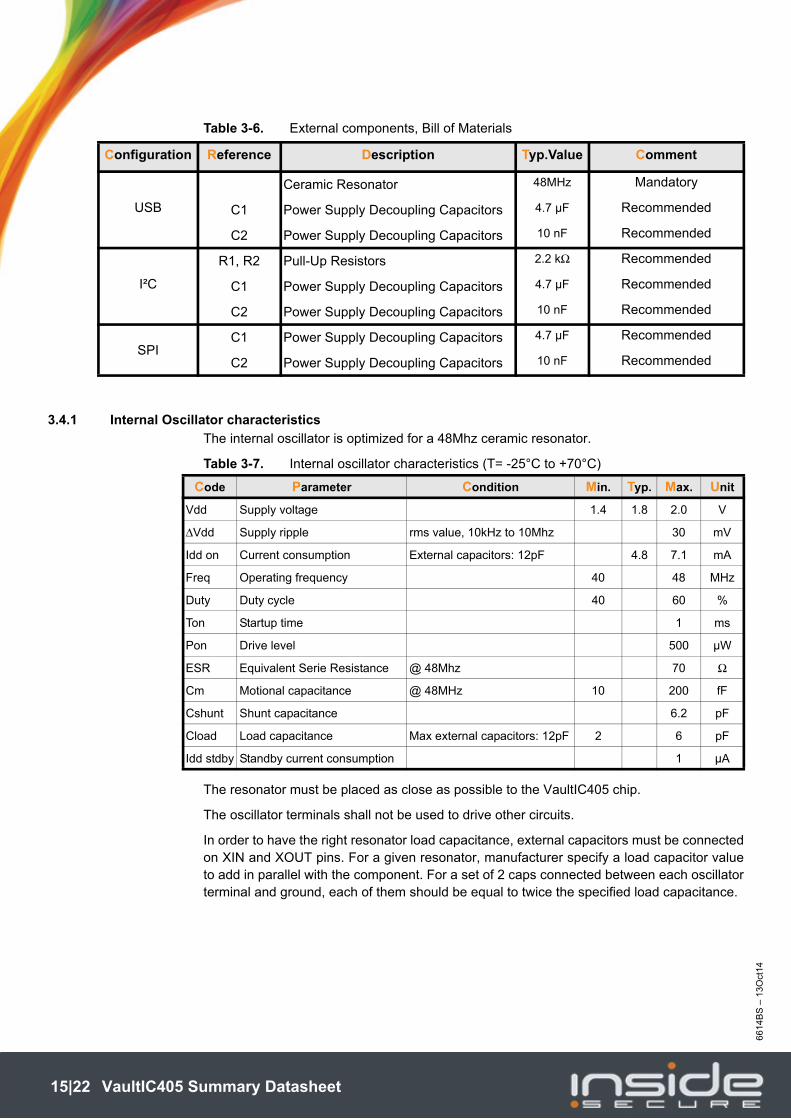
Table 3-6. External components, Bill of Materials
3.4.1 Internal Oscillator characteristics
The internal oscillator is optimized for a 48Mhz ceramic resonator.
Table 3-7. Internal oscillator characteristics (T= -25°C to +70°C)
The resonator must be placed as close as possible to the VaultIC405 chip.
The oscillator terminals shall not be used to drive other circuits.
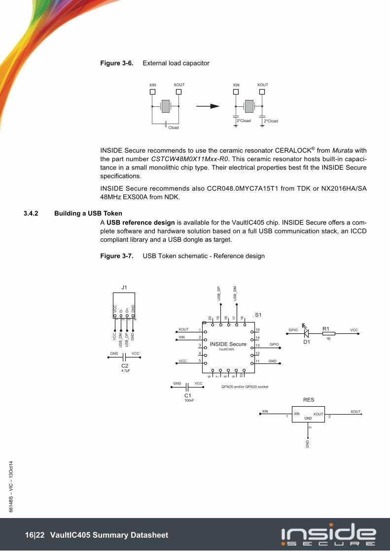
In order to have the right resonator load capacitance, external capacitors must be connectedon XIN and XOUT pins. For a given resonator, manufacturer specify a load capacitor valueto add in parallel with the component. For a set of 2 caps connected between each oscillatorterminal and ground, each of them should be equal to twice the specified load capacitance.
Configuration Reference Description Typ.Value Comment
USB
Ceramic Resonator 48MHz Mandatory
C1 Power Supply Decoupling Capacitors 4.7 μF Recommended
C2 Power Supply Decoupling Capacitors 10 nF Recommended
I²C
R1, R2 Pull-Up Resistors 2.2 kΩ Recommended
C1 Power Supply Decoupling Capacitors 4.7 μF Recommended
C2 Power Supply Decoupling Capacitors 10 nF Recommended
SPIC1 Power Supply Decoupling Capacitors 4.7 μF Recommended
C2 Power Supply Decoupling Capacitors 10 nF Recommended
Code Parameter Condition Min. Typ. Max. Unit
Vdd Supply voltage 1.4 1.8 2.0 V
ΔVdd Supply ripple rms value, 10kHz to 10Mhz 30 mV
Idd on Current consumption External capacitors: 12pF 4.8 7.1 mA
Freq Operating frequency 40 48 MHz
Duty Duty cycle 40 60 %
Ton Startup time 1 ms
Pon Drive level 500 µW
ESR Equivalent Serie Resistance @ 48Mhz 70 Ω
Cm Motional capacitance @ 48MHz 10 200 fF
Cshunt Shunt capacitance 6.2 pF
Cload Load capacitance Max external capacitors: 12pF 2 6 pF
Idd stdby Standby current consumption 1 µA
15|22 VaultIC405 Summary Datasheet
66
14B
S –
VIC
– 1
3O
ct1
4
Figure 3-6. External load capacitor
INSIDE Secure recommends to use the ceramic resonator CERALOCK® from Murata withthe part number CSTCW48M0X11Mxx-R0. This ceramic resonator hosts built-in capaci-tance in a small monolithic chip type. Their electrical properties best fit the INSIDE Securespecifications.
INSIDE Secure recommends also CCR048.0MYC7A15T1 from TDK or NX2016HA/SA48MHz EXS00A from NDK.
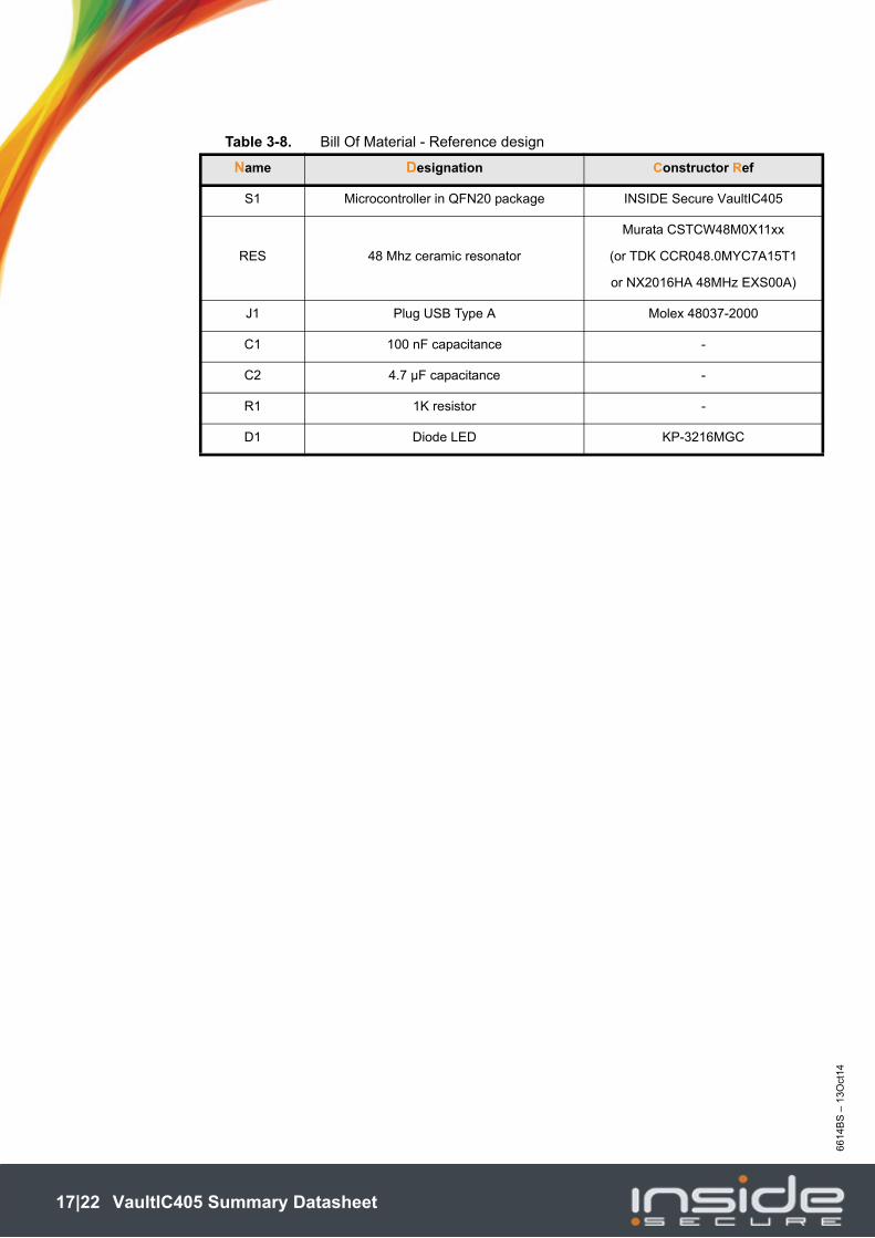
3.4.2 Building a USB Token
A USB reference design is available for the VaultIC405 chip. INSIDE Secure offers a com-plete software and hardware solution based on a full USB communication stack, an ICCDcompliant library and a USB dongle as target.
Figure 3-7. USB Token schematic - Reference design
XIN XOUT
Cload
XIN XOUT
2*Cload2*Cload
VC
C
US
B_
DM
GN
D
3
16
10
17
18
5
9
19
20
8
15
14
4
7
13
2
12
6
11
S1
QFN20 and/or QFN20 socket
C1100nF
R1
1KD1
GN
D4
D+
3
D-
2
VC
C1
J1
GND
3
XOUT2
XIN1
RES
INSIDE SecureVaultIC405
1
US
B_
DP
US
B_
DM
US
B_
DP
XOUT
XOUT
XIN
VCC GND
GPIO
XIN
GN
D
GPIO VCC
GND VCC
C24.7μF
GND VCC
16|22 VaultIC405 Summary Datasheet
66
14B
S –
13O
ct14
Table 3-8. Bill Of Material - Reference design
Name Designation Constructor Ref
S1 Microcontroller in QFN20 package INSIDE Secure VaultIC405
RES 48 Mhz ceramic resonator
Murata CSTCW48M0X11xx
(or TDK CCR048.0MYC7A15T1
or NX2016HA 48MHz EXS00A)
J1 Plug USB Type A Molex 48037-2000
C1 100 nF capacitance -
C2 4.7 µF capacitance -
R1 1K resistor -
D1 Diode LED KP-3216MGC
17|22 VaultIC405 Summary Datasheet
66
14B
S –
VIC
– 1
3O
ct1
4
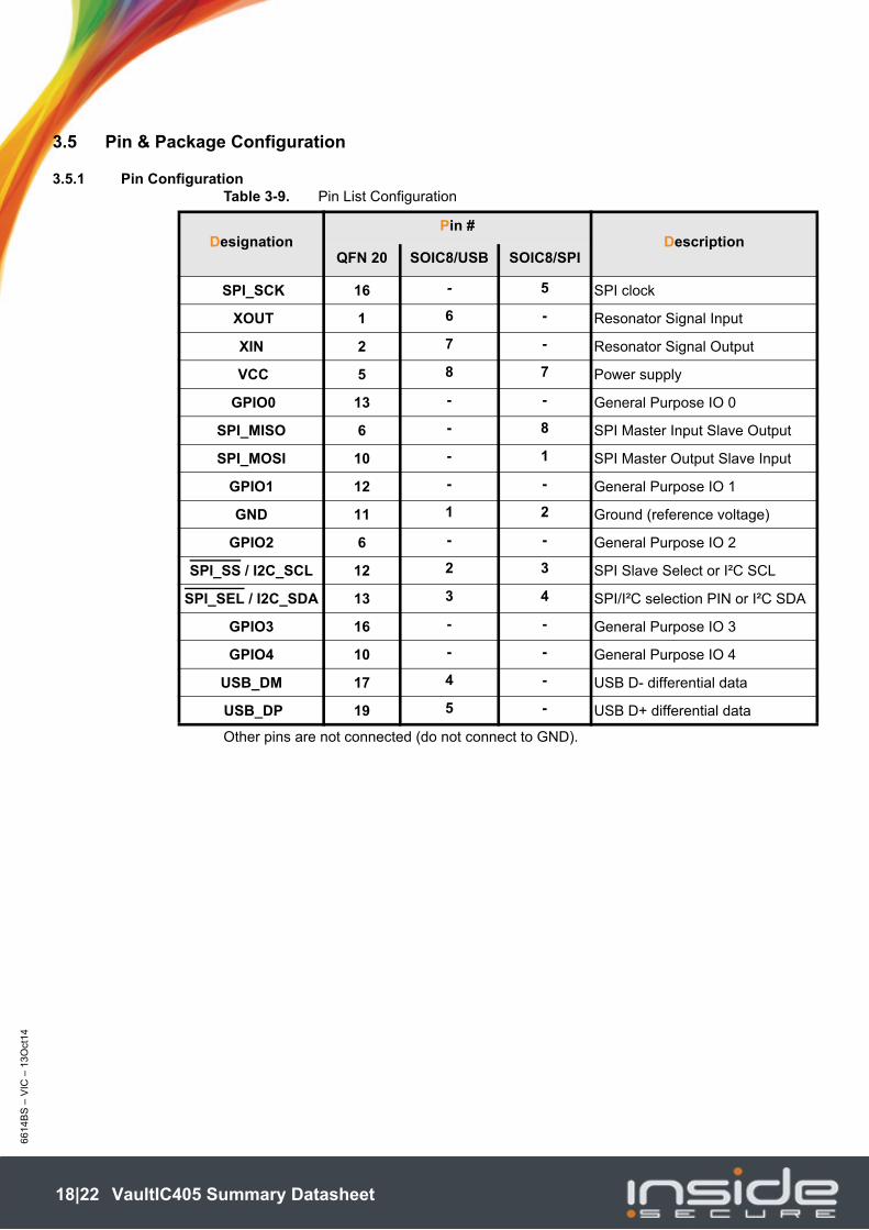
3.5 Pin & Package Configuration
3.5.1 Pin ConfigurationTable 3-9. Pin List Configuration
Other pins are not connected (do not connect to GND).
DesignationPin #
DescriptionQFN 20 SOIC8/USB SOIC8/SPI
SPI_SCK 16 - 5 SPI clock
XOUT 1 6 - Resonator Signal Input
XIN 2 7 - Resonator Signal Output
VCC 5 8 7 Power supply
GPIO0 13 - - General Purpose IO 0
SPI_MISO 6 - 8 SPI Master Input Slave Output
SPI_MOSI 10 - 1 SPI Master Output Slave Input
GPIO1 12 - - General Purpose IO 1
GND 11 1 2 Ground (reference voltage)
GPIO2 6 - - General Purpose IO 2
SPI_SS / I2C_SCL 12 2 3 SPI Slave Select or I²C SCL
SPI_SEL / I2C_SDA 13 3 4 SPI/I²C selection PIN or I²C SDA
GPIO3 16 - - General Purpose IO 3
GPIO4 10 - - General Purpose IO 4
USB_DM 17 4 - USB D- differential data
USB_DP 19 5 - USB D+ differential data
18|22 VaultIC405 Summary Datasheet

66
14B
S –
13O
ct14
3.5.2 Pinouts for packages QFN20 and SOIC8
Figure 3-8. Pinout VaultIC405 - Package QFN20
Note: The exposed pad is connected to GND pin internally. So it is recommended to connect it to GND.
Figure 3-9. Pinout VaultIC405 - Package SOIC8 - USB and I²C configurations
Figure 3-10. Pinout VaultIC405 - Package SOIC8 - SPI and I²C configurations
2
3
1
4
5
15
14
13
12
11
6 7 98 10
20
19
18
17
16
VAULTIC405
QFN20
GPIO0 / I2C_SDA / SPI_SEL
GPIO1 / I2C_SCL / SPI_SS
GND
XOUT
XIN
GP
IO2 /
SP
I_M
ISO
GP
IO4 /
SP
I_M
OS
I
US
B_D
+
US
B_D
-
GP
IO3 / S
PI_
SC
K
VCC
Index Corner
VaultIC405SOIC8 / USB
INDEX CORNER
GND
GPIO1/ I2C_SCL
USB_DM
1
2
3
4
8
7
6
5
VBUS
USB_XIN
USB_XOUT
USB_DP
GPIO0 / I2C_SDA
VaultIC405SOIC8 / SPI / I²C
INDEX CORNER
SPI_MOSI
GND
1
2
3
4
8
7
6
5
SPI_MISO
VCC
SPI_SCK
I2C_SCL / SPI_SS
I2C_SDA / SPI_SEL
19|22 VaultIC405 Summary Datasheet
66
14B
S –
VIC
– 1
3O
ct1
4
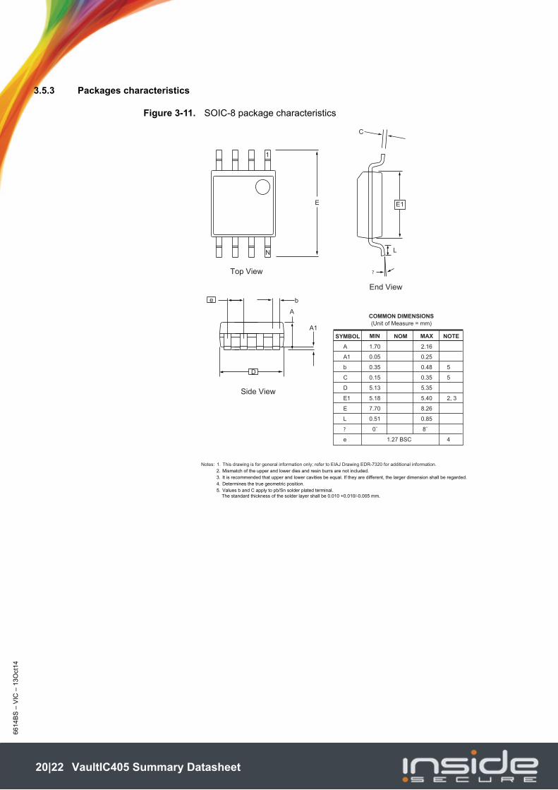
3.5.3 Packages characteristics
Figure 3-11. SOIC-8 package characteristics
COMMON DIMENSIONS(Unit of Measure = mm)
SYMBOL MIN NOM MAX NOTE
Notes: 1. This drawing is for general information only; refer to EIAJ Drawing EDR-7320 for additional information.
2. Mismatch of the upper and lower dies and resin burrs are not included.
3. It is recommended that upper and lower cavities be equal. If they are different, the larger dimension shall be regarded.
4. Determines the true geometric position.
5. Values b and C apply to pb/Sn solder plated terminal.
The standard thickness of the solder layer shall be 0.010 +0.010/-0.005 mm.
A 1.70 2.16
A1 0.05 0.25
b 0.35 0.48 5
C 0.15 0.35 5
D 5.13 5.35
E1 5.18 5.40 2, 3
E 7.70 8.26
L 0.51 0.85
? 0˚ 8˚
e 1.27 BSC 4
End View
Side View
e b
A
A1
D
E
N
1
C
E1
?
L
Top View
20|22 VaultIC405 Summary Datasheet

66
14B
S –
13O
ct14
Figure 3-12. QFN-20 package characteristics
21|22 VaultIC405 Summary Datasheet
66
14B
S –
13O
ct14
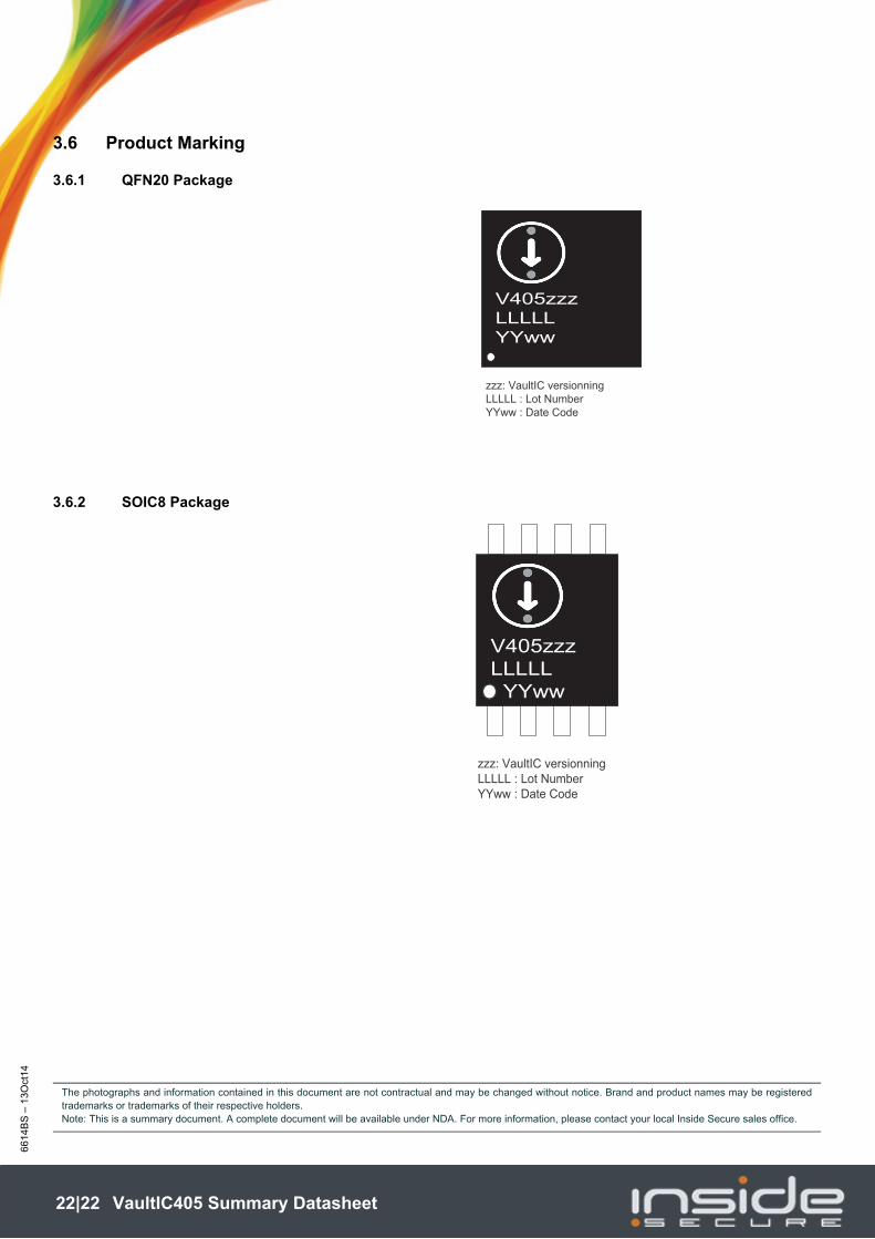
3.6 Product Marking
3.6.1 QFN20 Package
3.6.2 SOIC8 Package
V405zzz
LLLLL
YYww
zzz: VaultIC versionning
LLLLL : Lot Number
YYww : Date Code
V405zzz
LLLLL
YYww
zzz: VaultIC versionning
LLLLL : Lot Number
YYww : Date Code
The photographs and information contained in this document are not contractual and may be changed without notice. Brand and product names may be registeredtrademarks or trademarks of their respective holders.Note: This is a summary document. A complete document will be available under NDA. For more information, please contact your local Inside Secure sales office.
22|22 VaultIC405 Summary Datasheet