vav zone controllers - sigler...
TRANSCRIPT
VVAAVV ZZoonnee CCoonnttrroolllleerrss
IInnssttaallllaattiioonn aanndd SSttaarrtt--uupp GGuuiiddee
CARRIER CORPORATION ©2011 A member of the United Technologies Corporation family · Stock symbol UTX · Catalog No. 11-808-432-01 · 6/21/2011

VAV Zone Controllers i
Table of Contents Introduction .................................................................................................................................................................. 1
What are VAV Zone Controllers? ........................................................................................................................ 1 Linkage ................................................................................................................................................................... 4 Specifications ........................................................................................................................................................ 5 Safety Considerations .......................................................................................................................................... 7
Installation ................................................................................................................................................................... 8 Field-supplied hardware ...................................................................................................................................... 8 Mounting the VAV Zone Controller ..................................................................................................................... 9
To mount the controller ........................................................................................................................ 9 Wiring the VAV Zone Controller for power ..................................................................................................... 11
To wire the controller for power .......................................................................................................... 11 To address the VAV Zone Controller ............................................................................................................... 12 Wiring the VAV Zone Controller to the MS/TP network ............................................................................... 12
Wiring specifications ........................................................................................................................... 13 To wire the controller to the network ................................................................................................. 13
Wiring sensors to inputs ................................................................................................................................... 14 Wiring an SPT sensor .......................................................................................................................... 14
Rnet wiring specifications ........................................................................................................ 15 To wire the SPT sensor to the controller ................................................................................. 16
Wiring a T55 space temperature sensor ........................................................................................... 17 Wiring specifications ................................................................................................................ 17 To wire the T55 sensor to the controller ................................................................................. 17
Wiring a Supply Air Temperature sensor ............................................................................................ 18 Wiring specifications ................................................................................................................ 18 To wire the SAT sensor to the controller ................................................................................. 18
Wiring a CO2 sensor ............................................................................................................................ 18 Wiring specifications ................................................................................................................ 19 To wire the CO2 sensor to the controller ................................................................................ 19
Wiring a Relative Humidity sensor ..................................................................................................... 21 Wiring specifications ................................................................................................................ 21 To wire the RH sensor to the controller................................................................................... 21
Wiring a remote occupancy sensor .................................................................................................... 22 Wiring specifications ................................................................................................................ 22
Wiring equipment to outputs ........................................................................................................................... 22 Wiring specifications ........................................................................................................................... 23 Balancing the system using i-Vu/Field Assistant .............................................................................. 23
Step 1: Prepare for balancing ................................................................................................. 23 Step 2: Balance each zone ..................................................................................................... 24
Balancing the system using Test & Balance tool .............................................................................. 24 To calibrate VAV Zone airflow .................................................................................................. 25 Step 3: Upload calibration values to i-Vu/Field Assistant ..................................................... 26 Step 4: Run a report in VAV Zone Controller (Optional) ........................................................ 26
Wiring diagram legend ........................................................................................................................ 27 No heat - Single duct or fan box application ...................................................................................... 27 2-position hot water/steam heat - Single duct .................................................................................. 28 Modulating hot water/steam (ducted or baseboard) - Single duct application ............................... 28 Combination heat (ducted electric heat with modulating baseboard heat) - Single duct application.............................................................................................................................................................. 29 Electric heat (ducted or baseboard) - Single duct application .......................................................... 29 2-position hot water/steam (ducted or baseboard) - Fan box application ...................................... 30 Modulating hot water (ducted or baseboard) - Fan box application ................................................ 30
Table of Contents
ii VAV Zone Controllers
Combination heat (ducted electric heat with modulating baseboard heat) - Fan box application. 31 2-stage electric heat (ducted or baseboard) - Fan box application .................................................. 31 Wiring a field-supplied high-torque actuator to the analog output ................................................... 32
Start-up ....................................................................................................................................................................... 33 Configuring the VAV Zone Controller's properties ........................................................................................ 33
Unit Configuration properties ............................................................................................................. 34 Setpoint properties.............................................................................................................................. 35 Service Configuration properties ........................................................................................................ 37 Linkage properties .............................................................................................................................. 39
Performing system checkout ........................................................................................................................... 40 Commissioning the VAV Zone Controller ....................................................................................................... 41 Balancing the system ........................................................................................................................................ 41
Prepare for balancing.......................................................................................................................... 41 Sequence of operation .............................................................................................................................................. 42
Temperature sensors ........................................................................................................................................ 42 Zone airflow control ........................................................................................................................................... 42 Zone reheat control ........................................................................................................................................... 43 Demand control ventilation (DCV) and dehumidification using optional sensors ................................... 44 Occupancy ........................................................................................................................................................... 45 Alarms ................................................................................................................................................................. 46 Demand limiting ................................................................................................................................................ 47 Linkage ................................................................................................................................................................ 47 Air source mode determination....................................................................................................................... 50
Troubleshooting ......................................................................................................................................................... 51 LED's .................................................................................................................................................................... 51 Serial number ..................................................................................................................................................... 52 Replacing the VAV Zone Controller's battery ................................................................................................. 52
Compliance ................................................................................................................................................................ 53 FCC Compliance ................................................................................................................................................. 53 CE Compliance ................................................................................................................................................... 53 BACnet Compliance........................................................................................................................................... 53
Appendix A: VAV Zone Controller Points/Properties ............................................................................................. 54 Status................................................................................................................................................................... 54 Unit Configuration .............................................................................................................................................. 55 Setpoints ............................................................................................................................................................. 56 Alarm Configuration .......................................................................................................................................... 61 Service Configuration ........................................................................................................................................ 63 Maintenance ....................................................................................................................................................... 66 Alarms ................................................................................................................................................................. 68 Linkage ................................................................................................................................................................ 69 I/O Points ............................................................................................................................................................ 70
Appendix B: VVT terminal modes ............................................................................................................................. 73 Index ........................................................................................................................................................................... 75
VAV Zone Controllers 1
What are VAV Zone Controllers?
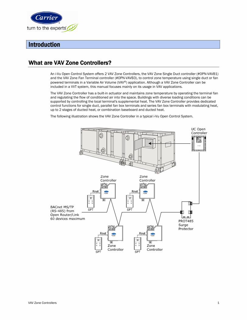
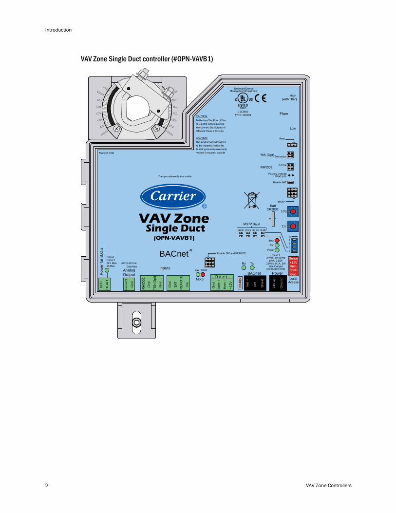
An i-Vu Open Control System offers 2 VAV Zone Controllers, the VAV Zone Single Duct controller (#OPN-VAVB1) and the VAV Zone Fan Terminal controller (#OPN-VAVB3), to control zone temperature using single duct or fan powered terminals in a Variable Air Volume (VAV®) application. Although a VAV Zone Controller can be included in a VVT system, this manual focuses mainly on its usage in VAV applications.
The VAV Zone Controller has a built-in actuator and maintains zone temperature by operating the terminal fan and regulating the flow of conditioned air into the space. Buildings with diverse loading conditions can be supported by controlling the local terminal's supplemental heat. The VAV Zone Controller provides dedicated control functions for single duct, parallel fan box terminals and series fan box terminals with modulating heat, up to 2 stages of ducted heat, or combination baseboard and ducted heat.
The following illustration shows the VAV Zone Controller in a typical i-Vu Open Control System.
VVT Zone(OPN-VVTZC)
VVT Zone(OPN-VVTZC)
VVT Zone(OPN-VVTZC)
VVT Zone(OPN-VVTZC)
MANUAL ON WARMER
Occupied
INFO COOLER
F
MANUAL ON WARMER
Occupied
INFO COOLER
F
MANUAL ON WARMER
Occupied
INFO COOLER
F
MANUAL ON WARMER
Occupied
INFO COOLER
F
UC Open
Introduction
Introduction
2 VAV Zone Controllers
VAV Zone Single Duct controller (#OPN-VAVB1)
01
345
2
789 6
01
345
2
789 6
HW
V/A
CT
Gnd
AnalogOutput
Gnd
T55
(Opt
)
RH
/CO
2G
nd
SAT
Gnd
REM
OTE
n/a
Gnd
Rne
t +
Rne
t -
+12V
R n e tBACnet Power
On4321
-+
BattCR2032 10's
1's
ThermistorT55 (Opt)
RH/CO2
Factory Defaults
Rnet
MSTP
Class 2Output
24V Max,1A Max
Conductors Only
Class 2
Use Copper26Vdc, 0.1A, 3W
14VA, 0.58A24Vac, 50-60 Hz
This product was designedCAUTION:
to be mounted inside thebuilding envelope.Warrantyvoided if mounted outside.
Interconnect the Outputs ofDifferent Class 2 Circuits.
To ReduceThe Risk of Fireor Electric Shock, Do Not
CAUTION:
BACnet ®AO: 0-10 Vdc
5mA Max
LocalAccess
Short pins
Enable SAT
Enable SAT and REMOTE
CW CCW
Motor
Error
Run
Power
0-5Vdc
Made in USA
InputsTxRx
MSTP Baud
76.8k38.4k19.2k9600
Damper release button inside
TYPE: 002101E143900
88FO
Enclosed EnergyManagement Equipment
R
Net
+
Net
-
Shie
ld
Gro
und
24V
acRnet+
Sense+12VRnet-
GndPow
er fo
r B.O
.sBU
S
HE
AT1
BT48
5
VAV ZoneSingle Duct
(OPN-VAVB1)
High
Low
Flow
(with filter)
VAV Zone Controllers 3
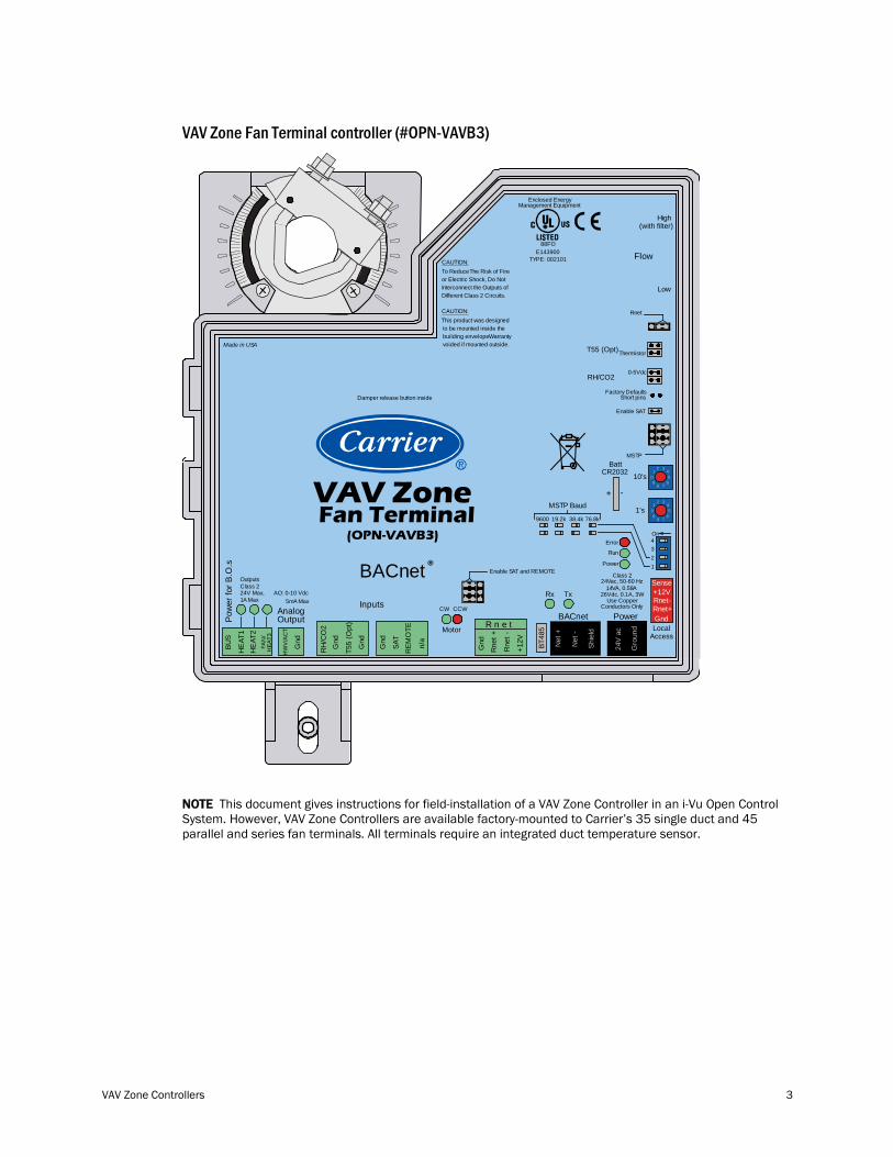
VAV Zone Fan Terminal controller (#OPN-VAVB3)
01
345
2
789 6
01
345
2
789 6
HW
V/A
CT
Gnd
AnalogOutput
Gnd
T55
(Opt
)
RH
/CO
2G
nd
SAT
Gnd
REM
OTE
n/a
Gnd
Rne
t +
Rne
t -
+12V
R n e tBACnet Power
On4321
-+
BattCR2032 10's
1's
ThermistorT55 (Opt)
RH/CO2
Factory Defaults
Rnet
MSTP
OutputsClass 224V Max,1A Max
Conductors Only
Class 2
Use Copper26Vdc, 0.1A, 3W
14VA, 0.58A24Vac, 50-60 Hz
This product was designedCAUTION:
to be mounted inside thebuilding envelope.Warrantyvoided if mounted outside.
Interconnect the Outputs ofDifferent Class 2 Circuits.
To ReduceThe Risk of Fireor Electric Shock, Do Not
CAUTION:
BACnet ®AO: 0-10 Vdc
5mA Max
LocalAccess
Short pins
Enable SAT
Enable SAT and REMOTE
CW CCW
Motor
Error
Run
Power
0-5Vdc
Made in USA
InputsTxRx
MSTP Baud
76.8k38.4k19.2k9600
Damper release button inside
TYPE: 002101E143900
88FO
Enclosed EnergyManagement Equipment
R
Net
+
Net
-
Shie
ld
Gro
und
24V
acRnet+
Sense+12VRnet-
Gnd
FAN
/
Pow
er fo
r B.O
.sBU
S
HE
AT1
HE
AT2
HEA
T3
BT48
5
VAV ZoneFan Terminal
(OPN-VAVB3)
High
Low
Flow
(with filter)
NOTE This document gives instructions for field-installation of a VAV Zone Controller in an i-Vu Open Control System. However, VAV Zone Controllers are available factory-mounted to Carrier’s 35 single duct and 45 parallel and series fan terminals. All terminals require an integrated duct temperature sensor.
Introduction
4 VAV Zone Controllers
Linkage
The i-Vu Open Control System uses linkage to exchange data between the zone terminals and their air source to form a coordinated HVAC system. The system's air source controller and zone controllers are linked so that their data exchange can be managed by one zone controller configured as the VAV Master.
A VAV Master can have a maximum of 63 slave zone controllers reporting to it. An MS/TP network is limited to a maximum of 60 controllers, but a VAV Master can have controllers from other networks as slaves.
A linked VAV system can be as simple as a single MS/TP network with a VAV Master and slaves, or it can be as complex as multiple MS/TP networks with VAV sub-masters and slaves on other networks. See the following examples.
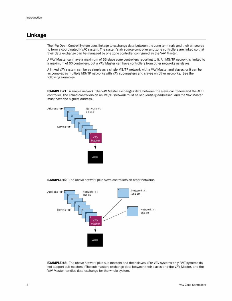
EXAMPLE #1: A simple network. The VAV Master exchanges data between the slave controllers and the AHU controller. The linked controllers on an MS/TP network must be sequentially addressed, and the VAV Master must have the highest address.
Address 1
2
3
4
5
6
7
8VAV
Master
Slaves
Network #:16116
AHU
EXAMPLE #2: The above network plus slave controllers on other networks.
Address 1
2
3
4
5
3
116
7
8VAV
Master
Slaves
Network #:16116
Network #:16119
Network #:16130
AHU
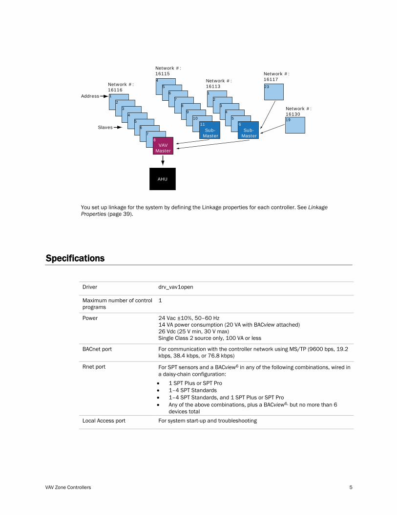
EXAMPLE #3: The above network plus sub-masters and their slaves. (For VAV systems only. VVT systems do not support sub-masters.) The sub-masters exchange data between their slaves and the VAV Master, and the VAV Master handles data exchange for the whole system.
VAV Zone Controllers 5
Address 1
2
3
4
5
23
19
6
7
8VAV
Master
4
5
6
7
8
9
10
11
Sub-Master
1
2
3
4
5
6
Sub-Master
Slaves
Network #:16116
Network #:16115
Network #:16113
Network #:16117
Network #:16130
AHU
You set up linkage for the system by defining the Linkage properties for each controller. See Linkage Properties (page 39).
Specifications
Driver drv_vav1open
Maximum number of control programs
1
Power 24 Vac ±10%, 50–60 Hz 14 VA power consumption (20 VA with BACview
BACnet port
attached) 26 Vdc (25 V min, 30 V max) Single Class 2 source only, 100 VA or less
For communication with the controller network using MS/TP (9600 bps, 19.2 kbps, 38.4 kbps, or 76.8 kbps)
Rnet port For SPT sensors and a BACview6
• 1 SPT Plus or SPT Pro
in any of the following combinations, wired in a daisy-chain configuration:
• 1–4 SPT Standards • 1–4 SPT Standards, and 1 SPT Plus or SPT Pro • Any of the above combinations, plus a BACview6,
Local Access port
but no more than 6 devices total
For system start-up and troubleshooting
Introduction
6 VAV Zone Controllers
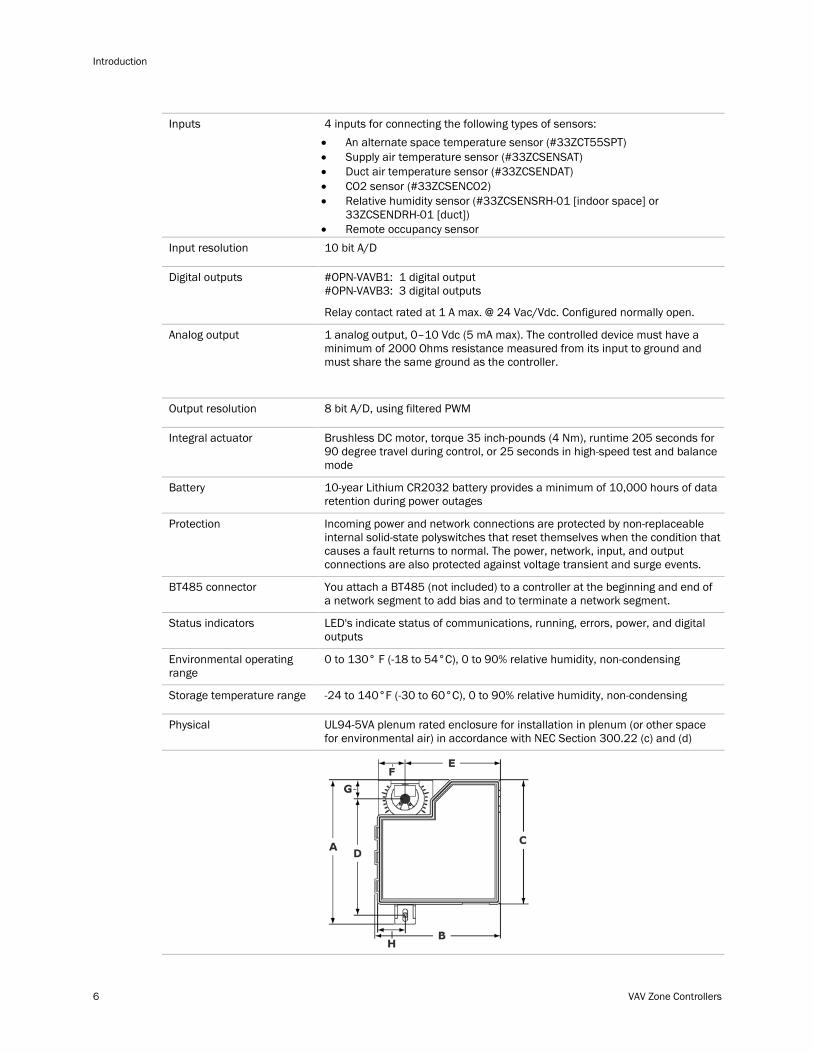
Inputs 4 inputs for connecting the following types of sensors: • An alternate space temperature sensor (#33ZCT55SPT) • Supply air temperature sensor (#33ZCSENSAT) • Duct air temperature sensor (#33ZCSENDAT) • CO2 sensor (#33ZCSENCO2) • Relative humidity sensor (#33ZCSENSRH-01 [indoor space] or
33ZCSENDRH-01 [duct]) • Remote occupancy sensor
Input resolution 10 bit A/D
Digital outputs #OPN-VAVB1: 1 digital output #OPN-VAVB3: 3 digital outputs
Relay contact rated at 1 A max. @ 24 Vac/Vdc. Configured normally open.
Analog output 1 analog output, 0–10 Vdc (5 mA max). The controlled device must have a minimum of 2000 Ohms resistance measured from its input to ground and must share the same ground as the controller.
Output resolution 8 bit A/D, using filtered PWM
Integral actuator Brushless DC motor, torque 35 inch-pounds (4 Nm), runtime 205 seconds for 90 degree travel during control, or 25 seconds in high-speed test and balance mode
Battery 10-year Lithium CR2032 battery provides a minimum of 10,000 hours of data retention during power outages
Protection Incoming power and network connections are protected by non-replaceable internal solid-state polyswitches that reset themselves when the condition that causes a fault returns to normal. The power, network, input, and output connections are also protected against voltage transient and surge events.
BT485 connector You attach a BT485 (not included) to a controller at the beginning and end of a network segment to add bias and to terminate a network segment.
Status indicators LED's indicate status of communications, running, errors, power, and digital outputs
Environmental operating range
0 to 130° F (-18 to 54°C), 0 to 90% relative humidity, non-condensing
Storage temperature range -24 to 140°F (-30 to 60°C), 0 to 90% relative humidity, non-condensing
Physical UL94-5VA plenum rated enclosure for installation in plenum (or other space for environmental air) in accordance with NEC Section 300.22 (c) and (d)
VAV Zone Controllers 7
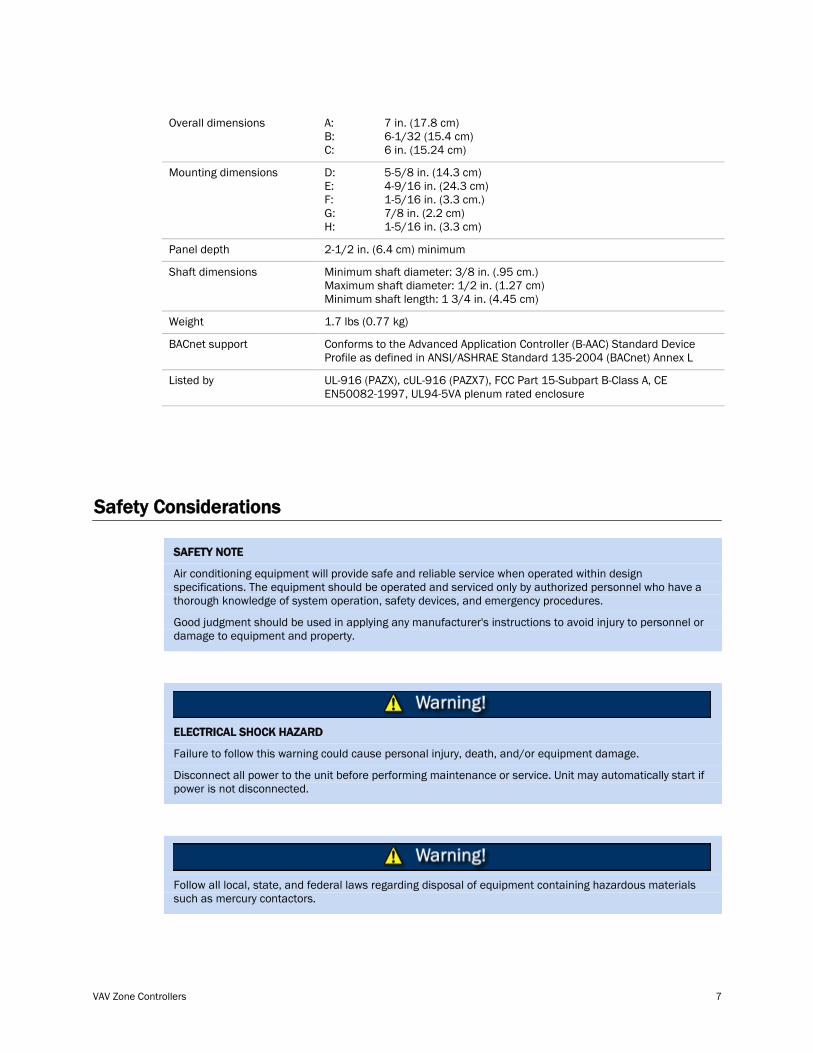
Overall dimensions A: B: C:
7 in. (17.8 cm) 6-1/32 (15.4 cm) 6 in. (15.24 cm)
Mounting dimensions D: E: F: G: H:
5-5/8 in. (14.3 cm) 4-9/16 in. (24.3 cm) 1-5/16 in. (3.3 cm.) 7/8 in. (2.2 cm) 1-5/16 in. (3.3 cm)
Panel depth 2-1/2 in. (6.4 cm) minimum
Shaft dimensions Minimum shaft diameter: 3/8 in. (.95 cm.) Maximum shaft diameter: 1/2 in. (1.27 cm) Minimum shaft length: 1 3/4 in. (4.45 cm)
Weight 1.7 lbs (0.77 kg)
BACnet support Conforms to the Advanced Application Controller (B-AAC) Standard Device Profile as defined in ANSI/ASHRAE Standard 135-2004 (BACnet) Annex L
Listed by UL-916 (PAZX), cUL-916 (PAZX7), FCC Part 15-Subpart B-Class A, CE EN50082-1997, UL94-5VA plenum rated enclosure
Safety Considerations
Air conditioning equipment will provide safe and reliable service when operated within design specifications. The equipment should be operated and serviced only by authorized personnel who have a thorough knowledge of system operation, safety devices, and emergency procedures.
SAFETY NOTE
Good judgment should be used in applying any manufacturer's instructions to avoid injury to personnel or damage to equipment and property.
Failure to follow this warning could cause personal injury, death, and/or equipment damage.
ELECTRICAL SHOCK HAZARD
Disconnect all power to the unit before performing maintenance or service. Unit may automatically start if power is not disconnected.
Follow all local, state, and federal laws regarding disposal of equipment containing hazardous materials such as mercury contactors.
Installation
8 VAV Zone Controllers
To install the VAV Zone Controller:
1 Mount the controller to the VAV terminal. (page 9)
2 Wire the controller for power. (page 11)
3 Set the controller's address. (page 12)
4 Wire the controller to the MS/TP network. (page 12)
5 Wire sensor(s) to the controller. (page 14)
6 Wire equipment to the controller's outputs. (page 22)
Field-supplied hardware
Each zone controller installation requires the following field-supplied components: • zone terminal unit • round or rectangular mounting bracket • space temperature sensor • supply air temperature sensor • 4x2-in. electrical box • transformer— 24 Vac, 40 VA • two no. 10 x 1/2-in. sheet metal screws (to secure SAT sensor to duct) • two no. 6-32 x 5/8-in. screws (to mount space temperature sensor base to electrical box) • wiring • bushings (required when mounting SAT sensor in a duct 6-in. or less in diameter)
Optional: • contactors (if required for fan or electric heat) • indoor air quality sensor • relative humidity sensor • 2 screws and 2 hollow wall anchors (to mount relative humidity sensor directly to wall) • valve and actuator for hot water heat (if required)
Installation
VAV Zone Controllers 9
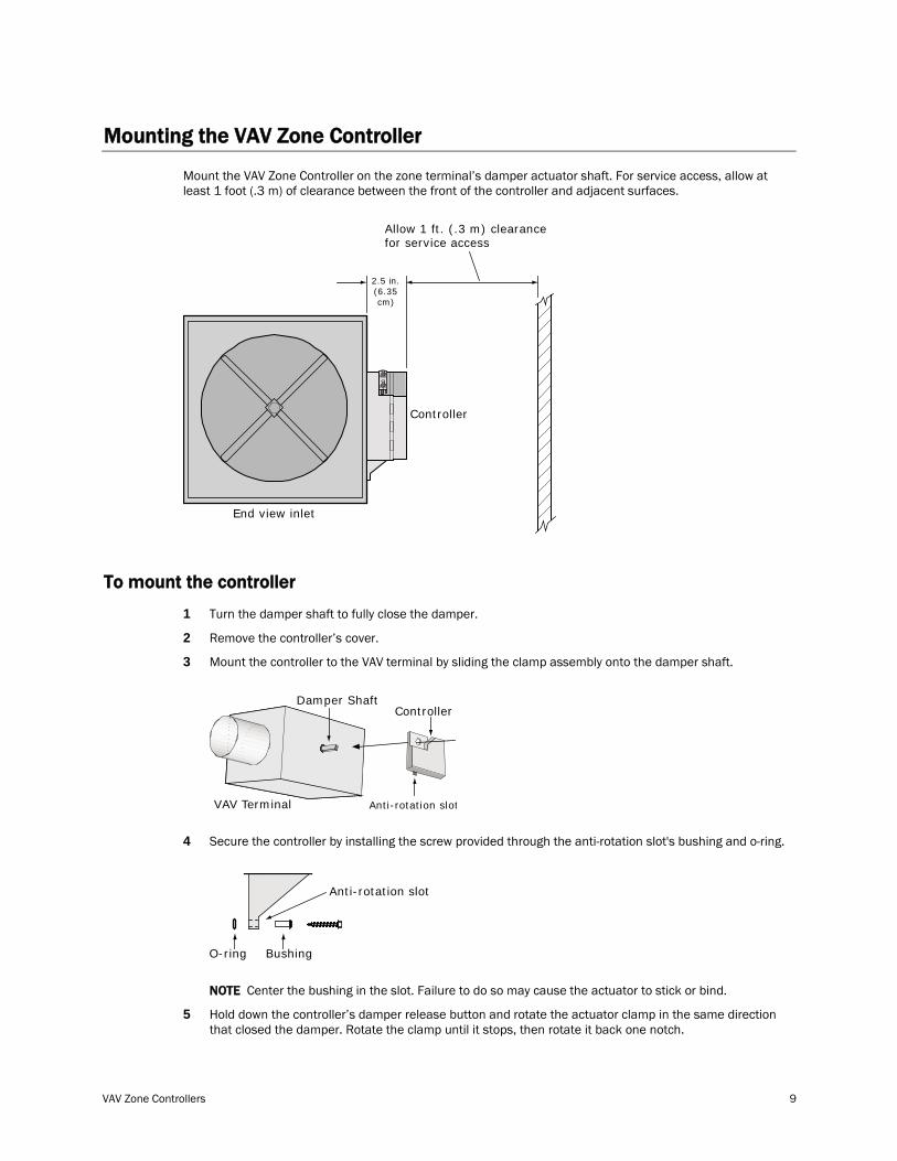
Mounting the VAV Zone Controller
Mount the VAV Zone Controller on the zone terminal’s damper actuator shaft. For service access, allow at least 1 foot (.3 m) of clearance between the front of the controller and adjacent surfaces.
End view inlet
Controller
Allow 1 ft. (.3 m) clearancefor service access
2.5 in.(6.35cm)
To mount the controller
1 Turn the damper shaft to fully close the damper.
2 Remove the controller’s cover.
3 Mount the controller to the VAV terminal by sliding the clamp assembly onto the damper shaft.
Damper Shaft
VAV Terminal
Controller
Anti-rotation slot
4 Secure the controller by installing the screw provided through the anti-rotation slot's bushing and o-ring.
O-ring Bushing
Anti-rotation slot
NOTE Center the bushing in the slot. Failure to do so may cause the actuator to stick or bind.
5 Hold down the controller’s damper release button and rotate the actuator clamp in the same direction that closed the damper. Rotate the clamp until it stops, then rotate it back one notch.
Installation
10 VAV Zone Controllers
Damperreleasebutton
5/8-in. nuts
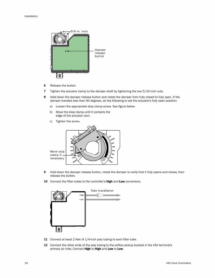
6 Release the button.
7 Tighten the actuator clamp to the damper shaft by tightening the two 5/16 inch nuts.
8 Hold down the damper release button and rotate the damper from fully closed to fully open. If the damper traveled less than 90 degrees, do the following to set the actuator's fully open position:
a) Loosen the appropriate stop clamp screw. See figure below.
b) Move the stop clamp until it contacts the edge of the actuator cam.
c) Tighten the screw.
Move stopclamp ifnecessary
9 Hold down the damper release button, rotate the damper to verify that it fully opens and closes, then release the button.
10 Connect the filter tubes to the controller's High and Low connectors.
High
Low
Tube installation
11 Connect at least 2 feet of 1/4-inch poly tubing to each filter tube.
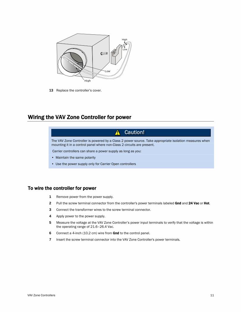
12 Connect the other ends of the poly tubing to the airflow pickup located in the VAV terminal's primary air inlet, Connect High to High and Low to Low.
VAV Zone Controllers 11
High
Low
Low
High
13 Replace the controller’s cover.
Wiring the VAV Zone Controller for power
The VAV Zone Controller is powered by a Class 2 power source. Take appropriate isolation measures when mounting it in a control panel where non-Class 2 circuits are present.
Carrier controllers can share a power supply as long as you:
• Maintain the same polarity
• Use the power supply only for Carrier Open controllers
To wire the controller for power
1 Remove power from the power supply.
2 Pull the screw terminal connector from the controller's power terminals labeled Gnd and 24 Vac or Hot.
3 Connect the transformer wires to the screw terminal connector.
4 Apply power to the power supply.
5 Measure the voltage at the VAV Zone Controller’s power input terminals to verify that the voltage is within the operating range of 21.6–26.4 Vac.
6 Connect a 4-inch (10.2 cm) wire from Gnd to the control panel.
7 Insert the screw terminal connector into the VAV Zone Controller's power terminals.
Installation
12 VAV Zone Controllers
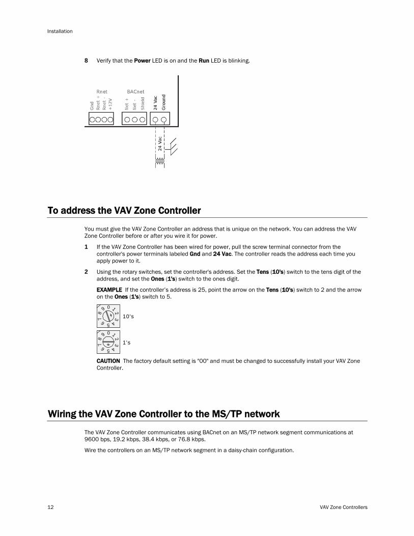
8 Verify that the Power LED is on and the Run LED is blinking.
To address the VAV Zone Controller
You must give the VAV Zone Controller an address that is unique on the network. You can address the VAV Zone Controller before or after you wire it for power.
1 If the VAV Zone Controller has been wired for power, pull the screw terminal connector from the controller's power terminals labeled Gnd and 24 Vac. The controller reads the address each time you apply power to it.
2 Using the rotary switches, set the controller's address. Set the Tens (10's) switch to the tens digit of the address, and set the Ones (1's) switch to the ones digit.
EXAMPLE If the controller’s address is 25, point the arrow on the Tens (10's) switch to 2 and the arrow on the Ones (1's) switch to 5.
10's
1's
1
3
45
2
78
9
6
0
1
3
45
2
78
9
6
0
CAUTION The factory default setting is "00" and must be changed to successfully install your VAV Zone Controller.
Wiring the VAV Zone Controller to the MS/TP network
The VAV Zone Controller communicates using BACnet on an MS/TP network segment communications at 9600 bps, 19.2 kbps, 38.4 kbps, or 76.8 kbps.
Wire the controllers on an MS/TP network segment in a daisy-chain configuration.
VAV Zone Controllers 13
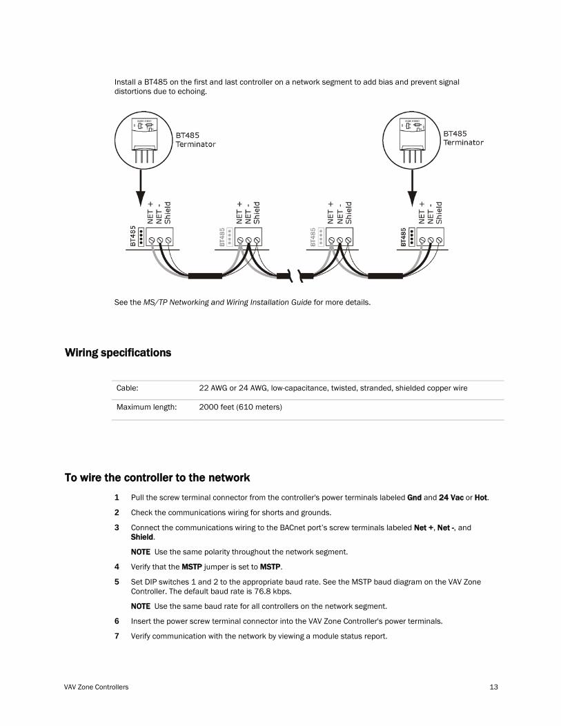
Install a BT485 on the first and last controller on a network segment to add bias and prevent signal distortions due to echoing.
See the MS/TP Networking and Wiring Installation Guide for more details.
Wiring specifications
Cable: 22 AWG or 24 AWG, low-capacitance, twisted, stranded, shielded copper wire
Maximum length: 2000 feet (610 meters)
To wire the controller to the network
1 Pull the screw terminal connector from the controller's power terminals labeled Gnd and 24 Vac or Hot.
2 Check the communications wiring for shorts and grounds.
3 Connect the communications wiring to the BACnet port’s screw terminals labeled Net +, Net -, and Shield.
NOTE Use the same polarity throughout the network segment.
4 Verify that the MSTP jumper is set to MSTP.
5 Set DIP switches 1 and 2 to the appropriate baud rate. See the MSTP baud diagram on the VAV Zone Controller. The default baud rate is 76.8 kbps.
NOTE Use the same baud rate for all controllers on the network segment.
6 Insert the power screw terminal connector into the VAV Zone Controller's power terminals.
7 Verify communication with the network by viewing a module status report.
Installation
14 VAV Zone Controllers
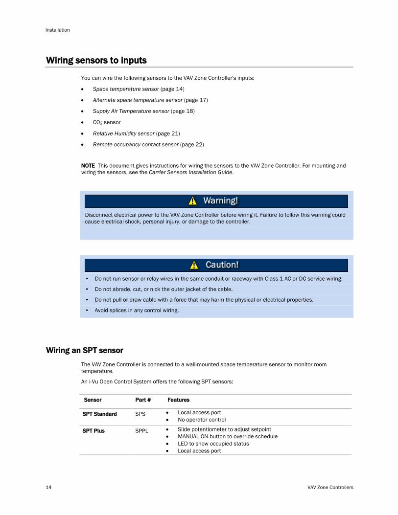
Wiring sensors to inputs
You can wire the following sensors to the VAV Zone Controller's inputs:
• Space temperature sensor (page 14)
• Alternate space temperature sensor (page 17)
• Supply Air Temperature sensor (page 18)
• CO2 sensor
• Relative Humidity sensor (page 21)
• Remote occupancy contact sensor (page 22)
NOTE This document gives instructions for wiring the sensors to the VAV Zone Controller. For mounting and wiring the sensors, see the Carrier Sensors Installation Guide.
Disconnect electrical power to the VAV Zone Controller before wiring it. Failure to follow this warning could cause electrical shock, personal injury, or damage to the controller.
• Do not run sensor or relay wires in the same conduit or raceway with Class 1 AC or DC service wiring.
• Do not abrade, cut, or nick the outer jacket of the cable.
• Do not pull or draw cable with a force that may harm the physical or electrical properties.
• Avoid splices in any control wiring.
Wiring an SPT sensor
The VAV Zone Controller is connected to a wall-mounted space temperature sensor to monitor room temperature.
An i-Vu Open Control System offers the following SPT sensors:
Sensor Part # Features
SPS SPT Standard • Local access port • No operator control
SPPL SPT Plus • Slide potentiometer to adjust setpoint • MANUAL ON button to override schedule • LED to show occupied status • Local access port
VAV Zone Controllers 15
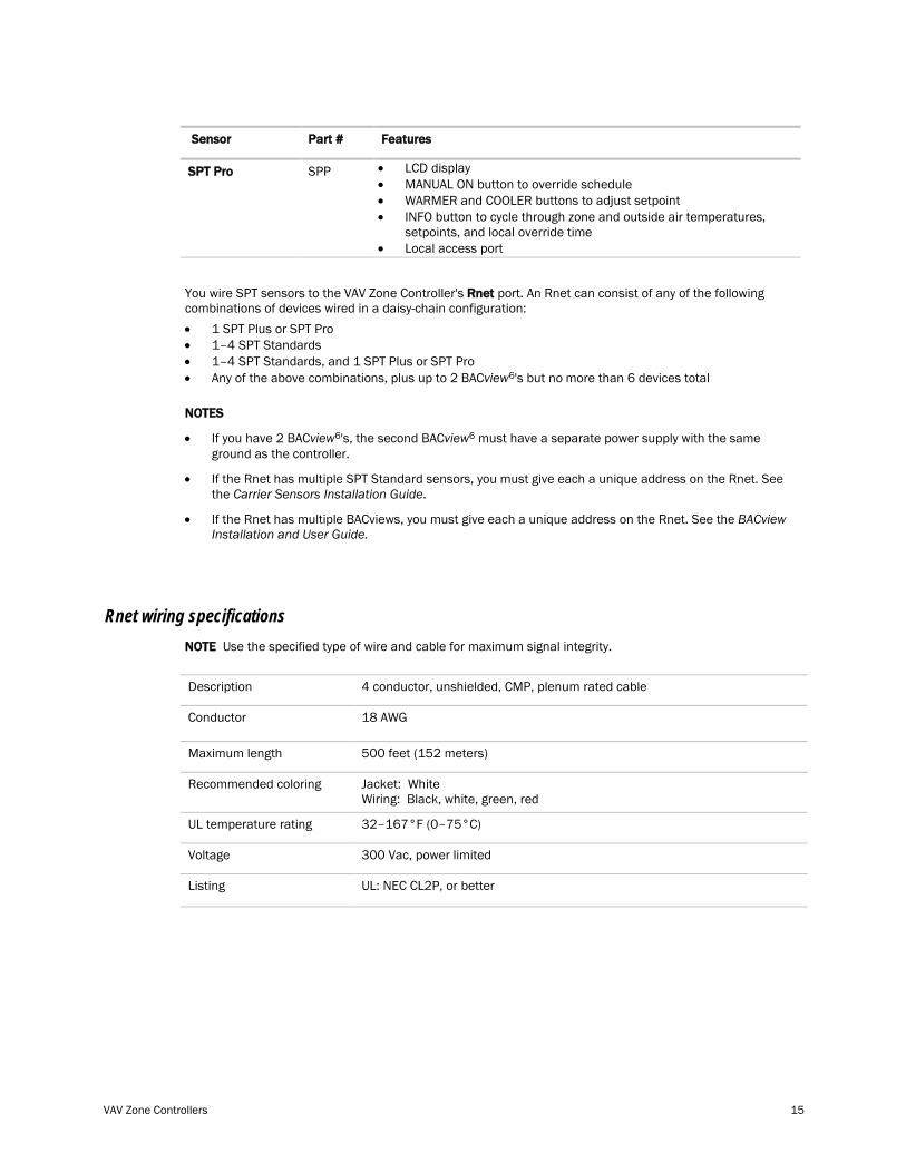
Sensor Part # Features
SPP SPT Pro • LCD display • MANUAL ON button to override schedule • WARMER and COOLER buttons to adjust setpoint • INFO button to cycle through zone and outside air temperatures,
setpoints, and local override time • Local access port
You wire SPT sensors to the VAV Zone Controller's Rnet port. An Rnet can consist of any of the following combinations of devices wired in a daisy-chain configuration: • 1 SPT Plus or SPT Pro • 1–4 SPT Standards • 1–4 SPT Standards, and 1 SPT Plus or SPT Pro • Any of the above combinations, plus up to 2 BACview6
NOTES
's but no more than 6 devices total
• If you have 2 BACview6's, the second BACview6 must have a separate power supply with the same ground as the controller.
• If the Rnet has multiple SPT Standard sensors, you must give each a unique address on the Rnet. See the Carrier Sensors Installation Guide.
• If the Rnet has multiple BACviews, you must give each a unique address on the Rnet. See the BACview Installation and User Guide.
Rnet wiring specifications NOTE Use the specified type of wire and cable for maximum signal integrity.
Description 4 conductor, unshielded, CMP, plenum rated cable
Conductor 18 AWG
Maximum length 500 feet (152 meters)
Recommended coloring Jacket: White Wiring: Black, white, green, red
UL temperature rating 32–167°F (0–75°C)
Voltage 300 Vac, power limited
Listing UL: NEC CL2P, or better
Installation
16 VAV Zone Controllers
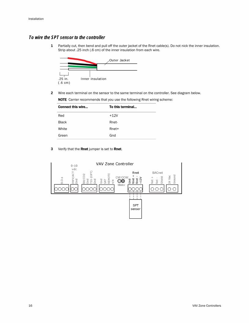
To wire the SPT sensor to the controller 1 Partially cut, then bend and pull off the outer jacket of the Rnet cable(s). Do not nick the inner insulation.
Strip about .25 inch (.6 cm) of the inner insulation from each wire.
Outer Jacket
Inner insulation.25 in.(.6 cm)
2 Wire each terminal on the sensor to the same terminal on the controller. See diagram below.
NOTE Carrier recommends that you use the following Rnet wiring scheme:
Connect this wire...
Red
To this terminal...
Black
White
Green
+12V
Rnet-
Rnet+
Gnd
3 Verify that the Rnet jumper is set to Rnet.
VAV Zone Controllers 17
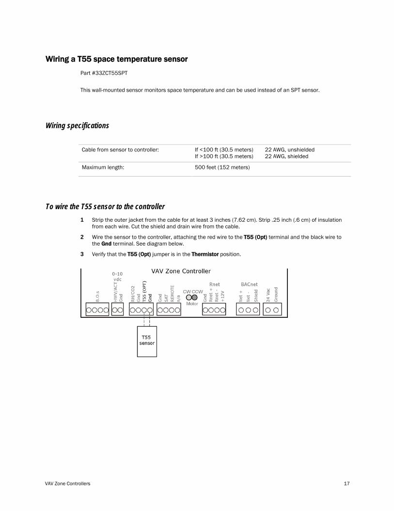
Wiring a T55 space temperature sensor
Part #33ZCT55SPT
This wall-mounted sensor monitors space temperature and can be used instead of an SPT sensor.
Wiring specifications
Cable from sensor to controller: If <100 ft (30.5 meters) 22 AWG, unshielded If >100 ft (30.5 meters) 22 AWG, shielded
Maximum length: 500 feet (152 meters)
To wire the T55 sensor to the controller 1 Strip the outer jacket from the cable for at least 3 inches (7.62 cm). Strip .25 inch (.6 cm) of insulation
from each wire. Cut the shield and drain wire from the cable.
2 Wire the sensor to the controller, attaching the red wire to the T55 (Opt) terminal and the black wire to the Gnd terminal. See diagram below.
3 Verify that the T55 (Opt) jumper is in the Thermistor position.
Installation
18 VAV Zone Controllers
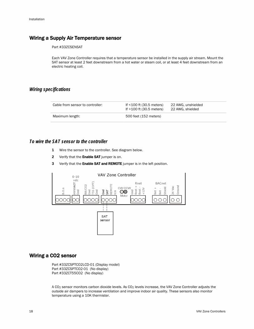
Wiring a Supply Air Temperature sensor
Part #33ZCSENSAT
Each VAV Zone Controller requires that a temperature sensor be installed in the supply air stream. Mount the SAT sensor at least 2 feet downstream from a hot water or steam coil, or at least 4 feet downstream from an electric heating coil.
Wiring specifications
Cable from sensor to controller: If <100 ft (30.5 meters) 22 AWG, unshielded If >100 ft (30.5 meters) 22 AWG, shielded
Maximum length: 500 feet (152 meters)
To wire the SAT sensor to the controller 1 Wire the sensor to the controller. See diagram below.
2 Verify that the Enable SAT jumper is on.
3 Verify that the Enable SAT and REMOTE jumper is in the left position.
Wiring a CO2 sensor
Part #33ZCSPTCO2LCD-01 (Display model) Part #33ZCSPTCO2-01 (No display) Part #33ZCT55CO2 (No display)
A CO2 sensor monitors carbon dioxide levels. As CO2 levels increase, the VAV Zone Controller adjusts the outside air dampers to increase ventilation and improve indoor air quality. These sensors also monitor temperature using a 10K thermister.
VAV Zone Controllers 19
A CO2 sensor can be wall-mounted or mounted in a return air duct. (Duct installation requires an Aspirator Box Accessory - Part #33ZCASPCO2.)
The sensor has a range of 0–2000 ppm and a linear 4-20 mA output. This is converted to 1-5 Vdc by a 250 Ohm, 1/4 watt, 2% tolerance resistor connected across the zone controller's CO2 input terminals.
NOTE Do not use a relative humidity sensor and CO2 sensor on the same zone controller.
Wiring specifications
Cable from sensor to controller: If <100 ft (30.5 meters) 22 AWG, unshielded If >100 ft (30.5 meters) 22 AWG, shielded
Maximum length: 500 feet (152 meters)
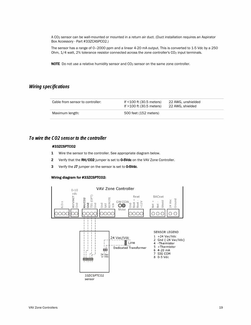
To wire the CO2 sensor to the controller #33ZCSPTCO2
1 Wire the sensor to the controller. See appropriate diagram below.
2 Verify that the RH/CO2 jumper is set to 0-5Vdc on the VAV Zone Controller.
3 Verify the J7 jumper on the sensor is set to 0-5Vdc.
Wiring diagram for #33ZCSPTCO2:
Installation
20 VAV Zone Controllers
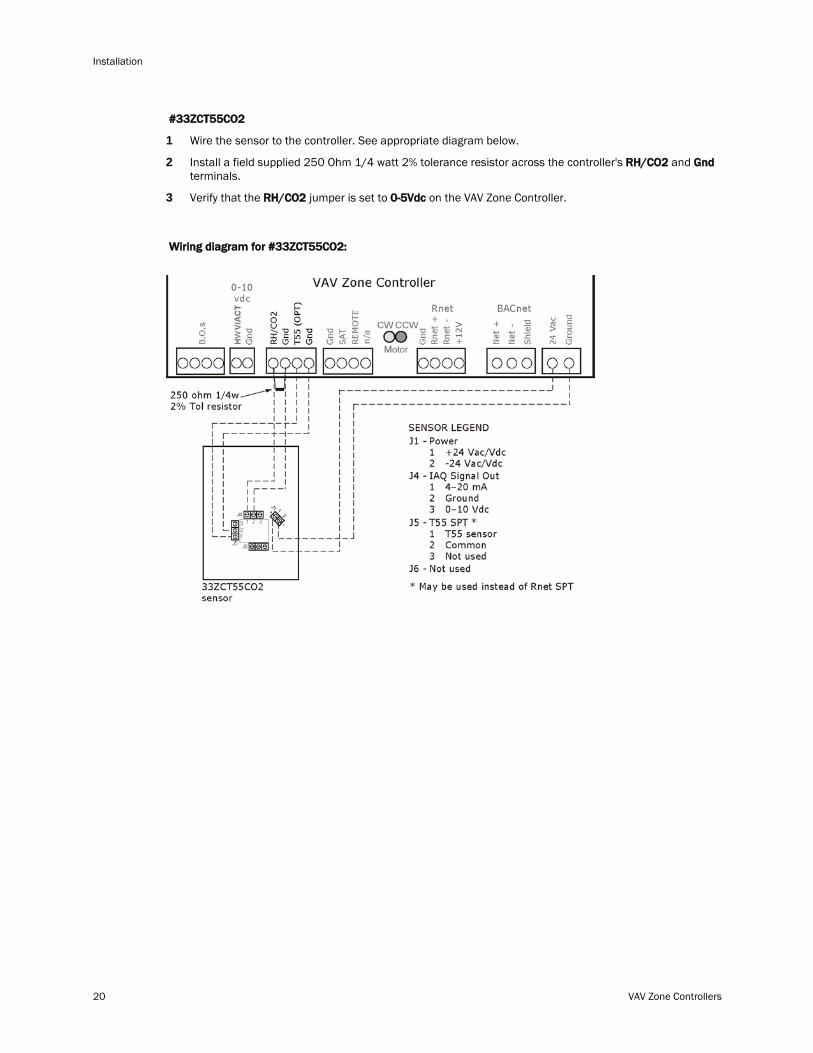
#33ZCT55CO2
1 Wire the sensor to the controller. See appropriate diagram below.
2 Install a field supplied 250 Ohm 1/4 watt 2% tolerance resistor across the controller's RH/CO2 and Gnd terminals.
3 Verify that the RH/CO2 jumper is set to 0-5Vdc on the VAV Zone Controller.
Wiring diagram for #33ZCT55CO2:
VAV Zone Controllers 21
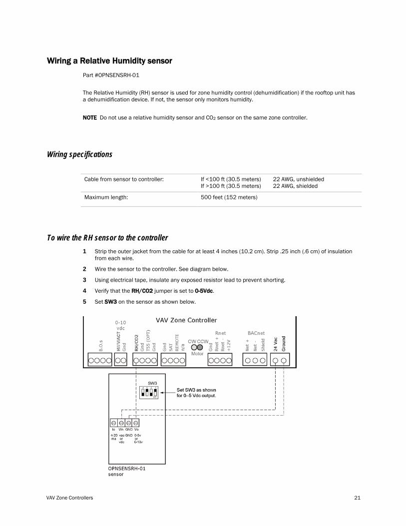
Wiring a Relative Humidity sensor
Part #OPNSENSRH-01
The Relative Humidity (RH) sensor is used for zone humidity control (dehumidification) if the rooftop unit has a dehumidification device. If not, the sensor only monitors humidity.
NOTE Do not use a relative humidity sensor and CO2 sensor on the same zone controller.
Wiring specifications
Cable from sensor to controller: If <100 ft (30.5 meters) 22 AWG, unshielded If >100 ft (30.5 meters) 22 AWG, shielded
Maximum length: 500 feet (152 meters)
To wire the RH sensor to the controller 1 Strip the outer jacket from the cable for at least 4 inches (10.2 cm). Strip .25 inch (.6 cm) of insulation
from each wire.
2 Wire the sensor to the controller. See diagram below.
3 Using electrical tape, insulate any exposed resistor lead to prevent shorting.
4 Verify that the RH/CO2 jumper is set to 0-5Vdc.
5 Set SW3 on the sensor as shown below.
Installation
22 VAV Zone Controllers
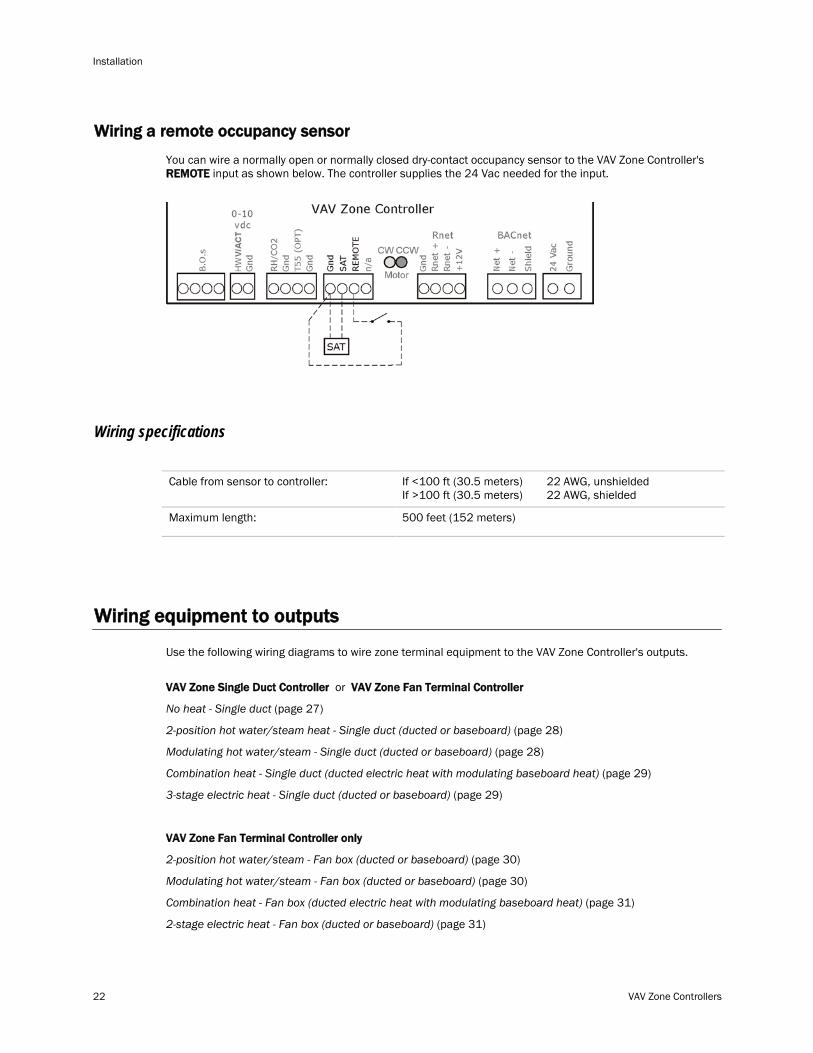
Wiring a remote occupancy sensor
You can wire a normally open or normally closed dry-contact occupancy sensor to the VAV Zone Controller's REMOTE input as shown below. The controller supplies the 24 Vac needed for the input.
Wiring specifications
Cable from sensor to controller: If <100 ft (30.5 meters) 22 AWG, unshielded If >100 ft (30.5 meters) 22 AWG, shielded
Maximum length: 500 feet (152 meters)
Wiring equipment to outputs
Use the following wiring diagrams to wire zone terminal equipment to the VAV Zone Controller's outputs.
VAV Zone Single Duct Controller or VAV Zone Fan Terminal Controller
No heat - Single duct (page 27)
2-position hot water/steam heat - Single duct (ducted or baseboard) (page 28)
Modulating hot water/steam - Single duct (ducted or baseboard) (page 28)
Combination heat - Single duct (ducted electric heat with modulating baseboard heat) (page 29)
3-stage electric heat - Single duct (ducted or baseboard) (page 29)
VAV Zone Fan Terminal Controller only
2-position hot water/steam - Fan box (ducted or baseboard) (page 30)
Modulating hot water/steam - Fan box (ducted or baseboard) (page 30)
Combination heat - Fan box (ducted electric heat with modulating baseboard heat) (page 31)
2-stage electric heat - Fan box (ducted or baseboard) (page 31)
VAV Zone Controllers 23
Disconnect electrical power to the VAV Zone Controller before wiring it. Failure to follow this warning could cause electrical shock, personal injury, or damage to the controller.
Wiring specifications
To size output wiring, consider the following:
• Total loop distance from the power supply to the controller, and then to the controlled device
NOTE Include the total distance of actual wire. For 2-conductor wires, this is twice the cable length.
• Acceptable voltage drop in the wire from the controller to the controlled device
• Resistance (Ohms) of the chosen wire gauge
• Maximum current (Amps) the controlled device requires to operate
Balancing the system using i-Vu/Field Assistant
Most VAV system airflow designs are based on cooling requirements which require a greater cfm flow than heating requirements. Using this balancing procedure, you will adjust the cooling airflow first. If the heating and cooling maximum airflow requirements are the same, you will not need to balance the heating airflow.
NOTE We recommend that the total heating minimum airflow settings for all the zones in the system be set to maintain the air source’s design minimum heat cfm airflow across its heat exchanger to prevent damage to the equipment.
The following procedures instruct you to use i-Vu or Field Assistant to balance the system. However, you can also use the Test & Balance tool that includes global commands to assist you in balancing the system.
Step 1: Prepare for balancing 1 Log in to i-Vu with an Administrator or Installer security level, or use Field Assistant.
2 Make sure the air source and its controller have been properly started and can run as a stand-alone unit.
3 Make sure all zone controllers have been addressed, commissioned, and started.
4 If a manual damper is installed upstream of the zone damper, verify that it is fully open before any balancing occurs.
5 Verify that any zone controller supplying multiple diffusers has a manual balancing damper installed on each duct for balancing the design airflow through each diffuser.
6 Disable the air source heating and cooling outputs using one of the following methods:
○ Physically disconnect the air source controller’s output wiring to the unit, then enable the fan.
○ In the i-Vu or Field Assistant tree, select the AHU controller. Go to Properties > Configuration > Equipment Enable/Disable > Service Test and enable Test and Balance Command.
7 Verify that the air source's supply static pressure setpoint is set to the system's design specification and that it does maintain the setpoint.
Installation
24 VAV Zone Controllers
Step 2: Balance each zone 1 In the i-Vu or Field Assistant tree, select the zone controller that is physically closest to the air source. Go
to Properties > Equipment > Configuration > Service Configuration > Flow Control > Details tab.
2 Do one of the following:
○ Single Duct or Parallel Fan zone terminals – Click Cool Max Airflow to override the zone control and increase the airflow to the cooling maximum cfm. Check the zone for design cooling maximum airflow using certified measuring devices. Enter the measured cfm and click the arrow to enter the current sensor reading value.
○ Series Fan zone terminals – Click Damper Full Close to override the zone damper to its fully closed position. Wait 30 seconds after the damper is closed, select the Fan's Lock value to checkbox, then select On in the droplist. Click Apply. You must follow this procedure to prevent the fan from turning backwards. Check the zone for design cooling maximum airflow using certified measuring devices. See the zone terminal manufacturer's instructions to adjust the fan speed to meet design airflow requirements. After you set the fan speed to deliver the Cool Max Airflow, click the Cool Max Airflow. Verify the airflow using a certified measuring device. Enter the measured cfm and press the arrow to enter the current sensor reading value. Verify that the zone terminal plenum air intakes do not have a positive airflow.
3 Check all branch duct terminal registers for design flow. If necessary, adjust the manual volume dampers in the branch ducts.
4 Single Duct or Parallel Fan zone terminals - Click Occupied Min Airflow to set the zone damper to its minimum airflow position. Verify the airflow using a certified measuring device. Enter the measured cfm and click the arrow to enter the current sensor reading value.
5 Parallel Fan Zone Terminals only - To adjust Parallel Fan airflow, make sure Occupied Min Airflow is selected, select the Fan's Lock value to checkbox, then select On in the droplist. Click Apply. See the zone terminal manufacturer's instructions on adjusting the fan speed to meet design airflow requirements. When finished, clear the Fan's Lock value to checkbox.
6 If the terminal has ducted reheat, select the Flow Setpoint in the Locks section and enter Auxiliary Heat Min Airflow if it is greater than the Occupied Min Airflow. Select Auxheat and enter 100%. Click Apply. Verify the supply air temperature rises for ducted heat. For non-ducted heat, physically verify that the heat is energized. Deselect a Flow Setpoint and Auxheat and click Apply when finished.
7 Repeat steps 1 through 6 for each zone until all zones have been balanced. Make sure that you select Automatic Control before moving on to the next zone.
Balancing the system using Test & Balance tool
Use the Test & Balance tool to manipulate the controllers associated with an air source, but not the air source itself or heating and cooling equipment such as chillers and boilers. See the Test & Balance Help files for more information on using the tool.
Most VAV system airflow designs are based on cooling requirements which require a greater cfm flow than heating requirements. Using this balancing procedure, you adjust the cooling airflow first. If the heating and cooling maximum airflow requirements are the same, you will not need to balance the heating airflow.
NOTE We recommend that the total heating minimum airflow settings for all the zones in the system be set to maintain the air source’s design minimum heat cfm airflow across its heat exchanger to prevent damage to the equipment.
VAV Zone Controllers 25
To calibrate VAV Zone airflow 1 Select the VAV Zone air terminal in the tree.
NOTE You can select View > Device ID or View > Primary Use to show this information next to each item in the tree.
2 Select the Test and Balance tab.
NOTE If or appear on the status bar, see Air terminal calibration status to determine what you must do before calibration can occur.
3 Verify that the air source is off and that airflow has stopped.
4 Click Zero Calibrate.
NOTE The table below describes each damper command. Commands with a are required. Optional commands improve system accuracy. Do these in order from top to bottom for best results.
5 The status bar shows Damper Moving. Wait until it shows Damper Ready.
6 If the controller has an external actuator, do the following:
a) Type the Measured Flow in the fields beside Zero Calibrate
b) Click the
.
Current Sensor Reading button to copy the value to the Sensor Reading
7 Turn on the air source.
field, or type an adjusted value in the field.
8 For each additional calibration step that you want to perform, do the following:
a) Click its Damper Command button.
b) Wait for Damper Ready
c) Enter the
.
Measured Flow and Sensor Reading
9 Click Apply to send your changes to the controller and update the Last Calibration Date on the air source's page.
as described in step 6.
NOTE If desired, you can click Apply after each calibration step.
10 Remove any locks you have applied. See To view, lock, or unlock an air terminal function.
11 Click Automatic to return the controller to normal operation.
NOTES
• For Cool Max, Heat Max, and Occupied Min – When the setpoint is reached and stable, you can select Lock damper at current open position on the Locks tab to prevent damper movement while you take flow readings.
• You can repeat a calibration step to further calibrate the airflow sensor.
• An airflow sensor only reports air delivered from the air source. To adjust the CFM of variable speed fans in parallel VAV reheat, close the primary air damper.
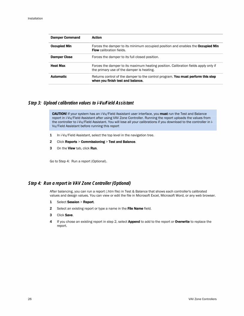
Damper Command Action
Zero Calibrate Closes the damper, takes a number of flow samples, then sets the zero calibration.
Damper Open Opens damper fully and enables the Damper Open calibration fields.
Forces the damper to its maximum cooling position. Calibration fields apply only if the primary use of this damper is cooling.
Cool Max
Installation
26 VAV Zone Controllers
Damper Command Action
Forces the damper to its minimum occupied position and enables the Occupied Min Occupied Min Flow calibration fields.
Forces the damper to its full closed position. Damper Close
Forces the damper to its maximum heating position. Calibration fields apply only if the primary use of the damper is heating.
Heat Max
Returns control of the damper to the control program. Automatic
You must perform this step when you finish test and balance.
Step 3: Upload calibration values to i-Vu/Field Assistant
CAUTION! If your system has an i-Vu/Field Assistant user interface, you must
1 In i-Vu/Field Assistant, select the top level in the navigation tree.
run the Test and Balance report in i-Vu/Field Assistant after using VAV Zone Controller. Running the report uploads the values from the controller to i-Vu/Field Assistant. You will lose all your calibrations if you download to the controller in i-Vu/Field Assistant before running this report
2 Click Reports > Commissioning > Test and Balance.
3 On the View tab, click Run.
Go to Step 4: Run a report (Optional).
Step 4: Run a report in VAV Zone Controller (Optional) After balancing, you can run a report (.htm file) in Test & Balance that shows each controller's calibrated values and design values. You can view or edit the file in Microsoft Excel, Microsoft Word, or any web browser.
1 Select Session > Report.
2 Select an existing report or type a name in the File Name field.
3 Click Save.
4 If you chose an existing report in step 2, select Append to add to the report or Overwrite to replace the report.
VAV Zone Controllers 27
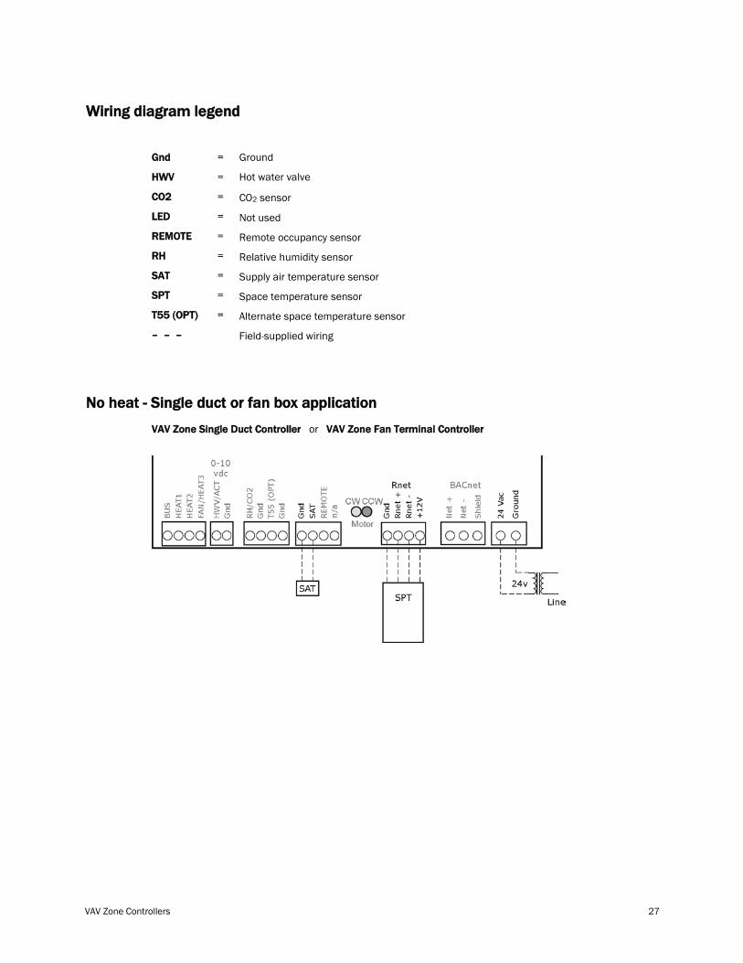
Wiring diagram legend
Gnd
HWV
CO2
LED
REMOTE
RH
SAT
SPT
T55 (OPT)
– – –
=
=
=
=
=
=
=
=
=
Ground
Hot water valve
CO2 sensor
Not used
Remote occupancy sensor
Relative humidity sensor
Supply air temperature sensor
Space temperature sensor
Alternate space temperature sensor
Field-supplied wiring
No heat - Single duct or fan box application
VAV Zone Single Duct Controller or VAV Zone Fan Terminal Controller
Installation
28 VAV Zone Controllers
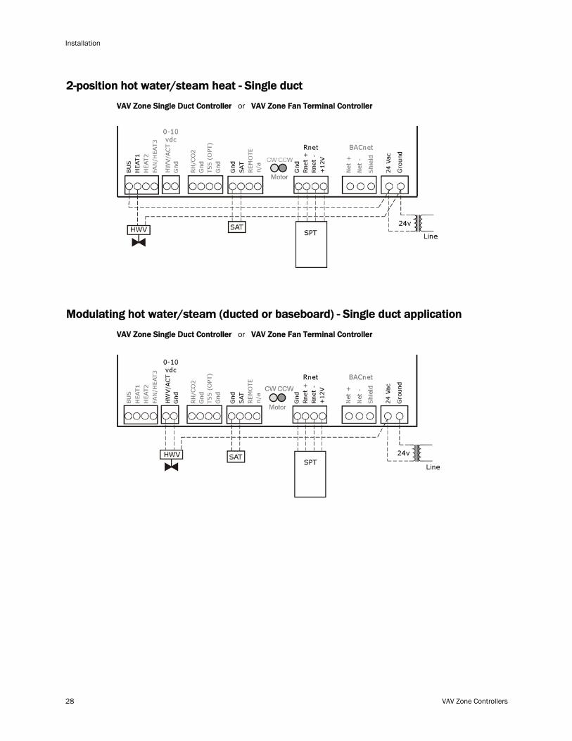
2-position hot water/steam heat - Single duct
VAV Zone Single Duct Controller or VAV Zone Fan Terminal Controller
Modulating hot water/steam (ducted or baseboard) - Single duct application
VAV Zone Single Duct Controller or VAV Zone Fan Terminal Controller
VAV Zone Controllers 29
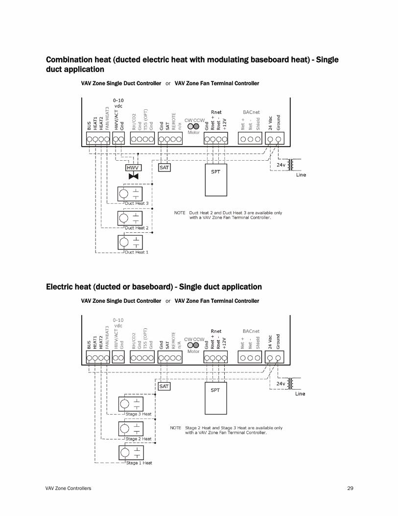
Combination heat (ducted electric heat with modulating baseboard heat) - Single duct application
VAV Zone Single Duct Controller or VAV Zone Fan Terminal Controller
Electric heat (ducted or baseboard) - Single duct application
VAV Zone Single Duct Controller or VAV Zone Fan Terminal Controller
Installation
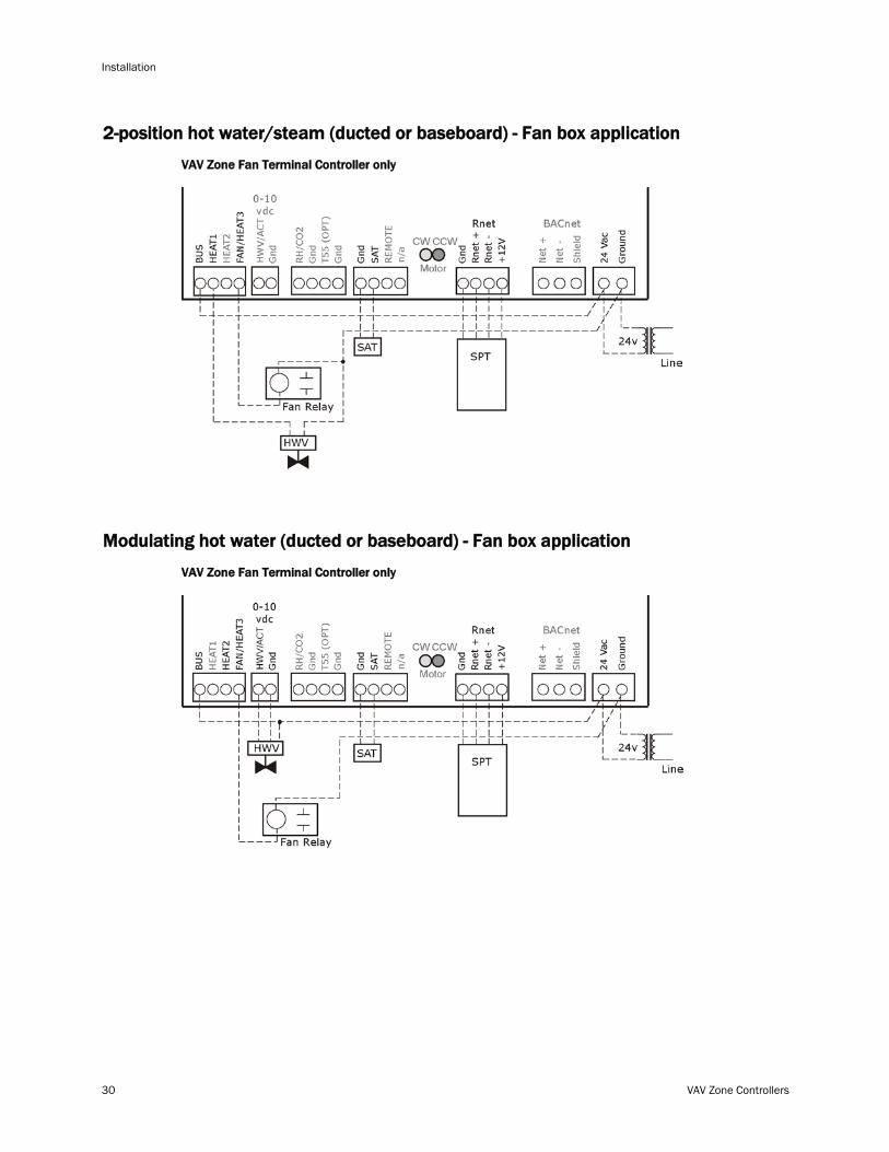
30 VAV Zone Controllers
2-position hot water/steam (ducted or baseboard) - Fan box application
VAV Zone Fan Terminal Controller only
Modulating hot water (ducted or baseboard) - Fan box application
VAV Zone Fan Terminal Controller only
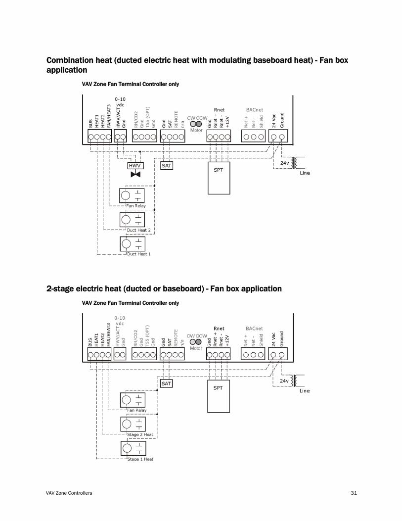
VAV Zone Controllers 31
Combination heat (ducted electric heat with modulating baseboard heat) - Fan box application
VAV Zone Fan Terminal Controller only
2-stage electric heat (ducted or baseboard) - Fan box application
VAV Zone Fan Terminal Controller only
Installation
32 VAV Zone Controllers
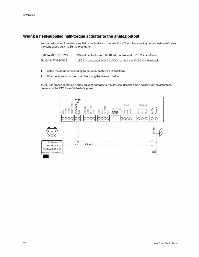
Wiring a field-supplied high-torque actuator to the analog output
You can wire one of the following Belimo actuators to the VAV Zone Controller's analog output instead of using the controller's built-in, 35 in.-lb actuator.
NMX24-MFT P-10028 90 in.-lb actuator with 0–10 Vdc control and 0–10 Vdc feedback
AMX24-MFT P-10028 180 in.-lb actuator with 0–10 Vdc control and 0–10 Vdc feedback
1 Install the actuator according to the manufacturer's instructions.
2 Wire the actuator to the controller using the diagram below.
NOTE For proper operation and to prevent damage to the devices, use the same polarity for the actuator's power and the VAV Zone Controller's power.
VAV Zone Controllers 33
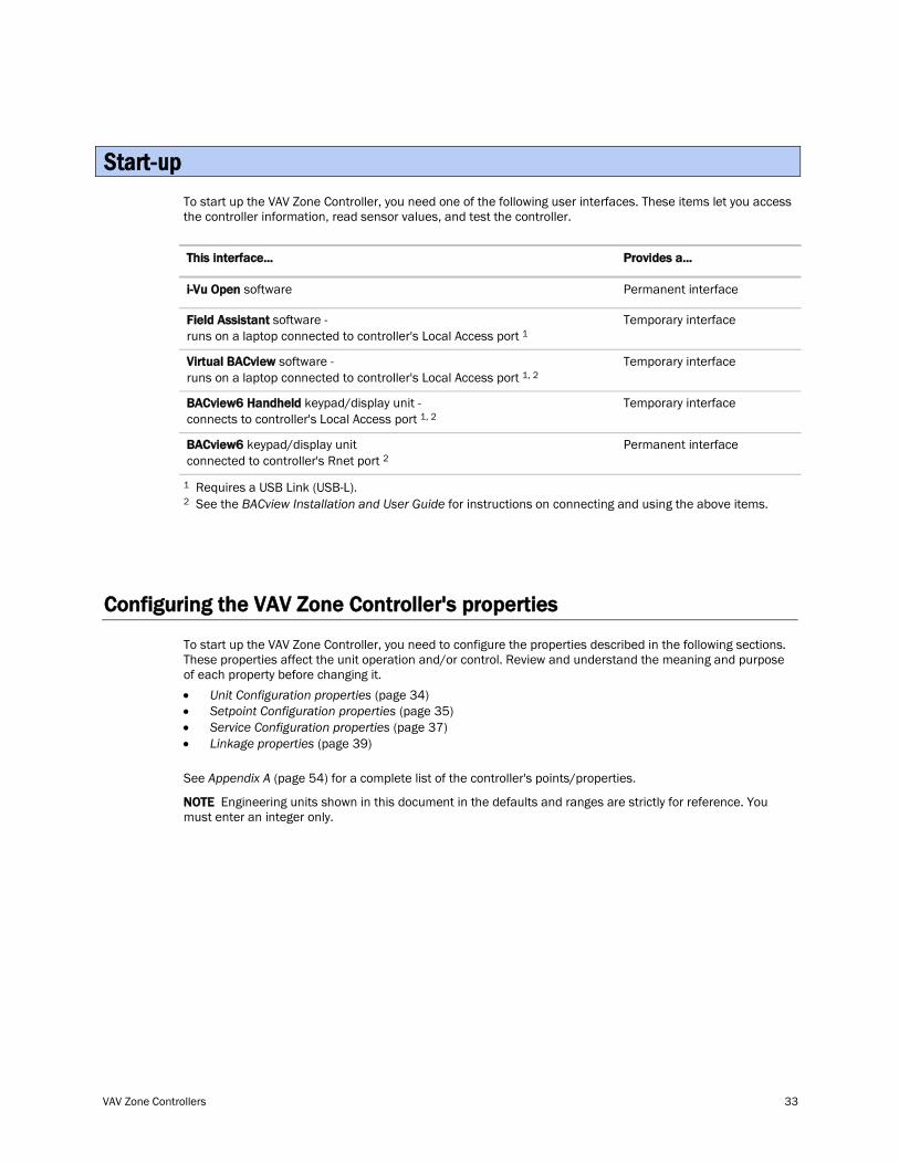
To start up the VAV Zone Controller, you need one of the following user interfaces. These items let you access the controller information, read sensor values, and test the controller.
This interface... Provides a...
i-Vu Open Permanent interface software
Field Assistant software - runs on a laptop connected to controller's Local Access port
Temporary interface 1
Virtual BACview software - runs on a laptop connected to controller's Local Access port
Temporary interface 1, 2
BACview6 Handheld keypad/display unit - connects to controller's Local Access port
Temporary interface 1, 2
BACview6 keypad/display unit connected to controller's Rnet port
Permanent interface 2
1 Requires a USB Link (USB-L). 2 See the BACview Installation and User Guide for instructions on connecting and using the above items.
Configuring the VAV Zone Controller's properties
To start up the VAV Zone Controller, you need to configure the properties described in the following sections. These properties affect the unit operation and/or control. Review and understand the meaning and purpose of each property before changing it. • Unit Configuration properties 34 (page ) • Setpoint Configuration properties 35 (page ) • Service Configuration properties 37 (page ) • Linkage properties 39 (page ) See Appendix A (page 54) for a complete list of the controller's points/properties.
NOTE Engineering units shown in this document in the defaults and ranges are strictly for reference. You must enter an integer only.
Start-up
Start-up
34 VAV Zone Controllers
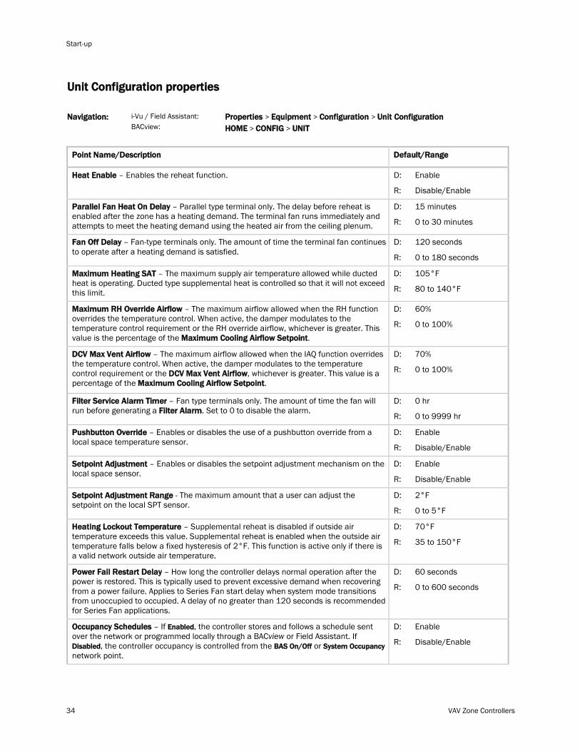
Unit Configuration properties
i-Vu / Field Assistant: Navigation: BACview:
Properties > Equipment > Configuration > Unit Configuration HOME > CONFIG >
UNIT
Point Name/Description Default/Range
Heat Enable D: – Enables the reheat function.
R:
Enable
Disable/Enable
Parallel Fan Heat On Delay D: – Parallel type terminal only. The delay before reheat is enabled after the zone has a heating demand. The terminal fan runs immediately and attempts to meet the heating demand using the heated air from the ceiling plenum. R:
15 minutes
0 to 30 minutes
Fan Off Delay D: – Fan-type terminals only. The amount of time the terminal fan continues to operate after a heating demand is satisfied.
R:
120 seconds
0 to 180 seconds
Maximum Heating SAT D: – The maximum supply air temperature allowed while ducted heat is operating. Ducted type supplemental heat is controlled so that it will not exceed this limit. R:
105°F
80 to 140°F
Maximum RH Override Airflow – The maximum airflow allowed when the RH function overrides the temperature control. When active, the damper modulates to the temperature control requirement or the RH override airflow, whichever is greater. This value is the percentage of the Maximum Cooling Airflow Setpoint
D:
. R:
60%
0 to 100%
DCV Max Vent Airflow – The maximum airflow allowed when the IAQ function overrides the temperature control. When active, the damper modulates to the temperature control requirement or the DCV Max Vent Airflow, whichever is greater. This value is a percentage of the Maximum Cooling Airflow Setpoint
D:
. R:
70%
0 to 100%
Filter Service Alarm Timer – Fan type terminals only. The amount of time the fan will run before generating a Filter Alarm
D: . Set to 0 to disable the alarm.
R:
0 hr
0 to 9999 hr
Pushbutton Override D: – Enables or disables the use of a pushbutton override from a local space temperature sensor.
R:
Enable
Disable/Enable
Setpoint Adjustment D: – Enables or disables the setpoint adjustment mechanism on the local space sensor.
R:
Enable
Disable/Enable
Setpoint Adjustment Range D: - The maximum amount that a user can adjust the setpoint on the local SPT sensor.
R:
2°F
0 to 5°F
Heating Lockout Temperature D: – Supplemental reheat is disabled if outside air temperature exceeds this value. Supplemental reheat is enabled when the outside air temperature falls below a fixed hysteresis of 2°F. This function is active only if there is a valid network outside air temperature.
R:
70°F
35 to 150°F
Power Fail Restart Delay D: – How long the controller delays normal operation after the power is restored. This is typically used to prevent excessive demand when recovering from a power failure. Applies to Series Fan start delay when system mode transitions from unoccupied to occupied. A delay of no greater than 120 seconds is recommended for Series Fan applications.
R:
60 seconds
0 to 600 seconds
Occupancy Schedules – If Enabled, the controller stores and follows a schedule sent over the network or programmed locally through a BACview or Field Assistant. If Disabled, the controller occupancy is controlled from the BAS On/Off or System Occupancy
D:
network point. R:
Enable
Disable/Enable
VAV Zone Controllers 35
Point Name/Description Default/Range
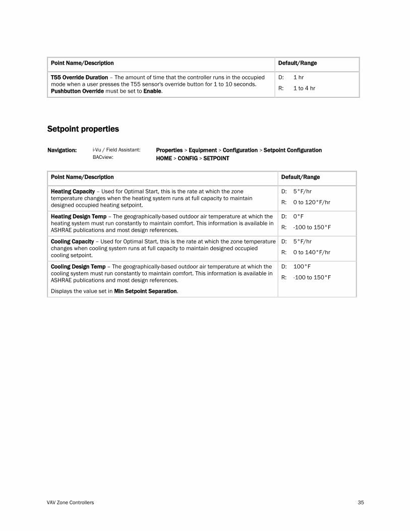
T55 Override Duration – The amount of time that the controller runs in the occupied mode when a user presses the T55 sensor's override button for 1 to 10 seconds. Pushbutton Override must be set to Enable
D:
. R:
1 hr
1 to 4 hr
Setpoint properties
i-Vu / Field Assistant: Navigation: BACview:
Properties > Equipment > Configuration > Setpoint Configuration HOME > CONFIG >
SETPOINT
Point Name/Description Default/Range
Heating Capacity D: – Used for Optimal Start, this is the rate at which the zone temperature changes when the heating system runs at full capacity to maintain designed occupied heating setpoint. R:
5°F/hr
0 to 120°F/hr
Heating Design Temp D: – The geographically-based outdoor air temperature at which the heating system must run constantly to maintain comfort. This information is available in ASHRAE publications and most design references. R:
0°F
-100 to 150°F
Cooling Capacity D: – Used for Optimal Start, this is the rate at which the zone temperature changes when cooling system runs at full capacity to maintain designed occupied cooling setpoint. R:
5°F/hr
0 to 140°F/hr
Cooling Design Temp
Displays the value set in
– The geographically-based outdoor air temperature at which the cooling system must run constantly to maintain comfort. This information is available in ASHRAE publications and most design references.
Min Setpoint Separation
D:
.
R:
100°F
-100 to 150°F
Start-up
36 VAV Zone Controllers
Point Name/Description Default/Range
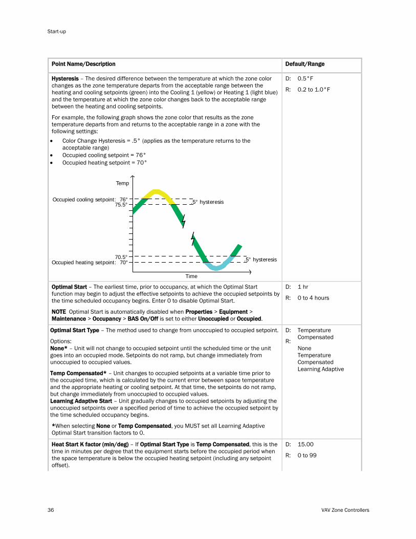
Hysteresis
For example, the following graph shows the zone color that results as the zone temperature departs from and returns to the acceptable range in a zone with the following settings:
– The desired difference between the temperature at which the zone color changes as the zone temperature departs from the acceptable range between the heating and cooling setpoints (green) into the Cooling 1 (yellow) or Heating 1 (light blue) and the temperature at which the zone color changes back to the acceptable range between the heating and cooling setpoints.
• Color Change Hysteresis = .5° (applies as the temperature returns to the acceptable range)
• Occupied cooling setpoint = 76° • Occupied heating setpoint = 70°
Time
Temp
Occupied heating setpoint: 70°
75.5°
70.5°
Occupied cooling setpoint: 76° .5° hysteresis
.5° hysteresis
D:
R:
0.5°F
0.2 to 1.0°F
Optimal Start – The earliest time, prior to occupancy, at which the Optimal Start function may begin to adjust the effective setpoints to achieve the occupied setpoints by the time scheduled occupancy begins. Enter 0 to disable Optimal Start.
NOTE Optimal Start is automatically disabled when Properties > Equipment > Maintenance > Occupancy > BAS On/Off is set to either Unoccupied or Occupied
D:
.
R:
1 hr
0 to 4 hours
Optimal Start Type – The method used to change from unoccupied to occupied setpoint.
Options: None* – Unit will not change to occupied setpoint until the scheduled time or the unit goes into an occupied mode. Setpoints do not ramp, but change immediately from unoccupied to occupied values.
Temp Compensated* – Unit changes to occupied setpoints at a variable time prior to the occupied time, which is calculated by the current error between space temperature and the appropriate heating or cooling setpoint. At that time, the setpoints do not ramp, but change immediately from unoccupied to occupied values. Learning Adaptive Start – Unit gradually changes to occupied setpoints by adjusting the unoccupied setpoints over a specified period of time to achieve the occupied setpoint by the time scheduled occupancy begins.
*When selecting None or Temp Compensated
D:
, you MUST set all Learning Adaptive Optimal Start transition factors to 0.
R:
Temperature Compensated
None Temperature Compensated Learning Adaptive
Heat Start K factor (min/deg) – If Optimal Start Type is Temp Compensated D: , this is the time in minutes per degree that the equipment starts before the occupied period when the space temperature is below the occupied heating setpoint (including any setpoint offset).
R:
15.00
0 to 99
VAV Zone Controllers 37
Point Name/Description Default/Range
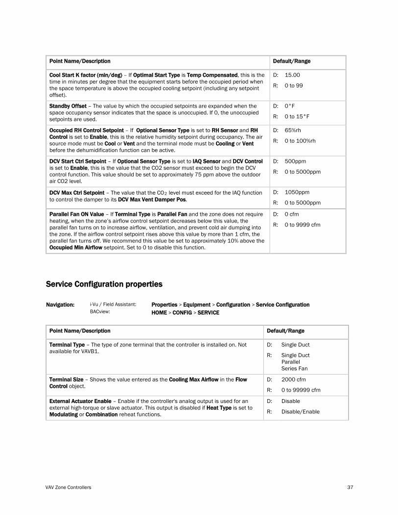
Cool Start K factor (min/deg) – If Optimal Start Type is Temp Compensated D: , this is the time in minutes per degree that the equipment starts before the occupied period when the space temperature is above the occupied cooling setpoint (including any setpoint offset).
R:
15.00
0 to 99
Standby Offset D: – The value by which the occupied setpoints are expanded when the space occupancy sensor indicates that the space is unoccupied. If 0, the unoccupied setpoints are used. R:
0°F
0 to 15°F
Occupied RH Control Setpoint – If Optional Sensor Type is set to RH Sensor and RH Control is set to Enable, this is the relative humidity setpoint during occupancy. The air source mode must be Cool or Vent and the terminal mode must be Cooling or Vent
D:
before the dehumidification function can be active.
R:
65%rh
0 to 100%rh
DCV Start Ctrl Setpoint – If Optional Sensor Type is set to IAQ Sensor and DCV Control is set to Enable
D: , this is the value that the CO2 sensor must exceed to begin the DCV
control function. This value should be set to approximately 75 ppm above the outdoor air CO2 level.
R:
500ppm
0 to 5000ppm
DCV Max Ctrl Setpoint – The value that the CO2 level must exceed for the IAQ function to control the damper to its DCV Max Vent Damper Pos
D: . R:
1050ppm
0 to 5000ppm
Parallel Fan ON Value – If Terminal Type is Parallel Fan and the zone does not require heating, when the zone’s airflow control setpoint decreases below this value, the parallel fan turns on to increase airflow, ventilation, and prevent cold air dumping into the zone. If the airflow control setpoint rises above this value by more than 1 cfm, the parallel fan turns off. We recommend this value be set to approximately 10% above the Occupied Min Airflow
D:
setpoint. Set to 0 to disable this function.
R:
0 cfm
0 to 9999 cfm
Service Configuration properties
i-Vu / Field Assistant: Navigation: BACview:
Properties > Equipment > Configuration > Service Configuration HOME > CONFIG >
SERVICE
Point Name/Description Default/Range
Terminal Type D: – The type of zone terminal that the controller is installed on. Not available for VAVB1.
R:
Single Duct
Single Duct Parallel Series Fan
Terminal Size – Shows the value entered as the Cooling Max Airflow in the Flow Control
D: object.
R:
2000 cfm
0 to 99999 cfm
External Actuator Enable – Enable if the controller's analog output is used for an external high-torque or slave actuator. This output is disabled if Heat Type is set to Modulating or Combination
D:
reheat functions. R:
Disable
Disable/Enable
Start-up
38 VAV Zone Controllers
Point Name/Description Default/Range
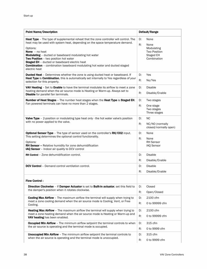
Heat Type
Options:
– The type of supplemental reheat that the zone controller will control. The heat may be used with system heat, depending on the space temperature demand.
None – no heat Modulating – ducted or baseboard modulating hot water Two Position – two position hot water Staged EH – ducted or baseboard electric heat Combination
D:
– combination baseboard modulating hot water and ducted staged electric heat
R:
None
None Modulating Two Position Staged EH Combination
Ducted Heat – Determines whether the zone is using ducted heat or baseboard. If Heat Type is Combination
D: , this is automatically set internally to Yes regardless of your
selection for this property. R:
Yes
No/Yes
VAV Heating – Set to Enable to have the terminal modulate its airflow to meet a zone heating demand when the air source mode is Heating or Warm-up. Always set to Disable
D:
for parallel fan terminals. R:
Disable
Disable/Enable
Number of Heat Stages – The number heat stages when the Heat Type is Staged EH D: . Fan powered terminals can have no more than 2 stages.
R:
Two stages
One stage Two stages Three stages
Valve Type D: – 2-position or modulating type heat only - the hot water valve's position with no power applied to the valve.
R:
NC
NC/NO (normally closed/normally open)
Optional Sensor Type – The type of sensor used on the controller's RH/CO2
Options:
input. This setting determines the optional control functionality.
RH Sensor – Relative humidity for zone dehumidification IAQ Sensor
D:
– Indoor air quality to DCV control
R:
None
None RH Sensor IAQ Sensor
RH Control D: – Zone dehumidification control.
R:
Disable
Disable/Enable
DCV Control D: – Demand control ventilation control.
R:
Disable
Disable/Enable
Flow Control :
Direction Clockwise – If Damper Actuator is set to Built-in actuator D: , set this field to the damper's position when it rotates clockwise.
R:
Closed
Open/Closed
Cooling Max Airflow D: – The maximum airflow the terminal will supply when trying to meet a zone cooling demand when the air source mode is Cooling, Vent, or Free Cooling. R:
2100 cfm
0 to 99999 cfm
Heating Max Airflow – The maximum airflow the terminal will supply when trying to meet a zone heating demand when the air source mode is Heating or Warm-up and VAV heating
D:
has been enabled. R:
2100 cfm
0 to 99999 cfm
Occupied Min Airflow D: – The minimum airflow setpoint the terminal controls to when the air source is operating and the terminal mode is occupied.
R:
315 cfm
0 to 9999 cfm
Unoccupied Min Airflow D: – The minimum airflow setpoint the terminal controls to when the air source is operating and the terminal mode is unoccupied.
R:
315 cfm
0 to 9999 cfm
VAV Zone Controllers 39
Point Name/Description
Default/Range
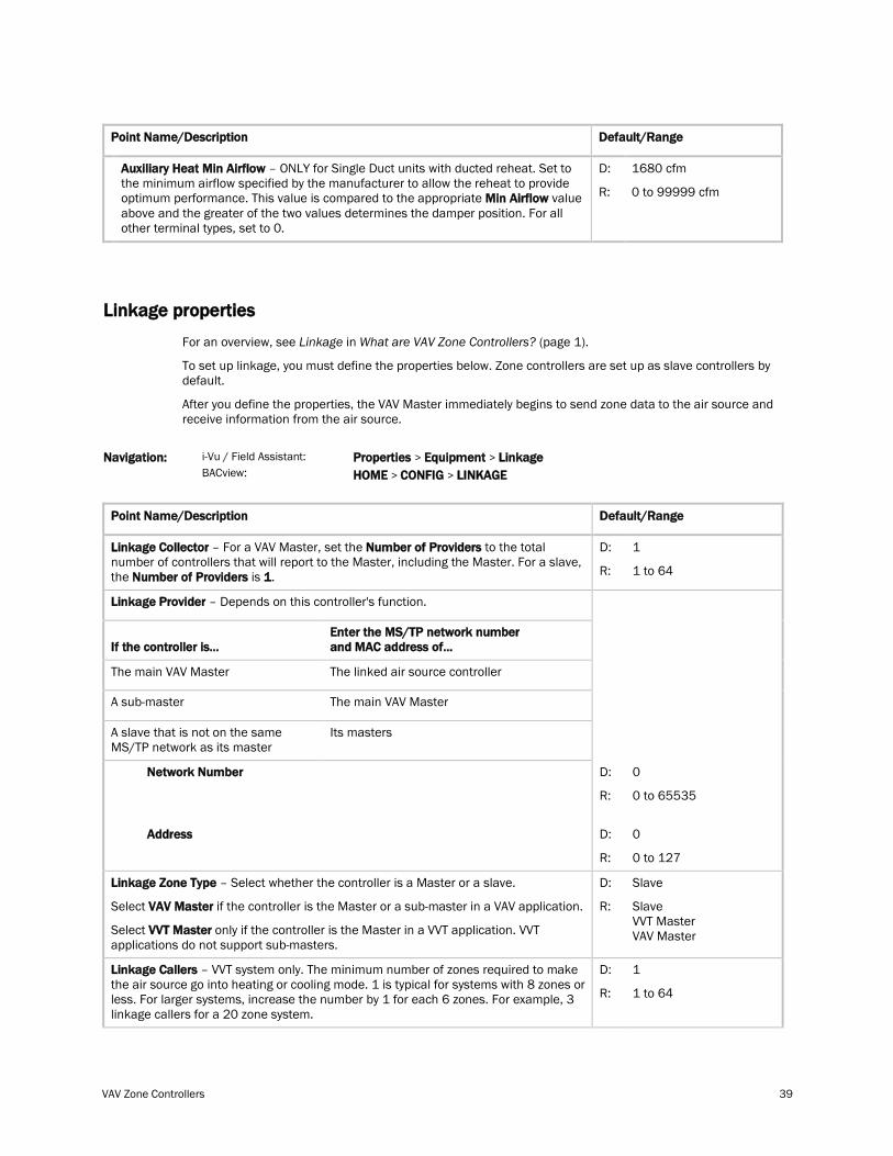
Auxiliary Heat Min Airflow – ONLY for Single Duct units with ducted reheat. Set to the minimum airflow specified by the manufacturer to allow the reheat to provide optimum performance. This value is compared to the appropriate Min Airflow
D:
value above and the greater of the two values determines the damper position. For all other terminal types, set to 0.
R:
1680 cfm
0 to 99999 cfm
Linkage properties
For an overview, see Linkage in What are VAV Zone Controllers? (page 1).
To set up linkage, you must define the properties below. Zone controllers are set up as slave controllers by default.
After you define the properties, the VAV Master immediately begins to send zone data to the air source and receive information from the air source.
i-Vu / Field Assistant: Navigation: BACview:
Properties > Equipment > Linkage HOME > CONFIG >
LINKAGE
Point Name/Description Default/Range
Linkage Collector – For a VAV Master, set the Number of Providers to the total number of controllers that will report to the Master, including the Master. For a slave, the Number of Providers is 1
D:
. R:
1
1 to 64
Linkage Provider – Depends on this controller's function.
If the controller is...
Enter the MS/TP network number and MAC address of...
The main VAV Master The linked air source controller
A sub-master The main VAV Master
A slave that is not on the same MS/TP network as its master
Its masters
Network Number
D:
Address
R:
D:
R:
0
0 to 65535
0
0 to 127
Linkage Zone Type
Select
– Select whether the controller is a Master or a slave.
VAV Master
Select
if the controller is the Master or a sub-master in a VAV application.
VVT Master
D:
only if the controller is the Master in a VVT application. VVT applications do not support sub-masters.
R:
Slave
Slave VVT Master VAV Master
Linkage Callers D: – VVT system only. The minimum number of zones required to make the air source go into heating or cooling mode. 1 is typical for systems with 8 zones or less. For larger systems, increase the number by 1 for each 6 zones. For example, 3 linkage callers for a 20 zone system.
R:
1
1 to 64
Start-up
40 VAV Zone Controllers
Point Name/Description Default/Range
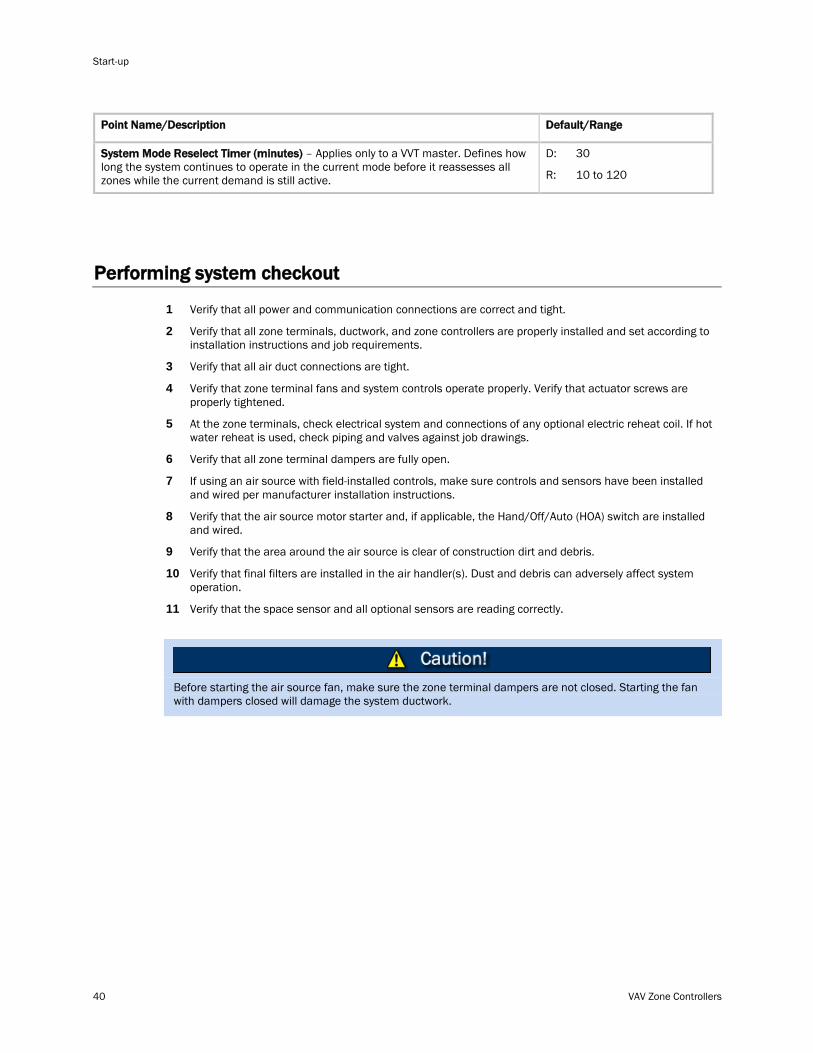
System Mode Reselect Timer (minutes) D: – Applies only to a VVT master. Defines how long the system continues to operate in the current mode before it reassesses all zones while the current demand is still active. R:
30
10 to 120
Performing system checkout
1 Verify that all power and communication connections are correct and tight.
2 Verify that all zone terminals, ductwork, and zone controllers are properly installed and set according to installation instructions and job requirements.
3 Verify that all air duct connections are tight.
4 Verify that zone terminal fans and system controls operate properly. Verify that actuator screws are properly tightened.
5 At the zone terminals, check electrical system and connections of any optional electric reheat coil. If hot water reheat is used, check piping and valves against job drawings.
6 Verify that all zone terminal dampers are fully open.
7 If using an air source with field-installed controls, make sure controls and sensors have been installed and wired per manufacturer installation instructions.
8 Verify that the air source motor starter and, if applicable, the Hand/Off/Auto (HOA) switch are installed and wired.
9 Verify that the area around the air source is clear of construction dirt and debris.
10 Verify that final filters are installed in the air handler(s). Dust and debris can adversely affect system operation.
11 Verify that the space sensor and all optional sensors are reading correctly.
Before starting the air source fan, make sure the zone terminal dampers are not closed. Starting the fan with dampers closed will damage the system ductwork.
VAV Zone Controllers 41
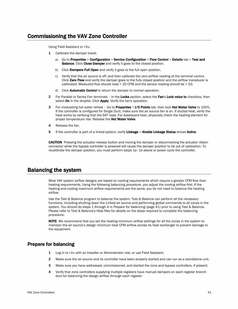
Commissioning the VAV Zone Controller
Using Field Assistant or i-Vu:
1 Calibrate the damper travel.
a) Go to Properties > Configuration > Service Configuration > Flow Control > Details tab > Test and Balance. Click Close Damper
b) Click
and verify it goes to the closed position.
Dampers Full Open
c) Verify that the air source is off, and then calibrate the zero airflow reading at the terminal control. Click
and verify it goes to the full open position.
Zero Flow
d) Click
and verify the damper goes to the fully closed position and the airflow transducer is calibrated. Measured flow should read < 20 CFM and the sensor reading should be < 03.
Automatic Control
2 For Parallel or Series Fan terminals – In the Locks section, select the Fan's Lock value to checkbox, then select On in the droplist. Click Apply. Verify the fan's operation.
to return the damper to normal operation.
3 For modulating hot water reheat – Go to Properties > I/O Points tab, then lock Hot Water Valve to 100%. If the controller is configured for Single Duct, make sure the air source fan is on. If ducted heat, verify the heat works by verifying that the SAT rises. For baseboard heat, physically check the heating element for proper temperature rise. Release the Hot Water Valve.
4 Release the fan.
5 If the controller is part of a linked system, verify Linkage > Airside Linkage Status shows Active.
CAUTION Pressing the actuator release button and moving the damper or disconnecting the actuator ribbon connector while the bypass controller is powered will cause the damper position to be out of calibration. To recalibrate the damper position, you must perform steps 1a–1d above or power cycle the controller.
Balancing the system
Most VAV system airflow designs are based on cooling requirements which require a greater CFM flow than heating requirements. Using the following balancing procedure, you adjust the cooling airflow first. If the heating and cooling maximum airflow requirements are the same, you do not need to balance the heating airflow.
Use the Test & Balance program to balance the system. Test & Balance can perform all the necessary functions, including shutting down the Linked air source and performing global commands to all zones in the system. You should do steps 1 through 4 in Prepare for balancing (page 41) prior to using Test & Balance. Please refer to Test & Balance's Help files for details on the steps required to complete the balancing procedure.
NOTE We recommend that you set the heating minimum airflow settings for all the zones in the system to maintain the air source’s design minimum heat CFM airflow across its heat exchanger to prevent damage to the equipment.
Prepare for balancing
1 Log in to i-Vu with an Installer or Administrator role, or use Field Assistant.
2 Make sure the air source and its controller have been properly started and can run as a standalone unit.
3 Make sure you have addressed, commissioned, and started the zone and bypass controllers, if present.
4 Verify that zone controllers supplying multiple registers have manual dampers on each register branch duct for balancing the design airflow through each register.
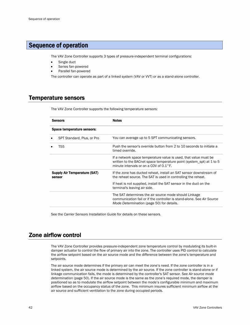
Sequence of operation
42 VAV Zone Controllers
The VAV Zone Controller supports 3 types of pressure-independent terminal configurations: • Single duct • Series fan-powered • Parallel fan-powered The controller can operate as part of a linked system (VAV or VVT) or as a stand-alone controller.
Temperature sensors
The VAV Zone Controller supports the following temperature sensors:
Sensors Notes
Space temperature sensors:
• SPT Standard, Plus, or Pro You can average up to 5 SPT communicating sensors.
• T55 Push the sensor's override button from 2 to 10 seconds to initiate a timed override.
If a network space temperature value is used, that value must be written to the BACnet space temperature point (system_spt) at 1 to 5 minute intervals or on a COV of 0.1°F.
If the zone has ducted reheat, install an SAT sensor downstream of the reheat source. The SAT is used in controlling the reheat.
Supply Air Temperature (SAT) sensor
If heat is not supplied, install the SAT sensor in the duct on the terminal's leaving air side.
The SAT determines the air source mode should Linkage communication fail or if the controller is stand-alone. See Air Source Mode Determination 50 (page ) for details.
See the Carrier Sensors Installation Guide for details on these sensors.
Zone airflow control
The VAV Zone Controller provides pressure-independent zone temperature control by modulating its built-in damper actuator to control the flow of primary air into the zone. The controller uses PID control to calculate the airflow setpoint based on the air source mode and the difference between the zone’s temperature and setpoints.
The air source mode determines if the primary air can meet the zone’s need. If the zone controller is in a linked system, the air source mode is determined by the air source. If the zone controller is stand-alone or if linkage communication fails, the mode is determined by the controller's SAT sensor. See Air source mode determination (page 50). If the air source mode is the same as the zone’s required mode, the damper is positioned so as to modulate the airflow setpoint between the mode’s configurable minimum and maximum airflow based on the occupancy status of the zone. This minimum insures sufficient minimum airflow at the air source and sufficient ventilation to the zone during occupied periods.
Sequence of operation
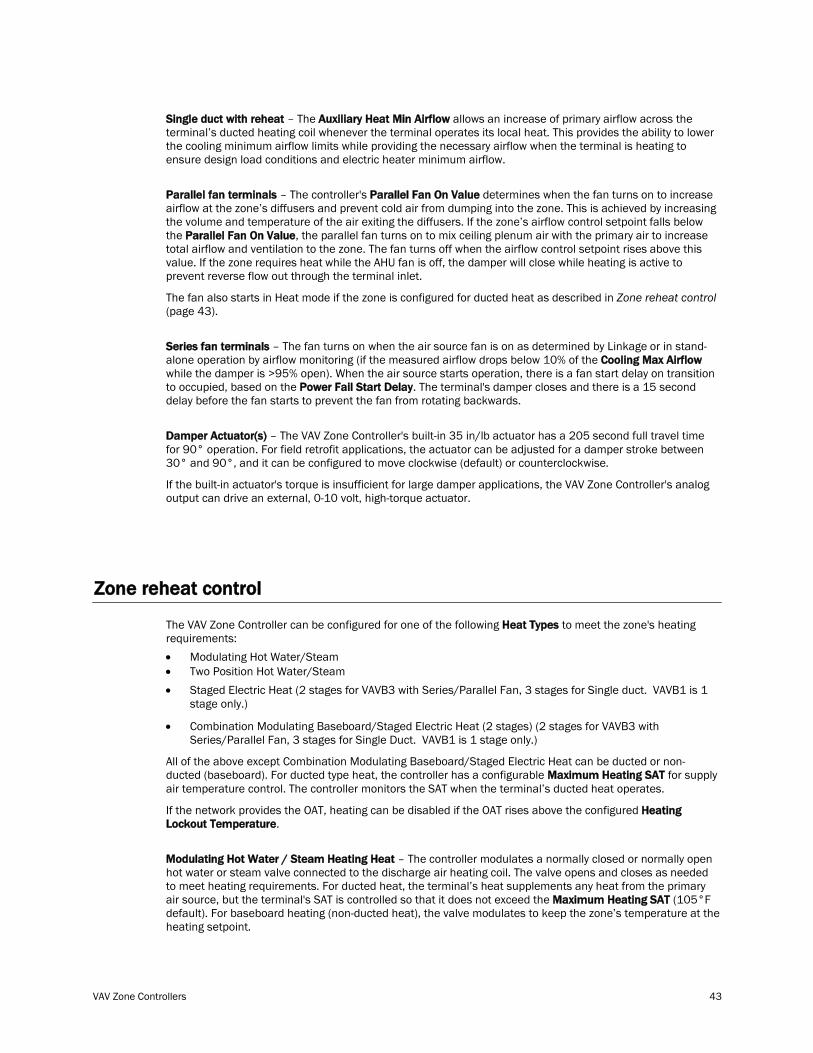
VAV Zone Controllers 43
Single duct with reheat – The Auxiliary Heat Min Airflow allows an increase of primary airflow across the terminal’s ducted heating coil whenever the terminal operates its local heat. This provides the ability to lower the cooling minimum airflow limits while providing the necessary airflow when the terminal is heating to ensure design load conditions and electric heater minimum airflow.
Parallel fan terminals – The controller's Parallel Fan On Value determines when the fan turns on to increase airflow at the zone’s diffusers and prevent cold air from dumping into the zone. This is achieved by increasing the volume and temperature of the air exiting the diffusers. If the zone’s airflow control setpoint falls below the Parallel Fan On Value, the parallel fan turns on to mix ceiling plenum air with the primary air to increase total airflow and ventilation to the zone. The fan turns off when the airflow control setpoint rises above this value. If the zone requires heat while the AHU fan is off, the damper will close while heating is active to prevent reverse flow out through the terminal inlet.
The fan also starts in Heat mode if the zone is configured for ducted heat as described in Zone reheat control (page 43).
Series fan terminals – The fan turns on when the air source fan is on as determined by Linkage or in stand-alone operation by airflow monitoring (if the measured airflow drops below 10% of the Cooling Max Airflow while the damper is >95% open). When the air source starts operation, there is a fan start delay on transition to occupied, based on the Power Fail Start Delay. The terminal's damper closes and there is a 15 second delay before the fan starts to prevent the fan from rotating backwards.
Damper Actuator(s) – The VAV Zone Controller's built-in 35 in/lb actuator has a 205 second full travel time for 90° operation. For field retrofit applications, the actuator can be adjusted for a damper stroke between 30° and 90°, and it can be configured to move clockwise (default) or counterclockwise.
If the built-in actuator's torque is insufficient for large damper applications, the VAV Zone Controller's analog output can drive an external, 0-10 volt, high-torque actuator.
Zone reheat control
The VAV Zone Controller can be configured for one of the following Heat Types to meet the zone's heating requirements: • Modulating Hot Water/Steam • Two Position Hot Water/Steam • Staged Electric Heat (2 stages for VAVB3 with Series/Parallel Fan, 3 stages for Single duct. VAVB1 is 1
stage only.)
• Combination Modulating Baseboard/Staged Electric Heat (2 stages) (2 stages for VAVB3 with Series/Parallel Fan, 3 stages for Single Duct. VAVB1 is 1 stage only.)
All of the above except Combination Modulating Baseboard/Staged Electric Heat can be ducted or non-ducted (baseboard). For ducted type heat, the controller has a configurable Maximum Heating SAT for supply air temperature control. The controller monitors the SAT when the terminal’s ducted heat operates.
If the network provides the OAT, heating can be disabled if the OAT rises above the configured Heating Lockout Temperature.
Modulating Hot Water / Steam Heating Heat – The controller modulates a normally closed or normally open hot water or steam valve connected to the discharge air heating coil. The valve opens and closes as needed to meet heating requirements. For ducted heat, the terminal’s heat supplements any heat from the primary air source, but the terminal's SAT is controlled so that it does not exceed the Maximum Heating SAT (105°F default). For baseboard heating (non-ducted heat), the valve modulates to keep the zone’s temperature at the heating setpoint.
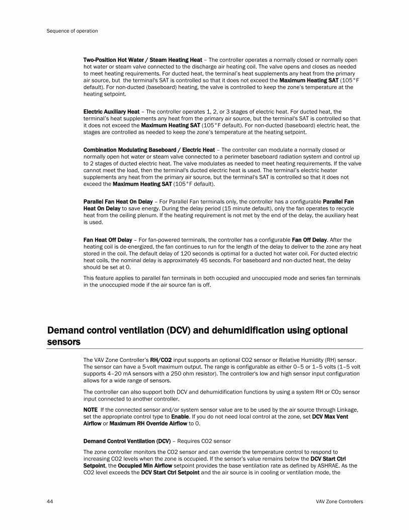
Sequence of operation
44 VAV Zone Controllers
Two-Position Hot Water / Steam Heating Heat – The controller operates a normally closed or normally open hot water or steam valve connected to the discharge air heating coil. The valve opens and closes as needed to meet heating requirements. For ducted heat, the terminal’s heat supplements any heat from the primary air source, but the terminal's SAT is controlled so that it does not exceed the Maximum Heating SAT (105°F default). For non-ducted (baseboard) heating, the valve is controlled to keep the zone’s temperature at the heating setpoint.
Electric Auxiliary Heat – The controller operates 1, 2, or 3 stages of electric heat. For ducted heat, the terminal’s heat supplements any heat from the primary air source, but the terminal's SAT is controlled so that it does not exceed the Maximum Heating SAT (105°F default). For non-ducted (baseboard) electric heat, the stages are controlled as needed to keep the zone’s temperature at the heating setpoint.
Combination Modulating Baseboard / Electric Heat – The controller can modulate a normally closed or normally open hot water or steam valve connected to a perimeter baseboard radiation system and control up to 2 stages of ducted electric heat. The valve modulates as needed to meet heating requirements. If the valve cannot meet the load, then the terminal's ducted electric heat is used. The terminal’s electric heater supplements any heat from the primary air source, but the terminal's SAT is controlled so that it does not exceed the Maximum Heating SAT (105°F default).
Parallel Fan Heat On Delay – For Parallel Fan terminals only, the controller has a configurable Parallel Fan Heat On Delay to save energy. During the delay period (15 minute default), only the fan operates to recycle heat from the ceiling plenum. If the heating requirement is not met by the end of the delay, the auxiliary heat is used.
Fan Heat Off Delay – For fan-powered terminals, the controller has a configurable Fan Off Delay. After the heating coil is de-energized, the fan continues to run for the length of the delay to deliver to the zone any heat stored in the coil. The default delay of 120 seconds is optimal for a ducted hot water coil. For ducted electric heat coils, the nominal delay is approximately 45 seconds. For baseboard and non-ducted heat, the delay should be set at 0.
This feature applies to parallel fan terminals in both occupied and unoccupied mode and series fan terminals in the unoccupied mode if the air source fan is off.
Demand control ventilation (DCV) and dehumidification using optional sensors
The VAV Zone Controller’s RH/CO2 input supports an optional CO2 sensor or Relative Humidity (RH) sensor. The sensor can have a 5-volt maximum output. The range is configurable as either 0–5 or 1–5 volts (1–5 volt supports 4–20 mA sensors with a 250 ohm resistor). The controller's low and high sensor input configuration allows for a wide range of sensors.
The controller can also support both DCV and dehumidification functions by using a system RH or CO2 sensor input connected to another controller.
NOTE If the connected sensor and/or system sensor value are to be used by the air source through Linkage, set the appropriate control type to Enable. If you do not need local control at the zone, set DCV Max Vent Airflow or Maximum RH Override Airflow to 0.
Demand Control Ventilation (DCV) – Requires CO2 sensor
The zone controller monitors the CO2 sensor and can override the temperature control to respond to increasing CO2 levels when the zone is occupied. If the sensor’s value remains below the DCV Start Ctrl Setpoint, the Occupied Min Airflow setpoint provides the base ventilation rate as defined by ASHRAE. As the CO2 level exceeds the DCV Start Ctrl Setpoint and the air source is in cooling or ventilation mode, the
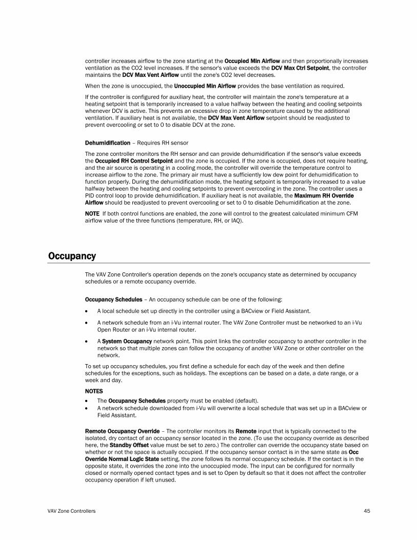
VAV Zone Controllers 45
controller increases airflow to the zone starting at the Occupied Min Airflow and then proportionally increases ventilation as the CO2 level increases. If the sensor's value exceeds the DCV Max Ctrl Setpoint, the controller maintains the DCV Max Vent Airflow until the zone's CO2 level decreases.
When the zone is unoccupied, the Unoccupied Min Airflow provides the base ventilation as required.
If the controller is configured for auxiliary heat, the controller will maintain the zone's temperature at a heating setpoint that is temporarily increased to a value halfway between the heating and cooling setpoints whenever DCV is active. This prevents an excessive drop in zone temperature caused by the additional ventilation. If auxiliary heat is not available, the DCV Max Vent Airflow setpoint should be readjusted to prevent overcooling or set to 0 to disable DCV at the zone.
Dehumidification – Requires RH sensor
The zone controller monitors the RH sensor and can provide dehumidification if the sensor's value exceeds the Occupied RH Control Setpoint and the zone is occupied. If the zone is occupied, does not require heating, and the air source is operating in a cooling mode, the controller will override the temperature control to increase airflow to the zone. The primary air must have a sufficiently low dew point for dehumidification to function properly. During the dehumidification mode, the heating setpoint is temporarily increased to a value halfway between the heating and cooling setpoints to prevent overcooling in the zone. The controller uses a PID control loop to provide dehumidification. If auxiliary heat is not available, the Maximum RH Override Airflow should be readjusted to prevent overcooling or set to 0 to disable Dehumidification at the zone.
NOTE If both control functions are enabled, the zone will control to the greatest calculated minimum CFM airflow value of the three functions (temperature, RH, or IAQ).
Occupancy
The VAV Zone Controller's operation depends on the zone's occupancy state as determined by occupancy schedules or a remote occupancy override.
Occupancy Schedules – An occupancy schedule can be one of the following:
• A local schedule set up directly in the controller using a BACview or Field Assistant.
• A network schedule from an i-Vu internal router. The VAV Zone Controller must be networked to an i-Vu Open Router or an i-Vu internal router.
• A System Occupancy network point. This point links the controller occupancy to another controller in the network so that multiple zones can follow the occupancy of another VAV Zone or other controller on the network.
To set up occupancy schedules, you first define a schedule for each day of the week and then define schedules for the exceptions, such as holidays. The exceptions can be based on a date, a date range, or a week and day.
NOTES • The Occupancy Schedules• A network schedule downloaded from i-Vu will overwrite a local schedule that was set up in a BACview or
Field Assistant.
property must be enabled (default).
Remote Occupancy Override – The controller monitors its Remote input that is typically connected to the isolated, dry contact of an occupancy sensor located in the zone. (To use the occupancy override as described here, the Standby Offset value must be set to zero.) The controller can override the occupancy state based on whether or not the space is actually occupied. If the occupancy sensor contact is in the same state as Occ Override Normal Logic State setting, the zone follows its normal occupancy schedule. If the contact is in the opposite state, it overrides the zone into the unoccupied mode. The input can be configured for normally closed or normally opened contact types and is set to Open by default so that it does not affect the controller occupancy operation if left unused.
Sequence of operation
46 VAV Zone Controllers
The Remote input can also be used to expand the setpoints during occupied periods without affecting the occupancy status of the zone. Whenever the zone is occupied and the Remote input senses the occupant has left the zone, if a value greater than zero has been entered for the Standby Offset, then the occupied setpoints will be expanded by that number of degrees. This provides the ability to save energy but recover more rapidly rather than having the zone go unoccupied.
Learning Adaptive Optimal Start – This function gradually adjusts the unoccupied setpoints over a specified period of time to achieve the occupied setpoint by the time scheduled occupancy begins. This learning adaptive algorithm uses the learned heating capacity and learned cooling capacity values to calculate the effective setpoints prior to the occupied start time. The algorithm calculates a learned cooling and heating capacity during the previous unoccupied time. Set the Learning Adaptive Optimal Start recovery period from 1 to 4 hours in Optimal Start. When the Learning Adaptive Optimal Start routine runs, adjustments are based on the color that is achieved when occupancy begins. Adjustment amounts are defined in the thermographic color fields located directly above the Effective Set Points graph under Setpoints.
BAS On/Off – This function allows third party control of the controller occupancy. Occupancy Schedules must be set to Disable to use this function. When set to Occupied or Unoccupied, Optimal Start is automatically disabled.
Alarms
Space Temp Sensor Alarm – The VAV Zone Controller monitors each space temperature sensor and the network input for space temperature. If no valid space temperature value is available, the controller generates an alarm and disables all local heating or cooling. The controller modulates the damper to the minimum heat, minimum cool, or ventilation position based on the air source mode. Normal operation resumes when the controller detects a valid sensor value.
Space Temperature Alarm – The controller generates an alarm if the space temperature exceeds the alarm setpoint. The occupied alarm setpoints are determined from the configurable Occupied Alarm Hysteresis (5°F default) which is subtracted from the configured occupied heat and added to the configured occupied cool setpoints. If the space temperature rises above or falls below this value and the condition lasts for more than 15 minutes, an alarm is generated. The configurable unoccupied high and low alarm setpoints have a fixed 10 minute alarm delay. When a transition from unoccupied to occupied occurs or the occupied temperature setpoints are changed causing an immediate alarm condition, the controller automatically calculates an additional alarm delay equal to 10 minutes for each degree of change. This additional delay is added to the 15 minute fixed delay and allows the space temperature to recover and achieve the new setpoints, preventing unnecessary alarms. The space temperature alarm returns to normal when the space temperature again falls between the current mode’s alarm setpoints.
Supply Air Temperature Alarm – The controller generates an alarm if the SAT exceeds the configured High SAT Alarm Limit (120°F default) or falls below the Low SAT Alarm Limit (45°F default) for more than 5 minutes. The hysteresis for return to normal is 1°F. The High SAT Alarm Limit should be set to a value at least 15 degrees F above the Maximum Heating SAT or the maximum discharge temperature from the air source, whichever is greater.
Space Relative Humidity Alarm – If Optional Ctrl Type is set to RH Control (Space Relative Humidity (RH) sensor is installed), the controller generates an alarm if the sensor's value exceeds the Occ High RH Alarm Limit (100% rh default) or the Unocc High RH Alarm Limit (100% rh default). The controller provides a 30-minute alarm delay during unoccupied periods. During occupied periods, the controller uses the Occ High RH Alarm Limit. When a transition from unoccupied to occupied occurs or the occupied high alarm limit is lowered causing an alarm condition to occur, the controller automatically calculates an alarm delay equal to 5 minutes for each % RH of change. This additional delay is added to the 15 minute fixed delay and allows the space relative humidity to recover and achieve the new setpoints, preventing unnecessary alarms.
VAV Zone Controllers 47
Indoor Air Quality Alarm – If Optional Ctrl Type is set to IAQ Control (CO2 sensor is installed), the controller generates an alarm during occupied periods if the sensor's value exceeds the Occupied High CO2 Alarm Limit. When a transition from unoccupied to occupied occurs, or if the occupied alarm limit is changed to a value that causes an alarm condition to occur, the controller automatically calculates an alarm delay equal to 15 seconds for each ppm of change based on the error from setpoint (15 minutes minimum, 4 hours maximum). This delay prevents unnecessary alarms and gives the zone time to correct the alarm condition. To disable the IAQ alarm, set Occupied High CO2 Alarm Limit to 0. The default value is 1100ppm. The hysteresis for return to normal is 100ppm.
Filter Alarm – For series or parallel fan-powered terminals, the controller monitors the accumulated hours of fan operation and generates an alarm when accumulated hours exceed the configured Filter Service Alarm Timer limit. The default value is 0 hours which disables the alarm. The alarm can be reset by setting Reset Filter Alarm to On or resetting the configured alarm limit to 0 hours.
Airside Linkage Alarm – The slave zone controller generates an alarm if it has once been linked successfully to a master zone and then it fails to receive linkage information for 5 minutes. If the controller is the VVT Master, it generates an alarm if it does not communicate with its air source for 5 minutes after having been previously communicating successfully. A return-to-normal is generated after successful Linkage communication resumes. A power cycle will reset and re-initialize the Airside Linkage Alarm.
Demand limiting
Demand limiting is a cost-saving strategy to reduce energy consumption. The strategy expands the setpoints when the system reaches one of 3 levels of consumption. With the expanded setpoints, the equipment works less, thereby saving energy.
If the VAV Zone Controller receives a demand limit signal through the network, it expands its setpoints based on the demand level. The default amount is 1°F for demand level 1, 2°F for demand level 2, or 4°F for demand level 3.
Linkage
The i-Vu Open Control System uses linkage to exchange data between the zone terminals and their air source to form a coordinated HVAC system. The system's air source controller, zone controllers, and bypass controller (if applicable) are linked so that their data exchange can be managed by one zone controller configured as the Master.
The basic linkage process is as follows:
1 The Master gathers data from the slave zone controllers such as occupancy status, setpoints, and zone temperature.
2 The Master performs mathematical calculations and algorithms on the data.
3 The Master sends the composite information to the air source.
4 The air source returns information such as mode, supply air temperature, and outside air temperature, if present.
5 The Master passes that information to all slave zone controllers.
Sequence of operation
48 VAV Zone Controllers
The following sections detail the process for VAV Systems and VVT Systems.
VAV Systems The VAV Master continuously scans the system and gathers the following information from each zone: • Setpoints and zone temperature • Zone size • Occupancy status • Damper position • RH and CO2
The VAV Master then does the following calculations and sends the results to the air source.
values (if applicable)
• If any zone is occupied, the system's occupancy status is set to occupied.
• If the system is occupied, it averages the space temperatures from all occupied zones using their normal terminal size at 1" VP to apply a weighting factor to that average (OCCSPT).
• If no zone is occupied, it sets the occupied space temperature to “?“ .
• It performs this same weighted average space temperature calculation for all the zones in the system (SPT).
• It calculates four weighted average setpoints: • the occupied heating weighted average setpoint (OHSP) • occupied cooling weighted average setpoint (OCSP) • the weighted average unoccupied heating setpoint (UHSP) • unoccupied cooling setpoint (UCSP).
• If the zones supply CO2 or RH values, it calculates either a maximum or average value as determined by the configuration for each.
The air source determines its operating mode from the information received, and then sends the following to the Master: • Air source mode • Supply air temperature • Outside air temperature • Static pressure (if applicable) The air source verifies the mode by comparing its supply air temperature to the space temperature received through linkage. See the air source documentation for operation and parameters used to verify its mode. This verification allows the system to verify that the stated air source mode is actually being provided. For example, if the air source heat has failed, the air source's actual mode would not indicate heat unless that mode was verified by the equipment’s supply air temperature.
The VAV Master continuously evaluates all zones and processes their data as described above. The system switches modes only if the equipment mode changes.
VAV Zone Controllers 49
VVT Systems A VVT Master determines system operation by prioritizing heating and cooling requirements from all the zones based on their occupancy, demand, and damper size.
The VVT Master continuously scans the system to determine if any zones are occupied. If any zones are occupied, the VVT Master evaluates the occupied zones' heating or cooling demands to determine the following:
• The system mode. The mode is:
○ Cooling if the number of occupied zones with cooling demands exceeds the number of occupied zones with heating demands, and the demand is greater than or equal to the number of configured Linkage Callers.
○ Heating if the number of occupied zones with a heating demand exceeds or is equal to the number of Linkage Callers.
• The reference zone, the zone with the greatest demand for the system mode
If no zones are occupied or no occupied zones require heating or cooling, the VVT Master performs the evaluation described above for the unoccupied zones.
The VVT Master then sends the following information to the air source: • The setpoints and zone temperature from the zone with the reference zone • The system occupancy status • Most open damper position from any zone • RH and CO2
The air source then sends to the VVT Master: values (if applicable)
• The air source mode • Supply air temperature • Outside air temperature (if applicable) • Static pressure (if applicable) The air source verifies the mode by comparing its supply air temperature to the space temperature received through Linkage. See the air source documentation for operation and parameters used to verify its mode. This verification determines if the desired air source mode is being provided. For example, if the VVT Master requests heating but the air source does not have heat or its heat has failed, the verification indicates this. The actual current mode is sent to the zones so that they can control accordingly.
The system remains in that mode until all zones of that demand are satisfied or until a fixed 30 minute mode reselect timer causes a forced re-evaluation of the system. If there is no demand for the opposite mode or the demand is smaller than the current mode, the reselect timer is reset to 30 and the current mode continues until all zones are satisfied or until the reselect timer expires, repeating the process. If there is a demand for the opposite mode, the VVT Master sends the new reference zone's space temperature and setpoints for the opposite mode to the air source and restarts the reselect timer. The air source re-evaluates this data and then attempts to provide the air required by the new information. The amount of time it takes to switch modes is determined by the air source’s operating parameters.
The VVT Master continuously evaluates the system and updates the air source with the most current system demand. Based on the evaluation, the reference zone can change from one zone to another. The evaluation process continues until there is no demand from any zone or the 30 minute timer causes a re-evaluation of the system conditions.
If no heating or cooling is required or the current air source mode is satisfied, the VVT Master calculates:
• The weighted average of the occupied and unoccupied heating and cooling setpoints
• A zone temperature that is midway between the setpoints (occupied or unoccupied based on the system’s current occupancy status).
This information, plus the occupancy status, is sent to the air source so that its current mode is disabled and the unit ceases heating or cooling operation. If the system is occupied, the air source fan and OA damper, if applicable, operate to maintain proper ventilation.
Sequence of operation
50 VAV Zone Controllers
Air source mode determination
Linked air source modes – In a linked system, the air source determines its operating mode and qualifies that mode based on its own SAT. The following modes can be sent by the air source depending on its capability and configuration:
• OFF – Air source fan is off.
• WARMUP – Air source fan is on and providing first cycle of heat when changing from unoccupied to occupied.
• HEAT – Air source fan is on and providing heat.
• FREECOOL – Air source fan is on, providing cooling using economizer only, and system is unoccupied.
• COOL – Air source fan is on, and cooling is provided by economizer and/or mechanical cooling.
• PRESSURIZATION – Fire/Life-safety override mode which causes the air source supply fan to operate, and if equipped, the OA damper to provide 100% outside air. Mechanical heating and cooling may be disabled. Any linked terminal will open its primary air damper to provide the configured maximum cooling airflow.
• EVACUATION/SHUTDOWN – Fire/Life-safety override mode which causes the air source supply fan to stop, the return fan to operate, and if equipped, the exhaust air damper to open 100%. Any linked terminal will fully close its primary air damper and disable its terminal fans, if equipped.
• VENT – Air source fan is on, economizer providing ventilation without any mechanical heating or cooling and providing neutral supply air temperature.
See the air source’s installation manual for more specific operation.
Local air source modes – If the zone controller is stand-alone or if linkage communication fails, the zone controller monitors the CFM for fan status and its SAT sensor to determine if the primary air source is providing heating, cooling, or recirculating air in a fan-only or ventilation mode.
• HEAT – For Series or Parallel Fan controllers when the zone terminal fan is off or for single duct controllers: The zone’s local heat has not operated for at least 5 minutes, and the SAT is more than 5°F warmer than the space temperature. If the terminal fan is on, the SAT must be more than 8°F warmer than the space temperature. In all cases, Heat mode is maintained until the SAT drops 2°F below the space temperature.
• VENT – The zone’s local heat has not operated for at least 5 minutes and the SAT is between 65 and 80°F.
• COOL – The zone’s local heat has not operated for at least 5 minutes, the current mode is not Heat, and the SAT is less than 65°F.
• FAN STATUS - Airflow is used determine if the fan is on or off. If the Damper Positions is greater than 95% and the CFM is less than 10% of Nominal CFM at 1” Velocity Pressure for 1 minute and the CFM Setpoint is not equal to 0, then the fan is determined to be off. If CFM is greater than 20% of the Max Cool CFM or greater than 50% of Nominal CFM at 1” Velocity Pressure for 10 seconds (whichever is greater), then the fan is determined to be on. Occupied/Unoccupied Min CFM must be set for greater than 10% of Max Cool CFM.
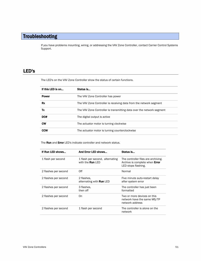
VAV Zone Controllers 51
If you have problems mounting, wiring, or addressing the VAV Zone Controller, contact Carrier Control Systems Support.
LED's
The LED's on the VAV Zone Controller show the status of certain functions.
If this LED is on... Status is...
The VAV Zone Controller has power Power
The VAV Zone Controller is receiving data from the network segment Rx
The VAV Zone Controller is transmitting data over the network segment Tx
The digital output is active DO#
The actuator motor is turning clockwise CW
The actuator motor is turning counterclockwise CCW
The Run and Error LED's indicate controller and network status.
If Run LED shows... And Error LED shows...
1 flash per second
Status is...
1 flash per second, alternating with the Run
The controller files are archiving. Archive is complete when LED Error
2 flashes per second
LED stops flashing.
Off Normal
2 flashes per second 2 flashes, alternating with Run
Five minute auto-restart delay after system error LED
2 flashes per second 3 flashes, then off
The controller has just been formatted
2 flashes per second On Two or more devices on this network have the same MS/TP network address
2 flashes per second 1 flash per second The controller is alone on the network
Troubleshooting
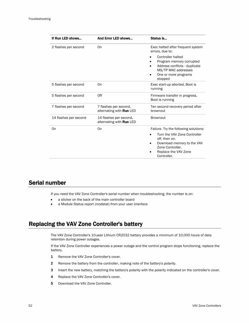
Troubleshooting
52 VAV Zone Controllers
If Run LED shows... And Error LED shows...
2 flashes per second
Status is...
On Exec halted after frequent system errors, due to: • Controller halted • Program memory corrupted • Address conflicts - duplicate
MS/TP MAC addresses • One or more programs
stopped 5 flashes per second On Exec start-up aborted, Boot is
running
5 flashes per second Off Firmware transfer in progress, Boot is running
7 flashes per second 7 flashes per second, alternating with Run
Ten second recovery period after brownout LED
14 flashes per second 14 flashes per second, alternating with Run
Brownout LED
On On Failure. Try the following solutions: • Turn the VAV Zone Controller
off, then on. • Download memory to the VAV
Zone Controller. • Replace the VAV Zone
Controller.
Serial number
If you need the VAV Zone Controller's serial number when troubleshooting, the number is on: • a sticker on the back of the main controller board • a Module Status report (modstat) from your user interface
Replacing the VAV Zone Controller's battery
The VAV Zone Controller's 10-year Lithium CR2032 battery provides a minimum of 10,000 hours of data retention during power outages.
If the VAV Zone Controller experiences a power outage and the control program stops functioning, replace the battery.
1 Remove the VAV Zone Controller's cover.
2 Remove the battery from the controller, making note of the battery's polarity.
3 Insert the new battery, matching the battery's polarity with the polarity indicated on the controller's cover.
4 Replace the VAV Zone Controller's cover.
5 Download the VAV Zone Controller.
VAV Zone Controllers 53
FCC Compliance
This equipment has been tested and found to comply with the limits for a Class A digital device, pursuant to Part 15 of the FCC Rules. These limits are designed to provide reasonable protection against harmful interference when the equipment is operated in a commercial environment. This equipment generates, uses, and can radiate radio frequency energy and, if not installed and used in accordance with the instruction manual, may cause harmful interference to radio communications. Operation of this equipment in a residential area is likely to cause harmful interference in which case the user will be required to correct the interference at his own expense.
CAUTION Changes or modifications not expressly approved by the responsible party for compliance could void the user’s authority to operate the equipment.
CE Compliance
WARNING This is a Class A product. In a domestic environment, this product may cause radio interference in which case the user may be required to take adequate measures.
BACnet Compliance
BACnet® is a registered trademark of ASHRAE. ASHRAE does not endorse, approve or test products for compliance with ASHRAE standards. Compliance of listed products to requirements of ASHRAE Standard 135 is the responsibility of the BACnet manufacturers Association (BMA). BTL® is a registered trademark of the BMA.
Compliance
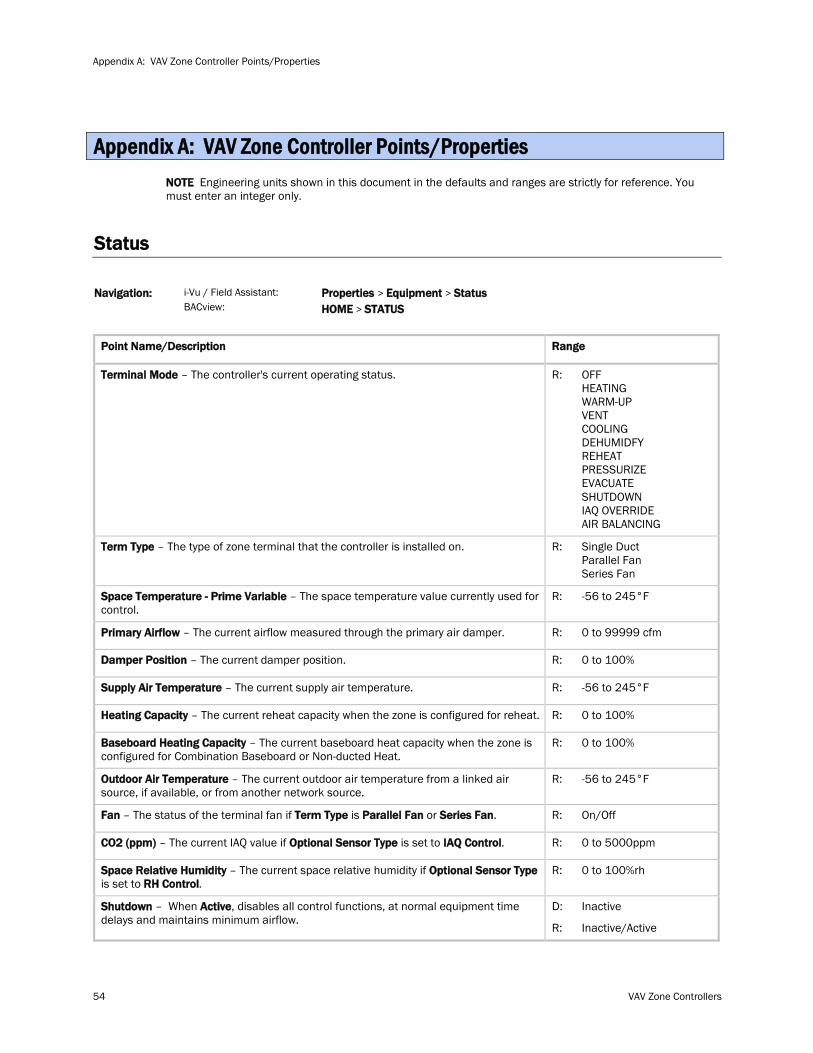
Appendix A: VAV Zone Controller Points/Properties
54 VAV Zone Controllers
NOTE Engineering units shown in this document in the defaults and ranges are strictly for reference. You must enter an integer only.
Status
i-Vu / Field Assistant: Navigation: BACview:
Properties > Equipment > Status HOME >
STATUS
Point Name/Description Range
Terminal Mode R: – The controller's current operating status. OFF HEATING WARM-UP VENT COOLING DEHUMIDFY REHEAT PRESSURIZE EVACUATE SHUTDOWN IAQ OVERRIDE AIR BALANCING
Term Type R: – The type of zone terminal that the controller is installed on. Single Duct Parallel Fan Series Fan
Space Temperature - Prime Variable R: – The space temperature value currently used for control.
-56 to 245°F
Primary Airflow R: – The current airflow measured through the primary air damper. 0 to 99999 cfm
Damper Position R: – The current damper position. 0 to 100%
Supply Air Temperature R: – The current supply air temperature. -56 to 245°F
Heating Capacity R: – The current reheat capacity when the zone is configured for reheat. 0 to 100%
Baseboard Heating Capacity R: – The current baseboard heat capacity when the zone is configured for Combination Baseboard or Non-ducted Heat.
0 to 100%
Outdoor Air Temperature R: – The current outdoor air temperature from a linked air source, if available, or from another network source.
-56 to 245°F
Fan – The status of the terminal fan if Term Type is Parallel Fan or Series Fan R: . On/Off
CO2 (ppm) – The current IAQ value if Optional Sensor Type is set to IAQ Control R: . 0 to 5000ppm
Space Relative Humidity – The current space relative humidity if Optional Sensor Type is set to RH Control
R: .
0 to 100%rh
Shutdown – When Active D: , disables all control functions, at normal equipment time delays and maintains minimum airflow.
R:
Inactive
Inactive/Active
Appendix A: VAV Zone Controller Points/Properties
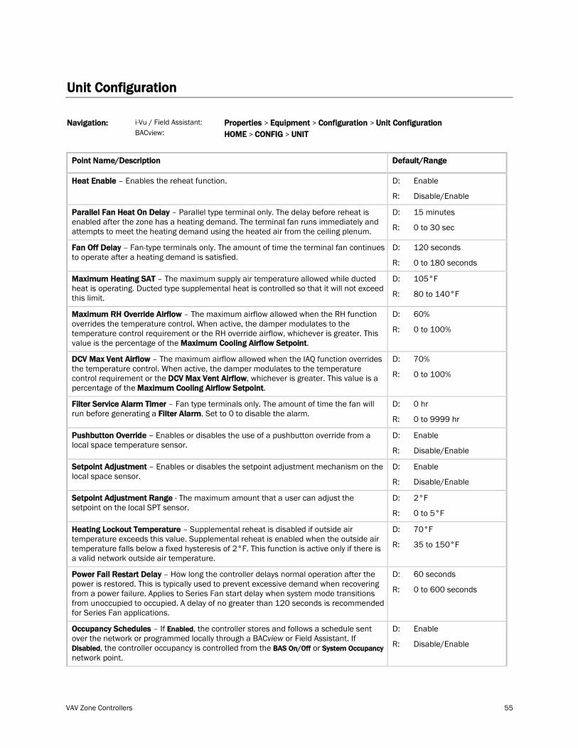
VAV Zone Controllers 55
Unit Configuration
i-Vu / Field Assistant: Navigation: BACview:
Properties > Equipment > Configuration > Unit Configuration HOME > CONFIG >
UNIT
Point Name/Description Default/Range
Heat Enable D: – Enables the reheat function.
R:
Enable
Disable/Enable
Parallel Fan Heat On Delay D: – Parallel type terminal only. The delay before reheat is enabled after the zone has a heating demand. The terminal fan runs immediately and attempts to meet the heating demand using the heated air from the ceiling plenum. R:
15 minutes
0 to 30 sec
Fan Off Delay D: – Fan-type terminals only. The amount of time the terminal fan continues to operate after a heating demand is satisfied.
R:
120 seconds
0 to 180 seconds
Maximum Heating SAT D: – The maximum supply air temperature allowed while ducted heat is operating. Ducted type supplemental heat is controlled so that it will not exceed this limit. R:
105°F
80 to 140°F
Maximum RH Override Airflow – The maximum airflow allowed when the RH function overrides the temperature control. When active, the damper modulates to the temperature control requirement or the RH override airflow, whichever is greater. This value is the percentage of the Maximum Cooling Airflow Setpoint
D:
. R:
60%
0 to 100%
DCV Max Vent Airflow – The maximum airflow allowed when the IAQ function overrides the temperature control. When active, the damper modulates to the temperature control requirement or the DCV Max Vent Airflow, whichever is greater. This value is a percentage of the Maximum Cooling Airflow Setpoint
D:
. R:
70%
0 to 100%
Filter Service Alarm Timer – Fan type terminals only. The amount of time the fan will run before generating a Filter Alarm
D: . Set to 0 to disable the alarm.
R:
0 hr
0 to 9999 hr
Pushbutton Override D: – Enables or disables the use of a pushbutton override from a local space temperature sensor.
R:
Enable
Disable/Enable
Setpoint Adjustment D: – Enables or disables the setpoint adjustment mechanism on the local space sensor.
R:
Enable
Disable/Enable
Setpoint Adjustment Range D: - The maximum amount that a user can adjust the setpoint on the local SPT sensor.
R:
2°F
0 to 5°F
Heating Lockout Temperature D: – Supplemental reheat is disabled if outside air temperature exceeds this value. Supplemental reheat is enabled when the outside air temperature falls below a fixed hysteresis of 2°F. This function is active only if there is a valid network outside air temperature.
R:
70°F
35 to 150°F
Power Fail Restart Delay D: – How long the controller delays normal operation after the power is restored. This is typically used to prevent excessive demand when recovering from a power failure. Applies to Series Fan start delay when system mode transitions from unoccupied to occupied. A delay of no greater than 120 seconds is recommended for Series Fan applications.
R:
60 seconds
0 to 600 seconds
Occupancy Schedules – If Enabled, the controller stores and follows a schedule sent over the network or programmed locally through a BACview or Field Assistant. If Disabled, the controller occupancy is controlled from the BAS On/Off or System Occupancy
D:
network point.
R:
Enable
Disable/Enable
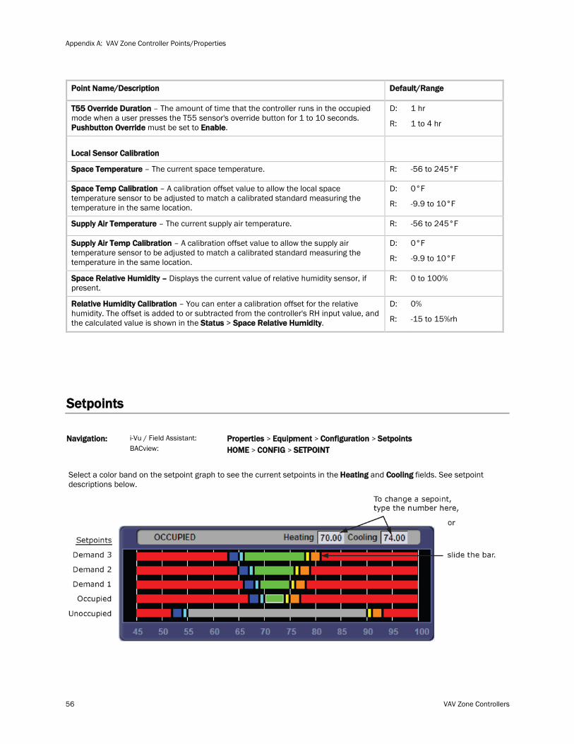
Appendix A: VAV Zone Controller Points/Properties
56 VAV Zone Controllers
Point Name/Description Default/Range
T55 Override Duration – The amount of time that the controller runs in the occupied mode when a user presses the T55 sensor's override button for 1 to 10 seconds. Pushbutton Override must be set to Enable
D:
. R:
1 hr
1 to 4 hr
Local Sensor Calibration
Space Temperature R: – The current space temperature. -56 to 245°F
Space Temp Calibration D: – A calibration offset value to allow the local space temperature sensor to be adjusted to match a calibrated standard measuring the temperature in the same location. R:
0°F
-9.9 to 10°F
Supply Air Temperature R: – The current supply air temperature. -56 to 245°F
Supply Air Temp Calibration D: – A calibration offset value to allow the supply air temperature sensor to be adjusted to match a calibrated standard measuring the temperature in the same location. R:
0°F
-9.9 to 10°F
Space Relative Humidity – R: Displays the current value of relative humidity sensor, if present.
0 to 100%
Relative Humidity Calibration – You can enter a calibration offset for the relative humidity. The offset is added to or subtracted from the controller's RH input value, and the calculated value is shown in the Status > Space Relative Humidity
D:
. R:
0%
-15 to 15%rh
Setpoints
i-Vu / Field Assistant: Navigation: BACview:
Properties > Equipment > Configuration > Setpoints HOME > CONFIG >
SETPOINT
Select a color band on the setpoint graph to see the current setpoints in the Heating and Cooling fields. See setpoint descriptions below.
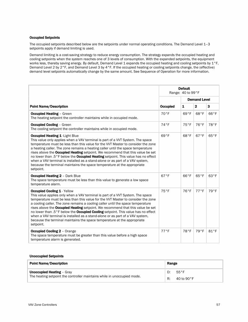
VAV Zone Controllers 57
The occupied setpoints described below are the setpoints under normal operating conditions. The Demand Level 1–3 setpoints apply if demand limiting is used.
Occupied Setpoints
Demand limiting is a cost-saving strategy to reduce energy consumption. The strategy expands the occupied heating and cooling setpoints when the system reaches one of 3 levels of consumption. With the expanded setpoints, the equipment works less, thereby saving energy. By default, Demand Level 1 expands the occupied heating and cooling setpoints by 1°F, Demand Level 2 by 2°F, and Demand Level 3 by 4°F. If the occupied heating or cooling setpoints change, the (effective) demand level setpoints automatically change by the same amount. See Sequence of Operation for more information.
Default Range: 40 to 99°F
Demand Level
Point Name/Description Occupied 1 2 3
Occupied Heating 70°F – Green The heating setpoint the controller maintains while in occupied mode.
69°F 68°F 66°F
Occupied Cooling 74°F – Green The cooling setpoint the controller maintains while in occupied mode.
75°F 76°F 78°F
Occupied Heating 1 -Light Blue This value only applies when a VAV terminal is part of a VVT System. The space temperature must be less than this value for the VVT Master to consider the zone a heating caller. The zone remains a heating caller until the space temperature rises above the Occupied Heating setpoint. We recommend that this value be set no lower than .5°F below the Occupied Heating
69°F
setpoint. This value has no effect when a VAV terminal is installed as a stand-alone or as part of a VAV system, because the terminal maintains the space temperature at the appropriate setpoint.
68°F 67°F 65°F
Occupied Heating 2 67°F – Dark Blue The space temperature must be less than this value to generate a low space temperature alarm.
66°F 65°F 63°F
Occupied Cooling 1 - Yellow This value applies only when a VAV terminal is part of a VVT System. The space temperature must be less than this value for the VVT Master to consider the zone a cooling caller. The zone remains a cooling caller until the space temperature rises above the Occupied Heating setpoint. We recommend that this value be set no lower than .5°F below the Occupied Cooling
75°F
setpoint. This value has no effect when a VAV terminal is installed as a stand-alone or as part of a VAV system, because the terminal maintains the space temperature at the appropriate setpoint.
76°F 77°F 79°F
Occupied Cooling 2 77°F – Orange The space temperature must be greater than this value before a high space temperature alarm is generated.
78°F 79°F 81°F
Unoccupied Setpoints
Point Name/Description Range
Unoccupied Heating D: – Gray The heating setpoint the controller maintains while in unoccupied mode.
R:
55°F
40 to 90°F
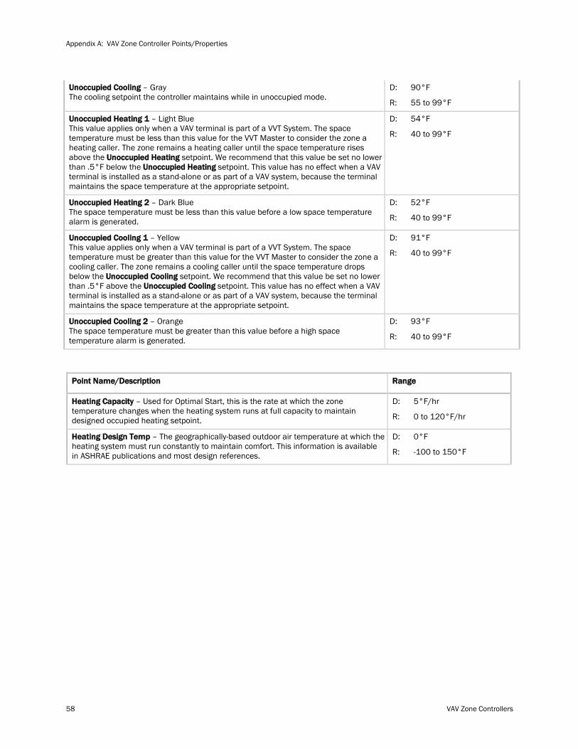
Appendix A: VAV Zone Controller Points/Properties
58 VAV Zone Controllers
Unoccupied Cooling D: – Gray The cooling setpoint the controller maintains while in unoccupied mode.
R:
90°F
55 to 99°F
Unoccupied Heating 1 – Light Blue This value applies only when a VAV terminal is part of a VVT System. The space temperature must be less than this value for the VVT Master to consider the zone a heating caller. The zone remains a heating caller until the space temperature rises above the Unoccupied Heating setpoint. We recommend that this value be set no lower than .5°F below the Unoccupied Heating
D:
setpoint. This value has no effect when a VAV terminal is installed as a stand-alone or as part of a VAV system, because the terminal maintains the space temperature at the appropriate setpoint.
R:
54°F
40 to 99°F
Unoccupied Heating 2 D: – Dark Blue The space temperature must be less than this value before a low space temperature alarm is generated. R:
52°F
40 to 99°F
Unoccupied Cooling 1 – Yellow This value applies only when a VAV terminal is part of a VVT System. The space temperature must be greater than this value for the VVT Master to consider the zone a cooling caller. The zone remains a cooling caller until the space temperature drops below the Unoccupied Cooling setpoint. We recommend that this value be set no lower than .5°F above the Unoccupied Cooling
D:
setpoint. This value has no effect when a VAV terminal is installed as a stand-alone or as part of a VAV system, because the terminal maintains the space temperature at the appropriate setpoint.
R:
91°F
40 to 99°F
Unoccupied Cooling 2 D: – Orange The space temperature must be greater than this value before a high space temperature alarm is generated. R:
93°F
40 to 99°F
Point Name/Description Range
Heating Capacity D: – Used for Optimal Start, this is the rate at which the zone temperature changes when the heating system runs at full capacity to maintain designed occupied heating setpoint. R:
5°F/hr
0 to 120°F/hr
Heating Design Temp D: – The geographically-based outdoor air temperature at which the heating system must run constantly to maintain comfort. This information is available in ASHRAE publications and most design references. R:
0°F
-100 to 150°F
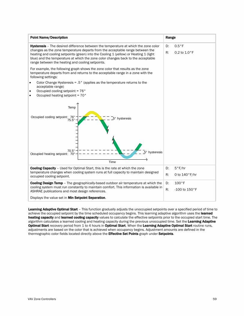
VAV Zone Controllers 59
Point Name/Description Range
Hysteresis
For example, the following graph shows the zone color that results as the zone temperature departs from and returns to the acceptable range in a zone with the following settings:
– The desired difference between the temperature at which the zone color changes as the zone temperature departs from the acceptable range between the heating and cooling setpoints (green) into the Cooling 1 (yellow) or Heating 1 (light blue) and the temperature at which the zone color changes back to the acceptable range between the heating and cooling setpoints.
• Color Change Hysteresis = .5° (applies as the temperature returns to the acceptable range)
• Occupied cooling setpoint = 76° • Occupied heating setpoint = 70°
Time
Temp
Occupied heating setpoint: 70°
75.5°
70.5°
Occupied cooling setpoint: 76° .5° hysteresis
.5° hysteresis
D:
R:
0.5°F
0.2 to 1.0°F
Cooling Capacity D: – Used for Optimal Start, this is the rate at which the zone temperature changes when cooling system runs at full capacity to maintain designed occupied cooling setpoint. R:
5°F/hr
0 to 140°F/hr
Cooling Design Temp
Displays the value set in
– The geographically-based outdoor air temperature at which the cooling system must run constantly to maintain comfort. This information is available in ASHRAE publications and most design references.
Min Setpoint Separation
D:
.
R:
100°F
-100 to 150°F
Learning Adaptive Optimal Start – This function gradually adjusts the unoccupied setpoints over a specified period of time to achieve the occupied setpoint by the time scheduled occupancy begins. This learning adaptive algorithm uses the learned heating capacity and learned cooling capacity values to calculate the effective setpoints prior to the occupied start time. The algorithm calculates a learned cooling and heating capacity during the previous unoccupied time. Set the Learning Adaptive Optimal Start recovery period from 1 to 4 hours in Optimal Start. When the Learning Adaptive Optimal Start routine runs, adjustments are based on the color that is achieved when occupancy begins. Adjustment amounts are defined in the thermographic color fields located directly above the Effective Set Points graph under Setpoints.
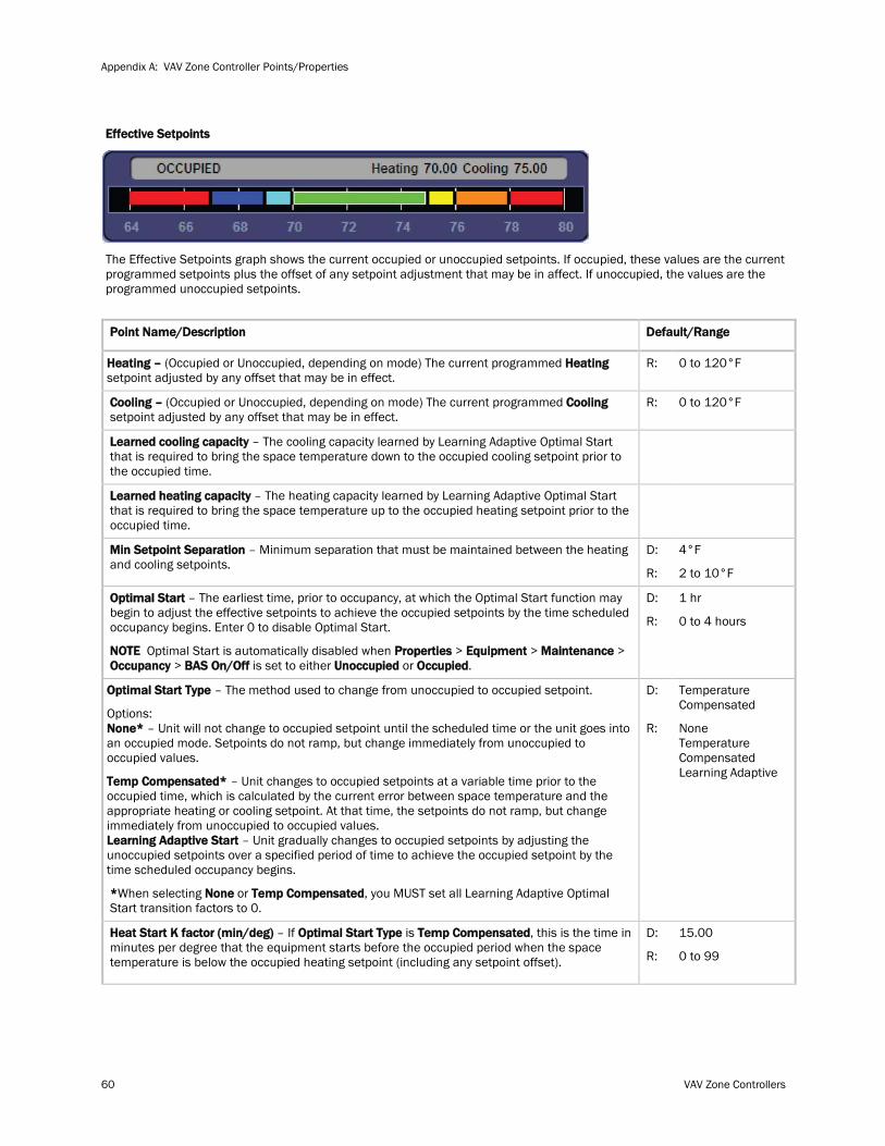
Appendix A: VAV Zone Controller Points/Properties
60 VAV Zone Controllers
Effective Setpoints
The Effective Setpoints graph shows the current occupied or unoccupied setpoints. If occupied, these values are the current programmed setpoints plus the offset of any setpoint adjustment that may be in affect. If unoccupied, the values are the programmed unoccupied setpoints.
Point Name/Description
Heating – (Occupied or Unoccupied, depending on mode) The current programmed Heating setpoint adjusted by any offset that may be in effect.
Default/Range
R: 0 to 120°F
Cooling – (Occupied or Unoccupied, depending on mode) The current programmed Cooling R: setpoint adjusted by any offset that may be in effect.
0 to 120°F
Learned cooling capacity – The cooling capacity learned by Learning Adaptive Optimal Start that is required to bring the space temperature down to the occupied cooling setpoint prior to the occupied time.
Learned heating capacity – The heating capacity learned by Learning Adaptive Optimal Start that is required to bring the space temperature up to the occupied heating setpoint prior to the occupied time.
Min Setpoint Separation D: – Minimum separation that must be maintained between the heating and cooling setpoints.
R:
4°F
2 to 10°F
Optimal Start – The earliest time, prior to occupancy, at which the Optimal Start function may begin to adjust the effective setpoints to achieve the occupied setpoints by the time scheduled occupancy begins. Enter 0 to disable Optimal Start.
NOTE Optimal Start is automatically disabled when Properties > Equipment > Maintenance > Occupancy > BAS On/Off is set to either Unoccupied or Occupied
D:
.
R:
1 hr
0 to 4 hours
Optimal Start Type – The method used to change from unoccupied to occupied setpoint.
Options: None* – Unit will not change to occupied setpoint until the scheduled time or the unit goes into an occupied mode. Setpoints do not ramp, but change immediately from unoccupied to occupied values.
Temp Compensated* – Unit changes to occupied setpoints at a variable time prior to the occupied time, which is calculated by the current error between space temperature and the appropriate heating or cooling setpoint. At that time, the setpoints do not ramp, but change immediately from unoccupied to occupied values. Learning Adaptive Start – Unit gradually changes to occupied setpoints by adjusting the unoccupied setpoints over a specified period of time to achieve the occupied setpoint by the time scheduled occupancy begins.
*When selecting None or Temp Compensated
D:
, you MUST set all Learning Adaptive Optimal Start transition factors to 0.
R:
Temperature Compensated
None Temperature Compensated Learning Adaptive
Heat Start K factor (min/deg) – If Optimal Start Type is Temp Compensated D: , this is the time in minutes per degree that the equipment starts before the occupied period when the space temperature is below the occupied heating setpoint (including any setpoint offset). R:
15.00
0 to 99
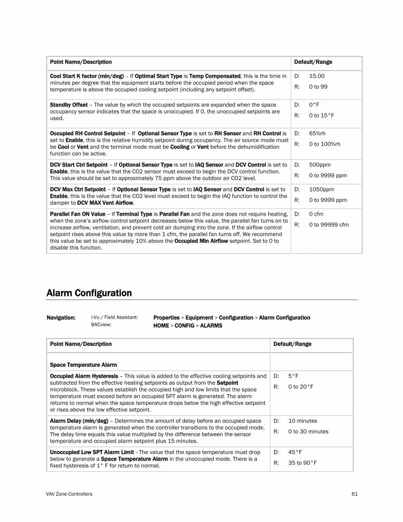
VAV Zone Controllers 61
Point Name/Description Default/Range
Cool Start K factor (min/deg) – If Optimal Start Type is Temp Compensated D: , this is the time in minutes per degree that the equipment starts before the occupied period when the space temperature is above the occupied cooling setpoint (including any setpoint offset). R:
15.00
0 to 99
Standby Offset D: – The value by which the occupied setpoints are expanded when the space occupancy sensor indicates that the space is unoccupied. If 0, the unoccupied setpoints are used. R:
0°F
0 to 15°F
Occupied RH Control Setpoint – If Optional Sensor Type is set to RH Sensor and RH Control is set to Enable, this is the relative humidity setpoint during occupancy. The air source mode must be Cool or Vent and the terminal mode must be Cooling or Vent
D:
before the dehumidification function can be active.
R:
65%rh
0 to 100%rh
DCV Start Ctrl Setpoint – If Optional Sensor Type is set to IAQ Sensor and DCV Control is set to Enable
D: , this is the value that the CO2 sensor must exceed to begin the DCV control function.
This value should be set to approximately 75 ppm above the outdoor air CO2 level. R:
500ppm
0 to 9999 ppm
DCV Max Ctrl Setpoint – If Optional Sensor Type is set to IAQ Sensor and DCV Control is set to Enable, this is the value that the CO2 level must exceed to begin the IAQ function to control the damper to DCV MAX Vent Airflow
D:
. R:
1050ppm
0 to 9999 ppm
Parallel Fan ON Value – If Terminal Type is Parallel Fan and the zone does not require heating, when the zone’s airflow control setpoint decreases below this value, the parallel fan turns on to increase airflow, ventilation, and prevent cold air dumping into the zone. If the airflow control setpoint rises above this value by more than 1 cfm, the parallel fan turns off. We recommend this value be set to approximately 10% above the Occupied Min Airflow
D:
setpoint. Set to 0 to disable this function.
R:
0 cfm
0 to 99999 cfm
Alarm Configuration
i-Vu / Field Assistant: Navigation: BACview:
Properties > Equipment > Configuration > Alarm Configuration HOME > CONFIG >
ALARMS
Point Name/Description Default/Range
Space Temperature Alarm
Occupied Alarm Hysteresis – This value is added to the effective cooling setpoints and subtracted from the effective heating setpoints as output from the Setpoint
D:
microblock. These values establish the occupied high and low limits that the space temperature must exceed before an occupied SPT alarm is generated. The alarm returns to normal when the space temperature drops below the high effective setpoint or rises above the low effective setpoint.
R:
5°F
0 to 20°F
Alarm Delay (min/deg) D: – Determines the amount of delay before an occupied space temperature alarm is generated when the controller transitions to the occupied mode. The delay time equals this value multiplied by the difference between the sensor temperature and occupied alarm setpoint plus 15 minutes.
R:
10 minutes
0 to 30 minutes
Unoccupied Low SPT Alarm Limit –The value that the space temperature must drop below to generate a Space Temperature Alarm
D: in the unoccupied mode. There is a
fixed hysteresis of 1° F for return to normal. R:
45°F
35 to 90°F
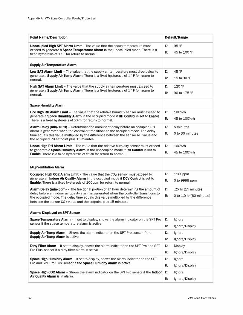
Appendix A: VAV Zone Controller Points/Properties
62 VAV Zone Controllers
Point Name/Description Default/Range
Unoccupied High SPT Alarm Limit – The value that the space temperature must exceed to generate a Space Temperature Alarm
D: in the unoccupied mode. There is a
fixed hysteresis of 1° F for return to normal. R:
95°F
45 to 100°F
Supply Air Temperature Alarm
Low SAT Alarm Limit – The value that the supply air temperature must drop below to generate a Supply Air Temp Alarm
D: . There is a fixed hysteresis of 1° F for return to
normal. R:
45°F
15 to 90°F
High SAT Alarm Limit – The value that the supply air temperature must exceed to generate a Supply Air Temp Alarm
D: . There is a fixed hysteresis of 1° F for return to
normal. R:
120°F
90 to 175°F
Space Humidity Alarm
Occ High RH Alarm Limit – The value that the relative humidity sensor must exceed to generate a Space Humidity Alarm in the occupied mode if RH Control is set to Enable
D: .
There is a fixed hysteresis of 5%rh for return to normal. R:
100%rh
45 to 100%rh
Alarm Delay (min/%RH) D: – Determines the amount of delay before an occupied RH alarm is generated when the controller transitions to the occupied mode. The delay time equals this value multiplied by the difference between the sensor RH value and the occupied RH setpoint plus 15 minutes.
R:
5 minutes
0 to 30 minutes
Unocc High RH Alarm Limit – The value that the relative humidity sensor must exceed to generate a Space Humidity Alarm in the unoccupied mode if RH Control is set to Enable
D:
. There is a fixed hysteresis of 5%rh for return to normal. R:
100%rh
45 to 100%rh
IAQ/Ventilation Alarm
Occupied High CO2 Alarm Limit – The value that the CO2 D: sensor must exceed to generate an Indoor Air Quality Alarm in the occupied mode if DCV Control is set to Enable. There is a fixed hysteresis of 100ppm for return to normal. R:
1100ppm
0 to 9999 ppm
Alarm Delay (min/ppm) – The fractional portion of an hour determining the amount of delay before an indoor air quality alarm is generated when the controller transitions to the occupied mode. The delay time equals this value multiplied by the difference between the sensor CO2
D:
value and the setpoint plus 15 minutes.
R:
.25 hr (15 minutes)
0 to 1.0 hr (60 minutes)
Alarms Displayed on SPT Sensor
Space Temperature Alarm – If set to display, shows the alarm indicator on the SPT Pro sensor if the space temperature alarm is active.
D:
R:
Ignore
Ignore/Display
Supply Air Temp Alarm – Shows the alarm indicator on the SPT Pro sensor if the Supply Air Temp Alarm is active.
D:
R:
Ignore
Ignore/Display
Dirty Filter Alarm – If set to display, shows the alarm indicator on the SPT Pro and SPT Pro Plus' sensor if a dirty filter alarm is active.
D:
R:
Display
Ignore/Display
Space High Humidity Alarm – If set to display, shows the alarm indicator on the SPT Pro and SPT Pro Plus' sensor if the Space Humidity Alarm is active.
D:
R:
Ignore
Ignore/Display
Space High CO2 Alarm – Shows the alarm indicator on the SPT Pro sensor if the Indoor Air Quality Alarm is in alarm.
D:
R:
Ignore
Ignore/Display
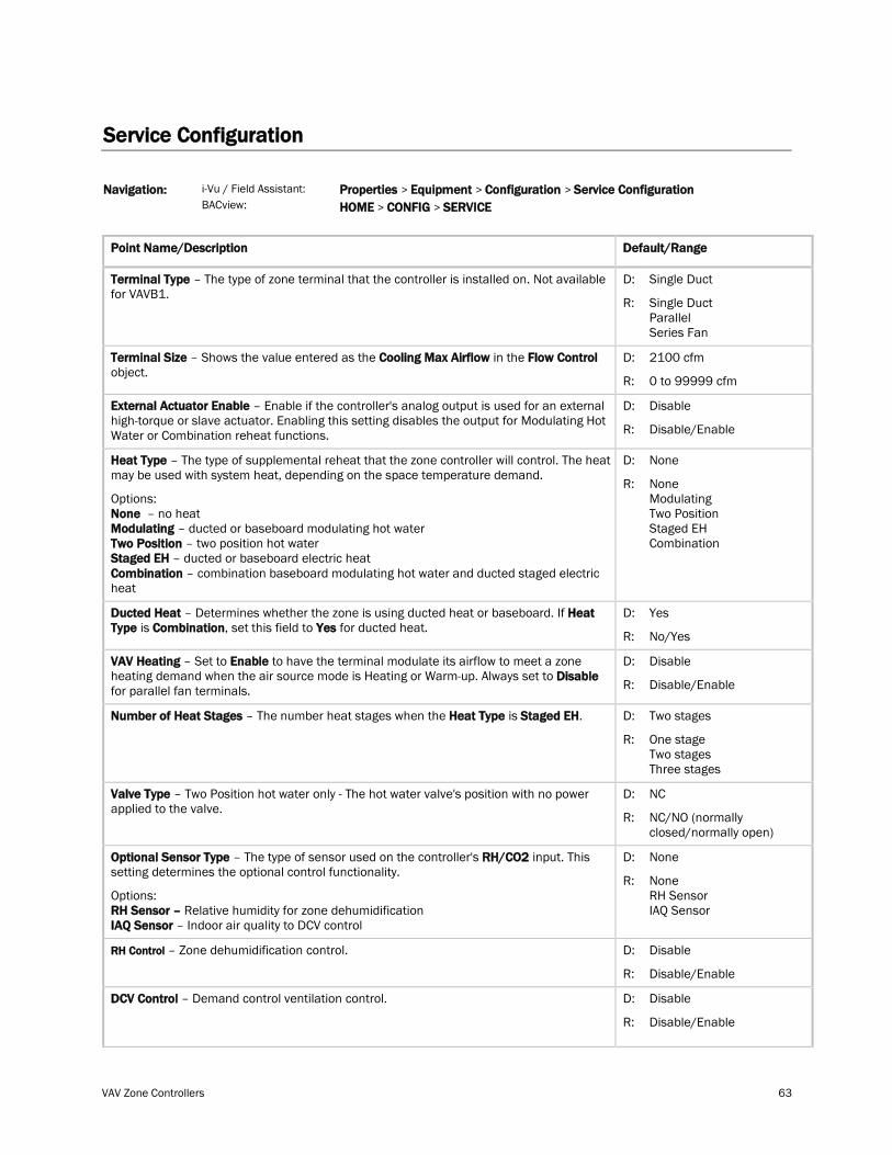
VAV Zone Controllers 63
Service Configuration
Navigation: i-Vu / Field Assistant:
BACview: Properties > Equipment > Configuration > Service Configuration HOME > CONFIG > SERVICE
Point Name/Description Default/Range
Terminal Type – The type of zone terminal that the controller is installed on. Not available for VAVB1.
D:
R:
Single Duct
Single Duct Parallel Series Fan
Terminal Size – Shows the value entered as the Cooling Max Airflow in the Flow Control object.
D:
R:
2100 cfm
0 to 99999 cfm
External Actuator Enable – Enable if the controller's analog output is used for an external high-torque or slave actuator. Enabling this setting disables the output for Modulating Hot Water or Combination reheat functions.
D:
R:
Disable
Disable/Enable
Heat Type – The type of supplemental reheat that the zone controller will control. The heat may be used with system heat, depending on the space temperature demand.
Options: None – no heat Modulating – ducted or baseboard modulating hot water Two Position – two position hot water Staged EH – ducted or baseboard electric heat Combination – combination baseboard modulating hot water and ducted staged electric heat
D:
R:
None
None Modulating Two Position Staged EH Combination
Ducted Heat – Determines whether the zone is using ducted heat or baseboard. If Heat Type is Combination, set this field to Yes for ducted heat.
D:
R:
Yes
No/Yes
VAV Heating – Set to Enable to have the terminal modulate its airflow to meet a zone heating demand when the air source mode is Heating or Warm-up. Always set to Disable for parallel fan terminals.
D:
R:
Disable
Disable/Enable
Number of Heat Stages – The number heat stages when the Heat Type is Staged EH. D:
R:
Two stages
One stage Two stages Three stages
Valve Type – Two Position hot water only - The hot water valve's position with no power applied to the valve.
D:
R:
NC
NC/NO (normally closed/normally open)
Optional Sensor Type – The type of sensor used on the controller's RH/CO2 input. This setting determines the optional control functionality.
Options: RH Sensor – Relative humidity for zone dehumidification IAQ Sensor – Indoor air quality to DCV control
D:
R:
None
None RH Sensor IAQ Sensor
RH Control D: – Zone dehumidification control.
R:
Disable
Disable/Enable
DCV Control – Demand control ventilation control.
D:
R:
Disable
Disable/Enable
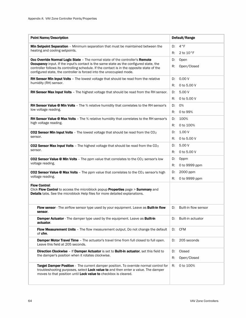
Appendix A: VAV Zone Controller Points/Properties
64 VAV Zone Controllers
Point Name/Description Default/Range
Min Setpoint Separation – Minimum separation that must be maintained between the heating and cooling setpoints.
D:
R:
4°F
2 to 10°F
Occ Override Normal Logic State – The normal state of the controller's Remote Occupancy input. If the input's contact is the same state as the configured state, the controller follows its controlling schedule. If the contact is in the opposite state of the configured state, the controller is forced into the unoccupied mode.
D:
R:
Open
Open/Closed
RH Sensor Min Input Volts – The lowest voltage that should be read from the relative humidity (RH) sensor.
D:
R:
0.00 V
0 to 5.00 V
RH Sensor Max Input Volts – The highest voltage that should be read from the RH sensor. D:
R:
5.00 V
0 to 5.00 V
RH Sensor Value @ Min Volts – The % relative humidity that correlates to the RH sensor's low voltage reading.
D:
R:
0%
0 to 99%
RH Sensor Value @ Max Volts – The % relative humidity that correlates to the RH sensor's high voltage reading.
D:
R:
100%
0 to 100%
CO2 Sensor Min Input Volts – The lowest voltage that should be read from the CO2 D: sensor. R:
1.00 V
0 to 5.00 V
CO2 Sensor Max Input Volts – The highest voltage that should be read from the CO2 D: sensor. R:
5.00 V
0 to 5.00 V
CO2 Sensor Value @ Min Volts – The ppm value that correlates to the CO2 D: sensor's low voltage reading. R:
0ppm
0 to 9999 ppm
CO2 Sensor Value @ Max Volts – The ppm value that correlates to the CO2 D: sensor's high voltage reading. R:
2000 ppm
0 to 9999 ppm
Flow Control: Click Flow Control to access the microblock popup Properties page > Summary and Details tabs. See the microblock Help files for more detailed explanations.
Flow sensor - The airflow sensor type used by your equipment. Leave as Built-in flow sensor.
D: Built-in flow sensor
Damper Actuator - The damper type used by the equipment. Leave as Built-in actuator.
D: Built-in actuator
Flow Measurement Units – The flow measurement output. Do not change the default of cfm.
D: CFM
Damper Motor Travel Time – The actuator's travel time from full closed to full open. Leave this field at 205 seconds.
D: 205 seconds
Direction Clockwise – If Damper Actuator is set to Built-in actuator, set this field to the damper's position when it rotates clockwise.
D:
R:
Closed
Open/Closed
Target Damper Position - The current damper position. To override normal control for troubleshooting purposes, select Lock value to and then enter a value. The damper moves to that position until Lock value to checkbox is cleared.
R: 0 to 100%
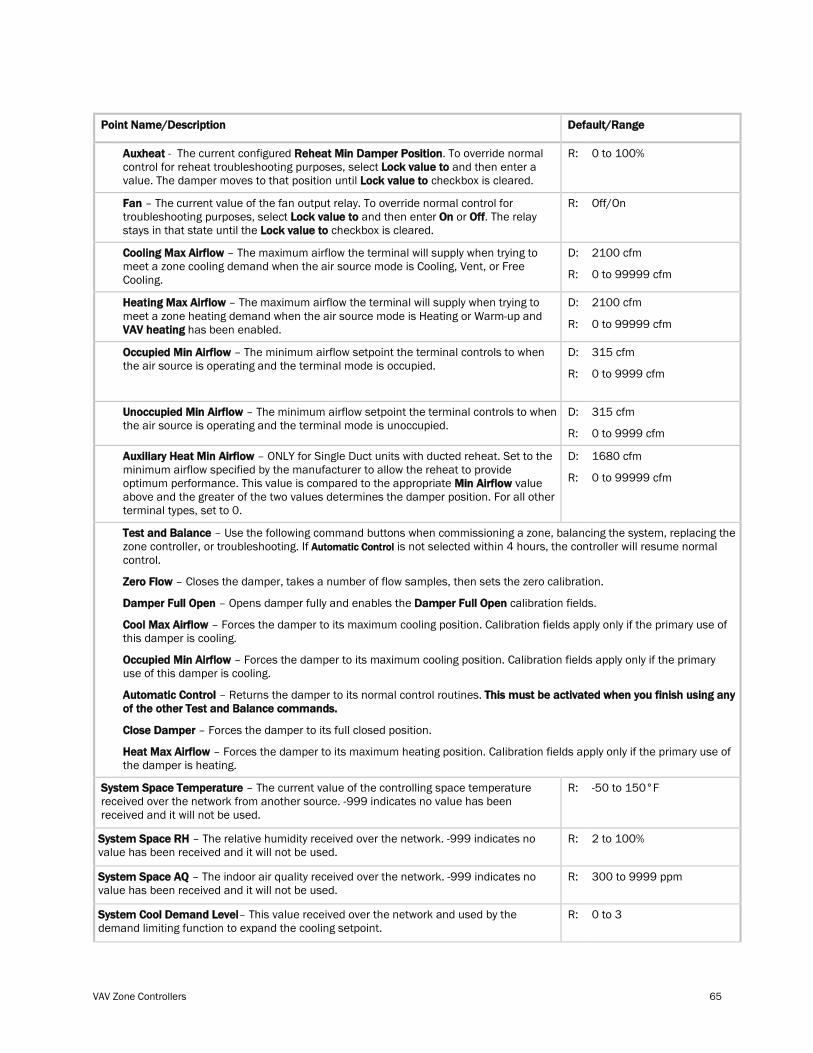
VAV Zone Controllers 65
Point Name/Description Default/Range
Auxheat - The current configured Reheat Min Damper Position. To override normal control for reheat troubleshooting purposes, select Lock value to and then enter a value. The damper moves to that position until Lock value to checkbox is cleared.
R: 0 to 100%
Fan – The current value of the fan output relay. To override normal control for troubleshooting purposes, select Lock value to and then enter On or Off. The relay stays in that state until the Lock value to checkbox is cleared.
R: Off/On
Cooling Max Airflow – The maximum airflow the terminal will supply when trying to meet a zone cooling demand when the air source mode is Cooling, Vent, or Free Cooling.
D:
R:
2100 cfm
0 to 99999 cfm
Heating Max Airflow – The maximum airflow the terminal will supply when trying to meet a zone heating demand when the air source mode is Heating or Warm-up and VAV heating has been enabled.
D:
R:
2100 cfm
0 to 99999 cfm
Occupied Min Airflow – The minimum airflow setpoint the terminal controls to when the air source is operating and the terminal mode is occupied.
D:
R:
315 cfm
0 to 9999 cfm
Unoccupied Min Airflow – The minimum airflow setpoint the terminal controls to when the air source is operating and the terminal mode is unoccupied.
D:
R:
315 cfm
0 to 9999 cfm
Auxiliary Heat Min Airflow – ONLY for Single Duct units with ducted reheat. Set to the minimum airflow specified by the manufacturer to allow the reheat to provide optimum performance. This value is compared to the appropriate Min Airflow value above and the greater of the two values determines the damper position. For all other terminal types, set to 0.
D:
R:
1680 cfm
0 to 99999 cfm
Test and Balance – Use the following command buttons when commissioning a zone, balancing the system, replacing the zone controller, or troubleshooting. If Automatic Control
Zero Flow – Closes the damper, takes a number of flow samples, then sets the zero calibration.
is not selected within 4 hours, the controller will resume normal control.
Damper Full Open – Opens damper fully and enables the Damper Full Open calibration fields.
Cool Max Airflow – Forces the damper to its maximum cooling position. Calibration fields apply only if the primary use of this damper is cooling.
Occupied Min Airflow – Forces the damper to its maximum cooling position. Calibration fields apply only if the primary use of this damper is cooling.
Automatic Control – Returns the damper to its normal control routines. This must be activated when you finish using any of the other Test and Balance commands.
Close Damper – Forces the damper to its full closed position.
Heat Max Airflow – Forces the damper to its maximum heating position. Calibration fields apply only if the primary use of the damper is heating.
System Space Temperature – The current value of the controlling space temperature received over the network from another source. -999 indicates no value has been received and it will not be used.
R: -50 to 150°F
System Space RH – The relative humidity received over the network. -999 indicates no value has been received and it will not be used.
R: 2 to 100%
System Space AQ – The indoor air quality received over the network. -999 indicates no value has been received and it will not be used.
R: 300 to 9999 ppm
System Cool Demand Level– This value received over the network and used by the demand limiting function to expand the cooling setpoint.
R: 0 to 3
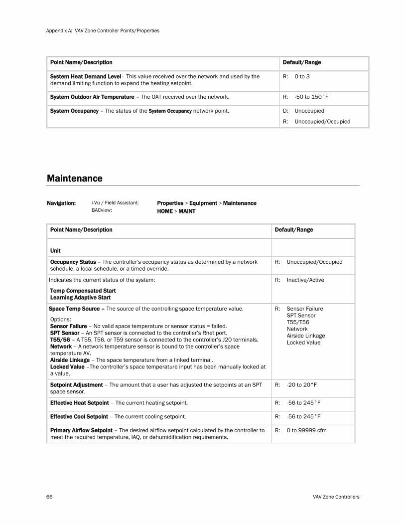
Appendix A: VAV Zone Controller Points/Properties
66 VAV Zone Controllers
Point Name/Description Default/Range
System Heat Demand Level– This value received over the network and used by the demand limiting function to expand the heating setpoint.
R: 0 to 3
System Outdoor Air Temperature – The OAT received over the network. R: -50 to 150°F
System Occupancy – The status of the System Occupancy D: network point.
R:
Unoccupied
Unoccupied/Occupied
Maintenance
Navigation: i-Vu / Field Assistant:
BACview: Properties > Equipment > Maintenance HOME > MAINT
Point Name/Description Default/Range
Unit
Occupancy Status – The controller's occupancy status as determined by a network schedule, a local schedule, or a timed override.
R: Unoccupied/Occupied
Indicates the current status of the system:
Temp Compensated Start Learning Adaptive Start
R: Inactive/Active
Space Temp Source – The source of the controlling space temperature value.
Options: Sensor Failure – No valid space temperature or sensor status = failed. SPT Sensor – An SPT sensor is connected to the controller’s Rnet port. T55/56 – A T55, T56, or T59 sensor is connected to the controller’s J20 terminals. Network – A network temperature sensor is bound to the controller’s space temperature AV. Airside Linkage – The space temperature from a linked terminal. Locked Value –The controller’s space temperature input has been manually locked at a value.
R: Sensor Failure SPT Sensor T55/T56 Network Airside Linkage Locked Value
Setpoint Adjustment – The amount that a user has adjusted the setpoints at an SPT space sensor.
R: -20 to 20°F
Effective Heat Setpoint – The current heating setpoint. R: -56 to 245°F
Effective Cool Setpoint – The current cooling setpoint. R: -56 to 245°F
Primary Airflow Setpoint – The desired airflow setpoint calculated by the controller to meet the required temperature, IAQ, or dehumidification requirements.
R: 0 to 99999 cfm
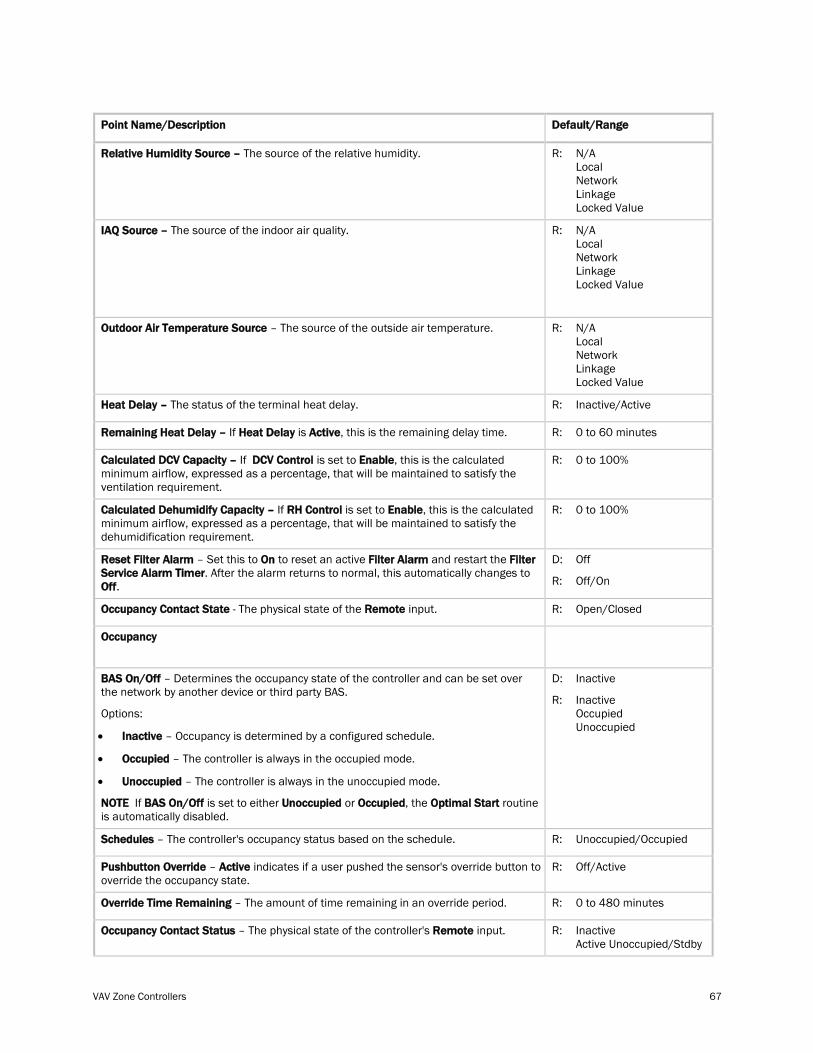
VAV Zone Controllers 67
Point Name/Description Default/Range
Relative Humidity Source – The source of the relative humidity. R: N/A Local Network Linkage Locked Value
IAQ Source – The source of the indoor air quality. R: N/A Local Network Linkage Locked Value
Outdoor Air Temperature Source – The source of the outside air temperature. R: N/A Local Network Linkage Locked Value
Heat Delay – The status of the terminal heat delay. R: Inactive/Active
Remaining Heat Delay – If Heat Delay is Active, this is the remaining delay time. R: 0 to 60 minutes
Calculated DCV Capacity – If DCV Control is set to Enable, this is the calculated minimum airflow, expressed as a percentage, that will be maintained to satisfy the ventilation requirement.
R: 0 to 100%
Calculated Dehumidify Capacity – If RH Control is set to Enable, this is the calculated minimum airflow, expressed as a percentage, that will be maintained to satisfy the dehumidification requirement.
R: 0 to 100%
Reset Filter Alarm – Set this to On to reset an active Filter Alarm and restart the Filter Service Alarm Timer. After the alarm returns to normal, this automatically changes to Off.
D:
R:
Off
Off/On
Occupancy Contact State - The physical state of the Remote input. R: Open/Closed
Occupancy
BAS On/Off – Determines the occupancy state of the controller and can be set over the network by another device or third party BAS.
Options:
• Inactive – Occupancy is determined by a configured schedule.
• Occupied – The controller is always in the occupied mode.
• Unoccupied – The controller is always in the unoccupied mode.
NOTE If BAS On/Off is set to either Unoccupied or Occupied, the Optimal Start routine is automatically disabled.
D:
R:
Inactive
Inactive Occupied Unoccupied
Schedules – The controller's occupancy status based on the schedule. R: Unoccupied/Occupied
Pushbutton Override – Active indicates if a user pushed the sensor's override button to override the occupancy state.
R: Off/Active
Override Time Remaining – The amount of time remaining in an override period. R: 0 to 480 minutes
Occupancy Contact Status – The physical state of the controller's Remote input. R: Inactive Active Unoccupied/Stdby
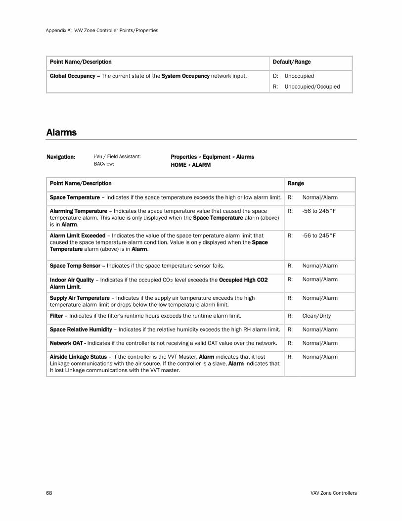
Appendix A: VAV Zone Controller Points/Properties
68 VAV Zone Controllers
Point Name/Description Default/Range
Global Occupancy – The current state of the System Occupancy network input. D:
R:
Unoccupied
Unoccupied/Occupied
Alarms
Navigation: i-Vu / Field Assistant:
BACview: Properties > Equipment > Alarms HOME > ALARM
Point Name/Description Range
Space Temperature – Indicates if the space temperature exceeds the high or low alarm limit. R: Normal/Alarm
Alarming Temperature – Indicates the space temperature value that caused the space temperature alarm. This value is only displayed when the Space Temperature alarm (above) is in Alarm.
R: -56 to 245°F
Alarm Limit Exceeded – Indicates the value of the space temperature alarm limit that caused the space temperature alarm condition. Value is only displayed when the Space Temperature alarm (above) is in Alarm.
R: -56 to 245°F
Space Temp Sensor – Indicates if the space temperature sensor fails. R: Normal/Alarm
Indoor Air Quality – Indicates if the occupied CO2 R: level exceeds the Occupied High CO2 Alarm Limit.
Normal/Alarm
Supply Air Temperature – Indicates if the supply air temperature exceeds the high temperature alarm limit or drops below the low temperature alarm limit.
R: Normal/Alarm
Filter – Indicates if the filter's runtime hours exceeds the runtime alarm limit. R: Clean/Dirty
Space Relative Humidity – Indicates if the relative humidity exceeds the high RH alarm limit. R: Normal/Alarm
Network OAT - Indicates if the controller is not receiving a valid OAT value over the network. R: Normal/Alarm
Airside Linkage Status – If the controller is the VVT Master, Alarm indicates that it lost Linkage communications with the air source. If the controller is a slave, Alarm indicates that it lost Linkage communications with the VVT master.
R: Normal/Alarm
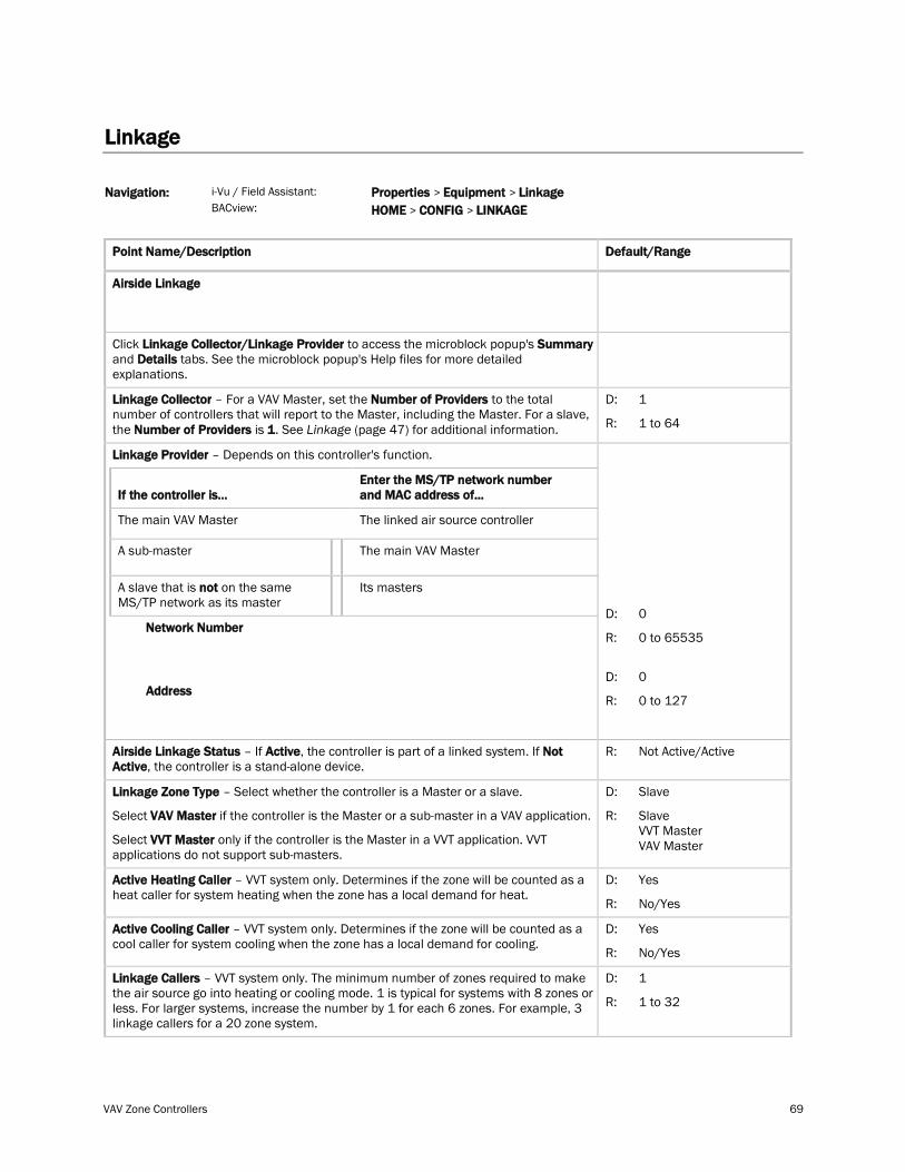
VAV Zone Controllers 69
Linkage
Navigation: i-Vu / Field Assistant:
BACview: Properties > Equipment > Linkage HOME > CONFIG > LINKAGE
Point Name/Description Default/Range
Airside Linkage
Click Linkage Collector/Linkage Provider to access the microblock popup's Summary and Details tabs. See the microblock popup's Help files for more detailed explanations.
Linkage Collector – For a VAV Master, set the Number of Providers to the total number of controllers that will report to the Master, including the Master. For a slave, the Number of Providers is 1. See Linkage 47 (page ) for additional information.
D:
R:
1
1 to 64
Linkage Provider – Depends on this controller's function.
If the controller is...
Enter the MS/TP network number and MAC address of...
The main VAV Master The linked air source controller
A sub-master The main VAV Master
A slave that is not on the same MS/TP network as its master Its masters
Network Number
Address
D:
R:
D:
R:
0
0 to 65535
0
0 to 127
Airside Linkage Status – If Active, the controller is part of a linked system. If Not Active, the controller is a stand-alone device.
R: Not Active/Active
Linkage Zone Type – Select whether the controller is a Master or a slave.
Select VAV Master if the controller is the Master or a sub-master in a VAV application.
Select VVT Master only if the controller is the Master in a VVT application. VVT applications do not support sub-masters.
D:
R:
Slave
Slave VVT Master VAV Master
Active Heating Caller – VVT system only. Determines if the zone will be counted as a heat caller for system heating when the zone has a local demand for heat.
D:
R:
Yes
No/Yes
Active Cooling Caller – VVT system only. Determines if the zone will be counted as a cool caller for system cooling when the zone has a local demand for cooling.
D:
R:
Yes
No/Yes
Linkage Callers – VVT system only. The minimum number of zones required to make the air source go into heating or cooling mode. 1 is typical for systems with 8 zones or less. For larger systems, increase the number by 1 for each 6 zones. For example, 3 linkage callers for a 20 zone system.
D:
R:
1
1 to 32
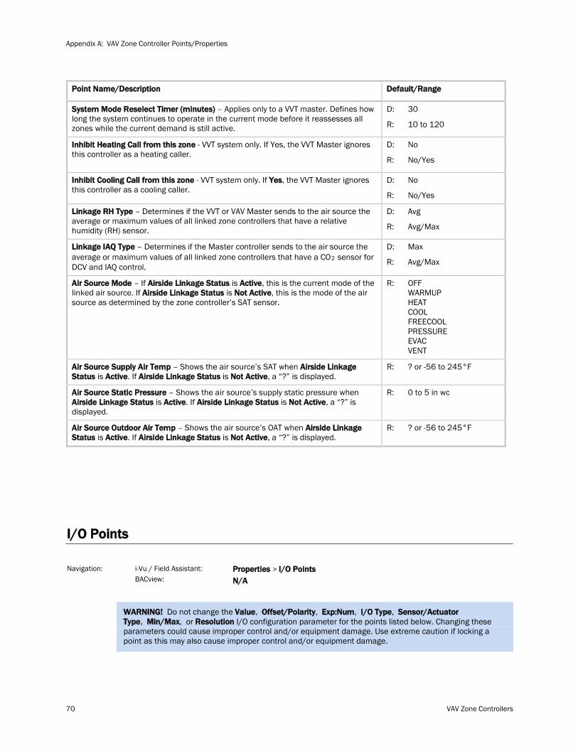
Appendix A: VAV Zone Controller Points/Properties
70 VAV Zone Controllers
Point Name/Description Default/Range
System Mode Reselect Timer (minutes) – Applies only to a VVT master. Defines how long the system continues to operate in the current mode before it reassesses all zones while the current demand is still active.
D:
R:
30
10 to 120
Inhibit Heating Call from this zone - VVT system only. If Yes, the VVT Master ignores this controller as a heating caller.
D:
R:
No
No/Yes
Inhibit Cooling Call from this zone - VVT system only. If Yes, the VVT Master ignores this controller as a cooling caller.
D:
R:
No
No/Yes
Linkage RH Type – Determines if the VVT or VAV Master sends to the air source the average or maximum values of all linked zone controllers that have a relative humidity (RH) sensor.
D:
R:
Avg
Avg/Max
Linkage IAQ Type – Determines if the Master controller sends to the air source the average or maximum values of all linked zone controllers that have a CO2
D: sensor for
DCV and IAQ control. R:
Max
Avg/Max
Air Source Mode – If Airside Linkage Status is Active, this is the current mode of the linked air source. If Airside Linkage Status is Not Active, this is the mode of the air source as determined by the zone controller’s SAT sensor.
R: OFF WARMUP HEAT COOL FREECOOL PRESSURE EVAC VENT
Air Source Supply Air Temp – Shows the air source’s SAT when Airside Linkage Status is Active. If Airside Linkage Status is Not Active, a “?” is displayed.
R: ? or -56 to 245°F
Air Source Static Pressure – Shows the air source’s supply static pressure when Airside Linkage Status is Active. If Airside Linkage Status is Not Active, a “?” is displayed.
R: 0 to 5 in wc
Air Source Outdoor Air Temp – Shows the air source’s OAT when Airside Linkage Status is Active. If Airside Linkage Status is Not Active, a “?” is displayed.
R: ? or -56 to 245°F
I/O Points
Navigation: i-Vu / Field Assistant:
BACview: Properties > I/O Points N/A
WARNING! Do not change the Value, Offset/Polarity, Exp:Num, I/O Type, Sensor/Actuator Type, Min/Max, or Resolution I/O configuration parameter for the points listed below. Changing these parameters could cause improper control and/or equipment damage. Use extreme caution if locking a point as this may also cause improper control and/or equipment damage.
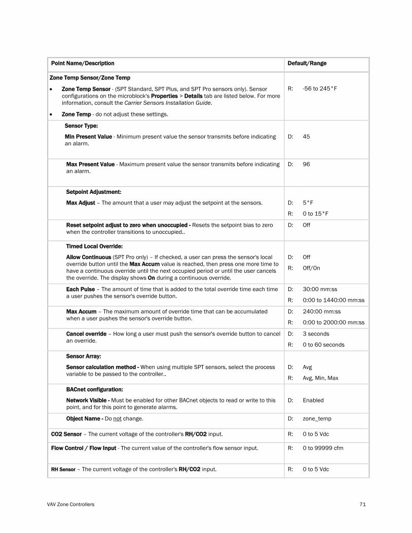
VAV Zone Controllers 71
Point Name/Description Default/Range
Zone Temp Sensor/Zone Temp
• Zone Temp Sensor - (SPT Standard, SPT Plus, and SPT Pro sensors only). Sensor configurations on the microblock's Properties > Details tab are listed below. For more information, consult the Carrier Sensors Installation Guide.
• Zone Temp - do not adjust these settings.
R:
-56 to 245°F
Sensor Type:
Min Present Value - Minimum present value the sensor transmits before indicating an alarm.
D:
45
Max Present Value - Maximum present value the sensor transmits before indicating an alarm.
D:
96
Setpoint Adjustment:
Max Adjust – The amount that a user may adjust the setpoint at the sensors.
D:
R:
5°F
0 to 15°F
Reset setpoint adjust to zero when unoccupied - Resets the setpoint bias to zero when the controller transitions to unoccupied..
D: Off
Timed Local Override:
Allow Continuous (SPT Pro only) – If checked, a user can press the sensor's local override button until the Max Accum value is reached, then press one more time to have a continuous override until the next occupied period or until the user cancels the override. The display shows On during a continuous override.
D:
R:
Off
Off/On
Each Pulse – The amount of time that is added to the total override time each time a user pushes the sensor's override button.
D:
R:
30:00 mm:ss
0:00 to 1440:00 mm:ss
Max Accum – The maximum amount of override time that can be accumulated when a user pushes the sensor's override button.
D:
R:
240:00 mm:ss
0:00 to 2000:00 mm:ss
Cancel override – How long a user must push the sensor's override button to cancel an override.
D:
R:
3 seconds
0 to 60 seconds
Sensor Array:
Sensor calculation method - When using multiple SPT sensors, select the process variable to be passed to the controller..
D:
R:
Avg
Avg, Min, Max
BACnet configuration:
Network Visible - Must be enabled for other BACnet objects to read or write to this point, and for this point to generate alarms.
D:
Enabled
Object Name - Do not D: change. zone_temp
CO2 Sensor – The current voltage of the controller's RH/CO2 input. R: 0 to 5 Vdc
Flow Control / Flow Input - The current value of the controller's flow sensor input. R: 0 to 99999 cfm
RH Sensor R: – The current voltage of the controller's RH/CO2 input. 0 to 5 Vdc
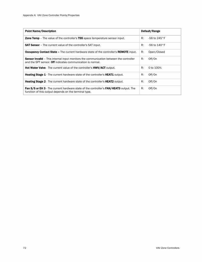
Appendix A: VAV Zone Controller Points/Properties
72 VAV Zone Controllers
Point Name/Description Default/Range
Zone Temp – The value of the controller's T55 space temperature sensor input. R: -56 to 245°F
SAT Sensor – The current value of the controller's SAT input. R: -56 to 140°F
Occupancy Contact State – The current hardware state of the controller's REMOTE input. R: Open/Closed
Sensor Invalid – This internal input monitors the communication between the controller and the SPT sensor. Off indicates communication is normal.
R: Off/On
Hot Water Valve - The current value of the controller's HWV/ACT output. R: 0 to 100%
Heating Stage 1 - The current hardware state of the controller's HEAT1 output. R: Off/On
Heating Stage 2 - The current hardware state of the controller's HEAT2 output. R: Off/On
Fan S/S or EH 3 - The current hardware state of the controller’s FAN/HEAT3 output. The function of this output depends on the terminal type.
R: Off/On
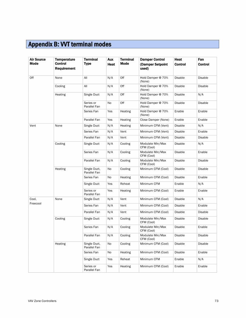
VAV Zone Controllers 73
Air Source Mode
Temperature Control Requirement
Terminal Type
Aux Heat
Terminal Mode
Damper Control (Damper Setpoint used)
Heat Control
Fan Control
Off
None All N/A Off Hold Damper @ 70%
(None) Disable Disable
Cooling All N/A Off Hold Damper @ 70% (None)
Disable Disable
Heating Single Duct N/A Off Hold Damper @ 70% (None)
Disable N/A
Series or Parallel Fan
No Off Hold Damper @ 70% (None)
Disable Disable
Series Fan Yes Heating Hold Damper @ 70% (None)
Enable Enable
Parallel Fan Yes Heating Close Damper (None) Enable Enable
Vent
None
Single Duct N/A Heating Minimum CFM (Vent) Disable N/A
Series Fan N/A Vent Minimum CFM (Vent) Disable Enable
Parallel Fan N/A Vent Minimum CFM (Vent) Disable Disable
Cooling
Single Duct N/A Cooling Modulate Min/Max
CFM (Cool) Disable N/A
Series Fan N/A Cooling Modulate Min/Max CFM (Cool)
Disable Enable
Parallel Fan N/A Cooling Modulate Min/Max CFM (Cool)
Disable Disable
Heating
Single Duct, Parallel Fan
No Cooling Minimum CFM (Cool) Disable Disable
Series Fan No Heating Minimum CFM (Cool) Disable Enable
Single Duct Yes Reheat Minimum CFM Enable N/A
Series or Parallel Fan
Yes Heating Minimum CFM (Cool) Enable Enable
Cool, Freecool
None Single Duct N/A Vent Minimum CFM (Cool) Disable N/A
Series Fan N/A Vent Minimum CFM (Cool) Disable Enable
Parallel Fan N/A Vent Minimum CFM (Cool) Disable Disable
Cooling Single Duct N/A Cooling Modulate Min/Max CFM (Cool)
Disable Disable
Series Fan N/A Cooling Modulate Min/Max CFM (Cool)
Disable Enable
Parallel Fan N/A Cooling Modulate Min/Max CFM (Cool)
Disable Disable
Heating Single Duct, Parallel Fan
No Cooling Minimum CFM (Cool) Disable Disable
Series Fan No Heating Minimum CFM (Cool) Disable Enable
Single Duct Yes Reheat Minimum CFM Enable N/A
Series or Parallel Fan
Yes Heating Minimum CFM (Cool) Enable Enable
Appendix B: VVT terminal modes
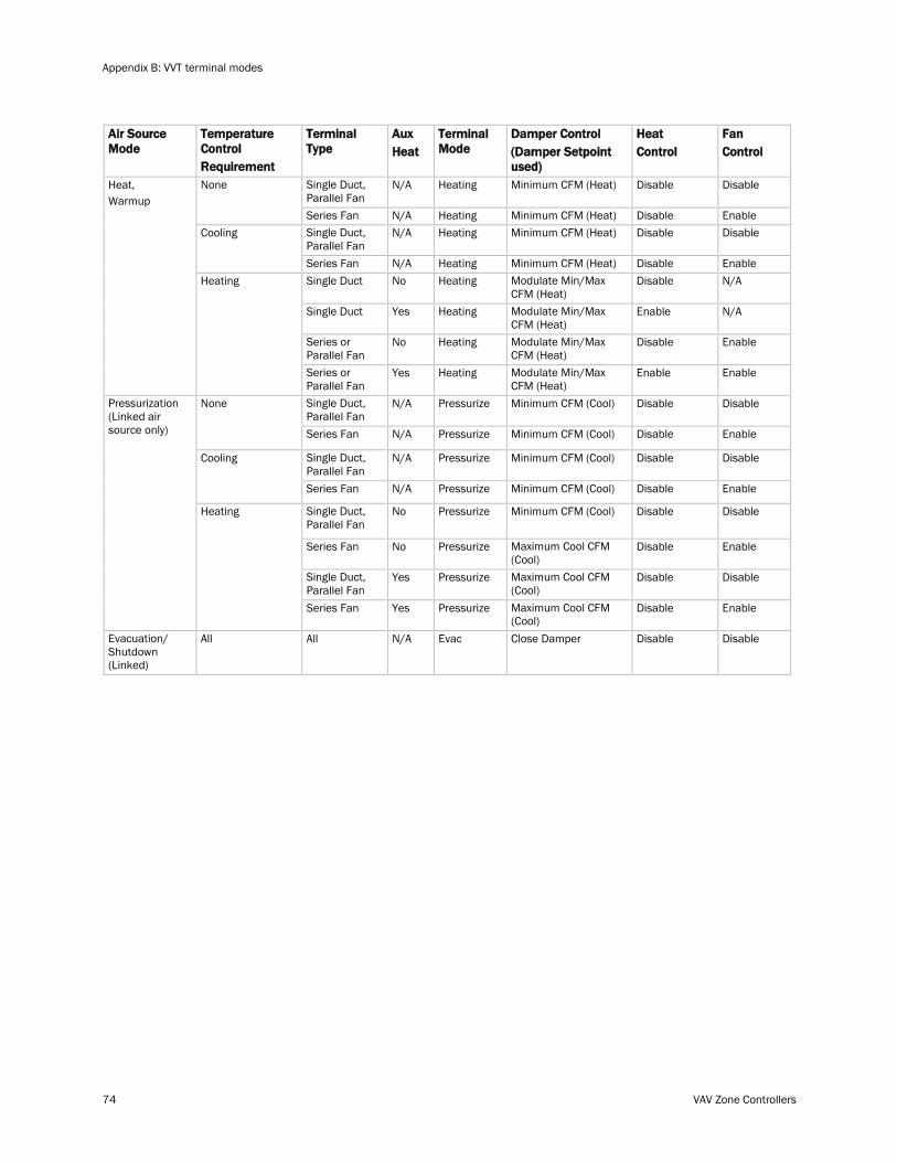
Appendix B: VVT terminal modes
74 VAV Zone Controllers
Air Source Mode
Temperature Control Requirement
Terminal Type
Aux Heat
Terminal Mode
Damper Control (Damper Setpoint used)
Heat Control
Fan Control
Heat, Warmup
None Single Duct, Parallel Fan
N/A Heating Minimum CFM (Heat) Disable Disable
Series Fan N/A Heating Minimum CFM (Heat) Disable Enable Cooling Single Duct,
Parallel Fan N/A Heating Minimum CFM (Heat) Disable Disable
Series Fan N/A Heating Minimum CFM (Heat) Disable Enable Heating Single Duct No Heating Modulate Min/Max
CFM (Heat) Disable N/A
Single Duct Yes Heating Modulate Min/Max CFM (Heat)
Enable N/A
Series or Parallel Fan
No Heating Modulate Min/Max CFM (Heat)
Disable Enable
Series or Parallel Fan
Yes Heating Modulate Min/Max CFM (Heat)
Enable Enable
Pressurization (Linked air source only)
None Single Duct, Parallel Fan
N/A Pressurize Minimum CFM (Cool) Disable Disable
Series Fan N/A Pressurize Minimum CFM (Cool) Disable Enable
Cooling Single Duct, Parallel Fan
N/A Pressurize Minimum CFM (Cool) Disable Disable
Series Fan N/A Pressurize Minimum CFM (Cool) Disable Enable
Heating Single Duct, Parallel Fan
No Pressurize Minimum CFM (Cool) Disable Disable
Series Fan No Pressurize Maximum Cool CFM (Cool)
Disable Enable
Single Duct, Parallel Fan
Yes Pressurize Maximum Cool CFM (Cool)
Disable Disable
Series Fan Yes Pressurize Maximum Cool CFM (Cool)
Disable Enable
Evacuation/ Shutdown (Linked)
All All N/A Evac Close Damper Disable Disable
Index
VAV Zone Controllers 75
A Actuator • 1, 5, 42 Addressing the controller • 12 Air source • 42, 47 Air source modes • 42, 46, 50 Airside linkage • 69 Alarm configuration • 61 Alarms • 46, 68
B BACnet compliance • 5, 53 BACnet port • 5, 13 BACview • 33 Balancing the system • 23 Battery • 5, 52 BT485 • 5, 12 bypass controller • 47
C CO2 sensor • 44 Compliance • 53 Control programs • 5
D Damper • 9 Dehumidification • 44 Demand control ventilation (DCV) • 44 Demand level • 47 Demand limiting • 47 Dimensions • 5 Duct sensors
Supply Air Temperature sensor • 18, 42
E Environmental operating range • 5
F Fan heat off delay • 43 FCC compliance • 53 Field Assistant • 54 Field-supplied hardware • 8, 14
I I/O Points • 70 Input resolution • 5 Inputs • 5 i-Vu • 1, 33, 54
L LED's • 5, 51 Linkage • 4, 42, 47 Linkage properties • 33, 39, 69 Listings • 5 Local Access port • 5
Local schedules • 45
M Maintenance • 66 Memory • 5 Microprocessor • 5 Module driver • 5 Module Status report • 52 Mounting the controller • 9 MS/TP network • 4 MS/TP network, wiring • 12
N Network schedule • 45
O Occupancy • 42, 45 Output resolution • 5 Outputs • 5
P Parallel fan heat on delay • 43 Parallel fan terminals • 1, 42 PID control • 42 Points/Properties • 54
Active Cooling Caller • 69 Active Heating Caller • 69 Air Source Mode • 69 Air Source Outdoor Air Temp • 69 Air Source Static Pressure • 69 Air Source Supply Air Temp • 69 Airside Linkage • 66, 69 Airside Linkage Alarm • 46, 68 Airside Linkage Status • 69 Airside Linkage Status Alarm • 68 Alarm Delay (min/%RH) • 61 Alarm Delay (min/deg) • 61 Alarm Delay (min/ppm) • 61 Alarm Limit Exceeded • 68 Alarming Temperature • 68 Alarms Displayed on SPT Sensor • 61 Allow Continuous • 70 Automatic Control • 63 Auxheat • 63 Auxiliary Heat Min Airflow • 37, 42, 63 BACnet Configuration • 70 BAS On/Off • 66 Baseboard Heating Capacity • 54 Calculated DCV Capacity • 66 Calculated Dehumidify Capacity • 66 Cancel override • 70 Close Damper • 63 CO2 (ppm) • 54 CO2 Sensor • 70 CO2 Sensor Max Input Volts • 63 CO2 Sensor Min Input Volts • 63 CO2 Sensor Value @ Max Volts • 63
Index
Index
76 VAV Zone Controllers
CO2 Sensor Value @ Min Volts • 63 CO2 Source • 66 Cool Start K factor • 56 Cooling Capacity • 35, 45 Cooling Design Temp • 35 Cooling Max Airflow • 37, 42, 63 Damper Actuator • 63 Damper Full Open • 63 Damper Motor Travel Time • 63 Damper Position • 54 DCV Control • 63 DCV Max Ctrl Setpoint • 35, 44, 56 DCV Max Vent Airflow • 34, 44, 55 DCV Start Ctrl Setpoint • 35, 44 Direction Clockwise • 37, 63 Dirty Filter Alarm • 61 Ducted Heat • 37, 63 Ducted Heat Capacity • 54 Each Pulse • 70 Effective Heat Setpoint • 66 EH 3 • 70 Electric auxiliary heat • 43 External Actuator Enable • 37, 63 Fan • 54, 63 Fan Off Delay • 34, 55 Fan S/S • 70 Fan S/S or EH 3 • 70 Filter • 68 Filter Alarm • 46, 68 Filter Service Alarm Timer • 34, 46, 55 Flow Control • 63, 70 Flow Control / Flow Input • 70 Flow Measurement Units • 63 Flow Sensor • 63 Global Occupancy • 66 Heat Delay • 66 Heat Enable • 34, 55 Heat Start K factor • 56 Heat Type • 37, 43, 63 Heating Capacity • 35, 45, 54 Heating Design Temp • 35 Heating Lockout Temperature • 34, 43, 55 Heating Max Airflow • 37, 63 Heating Stage 1 • 70 Heating Stage 2 • 70 High SAT Alarm Limit • 46, 61 Hot Water Valve • 70 Hysteresis • 35 IAQ / Ventilation alarm • 61 IAQ Sensor • 63 IAQ Source • 66 Indoor Air Quality • 68 Indoor Air Quality Alarm • 46, 68 Inhibit Cooling Call from this zone • 69 Inhibit Heating Call from this zone • 69 LAT Airflow Increase • 54 Learning Adaptive Optimal Start • 56 Learning Adaptive Start • 56, 66 Linkage Callers • 39, 69 Linkage Collector • 39, 69 Linkage IAQ Type • 69 Linkage Provider • 39, 66 Linkage RH Type • 69
Linkage Zone Type • 39, 69 Local Sensor Calibration • 55 Locked Value • 66 Low SAT Alarm Limit • 46, 61 Max Accum • 70 Max Adjust • 70 Max Present Value • 70 Maximum Heating SAT • 34, 43, 46, 55 Maximum RH Override Airflow • 34, 44, 55 Min Present Value • 70 Min Setpoint Separation • 56, 63 Modulating hot water/steam heating heat • 43 Network • 66 Network OAT Sensor Alarm • 68 Network Visible • 70 Number of Heat Stages • 37, 63 Object Name • 70 Occ High RH Alarm Limit • 46, 61 Occ Override Normal Logic State • 45, 63 Occupancy • 66 Occupancy Contact State • 66, 70 Occupancy Contact Status • 66 Occupancy Schedules • 45, 55 Occupancy Sensor Contact • 70 Occupancy Status • 66 Occupied Alarm Hysteresis • 46, 61 Occupied High CO2 Alarm Limit • 46, 61 Occupied Min Airflow • 37, 44, 63 Occupied RH Control Setpoint • 35, 44 Occupied Setpoints • 56 Optimal Start • 35, 45 Optimal Start Type • 56 Optional Ctrl Type • 37, 44, 46, 63 Optional Sensor Type • 63 Outdoor Air Temperature • 54 Outdoor Air Temperature Source • 66 Outdoor Air Temperature Status • 66 Override Time Remaining • 66 Parallel Fan Heat On Delay • 34, 55 Parallel Fan On Value • 35, 42 Power Fail Restart Delay • 34, 54 Primary Airflow • 54 Primary Airflow Setpoint • 66 Pushbutton Override • 34, 55, 66 Relative Humidity Calibration • 54, 55 Relative Humidity Source • 66 Remaining Heat Delay • 66 Reset Filter Alarm • 46, 66 Reset Setpoint • 70 RH Control • 63 RH Sensor • 63, 70 RH Sensor Max Input Volts • 61, 63 RH Sensor Min Input Volts • 63 RH Sensor Value @ Max Volts • 63 RH Sensor Value @ Min Volts • 63 SAT Sensor • 70 Schedules • 66 Sensor Array • 70 Sensor Calculation Method • 70 Sensor Failure • 66 Sensor Invalid • 70 Sensor Type • 70 Setpoint Adjustment • 34, 55, 66, 70
Index
VAV Zone Controllers 77
Setpoint Adjustment Range • 34, 55 Shutdown • 54 Space High CO2 Alarm • 61 Space High Humidity Alarm • 61 Space Humidity Alarm • 61 Space Relative Humidity • 54, 55 Space Relative Humidity Alarm • 46, 68 Space Temp Calibration • 55 Space Temp Sensor • 68 Space Temp Sensor Alarm • 46, 68 Space Temp Source • 66 Space Temperature • 55, 68 Space Temperature - Prime Variable • 54 Space Temperature Alarm • 46, 61, 68 SPT Sensor • 66 Standby Offset • 35, 45 Supply Air Temp Alarm • 46, 61, 68 Supply Air Temp Calibration • 55 Supply Air Temperature • 54, 55, 68 Supply Air Temperature Alarm • 61 System Cool Demand • 63 System Cool Demand Level • 63 System Heat Demand • 63 System Heat Demand Level • 63 System IAQ • 63 System Mode Reselect Timer (minutes) • 69 System Occupancy • 63 System Outdoor Air Temperature • 63 System Outside Air Temperature • 63 System RH • 63 System Space IAQ • 63 System Space RH • 63 System Space Temperature • 63 T55 Override Duration • 34, 55 T55/56 • 66 Target damper position • 63 Temp Compensated Start • 66 Tempurature Compensated • 56 Term Type • 54 Terminal Mode • 54 Terminal Size • 37, 63 Terminal Type • 37, 63 Test and Balance • 63 Timed Local Override • 70 Two-position hot water/steam heating heat • 43 Unocc High RH Alarm Limit • 46, 61 Unoccupied High SPT Alarm Limit • 61 Unoccupied Low SPT Alarm Limit • 61 Unoccupied Min Airflow • 37, 44, 63 Unoccupied Setpoints • 56 Valve Type • 37, 63 VAV Heating • 37, 63 Zero Flow • 63 Zone Temp • 70 Zone Temp Sensor • 70
Power specifications • 5 Power wiring • 11 Protection • 5
R Relative humidity sensor • 21, 44 Remote Occupancy Override • 45 Remote occupancy sensor • 22, 45
Rnet • 15 Rnet port • 5 Rnet wiring specifications • 15
S Serial number • 52 Series fan terminals • 1, 42 Service Configuration • 33, 37 Setpoint Configuration • 33, 35 Single duct terminals • 1 Single duct with reheat • 42 SPT sensors • 14, 42 Start-up • 33 Status • 54 Supply Air Temperature Alarm • 61 Supply Air Temperature sensor • 18, 42 System checkout • 40
T T55 / T56 • 17, 42 temperature sensors • 42
SPT sensors • 14, 42 Supply Air Temperature sensor • 18, 42
Test and Balance • 23 Troubleshooting • 51
U Unit Configuration • 33, 34, 55
V VAV Master • 4, 47 VAV System • 1, 47 VAV Zone Fan Terminal controller • 1 VAV Zone Single Duct controller • 1 Virtual BACview • 33 VVT system • 47
W wall-mounted sensors
CO2 sensor • 44 Weight • 5 Wiring
Inputs • 5 Wiring for power • 11
Wiring specifications Equipment wiring • 23 Network • 13 Rnet • 15
Z Zone airflow control • 42 Zone reheat control • 43


CARRIER CORPORATION ©2011 A member of the United Technologies Corporation family · Stock symbol UTX · Catalog No. 11-808-432-01 · 6/21/2011