vc controller over lan - university of california, berkeley
TRANSCRIPT

VC Controller over LANRemote camera control software
Users Manual
CanonVISUAL COMMUNICATION SYSTEMS

CONTENTS
Before you Begin ...................................................................... 2IntroductionSystem RequirementsRegistration
Getting Started .......................................................................... 4Connecting Your Camera to Your ComputerCommunication Camera Connection
Installing the Software .............................................................. 6Installation of VC Controller and ServerLaunching the SoftwareTroubleshooting Launching ErrorsConfiguring the Software for Local ControlInstalling TCP/IP (LAN)/(Modem)Configuring the Software for Remote Control
Connecting to a Camera(s) ..................................................... 10
Movement Control Functions ................................................... 13Pan, Tilt, Zoom and Home ButtonsExtended Camera Options
Image Control Functions ......................................................... 17Back-light CompensationAuto and Manual Focus
Advanced Control Options ...................................................... 18Programming PresetsDeleting PresetsPreset Marks
Other Functions ...................................................................... 20FavoritesChanging the Display of the Main PanelUsing a Joystick for Camera Control
Messages (Status, Other & Error) ........................................... 24
Appendices ............................................................................. 26Technical SupportRS-232 Pin Out Diagrams
Important Usage Instructions
Please read this software instruction manual and yourCommunication Camera Instruction Manual carefullybefore use and keep it handy for reference to ensureoptimum performance.
!
Copyright © 1998, Canon Inc. All rights reserved. No part of this publication maybe reproduced, transmitted, transcribed, stored in a retrieval system, or trans-lated into any language in any form by any means without the expressed, writtenpermission of Canon U.S.A., Inc.
Licenses and Trademarks
Canon is a registered trademark of Canon Inc. Microsoft and Microsoft Windowsare registered trademarks of Microsoft Corporation. Netmeeting and Sidewinderare registered trademarks of Microsoft Corporation.All other trademarks or registered trademarks are the property of theirrespective owners.
VC Controller over LAN Manual v1.01

RegistrationWe are confidant that you will find the VC Controller over LANsoftware extremely helpful in utlizing your Canon communica-tion camera with your computer. So that we can continue toprovide you with the highest quality software, technical supportand keep you up to date on new software versions and products,please send us the included registration page or e-mail us yourfull address and product information. Please include anycomments or suggestions.
BEFORE YOU BEGIN
IntroductionThank you for purchasing the VC Controller over LAN software.
The VC Controller over LAN software is used to control Canon’sVC-C3 or VC-C1 camera over a TCP/IP-based network.Combining this software with NetMeeting TM or other TCP/IP videocommunication software greatly enhances its advantages.
With the VC Controller over LAN software, you can easilyaccess a variety of VC-C3 and VC-C1 functions, including basicfunctions such as Up/Down (Tilt), Left/Right (Pan) and Wide/TeleZoom, as well as shutter speed and back-light compensation.
You can also preset camera positions and image framing tomaneuver your camera into a desired position quickly. Furthermore,you can store references to these camera settings.
All these features allow you to tailor your communicationcamera to suit your particular operating needs.
System RequirementsHardware and Software- A Windows compatible computer running Microsoft Windows 95/
98 with a 90MHz or higher (166MHz recommended) processor and 16 MB (32 MB recommended) of RAM.- 10 Mbps or 100Mbps Ethernet card (not needed for local camera control).- 8 MB of hard disk space, minimum.- TCP/IP Network protocol installed.
Communication Camera- Canon VC-C1, VC-C1MKII or VC-C3 camera
2 3
Canon USA, Inc.Visual Communication Systems Division
1 Canon Plaza, Bldg. BLake Success, NY 11042
Tel (516) 328-5960Fax (516) 328-5959
Internet: [email protected]

When you are connecting your VC camera to a computer, you maywant a video capture card and software to be able to import thevideo signal and see the picture. Please consult your local computerdealer for capture card information.
For computer camera control, use one of Canon’s proprietary RS-232 cables available through Visual Communication dealers.
6’ Cable - Part number: C86-0102-23225’ Cable- Part number: C86-0102-003
Please note: it may not be possible to control cameras that areon opposite sides of a firewall.Contact your LAN administrator ifyou have any problems.
GETTING STARTED
Connecting Your Camera to Your ComputerBefore installing and using your new software, your communi-cation camera(s) must be set up properly to be able to “talk” toyour computer. Please follow the steps below to ensureproper installation.
1) Always be sure to turn off your computer before attaching anyexternal devices to it.
2) Connect your VC-C3 or VC-C1 Communication Camera to theserial port (COM) of your computer, using an RS-232 connectioncable. (These cables are proprietary and are available through yourlocal Canon Visual Communication dealer. . Otherwise, refer toAppendix B to make your own cable).
3) Make sure that the camera is plugged in, all power switchesare on and that all components are connected to each othercorrectly. (Please see your camera manual for details).
4) For all remote cameras that you will be accessing, you willneed to follow the above set up directions to hook up eachcamera to its own computer. Each of these computers mustthen be running the VC Controller over LAN software, inorder to control the cameras across a network.
5) If your computer is also equipped with a video capturecard, you can connect the camera’s Video Out to the com-puter via an RCA composite cable or an S-Video cable toview images directly on your computer. Please consult yourcapture card manual. If you do not have a capture card, youcan connect the camera to a TV monitor instead.
4 5
*Video Monitor
Communication Camera connection
TCP/IP LAN
*OptionalRS-232Cable
*VideoCable
*Video Cable
INSTALLING THE SOFTWARE
InstallationTo install the VC Controller over LAN software on a computerrunning Windows 95 or Windows 98, follow these steps:
1) Start your computer. (If TCP/IP is not installed see “InstallingTCP/IP”)
2) Insert Disk 1 of the VC Controller over LAN software into thefloppy drive.
3) Select the [Run] command from the Start Menu. The [Run]dialog box will pop up.
4) Type “a:\setup.exe” in the command line and click [OK].5) The VC Controller over LAN setup wizard will be launched.
Follow the directions on the screen to complete installation.
Launching the SoftwareOnce you have successfully completed the above installation steps,you will find a folder in your Start Menu named VC Controller overLAN. Release your mouse button over “VC Controller” to launchit. The VC Controller will start and the VC Server camera iconshould appear on the bottom right hand side of your task bar. TheServer launches by default when you launch the VC Controller.
Troubleshooting Launching Errors
Should you get an error window like the above, close all errorwindows and close the VC Controller application. Make sure yourcamera is properly connected to the computer and that itis turned on. Restart the program as described above.
6 7
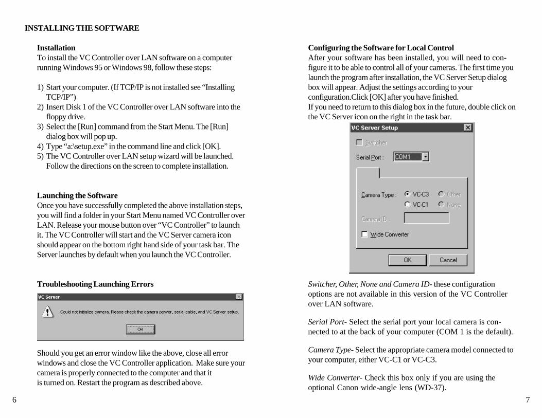
Configuring the Software for Local ControlAfter your software has been installed, you will need to con-figure it to be able to control all of your cameras. The first time youlaunch the program after installation, the VC Server Setup dialogbox will appear. Adjust the settings according to yourconfiguration.Click [OK] after you have finished.If you need to return to this dialog box in the future, double click onthe VC Server icon on the right in the task bar.
Switcher, Other, None and Camera ID- these configurationoptions are not available in this version of the VC Controllerover LAN software.
Serial Port- Select the serial port your local camera is con-nected to at the back of your computer (COM 1 is the default).
Camera Type- Select the appropriate camera model connected toyour computer, either VC-C1 or VC-C3.
Wide Converter- Check this box only if you are using theoptional Canon wide-angle lens (WD-37).
Configuring the Software for Remote ControlIf you are setting up a local camera that will be controlled by aremote site, (e.g. you have a security camera set up in one room inyour building which will be controlled from a remote computer), youonly need to run the VC Server and do NOT need the VC Control-ler open at the local end.Simply select [VC Server] in your [VC Controller over LAN]program folder on the local computer. This will allow the camera tobe controlled by the remote computer.
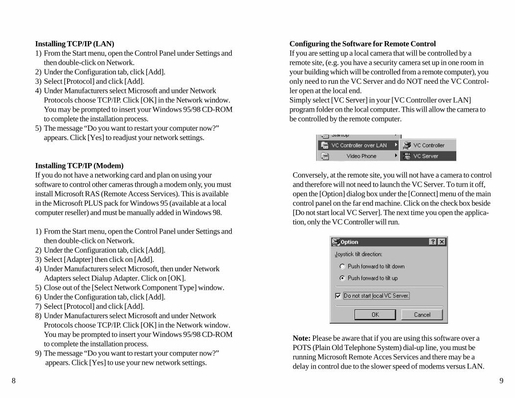
Conversely, at the remote site, you will not have a camera to controland therefore will not need to launch the VC Server. To turn it off,open the [Option] dialog box under the [Connect] menu of the maincontrol panel on the far end machine. Click on the check box beside[Do not start local VC Server]. The next time you open the applica-tion, only the VC Controller will run.
Note: Please be aware that if you are using this software over aPOTS (Plain Old Telephone System) dial-up line, you must berunning Microsoft Remote Acces Services and there may be adelay in control due to the slower speed of modems versus LAN.
8 9
Installing TCP/IP (LAN)1) From the Start menu, open the Control Panel under Settings and
then double-click on Network.2) Under the Configuration tab, click [Add].3) Select [Protocol] and click [Add].4) Under Manufacturers select Microsoft and under Network
Protocols choose TCP/IP. Click [OK] in the Network window.You may be prompted to insert your Windows 95/98 CD-ROMto complete the installation process.
5) The message “Do you want to restart your computer now?”appears. Click [Yes] to readjust your network settings.
Installing TCP/IP (Modem)If you do not have a networking card and plan on using yoursoftware to control other cameras through a modem only, you mustinstall Microsoft RAS (Remote Access Services). This is availablein the Microsoft PLUS pack for Windows 95 (available at a localcomputer reseller) and must be manually added in Windows 98.
1) From the Start menu, open the Control Panel under Settings andthen double-click on Network.
2) Under the Configuration tab, click [Add].3) Select [Adapter] then click on [Add].4) Under Manufacturers select Microsoft, then under Network
Adapters select Dialup Adapter. Click on [OK].5) Close out of the [Select Network Component Type] window.6) Under the Configuration tab, click [Add].7) Select [Protocol] and click [Add].8) Under Manufacturers select Microsoft and under Network
Protocols choose TCP/IP. Click [OK] in the Network window.You may be prompted to insert your Windows 95/98 CD-ROMto complete the installation process.
9) The message “Do you want to restart your computer now?” appears. Click [Yes] to use your new network settings.

If you decide to cancel the connect operation, you can use the StopConnecting tool bar button.
To close a connection, click on the Disconnect tool bar button.
You can connect to a local camera, either by entering yourcomputer’s IP address or by clicking on “local host” in theaddress window.
Additionally, the History function in the address window storespreviously contacted camera addresses to help make yourselection easier and faster. By dropping down the window youcan immediately connect to a frequently called camera.
Please be aware: Only one user can control a camera at a time.The last connection made will always override any previoususer’s connection and disconnect that user.
To connect to a remote or a local camera, you can either select[Connect] under the [Connect] Menu
or click on the [Connect] tool bar button.
The computer which is connected to the camera you would liketo control has an IP address. Enter it into the Address window.
To find your computer’s IP address:1. Right-click on your Network Neighborhood desktop icon and
select Properties.2. Select TCP/IP, then click Properties.3. The number displayed is your IP address.4. You will need to know the IP addresses of all the computers
connected to the cameras you want to access.
10 11
CONNECTING TO A CAMERA

MOVEMENT CONTROL FUNCTIONS
Pan, Tilt, Zoom and Home PositionThe VC Controller over LAN software offers you three differ-ent ways to control your communication camera’s basic move-ments. Pan, Tilt, Zoom and Return to the Home Position areoperable either through your mouse by clicking on the graphicbuttons of the VC Controller, through the Controller’s FinderWindow or through your computer keyboard.
Click on a VC Controller button to make the camera move inthe direction you desire, as noted below.
Tilt Up Zoom In
Home
Pan Left* Pan Right*
Tilt Down Zoom Out
*Pan Direction depends on the way the camera is facing. Please refer to page 12, “Setting the panning direction”.
You can also control the above features through the Finder Win-dow. The Finder Window displays a rectangle that changes positionand size when you drag it with the mouse. This rectangle reflects theframing of your video image and the pan and tilt angles of yourcamera, as well as the zoom position.
Pan/TiltRanges
Maximum Viewable Area
Setting the panning directionOnce you have connected to the camera you wish to control, youwill need to set the panning direction to reflect how the camera isfacing.
12 13
Angle of View
Normal: Camera is shooting the subject as if from your point of view.For example: If you had the camera in normal mode, when youpress the key, the camera pans left as in the image below.
Reverse: Camera is shooting you and you are the subject.For example: If you had the camera in reverse mode, when youpress the same key, the camera pans right.
Normal Reverse

Extended Camera OptionsYou can use the Extend button on the Main Control Panel togain access to several useful camera control options.
The pop-up menu displays four types of optional settings. Youcan change the zoom, shutter, pan and tilt speeds, as well aswhite balance, to suit your needs.
To change your camera’s angle of view, simply click on therectangle within the Finder Window and, while holding downthe mouse, drag it to a new position. The camera will move to viewthat area.
To adjust the zoom position, place your mouse at the edge ofthe rectangle. A double-sided arrow will appear. Click anddrag it to readjust the zoom. As the rectangle gets smaller, thecamera zooms in and, conversely, as it gets bigger, the camerazooms out.
To control your communication camera with the keys of yourkeyboard, use the up/down/right/left arrow keys or the numbers1,2,3,4,5 and 6 of the number keypad to go to any presets. Thenumber 7 key is for the Home Position and the + and - keys are forZoom In and Zoom Out. Remember to turn off the number lock sothat the keys can be activated for controlling the camera.
The Operate button (below the Controller buttons), can be usedto temporarily disable camera control and mute video images.
14 15

Zoom Speed: You can select either [Slow] or [Fast] for thezoom speed. Please refer to the chart below. The default settingdepends on the camera.
Shutter Speed: Select a shutter speed out of [Auto], [1/60] or[1/100]. The default speed depends on the camera.
Pan/Tilt Speed: Select either [Auto] or [Manual] speed.The default setting is [Auto].In the [Auto] mode, you have the choice of either [Slow],[Normal] or [Fast]. The default is [Normal].In [Manual] mode, you use a sliding bar to set both the Pan and Tiltspeeds and adjust their speeds along a gradated scale of 1-100.The default speed on both Pan and Tilt bars is 50. Please refer tothe chart below.
White Balance: There is no manual white balance setting,however, there is a choice between [Auto] and [Lock]. The defaultis [Auto]. Sometimes, though, if the lighting conditions suddenlychange, or if a monochrome subject is being shot, the color canlook unnatural. This is when you should implement the [Lock]setting, to prevent the current white balance setting from changing.
After you have made all the desired changes to the camerasettings, click the [Apply] button for them to be put into effect.Finally click the [Close] button to exit the Extended cameraOptions window.
16 17
Click on it again to deactivate back-light compensation.
Back-light CompensationWhen the strongest source of light is coming from behind thesubject you wish to view, making it seem too dark, you can turn onthe backlight compensation to see the subject better.
Click on the back-light button once to activate back-light compensation.
IMAGE CONTROL FUNCTIONS
Automatic and Manual FocusClick on the AF/MF... button to access the Focus Window.
Select [Auto] for auto focus and [Manual] to have more controlover the focus. In [Manual] mode, the Far button adjusts thecamera’s focus on a distant subject and the Near button sharpensthe focus on closer subjects.
Zoom SpeedTele Wide
SSN
NFF
Pan/Tilt Speed
Slow (S)Normal (N)
Fast (F)
Auto
Relationship between Zoom Speed Range and Pan/Tilt Speed

Preset MarksAs soon as you program any of the numbered preset buttons,its corresponding number is displayed in the Finder Window.You can easily verify a preset location and return the camera toany preset position by clicking on the numbered button. Whether ornot you program preset positions, you can click anywhere withinthe Finder and the camera will reposition itself accordingly.
19
Programming PresetsYou can program up to 6 presets which will store your preferredcamera positions, zoom positions and whether or not the back-lightcompensation is on or off. Doing so will allow you to reposition thecamera quickly and accurately when you click on any given presetbutton.
1) Adjust the camera position, zoom and back-light the wayyou want them.
2) Click the Preset Registration button. The button’s colorwill change to green, ready to accept a preset. (To cancel beforeselecting a preset, simply click the button again to turn the presetmode off).
3) Click on the numbered button (1-6) that you would like toprogram.
The color of that button will turn green and that button isnow programmed. Follow these steps to program each position.
*You can not overwrite presets. They must be removed first.
Deleting Presets1) Click on the Preset Deletion button. The button’s color
will change to green. (To cancel the operation and keep theprogrammed setting, click on the Deletion button again - thebutton will return to black and the setting will remain).
2) Click the programmed button that contains the information you would like to delete.
3) When the presets have been deleted, both the preset num-bered button and the Preset Deletion button will becomeblack again.
18
ADVANCED CONTROL OPTIONS

You can also identify your favorites by color*. Under the [View]menu click on [Properties] and then on [Setting...]. The [Color]dialog box will appear. Click on the color of your choice. When youclick [OK], the color will be saved with the favorite and will updatethe background color in the Finder.
You can click on the [Define Custom Colors] button to select a newcolor from the pop up color palette. Move the cursor over yourdesired color and click on that spot. The color will be added toyour [Custom Colors] menu.
*If you are using a version of Windows 95 earlier than version[4.00.950 B], see page 25.
21
FavoritesInstead of trying to remember the IP address for each camera youuse, you can assign it a more user-friendly name. To do this, openthe [Favorites] menu and select the option [Add to Favorites].Enter a name for your preferred camera and then the IP address(see page 10 for details) for the computer to which that camera isattached. Click the [OK] button to save this information.
If you decide to change the name or IP address of one of yourfavorites, go to the [Favorites] menu and click on [OrganizeFavorites].
The [Organize Favorites] box will pop up and you can changea name by highlighting it. The options to add a new name, delete acurrent name, edit a name in the list, or connect to one of thenamed cameras, are all possible through this window.
20
OTHER FUNCTIONS

Using a Joystick for camera controlIn the [Option] dialog box under the Connect menu, selecting thejoystick tilt direction sets the relationship between the camera andjoystick movements. The default setting is [Push forward to tilt up].
Please note: The direction in which the camera pans is also deter-mined by how the Pan Direction button in the Property box is set.See page 12, “Setting the panning direction”. Pushing buttons 1 and2 simultaneously returns the camera to the home position.
Zoom OutZoom In
23
Both the vertical and horizontal modes display all control options onthe face of the panel while the small and medium modes display onlythe more popularly used controls.
Additionally, under the view menu, there are three other op-tions you can hide from view or not. The tool bar will bevisible at the top of the Controller window when checked. Thestatus bar will be visible at the bottom when checked. The presetswill show up as numbers in the Finder area when checked. Theseoptions can be helpful in managing your desktop space.
22
Microsoft Sidewinder JoystickTM
Changing the Display of the Main PanelThere are four display options for the Main Panel:
Horizontal
Vertical
MediumSmall
Note: Please refer to the joystick manual for connecting andconfiguring a joystick with your computer.

Error MessagesIf either the remote or local camera Servers are not turned on(indicated by a small camera icon on the task bar in the right handof your screen), the message below will appear. You will need toclose the VC Controller over LAN software and restart the pro-gram and the Server. Make sure that the box [Do not start CameraServer] is left unchecked. This box is under the Connect menu ofthe main control panel, under [Options].
25
Messages displayed in status barThe status bar at the bottom of the VC Controller displays thecamera connection status. Below are four typical messages.
When the VC Controller and Server are ready to attempt connect-ing to a camera, this message appears in the status bar:
As the Controller attempts to connect to a camera, thismessage appears:
Once the VC Controller has connected to a camera successfully, itshows the name of the camera (or IP address) in the bar:
Once the connection to a camera is interrupted, this messageappears in the status bar:
24
MESSAGES
Other MessagesIf the VC Server was running, when you quit working with the LANsoftware, this message will appear when you go to close the VCController over LAN. Click [OK] to close the program.
Windows version [4.00.950] or [4.00.950 A] Users OnlyIf you are using a version of Windows 95 earlier than OSR2[4.00.950 B] you will experience the following:-After changing the color preference of a Favorite and you clickOK, the change is NOT made. If you click Cancel, a “Runtimeerror ‘48’:Error in loading DLL” message will appear. Furthermorethe application may unexpectedly quit.
How to check the version of Windows 95 you are using:Right mouse click on My Computer on your desktop. SelectProperties from the dropmenu.Your version of Windows 95 isdisplayed on the right under System. If it is version [4.00.950] or[4.00.950A] the above error will happen.
To fix this problem, you must install Internet Explorer v3.0 or later.Available free from Microsoft. (www.microsoft.com)

RS-232 Pin Out Diagrams
9-pin DSUB to 8-pin (VC-C3) Connection
Below is a cable pin out diagram of the cable required to controlthe Canon VC-C1 or VC-C3 camera from a computer with a9-pin serial port.
8-pin to 8-pin (VC-C3) Connection
Below is a cable pin out diagram of the cable required to controlthe Canon VC-C3 cameras from a computer with an 8-pin serialport.
27
Technical SupportIf you experience a problem with the installation or operation of theVC Controller over LAN Software, you may write,e-mail or call Canon USA, Inc. Technical support is availablebetween the hours of 9:00 A.M. and 5:00 P.M. EST.Please have the following information available beforecontacting us for technical support.
1. The manufacturer and model of your computer. 2. The version of your VC Controller over LAN Software.
(Please see below for how to find this information.) 3. The amount of memory (RAM) in you computer. 4. The version of Windows you are using.
Canon USA, Inc.Visual Communication Systems Division1 Canon Plaza, Bldg. BLake Success, NY 11042Tel (516) 328-5960Fax (516) 328-5959E-mail: [email protected]
By selecting [About VC Controller] under the Help menu of themain control panel, the information window will open. The version of your software will be listed here.
26
APPENDIX A APPENDIX B

NOTES
28