vcon brochure 2011 final - gepco brand and gepco ® brand multi-channel video snake cable, v-con...
TRANSCRIPT


www.gepco.com | 800.966.0069
I N T R O D U C T I O N1
CONNECTORS
Distribution Racks
Breakout Boxes
Cable Assemblies
3 - 6
7 - 8
9 - 10
11 - 12
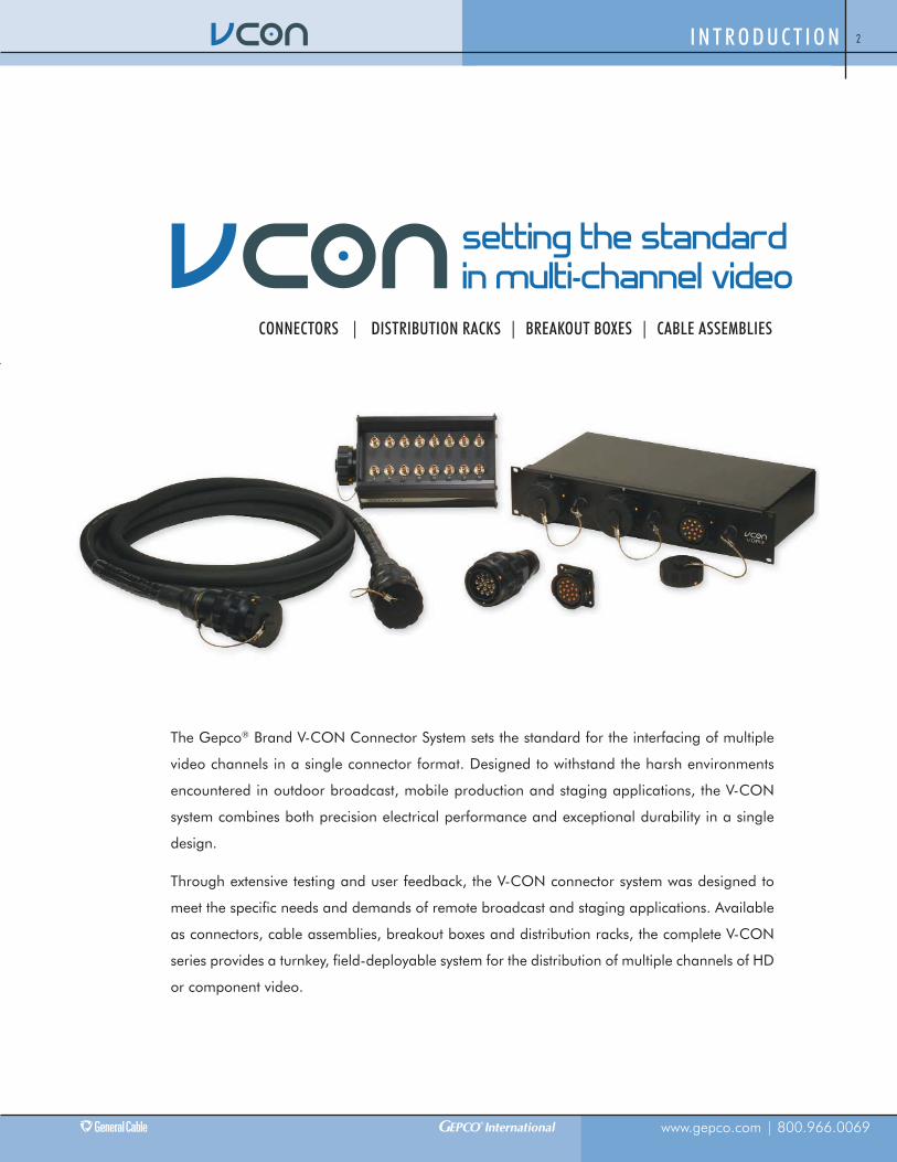
The Gepco® Brand V-CON Connector System sets the standard for the interfacing of multiple
video channels in a single connector format. Designed to withstand the harsh environments
encountered in outdoor broadcast, mobile production and staging applications, the V-CON
system combines both precision electrical performance and exceptional durability in a single
design.
Through extensive testing and user feedback, the V-CON connector system was designed to
meet the specific needs and demands of remote broadcast and staging applications. Available
as connectors, cable assemblies, breakout boxes and distribution racks, the complete V-CON
series provides a turnkey, field-deployable system for the distribution of multiple channels of HD
or component video.
www.gepco.com | 800.966.0069
I N T R O D U C T I O N 2
CONNECTORS | DISTRIBUTION RACKS | BREAKOUT BOXES | CABLE ASSEMBLIES
setting the standardin multi-channel video

www.gepco.com | 800.966.0069
C O N N E C T O R S3
CONNECTORS
Setting the standard in multi-channel video con-nectors, the Gepco® Brand V-CON connector of-fers a convenient, reliable and durable interfaceformat for high-density video applications. De-signed for exceptional durability, the V-CON wasspecifically engineered for outdoor broadcast, mo-bile production and staging applications. It features anall-metal body, locking set-screw and integrated cord grip, all in a com-pletely weather-tight design.
Electrically, the V-CON has the bandwidth and performance for bothmulti-channel HD and component video applications. Through a con-figurable insert, the V-CON is available in three-, four-, five- or six-channel versions that may be typically used in component videoapplications, while the 10-, 12- or 16-channel versions can be usedfor high-density, multi-channel HD video streams. The low insertionloss and 3 GHz bandwidth of the V-CON allows it to be used in uncom-pressed HD serial digital applications. The V-CON coaxial elementsare constructed from stainless steel and 50 micron gold-plated contactsto provide corrosion resistance and exceptionally long mating life.
Configurable to 3, 4, 5, 6, 10, 12, or 16 Channels
Extra-Rugged, All-Metal Body with Set-Screw
Unique Keyway Style for Each Configuration
50 Micron Gold-Plated and Stainless Steel Contacts
Weather Resistant
3 GHz Bandwidth
Uncompressed HD-SDI or Component Video
Integrated Cord Grip
Additional Specifications
Structural Return Loss -15dB, 1 MHz-3 GHz
Insertion Loss 0.25 dB
Cable Termination Type VDM230 Type 23 AWG Solid or VDM250 Type 25 AWG Stranded
V-CON CONNECTORS
Part Number # of Channels Gender Type Shell Size Maximum Cable Diameter
VCON16FC 16 Female Cable Mount Large - Type 36 0.885”
VCON16MP 16 Male Panel Mount Large - Type 36 0.885”
VCON12FC 12 Female Cable Mount Large - Type 36 0.885”
VCON12MP 12 Male Panel Mount Large - Type 36 0.885”
VCON10FC 10 Female Cable Mount Large - Type 36 0.885”
VCON10MP 10 Male Panel Mount Large - Type 36 0.885”
VCON6FC 6 Female Cable Mount Small - Type 24 0.625”
VCON6MP 6 Male Panel Mount Small - Type 24 0.625”
VCON5FC 5 Female Cable Mount Small - Type 24 0.625”
VCON5MP 5 Male Panel Mount Small - Type 24 0.625”
VCON4FC 4 Female Cable Mount Small - Type 24 0.625”
VCON4MP 4 Male Panel Mount Small - Type 24 0.625”
VCON3FC 3 Female Cable Mount Small - Type 24 0.625”
VCON3MP 3 Male Panel Mount Small - Type 24 0.625”

www.gepco.com | 800.966.0069
C O N N E C T O R S 4
O-ring SealFront o-ring gasket seals themated connector from water ormoisture ingress.
Captive ContactCenter pin or socket captivates in dielectric for asecure and positive fit.
Stainless Steel and Gold-Plated ContactsCoaxial contacts are manufactured from stainlesssteel and 50 micron gold-plated brass to ensurecorrosion resistance and exceptional mating life.Coaxial contact bodies fully captivate in connectorinsert.
Three-Point Lock RingProvides an exceptionally securemating action.
Set-ScrewsCable mount type V-CON connectors feature twoset-screws, 180 degrees apart, for a locking fitthat prevents accidental backshell loosening.
3 GHz Coaxial ElementsV-CON series contacts feature low insertion-loss,low return-loss and a 3 GHz bandwidth for un-compressed HD video applications.
Integrated Cord GripAn integrated compression gland provides strainrelief and a weather-resistant seal. The internalwidth of the rear shell allows for a metal meshcord grip to be used for additional strain andbend relief.
Configurable InsertThe insert can be configured for 10-, 12- or 16-channel versions in the large type 36 V-CONshell, or for 3-, 4-, 5- or 6-channel versions in thesmall type 24 V-CON shell.
All-Metal ShellThe V-CON backshell, backnut and lock ring areconstructed from hard-anodized aluminum for ex-ceptional durability.
Unique Keyway OrientationEach configuration (channel type) has a uniquekeyway location to prevent accidental mating be-tween different configuration styles.
Rear View of Panel MountConnector Male Plug
Rear View of Cable MountConnector Female Socket
16-Channel Pinout Information Crimp Tool Information
Inserts are marked for channel configuration.
Connector for Panel MountPin: Paladin® 1442 with GEP-VAG-P Alignment InsertSleeve: ADC® WT-2 or WT-3 (WD-2 DIE), Paladin 1389 (DIE 2699) 1300 Series, Paladin 1669 (DIE2683)1600 Series, Paladin 8049 (DIE2699) CrimpALL Series, Kings® KTH-1000 (KTH-2025 DIE)
Connector for Cable MountPin: Paladin 1442 with GEP-VAG-S Alignment InsertSleeve: ADC WT-2 or WT-3 (WD-2 DIE), Paladin 1389 (DIE 2699) 1300 Series, Paladin 1669 (DIE2683)1600 Series, Paladin 8049 (DIE2699) CrimpALL Series, Kings KTH-1000 (KTH-2025 DIE)
ADC is a registered trademark of ADC Telecommunications, Inc. Kings is a registered trademark of Kings Electronics Company, Inc. Paladin is a registered trademark of Greenlee Textron, Inc.

www.gepco.com | 800.966.0069
C O N N E C T O R S5
CONNECTORS: drawings
3-6 Channels: Panel Mount
Other Insert Configurations
Front View: 6 ChannelsSide View
Side View
3-6 Channels: Cable Mount
10-16 Channels: Panel Mount
10-16 Channels: Cable Mount
Front View: 16 ChannelsSide View
Front View: 16 ChannelsSide View
3 Channels
Front View: 6 Channels
4 Channels 5 Channels
3 Channels 4 Channels 5 Channels
10 Channels 12 Channels
10 Channels 12 Channels
Other Insert Configurations
Other Insert Configurations
Other Insert Configurations

www.gepco.com | 800.966.0069
C O N N E C T O R S 6
connectors: Accessories & Tools
Part Number Gender Description
VTE Male or Female Extraction Tool
VTI Male or Female Insertion Tool
PA1442 Male or Female 8-Way Indent Crimp Tool
VAG-P Male Alignment Guide for Crimp Tool
VAG-S Female Alignment Guide for Crimp Tool
VCON36DCP Male - Large Type 36 Panel Mount Dust Cap for 10, 12, or 16 Channels
VCON24DCP Male - Small Type 24 Panel Mount Dust Cap for 3, 4, 5, or 6 Channels
VCON36DCR Female - Large Type 36 Cable Mount Dust Cap for 10, 12, or 16 Channels
VCON24DCR Female - Small Type 24 Cable Mount Dust Cap for 3, 4, 5, or 6 Channels
4426-018 Male or Female - Large Type 36 0.875” Max Cable Diameter
4426-017 Male or Female - Large Type 36 0.750” Max Cable Diameter
4426-016 Male or Female - Large Type 36 0.625” Max Cable Diameter

www.gepco.com | 800.966.0069
D I S T R I B U T I O N R A C K S7
The V-CON series distribution racks offer a convenient and flexible so-lution for the distribution of multiple coaxial channels in a permanent-installation application. Ideal for junction boxes, truck I/O panels,control rooms or staging applications, the V-CON series is available ina variety on configurations and sizes. Each contact of the V-CON iswired out to a BNC female connector on the back panel for up to a totalof 160 channels in the 10x16 version. Available with three, five or 10V-CON connectors, each V-CON connector can be ordered as athree-, four-, five-, six-, 10-, 12- or 16-channel version.
Available in 3, 5, or 10 V-CON Multi-Pin Versions
Option of 3, 4, 5, 6, 10, 12 or 16 Channels per V-CON
3 GHz Bandwidth
Uncompressed HD-SDI or Component Video
Breaks Out V-CON Multi-Pin to BNCs
Includes Weather-Tight V-CON Dust Caps
4RU or 2RU Rack Height
distribution racks
V-CON DISTRIBUTION RACKS
Part Number # of V-CON Connectors # of Channels/Multi-Pin Connector Rack Unit Height V-CON Gender BNC Gender
VDR10* 10 10, 12, 16 4 Male - Large Type 36 Female
VDR5* 5 10, 12, 16 2 Male - Large Type 36 Female
VDR5*S 5 3, 4, 5, 6 2 Male - Small Type 24 Female
VDR3* 3 10, 12, 16 2 Male - Large Type 36 Female
VDR3*S 3 3, 4, 5, 6 2 Male - Small Type 24 Female
* = Number of Channels per V-CON

www.gepco.com | 800.966.0069
D I S T R I B U T I O N R A C K S 8
Rear ViewFront View
VDR316
VDR516
Rear ViewFront View
Rear ViewFront View
VDR1016
www.gepco.com | 800.966.0069
B R E A KO U T B O X E S9
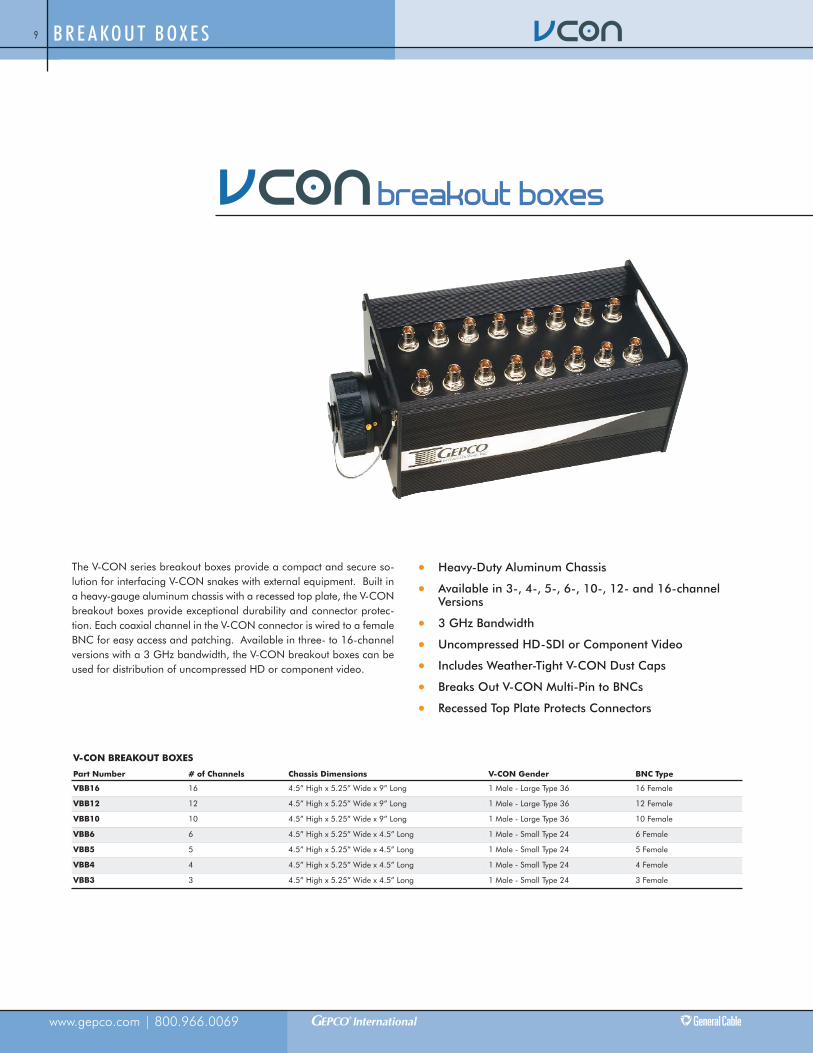
The V-CON series breakout boxes provide a compact and secure so-lution for interfacing V-CON snakes with external equipment. Built ina heavy-gauge aluminum chassis with a recessed top plate, the V-CONbreakout boxes provide exceptional durability and connector protec-tion. Each coaxial channel in the V-CON connector is wired to a femaleBNC for easy access and patching. Available in three- to 16-channelversions with a 3 GHz bandwidth, the V-CON breakout boxes can beused for distribution of uncompressed HD or component video.
Heavy-Duty Aluminum Chassis
Available in 3-, 4-, 5-, 6-, 10-, 12- and 16-channelVersions
3 GHz Bandwidth
Uncompressed HD-SDI or Component Video
Includes Weather-Tight V-CON Dust Caps
Breaks Out V-CON Multi-Pin to BNCs
Recessed Top Plate Protects Connectors
breakout boxes
V-CON BREAKOUT BOXES
Part Number # of Channels Chassis Dimensions V-CON Gender BNC Type
VBB16 16 4.5” High x 5.25” Wide x 9” Long 1 Male - Large Type 36 16 Female
VBB12 12 4.5” High x 5.25” Wide x 9” Long 1 Male - Large Type 36 12 Female
VBB10 10 4.5” High x 5.25” Wide x 9” Long 1 Male - Large Type 36 10 Female
VBB6 6 4.5” High x 5.25” Wide x 4.5” Long 1 Male - Small Type 24 6 Female
VBB5 5 4.5” High x 5.25” Wide x 4.5” Long 1 Male - Small Type 24 5 Female
VBB4 4 4.5” High x 5.25” Wide x 4.5” Long 1 Male - Small Type 24 4 Female
VBB3 3 4.5” High x 5.25” Wide x 4.5” Long 1 Male - Small Type 24 3 Female

www.gepco.com | 800.966.0069
B R E A KO U T B O X E S 10
Side View
Top View
Top View
Top View
Side View
Side View
VBB16
VBB10
VBB5

www.gepco.com | 800.966.0069
C A B L E A S S E M B L I E S11
V-CON terminated cable assemblies offer an extremely rugged, com-pact and weather-resistant portable interconnect system for HD or com-ponent video applications. Built with the Gepco® Brand V-CONconnector and Gepco® Brand multi-channel video snake cable, V-CONcable assemblies can be custom ordered in three- to 16-channel versions.
In addition to the durability provided by the internal strain relief, metalcord grip and gaskets of the V-CON design, the connector is alsosealed with an overbody, epoxy-lined heat shrink for additional protec-tion. The video snake cables utilize miniature, high bandwidth, gas-in-jected coaxial elements that are jacketed with an overall,weather-resistant TPE jacket.
The combined materials and termination methods used in the V-CONcable assemblies create the most durable and convenient multi-channelvideo snake system for broadcast and hostile environment applications.
Available in 3-, 4-, 5-, 6-, 10-, 12- or 16-ChannelVersions
Extra-Rugged, All-Metal Body with Set-Screw
Heavy-Duty TPE Cable Jacket
50 Micron Gold-Plated and Stainless Steel Contacts
3 GHz or 1 GHz Bandwidth
Weather Resistant
Uncompressed HD-SDI or Component Video
Cord Grip with Overbody Heat Shrink
cable assemblies
V-CON CABLE ASSEMBLIES
Part Number # of Channels V-CON Gender Cable Type Total Bandwidth Applications
VMC16-length 16 Female - Large Type 36 (Both Ends) VS16230 3 GHz Multi-Channel HD
VMC12-length 12 Female - Large Type 36 (Both Ends) VS12230 3 GHz Multi-Channel HD
VMC10-length 10 Female - Large Type 36 (Both Ends) VS10230 3 GHz Multi-Channel HD
VMC6-length 6 Female - Small Type 24 (Both Ends) RGBHVC250 1 GHz Component Video
VMC5-length 5 Female - Small Type 24 (Both Ends) VS5230 3 GHz Multi-Channel HD, Component Video
VMC5A-length 5 Female - Small Type 24 (Both Ends) RGBSC250 1 GHz Component Video
VMC4A-length 4 Female - Small Type 24 (Both Ends) RGBS250 1 GHz Component Video
VMC3A-length 3 Female - Small Type 24 (Both Ends) RGB250 1 GHz Component Video
Fanouts available as special order.

www.gepco.com | 800.966.0069
C A B L E A S S E M B L I E S 12
All-Metal Shell with Set-ScrewsCable mount type V-CON connectors feature twoset-screws, 180 degrees apart, for a locking fitthat prevents accidental backshell loosening. TheV-CON backshell, backnut and lock ring are con-structed from hard-anodized aluminum for excep-tional durability.
Cord Grip with Overbody Heat ShrinkIn addition to the internal V-CON strain relief,cable assemblies feature a metal mesh cord gripfor additional bend and strain relief. The entirerear portion of the connector is also sealed withan overbody, epoxy-lined heat shrink for excep-tional weather resistance and durability.
Precision HD Coax SnakeHigh-definition V-CON cable assemblies are con-structed from Gepco VS230 series video snakecable. The VS230 series features miniature 23AWG solid conductors, gas-injected dielectrics, a4.5 GHz bandwidth for uncompressed HD for-mats, and a durable, all-weather TPE masterjacket. For component video applications, theRGB 25 AWG stranded series is also available.
Cable Usedin Assembly
# ofChan. Conductors
NominalOD Imped.
Return Loss(100 kHz-1 GHz),(1 GHz-4.5 GHz) Capac.
Cond. DCRper Mft/ShieldDCR per Mft
Vel.ofProp.
Attenuation (dB per 100ft)
1MHz
10MHz
71.5MHz
135MHz
270MHz
360MHz
720MHz
1GHz
1.5GHz
3GHz
4.5GHz
VS16230 1623 AWGSolid BC
.885” 75 S(+/-3)
>23dB, >21dB 16.5 pF/ft 20.3 S/2.7 S 82% 0.38 1.19 3.01 3.80 5.40 6.18 9.30 10.5 13.0 18.5 22.8
VS12230 1223 AWGSolid BC
.800” 75 S(+/-3)
>23dB, >21dB 16.5 pF/ft 20.3 S/2.7 S 82% 0.38 1.19 3.01 3.80 5.40 6.18 9.30 10.5 13.0 18.5 22.8
VS10230 1023 AWGSolid BC
.785” 75 S(+/-3)
>23dB, >21dB 16.5 pF/ft 20.3 S/2.7 S 82% 0.38 1.19 3.01 3.80 5.40 6.18 9.30 10.5 13.0 18.5 22.8
RGBHVC250 625 AWG (7x33)Stranded BC
.575” 75 S(+/-3)
>23dB, ---- 16.5 pF/ft 30.0 S/4.8 S 82% 0.47 1.43 3.45 4.61 6.46 7.48 10.8 12.8 ---- ---- ----
VS5230 523 AWGSolid BC
.570” 75 S(+/-3)
>23dB, >21dB 16.5 pF/ft 20.3 S/2.7 S 82% 0.38 1.19 3.01 3.80 5.40 6.18 9.30 10.5 13.0 18.5 22.8
RGBSC250 525 AWG (7x33)Stranded BC
.560” 75 S(+/-3)
>23dB, ---- 16.5 pF/ft 30.0 S/4.8 S 82% 0.47 1.43 3.45 4.61 6.46 7.48 10.8 12.8 ---- ---- ----
RGBS250 425 AWG (7x33)Stranded BC
.470” 75 S(+/-3)
>23dB, ---- 16.5 pF/ft 30.0 S/4.8 S 82% 0.47 1.43 3.45 4.61 6.46 7.48 10.8 12.8 ---- ---- ----
RGB250 325 AWG (7x33)Stranded BC
.460” 75 S(+/-3)
>23dB, ---- 16.5 pF/ft 30.0 S/4.8 S 82% 0.47 1.43 3.45 4.61 6.46 7.48 10.8 12.8 ---- ---- ----
CABLE ELECTRICAL SPECIFICATIONS
Serial Digital Coax Distances Channel Color Codes
Maximum values represent the approximate range atwhich the bit error rate “cliff region” will occur. Individualsystem performance will vary.
Cable VS Series
Channel # Color1 Brown2 Red3 Orange4 Yellow5 Green6 Blue7 Violet8 Gray9 White10 Black11 Tan12 Pink13 Neon Orange14 Pumpkin 15 Lime Green16 Teal
Cable RGB Series
Channel # Color1 Red2 Green3 Blue4 Yellow5 White6 Black

www.gepco.com | 800.966.0069
PA R T N U M B E R I N D E X13
Part Number Index4426-016 Page 6
4426-017 Page 6
4426-018 Page 6
PA1442 Page 6
VAG-P Page 6
VAG-S Page 6
VBB10 Page 9
VBB12 Page 9
VBB16 Page 9
VBB3 Page 9
VBB4 Page 9
VBB5 Page 9
VBB6 Page 9
VCON10FC Page 3
VCON10MP Page 3
VCON12FC Page 3
VCON12MP Page 3
VCON16FC Page 3
VCON16MP Page 3
VCON24DCP Page 6
VCON24DCR Page 6
VCON36DCP Page 6
VCON36DCR Page 6
VCON3FC Page 3
VCON3MP Page 3
VCON4FC Page 3
VCON4MP Page 3
VCON5FC Page 3
VCON5MP Page 3
VCON6FC Page 3
VCON6MP Page 3
VDR10* Page 7
VDR3* Page 7
VDR3*S Page 7
VDR5* Page 7
VDR5*S Page 7
VMC10-length Page 11
VMC12-length Page 11
VMC16-length Page 11
VMC3A-length Page 11
VMC4A-length Page 11
VMC5A-length Page 11
VMC5-length Page 11
VMC6-length Page 11
VTE Page 6
VTI Page 6

All information in this catalog is presented solely as a guide to product selection and is believed to be reliable. All
printing errors are subject to correction in subsequent releases of this catalog. Although General Cable has taken
precautions to ensure the accuracy of the product specifications at the time of publication, the specifications of all
products contained herein are subject to change without notice.
GENERAL CABLE and GEPCO® BRAND are registered trademarks of General Cable Technologies Corporation.
©2011. General Cable Technologies Corporation.
Highland Heights, KY 41076
All rights reserved. Printed in USA.

Headquarters and Manufacturing
1770 Birchwood Avenue
Des Plaines, IL 60018
800.966.0069
P. 847.795.9555
F. 847.795.8770
Branch Office and Distribution Center
1000 N. Lake Street
Burbank, CA 91502
P. 818.569.5222
F. 818.569.5226
Distribution Center
Clifton, NJ
Form No. GEP-0002-R0811