vectorized production path tracing - dreamworks animation · 2018-07-12 · vectorized production...
TRANSCRIPT

Vectorized Production Path TracingMark Lee
DreamWorks AnimationBrian Green
DreamWorks Animation
Feng XieDreamWorks Animation
Eric TabellionDreamWorks Animation
Figure 1: This scene of Poppy singing is from the opening sequence of the movie “Trolls”. We have rendered it here with MoonRay, our vectorizedproduction path tracing system. The scene uses over 7 GB of geometry with 9.1 million curves, and an average of 20 control vertices per curve; thecharacters have complex shading networks and use around 1.3 GB of unique textures. The SIMD utilization provided a 5× speedup for the shadingand a 3× speedup for the path integration portions of the frame.
ABSTRACTThis paper presents MoonRay, a high performance production ren-dering architecture using Monte Carlo path tracing developedat DreamWorks Animation. MoonRay is the first production pathtracer, to our knowledge, designed to fully leverage Single Instruc-tion/Multiple Data (SIMD) vector units throughout. To achieve highSIMD efficiency, we employ Embree for tracing rays and vectorizethe remaining compute intensive components of the renderer: theintegrator, the shading system and shaders, and the texturing en-gine. Queuing is used to help keep all vector lanes full and improvedata coherency.We use the ISPC programming language [Intel 2011;Pharr and Mark 2012] to achieve improved performance across SSE,AVX/AVX2 and AVX512 instruction sets. Our system includes twofunctionally equivalent uni-directional CPU path tracing imple-mentations: a C++ scalar depth-first version and an ISPC vectorizedbreadth-first wavefront version. Using side by side performancecomparisons on complex production scenes and assets we show
HPG ’17, July 28-30, 2017, Los Angeles, CA, USA© 2017 Copyright held by the owner/author(s). Publication rights licensed to Associa-tion for Computing Machinery.This is the author’s version of the work. It is posted here for your personal use. Notfor redistribution. The definitive Version of Record was published in Proceedings ofHPG ’17, July 28-30, 2017 , https://doi.org/10.1145/3105762.3105768.
our vectorized architecture, running on AVX2, delivers betweena 1.3× to 2.3× speed-up in overall render time, and up to 3×, 6×,and 4×, speed-ups within the integration, shading, and texturingcomponents, respectively.
CCS CONCEPTS• Computing methodologies→ Rendering; Ray tracing;
KEYWORDSComputer Graphics, Monte Carlo, Path Tracing, Production Ren-dering, Vectorization
ACM Reference format:Mark Lee, Brian Green, Feng Xie, and Eric Tabellion. 2017. VectorizedProduction Path Tracing. In Proceedings of HPG ’17, Los Angeles, CA, USA,July 28-30, 2017, 11 pages.https://doi.org/10.1145/3105762.3105768
1 INTRODUCTIONOver the past decade, research in high performance path tracinghas greatly reduced the cost per ray and the time to build efficientacceleration structures [Ernst and Greiner 2008; Parker et al. 2010;

HPG ’17, July 28-30, 2017, Los Angeles, CA, USA Lee et al.
Figure 2: “Trolls” environment Bergen Town, Astrid and an environment set piece called Hotspur from the movie “How to Train Your Dragon 2”,rendered with vectorized MoonRay. Bergen Town uses over 360 MB of geometry mostly consists of subdivision meshes and 1.1 GB of textures;Astrid uses over 1.67 GB of geometry and 1.34 GB of textures; Hotspur uses 1.38 GB of geometry and 11.1 GB of textures. Astrid’s hair alone hasover 100K curves with an average of 45 control vertices per curve. There are over 3.5 million curves for Astrid’s entire setup including hood fur,arm band fur, fur on her dress and soft skin fuzz, eyebrows and eyelashes. Vectorized MoonRay delivers a 1.6× to 2.3× speed up on total rendertime for these 3 scenes, with performance gains in shading, texturing and integration ranging from 2× to over 4×.
Wald 2007; Wald et al. 2014]. During the same period, large im-provements in hardware have vastly increased the number of CPUcores and the amount of memory available on commodity hard-ware. This overall increase in computational power has enabledproduction rendering systems to move away from the rasterization-based Reyes architecture [Cook et al. 1987], and evolve towardsphysically-based path tracing algorithms, the most commonly usedapproach being uni-directional path tracing [Kajiya 1986] with nextevent prediction [Pharr et al. 2016].
Path tracing is an inherently parallel algorithm and path tracingrenderers have been able to exploit the growing number of CPUcores with relative ease. Each of these cores however devotes anon-trivial on-die area to supporting the vector (SIMD) processingof data. This should allow significantly higher throughput in theory,orthogonal to gains from multi-threading. However, no productionrenderer to date has been designed to exploit vector hardwarethroughout the whole system. So although path tracing itself istrivially parallelizable, unfortunately, it is not trivially vectorizable.In the context of a CPU based production renderer, the quest for fullvectorization raises many questions... How do we access the vectorhardware effectively? How do we map the path tracing algorithminto this domain whilst maintaining the flexibility required forproduction? How do we gather batches of work to keep the vectorhardware busy? How do we keep memory accesses coherent andavoid scatters and gathers? How do we minimize vector code flowdivergence? And if we do satisfactorily solve these problems, thequestion then becomes: do the potential performance benefits gainedoutweigh the extra work required to harness the vector hardware?
The main contribution of this paper is an attempt to shed lighton these questions. In doing so, we introduce MoonRay, which toour knowledge, is the first full featured film production rendererdesigned to leverage SIMD vectorization throughout the wholesystem. We give an overview of the scalar and vectorized variantsof MoonRay in Section 3.
In addition to being fully vectorized, MoonRay uses various op-timization techniques commonly used in the games industry toachieve additional speedups. These include applying Data Oriented
Design principles [Acton 2014] and a somewhat constrained ap-proach to thread locking and memory allocation. It’s worth clari-fying that these optimizations are orthogonal to any vectorizationspeedups, and so benefit the both scalar and vectorized variants ofthe renderer. We elaborate on these details in Section 4.
In Section 5 we describe the underlying building blocks usedto facilitate vectorized processing, in particular our approach toqueuing and sorting the rays/samples, and the array-of-structures(AOS) to structure-of-arrays (SOA) transposition system we use tomap each of these onto its own dedicated vector lane.
Embree [Wald et al. 2014] is employed for all ray intersections,which is already well vectorized internally. We have identified 3additional components where a significant percentage of rendertime is spent, and are amenable to vectorization: shading, texturing,and integration. These are the areas we’ve specifically focused on,such that a single ray or sample is mapped to a single vector lanethroughout. In Section 6 we cover the design and implementationspecifics of each of these.
Finally, in Section 7 we provide detailed performance compar-isons between our scalar and vectorized implementations of therenderer.
2 PREVIOUS WORKMuch essential work has been devoted in the past decade to ac-celerating ray tracing [Ernst and Greiner 2008], to handling curveprimitive ray traversal and intersection [Nakamaru and Ohno 2002;Woop et al. 2014] and to quickly building good quality accelerationstructures [Wald 2007]. Many papers also focused on acceleratingthe tracing of incoherent rays [Aila and Karras 2010], either viaSIMD single ray traversal [Wald et al. 2008], packet tracing [Benthinet al. 2012; Garanzha and Loop 2010] or ray stream tracing [Hobe-rock et al. 2009; Tsakok 2009]. The OptiX ray tracing engine [Parkeret al. 2010] provides a high performance ray tracing API for GPUarchitecture, whilstMoonRay uses Embree [Wald et al. 2014], whichhas state of the art ray tracing kernels with good SIMD utilizationfor single ray, ray packets and ray stream tracing computationon the CPU. As a result, our performance focus on MoonRay is

Vectorized Production Path Tracing HPG ’17, July 28-30, 2017, Los Angeles, CA, USA
Figure 3: Conventional path tracing on the left vs. vectorized path tracing on the right. The various queues in the vectorized implementationcan be seen on the above right. All queues with the exception of the shade queue are thread local and allocated per thread. Each queue has anassociated “handler”, represented by dashed lines to gray boxes, which process the entries in a queue after it fills up. Each handler can add furtherentries to other queues, as indicated by the solid black lines. All of the shading, texturing, and integration takes place inside the of the ShadeQueue Handler.
on accelerating all the other components needed in a productionpath tracing system, using coherent rendering and vectorizationtechniques.
Coherent rendering for ray tracing was introduced by Hanra-han [Hanrahan 1986], and further developed by Pharr et al. [Pharret al. 1997]. It is a necessary step in attempting to achieve goodmemory locality of reference and enable optimizations relying oncaching coherence, among others. To this end, there has been muchwork in hybrid rendering systems [Pantaleoni et al. 2010] that relyon spatial sorting, level of detail (LOD) selection and streamingin order to efficiently pre-compute spherical occlusion of out-of-core scenes on the GPU. Similarly, Kontkanen et al. [Kontkanenet al. 2011] performs clustering of spatial subdivision data structurenodes into coherent sub-trees, to accelerate the out-of-core traver-sal algorithm used in computing point based global illumination.More recently, Disney’s Hyperion [Eisenacher et al. 2013] demon-strated good geometry and texturing coherence via ray and hitpoint sorting, however their work does not exploit data parallelismor vectorization.
Laine et al. [Laine et al. 2013] describe a Single Instruction/MultipleThreads (SIMT) wavefront path tracing approach on the GPU, inorder to reduce the divergence and register pressure encounteredwhen naively executing large path tracing and shading kernels.Their system shows great promise when executing vectorized com-plex material shaders, but lacks many abilities of a productionrendering system. Iray [Keller et al. 2017], which is built on top ofOptiX, demonstrates what a more fully featured path tracer mightlook like in the GPU domain. In the work perhaps most closelyrelated to ours, Áfra et al. [Áfra et al. 2016] study the impact of hitpoint sorting and ray batch sizing to reduce CPU SIMD divergencein manually vectorized shaders. Their system achieves high SIMD
utilization similar to ours while rendering complex scenes. Oursystem extends this general type of approach to the whole ray-tracing pipeline and also supports a number of additional featureswhich are essential for production rendering such as path splittingwith Russian Roulette [Vorba and Křivánek 2016], out-of-core mip-mapped lazy texture access based on ray differentials [Gritz 2007],and arbitrary shader graphs assembled at runtime.
3 OVERVIEWMoonRay is a production renderer that supports subdivision sur-faces, polygonmeshes and curve primitives. It can coherently accessvery large amounts of out-of-core texture data, using UDIM UVmapping [Seymour 2014] and mip-mapping driven by ray differen-tials tracked along each path. MoonRay has a complete proceduralplugin API for rendering application, geometry procedural andsurface shader development. We have used these APIs to developfur/hair geometry procedurals, Alembic [Imageworks 2017] load-ers and a complete set of lights, materials and texture shaders forfeature animation.
Image generation in MoonRay is separated into two distinctphases which we will refer to in the remainder of this paper:
(1) The preparation phase is where we initially load the scenedescription, load and generate geometry assets by runningprocedural plug-ins, build the ray tracing acceleration struc-tures and setup other data structures required for rendering.
(2) The rendering phase is where we compute pixel values bytracing paths, running shaders and executing Monte Carlosampling and integration calculations at every ray hit alongthe paths. This is the compute-intensive phase, which is thefocus of our vectorization architecture.

HPG ’17, July 28-30, 2017, Los Angeles, CA, USA Lee et al.
Conceptually, the rendering phase proceeds as follows. The im-age is partitioned into small square pixel buckets from which pri-mary rays leaving the camera are computed and traced throughthe scene. Ray hits trigger the execution of a pre-assigned surfaceshader. The latter returns a Bsdf closure to the integrator, whichcontains a list of Bsdf lobes describing an arbitrarily complex sur-face or curve reflectance model that can be importance sampled.A pre-assigned light-set which can also be importance sampled islooked up, describing the full list of lights affecting the given rayhit.
The integrator then performs sampling decisions and calcula-tions. We build upon robust uni-directional path tracing techniquesusing next event estimation of direct illumination and multipleimportance sampling (MIS), combined with path splitting and Rus-sian Roulette [Veach and Guibas 1995]. In our implementation,paths are split into sub-paths based on explicit user control andthe paths with low importance are culled in a statistically unbi-ased way. Samples that pass the culling are traced further into thescene, either for testing occlusion or for continuing paths leadingto path tracing recursion. Path splitting and Russian Roulette workhand-in-hand to semi-automatically adjust the sampling densitywhen estimating parts of the high dimensional integral in variousareas of the scene. This typically leads to a sizeable sample cullingrate and consequently an increased percentage of time spent in theintegrator.
MoonRay contains two fully functional implementations of theaforementioned path tracing algorithm as illustrated in Figure 3.The scalar code-path uses parallel processing of pixel buckets andeach thread traces paths depth-first all the way with explicit recur-sion, before the next camera sample is processed. The vectorizedcode-path, on the other hand, processes batches of samples in wave-fronts in breadth-first order, using multiple queues to track raystate. Queue entries are processed in parallel, which leads to addingentries into down-stream queues. To avoid dependencies betweenqueues, the vectorized breadth-first implementation is a fully feed-forward pipeline and radiance contributions are decomposed asdescribed in Pharr et al. [Pharr et al. 1997]. ISPC [Intel 2011; Pharrand Mark 2012] is a C-like language from Intel which makes iteasier to write code targeting SIMD hardware. It hides the detailsof the underlying vector instruction set and internally generatesthe necessary code to handle control flow masking. Both the scalarand vectorized code paths execute the same overall computationsand produce identical results. These side-by-side implementationsprove essential to accurately compare the performance implicationsfrom different architectural decisions related to vectorization.
4 ARCHITECTURE AND SYSTEM DESIGNThe general philosophy underlying MoonRay’s implementation isto maximize the usage of available hardware resources, by keep-ing all vector lanes of all cores busy all the time with meaningfulwork. It reflects a devotion to raw performance, without sacrific-ing functionality or usability. This section describes some of theimplementation choices which resulted from this mindset.
4.1 Data Oriented DesignData oriented design (DOD) is a term which has been gaining pop-ularity in recent years [Acton 2014]. Whereas an object orientedapproach might focus on how to decompose the problem in termsof high level abstractions, a data oriented approach looks at howthe problem can be efficiently mapped to the underlying hardware.Approaching the ray tracing problem through a data oriented lensinformed many of our architectural decisions. Common proper-ties of the platforms we target (Xeon and Xeon Phi class CPUs)include multiple cores, wide vector execution (SIMD) capabilities,and relatively long memory latencies. Under the constraints of amismatch between high speed compute and slow memory access,DOD principles advocate focusing on how data is accessed andtransferred. Consequently, we strive for careful data structure lay-out and controlled memory access patterns, avoiding randomlyaccessing memory where possible.
Another key tenet of DOD is where there is one, there is usuallymore than one, or more plainly, we should work in batches wherepossible. This is a common theme throughout the system imple-mentation and has a profound impact on the overall architectureand the API choices we made.
4.2 Threading ConsiderationsOur approach to multi-threading during the preparation phase isto use Intel’s Threading Building Blocks library [Intel 2010] (TBB),which gives us a convenient way to express task based parallelismand nested parallel loops.
For the rendering phase, we strive to achieve linear scalabilitywith respect to core count. One of the primary causes prevent-ing each core from running at 100% is lock contention. Therefore,aiming for 100% core utilization would imply getting rid of all poten-tially contentious locks. Although perhaps not entirely avoidablein practice, this serves as a valuable guiding principle.
Avoiding contentious locks has a couple of big implications. First,we aim to avoid heap allocations since they potentially cause globallocks. From a development point of view, this led to curbing theuse of Standard Template Library (STL) containers in the codebaseunless we can ensure they are immutable in the rendering phase.By confining allocations to thread-local arenas [Pharr et al. 2016] orpre-allocated thread-friendly memory pools, we are able to avoidpractically all stalls related to memory allocation.
Next, we strive to minimize thread-to-thread communication.Fortunately, the nature of path tracing allows us to treat each threadas an independent worker, so using TBB task based parallelismwould be overkill here. Instead each thread simply runs in its ownloop, pulling batches of primary rays from a shared work queue.To further minimize thread communication, we make heavy useof thread local storage (TLS) objects. These are structures whichare only accessible by a single thread and so can be read from andwritten to freely without any locks. Typically, each thread will onlyreference read-only shared data, and its dedicated TLS object. TLSobjects are assigned to each thread at the start of the render loopand passed down via the stack such that any function which needsaccess gets it passed in as a parameter.

Vectorized Production Path Tracing HPG ’17, July 28-30, 2017, Los Angeles, CA, USA
5 QUEUING AND SORTINGThe core idea underlying the vectorization performance improve-ment is that instead of processing a single work element at a time(be it a ray or shading sample), we can potentially process 4, 8, or 16work elements simultaneously. This is accomplished by mappingeach work element to its own dedicated vector lane, 4 for SSE, 8for AVX/AVX2, or 16 for AVX-512. There are some fundamentalhurdles to this style of processing however. First we need to beable to gather enough work elements together so all vector lanesare filled. This amount of work is not readily available when usingdepth-first path tracing, and so prompts the move to a breadth-firstapproach [Eisenacher et al. 2013; Hanrahan 1986; Pharr et al. 1997],as is more typical in GPU path tracing implementations [Parkeret al. 2010]. Queuing is the mechanism we use to gather batches ofwork for vector processing.
Once we have enough work to fill the vector lanes, we want tosort these entries to maximize memory access coherence: when wefetch data from main memory we want to maximize its use beforeits subsequent eviction. Additionally, SIMD divergence in the codepath as we process work elements is another hurdle which mustbe countered by actively ensuring the various inputs are relativelycoherent. The queuing and sorting of data helps here also.
After sorting, we convert queue entries from array-of-structures(AOS) format to structure-of-arrays (SOA) format to facilitate thisseparate work element per lane model of execution whilst minimiz-ing costly scatter and gather memory access operations.
5.1 QueuingA queue in this context is not first-in-first-out (FIFO) but rather anarea where we can gather units of work for later processing. Eachqueue has an associated function callback called a handler which isresponsible for processing the rays or samples queued up (whichwe’ll generically refer to as queue entries). We use the term “flush”to denote the following operations on a queue:
(1) The entries are copied into a temporary arena allocatedbuffer and the queue is restored to an empty or near emptystate (the number of entries actually removed is a multiple ofthe vector lane width to maximize SIMD utilization). Otherthreads can continue adding entries at this point.
(2) The copied entries are sorted as described in Section 5.2.(3) The sorted results are sent to the associated queue handler
for processing.
All queues are pre-allocated before rendering starts to a knownbut configurable size. To minimize thread contention, all queues arethread local, except for shade queues for reasons described below.
Only rarely do we add single entries at a time to queues. Toamortize queuing costs, we build up batches of entries and add themto the destination queue with a single call. This general approachapplies to all queues in the system.
A queue is flushed when a thread adding entries causes that queueto exceed its pre-configured maximum size. That thread then becomesresponsible for flushing the queue there and then before proceeding.It’s possible that calling the handler to process queued entries couldcause a different queue in the system to fill up, in turn causing itshandler to be invoked, and so on. We can think of this chain in
Table 1: Details of how we configure shade queue sort keys. Artistsmay link arbitrary lights to arbitrary geometry during the contentcreation phase. At runtime we use this information to partition thelights in the scene into subsets which we refer to as light-sets. Onlyone light-set can be attached to any single hit point and so it canrepresented as a simple index. We sort by this light-set index first tohelp to minimize code flow divergence in the integrator. Next we sortby UDIM tile, typically we use 10x10 UDIM grids [Seymour 2014] so 7bits is sufficient here. Finally, we sort based on mip level, followed bymorton encoded uv coordinates. All of these separate sort criteria areencoded into a single 32-bit integer.
Bit location Contents Number of bits25-31 light-set index 7 bits = 128 light sets18-24 UDIM tile 7 bits = 128 tiles14-17 mip level 4 bits = 16 mip levels0-13 uv coordinates 14 bits = 16,384 tiles
terms of a stack. By applying this rule, an autonomous schedulingfalls out naturally and no central queue scheduler is required.
If a thread finds itself with a fully unwound stack, meaning it hasno further work left to do, it asks a shared work queue for the nextbatch of primary rays to process. As the frame nears completionand there are no more primary rays left to process, each thread willenter a queue draining phase, where it manually flushes queueseven though theymay be only partially filled. Load balancing duringthis phase is achieved by having each thread flush its local queuesfirst before moving onto flushing the shared shader queues, whichmay cause more entries to be inserted into local queues. This cycleis repeated until all queues are empty at which time the frame ismarked as complete.
There are multiple queues in our system as illustrated in Fig-ure 3(b). Notice that this graph contains a cycle between the “In-coherent Ray Queue” and the “Shade Queue” handlers. This cyclemodels the recursive aspects of path tracing in the system.
The primary ray queue and incoherent ray queue are separatesince we generate primary rays based on screen space tiles, andso can assume a certain amount of coherency. Mixing incoherentrays into these queues would serve to slow down the primaryray intersections. The occlusion ray queue is also separate sinceit is processed in Embree using a completely separate code path.Radiance writes, although implemented via atomics, are still queuedto minimize thread contention for shared frame buffers.
Shade queues are the only queue type which are shared betweenthreads. One queue is allocated for each individual shader instancein the scene, which ensures a baseline coherency when shadingsamples. The tradeoff with introducing any shared queues intothe system is that it increases the likelihood of thread contention.We decided this was worth it however due to the memory savingsof only needing to allocate a single shade queue per-shader, asopposed to one per-shader, per-thread.
5.2 SortingA “sort key” determines how entries are sorted when flushing aqueue. Most queues in the system take 64-bit entries composed ofa 32-bit sort key and a 32-bit payload reference. The queues are

HPG ’17, July 28-30, 2017, Los Angeles, CA, USA Lee et al.
Figure 4: Illustration of AOS to AOSOA transposition. Assume that A,B, C, and D are four 16-byte AOS structures scattered in memory. Theyhave been prefetched by an earlier iteration of the AOS to AOSOAloop such that they are now resident in the local L1 or L2 cache. Fromthere, they are loaded into SIMD registers (SSE in this case), wherein-place transposition is performed using SIMD intrinsics. The resultis an AOSOA packet ready to be consumed by an ISPC kernel.
sorted with a radix sort algorithm using a less-than comparisonof the entries’ sort keys. Sorting the queue therefore only needsto access a single contiguous block of memory where these 64-bit entries reside. Radix sort inherently touches this memory in asequential manner making the sort very fast. Furthermore, sincenot all queue types will use all the bits in a sort key, we can optimizeby running specialized versions of the sort according to the numberof significant bits actually used. Currently we support separatevariations of the algorithm for 11, 22, or 32 bits.
The sort key contents are context specific to the type of queuewe’re sorting. Table 1 describes how we configure shade queuesort keys. As a result, when flushing a given shade queue, eachrequired texture tile will typically need to be fetched only once aswe progress through the entries.
Profiling shows that queue sorting takes on average about 1.5%of the rendering phase.
5.3 Efficient AOSOA transformationTo make best use of ISPC, inputs should be fed to it in either SOA orarray-of-structures-of-arrays (AOSOA) format; please refer to [Intel2011] for details. We chose to go with AOSOA since it providesbetter data locality than SOA for our use cases. The AOSOA strideis matched to that of the vector instruction set we’re targeting, sofor example, on AVX, we use an AOSOA stride of 8 32-bit wordsper component. Once data is in AOSOA format, each scalar workitem maps to a separate vector lane, giving us the ability to process4/8/16 items in parallel, depending on the targeted architecture.
Since sorting is preferably performed when inputs are in array-of-structures (AOS) format, we go through a two step process toprepare the data before handing it off to ISPC. The first step sortsthe data references as described in Section 5.2. The second step
takes these sorted references to AOS inputs, fetches the AOS dataand transforms them in-place into AOSOA packets (Figure 4). Bothof these steps are executed in C++ before invoking the associatedISPC kernel.
Accessing the elements of the AOS payload may result in fetch-ing data from arbitrary cache lines on arbitrary memory pages.Memory fetches which need to go out to main memory can takemultiple hundreds of cycles to complete. Fortunately this problemcan be alleviated by using memory prefetching intrinsics. Since weare working on sizeable batches of AOS inputs, we have a prioriknowledge of where in memory each structure lives. This allowsus to prefetch cache lines in advance, such that by the time theyare required, they will have been copied further up the processorcache hierarchy. The exact prefetch distance is configurable andchosen based on experimentation for different platforms.
Notice that the conversion from AOS into AOSOA is essentiallya matrix transpose operation. This can be implemented efficientlyin-place using a combination of SIMD unpack, shuffle and permuteoperations. A limitation of using these instructions is that theywork on sets of 32-bit words, so we need to cater the contents ofany C++ AOS data structures which we want to convert to AOSOAaccordingly. For the most part, our basic data member types are floatand (unsigned) integers which work fine. Pointers however needcareful handling since they are 64-bit values and will be split upsuch that the upper and lower 32-bits of the original address won’tbe adjacent in memory anymore. Special code is needed in ISPC toreconstruct the original 64-bit address from the upper and lower32-bit partial addresses. Likewise, similar care is needed for datatypes which are less than 32-bits. In practice, the reconstruction ofthese values is hidden behind get()/set() accessor functions onthe ISPC side.
By carefully layering these transposition and prefetching build-ing blocks, we can auto-transpose larger and more complex datastructures on architectures of differing SIMD widths. Additionallythese techniques can be applied in reverse order to convert fromAOSOA back to AOS. Prefetching can also be used in this contextto minimize the cost of the scatter operations when writing AOSstructures back to memory.
Hand-in-hand with the careful access of memory is the care-ful alignment of memory. ISPC has an option to always generatealigned vector loads and stores, which can be safely turned on aslong as memory allocations are aligned to multiples of the SIMDregister width. This optimization is used throughout our shading,texturing, and integration code, and improved the vectorized codeperformance by an additional 7-8%.
5.4 Ray State PersistanceSince rays are queued in our breadth-first scheme, we need a place inmemory to store the related state, similarly to previous work [Áfraet al. 2016; Eisenacher et al. 2013]. Recall that queue entries in thesystem contain 32-bit payload references. Typically these are in-dices into a pool of pre-allocated RayState structures. A RayStateprimarily consists of ray differential information, the current paththroughput, and destination frame buffer specifics, among otherdata. Any other state which is required to persist whilst a ray isawaiting processing in a ray queue or shade queue is also contained
Vectorized Production Path Tracing HPG ’17, July 28-30, 2017, Los Angeles, CA, USA
in this structure. A lock-free memory pool allows any thread to al-locate a RayState instance at any time which permits arbitrary raysplitting during integration. Additionally RayState instances canbe processed and de-allocated on threads other than the allocatingthread, which is necessary to support shared shade queues.
6 VECTORIZATIONWe leverage Embree [Wald et al. 2014] for all ray intersections,which is already well vectorized internally. This section covers theother parts of the system which benefit from vectorization, namelyshading, texturing, and integration.
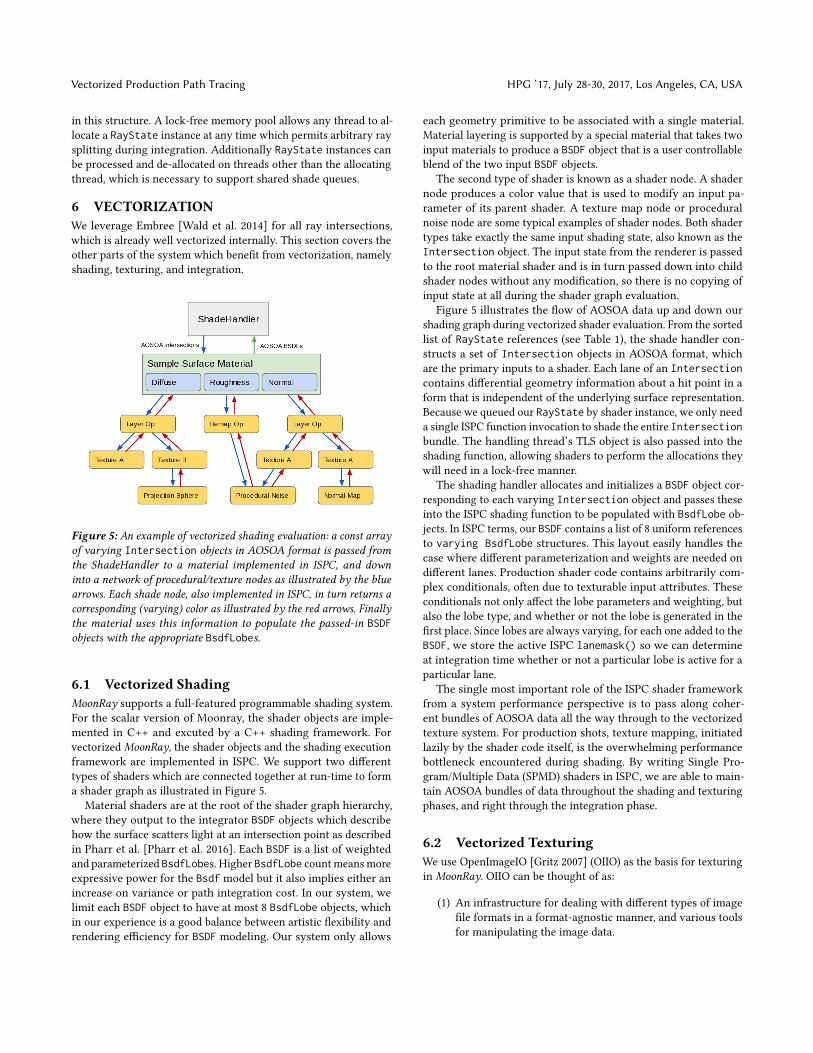
Figure 5: An example of vectorized shading evaluation: a const arrayof varying Intersection objects in AOSOA format is passed fromthe ShadeHandler to a material implemented in ISPC, and downinto a network of procedural/texture nodes as illustrated by the bluearrows. Each shade node, also implemented in ISPC, in turn returns acorresponding (varying) color as illustrated by the red arrows. Finallythe material uses this information to populate the passed-in BSDFobjects with the appropriate BsdfLobes.
6.1 Vectorized ShadingMoonRay supports a full-featured programmable shading system.For the scalar version of Moonray, the shader objects are imple-mented in C++ and excuted by a C++ shading framework. Forvectorized MoonRay, the shader objects and the shading executionframework are implemented in ISPC. We support two differenttypes of shaders which are connected together at run-time to forma shader graph as illustrated in Figure 5.
Material shaders are at the root of the shader graph hierarchy,where they output to the integrator BSDF objects which describehow the surface scatters light at an intersection point as describedin Pharr et al. [Pharr et al. 2016]. Each BSDF is a list of weightedand parameterized BsdfLobes. Higher BsdfLobe count means moreexpressive power for the Bsdf model but it also implies either anincrease on variance or path integration cost. In our system, welimit each BSDF object to have at most 8 BsdfLobe objects, whichin our experience is a good balance between artistic flexibility andrendering efficiency for BSDF modeling. Our system only allows
each geometry primitive to be associated with a single material.Material layering is supported by a special material that takes twoinput materials to produce a BSDF object that is a user controllableblend of the two input BSDF objects.
The second type of shader is known as a shader node. A shadernode produces a color value that is used to modify an input pa-rameter of its parent shader. A texture map node or proceduralnoise node are some typical examples of shader nodes. Both shadertypes take exactly the same input shading state, also known as theIntersection object. The input state from the renderer is passedto the root material shader and is in turn passed down into childshader nodes without any modification, so there is no copying ofinput state at all during the shader graph evaluation.
Figure 5 illustrates the flow of AOSOA data up and down ourshading graph during vectorized shader evaluation. From the sortedlist of RayState references (see Table 1), the shade handler con-structs a set of Intersection objects in AOSOA format, whichare the primary inputs to a shader. Each lane of an Intersectioncontains differential geometry information about a hit point in aform that is independent of the underlying surface representation.Because we queued our RayState by shader instance, we only needa single ISPC function invocation to shade the entire Intersectionbundle. The handling thread’s TLS object is also passed into theshading function, allowing shaders to perform the allocations theywill need in a lock-free manner.
The shading handler allocates and initializes a BSDF object cor-responding to each varying Intersection object and passes theseinto the ISPC shading function to be populated with BsdfLobe ob-jects. In ISPC terms, our BSDF contains a list of 8 uniform referencesto varying BsdfLobe structures. This layout easily handles thecase where different parameterization and weights are needed ondifferent lanes. Production shader code contains arbitrarily com-plex conditionals, often due to texturable input attributes. Theseconditionals not only affect the lobe parameters and weighting, butalso the lobe type, and whether or not the lobe is generated in thefirst place. Since lobes are always varying, for each one added to theBSDF, we store the active ISPC lanemask() so we can determineat integration time whether or not a particular lobe is active for aparticular lane.
The single most important role of the ISPC shader frameworkfrom a system performance perspective is to pass along coher-ent bundles of AOSOA data all the way through to the vectorizedtexture system. For production shots, texture mapping, initiatedlazily by the shader code itself, is the overwhelming performancebottleneck encountered during shading. By writing Single Pro-gram/Multiple Data (SPMD) shaders in ISPC, we are able to main-tain AOSOA bundles of data throughout the shading and texturingphases, and right through the integration phase.
6.2 Vectorized TexturingWe use OpenImageIO [Gritz 2007] (OIIO) as the basis for texturingin MoonRay. OIIO can be thought of as:
(1) An infrastructure for dealing with different types of imagefile formats in a format-agnostic manner, and various toolsfor manipulating the image data.

HPG ’17, July 28-30, 2017, Los Angeles, CA, USA Lee et al.
(2) A runtime image caching system which facilitates efficientrendering of scenes with larger texture memory footprintsthan could fit in physical memory.
(3) A runtime texture sampling system which layers on top ofthe image cache.
In our system, we make use of items 1 and 2 (with some cus-tomizations), but since all the inputs will already be in AOSOAformat as textures are sampled from within the vectorized shadingcode, this prompted us to implement a fully vectorized ISPC replace-ment for item 3. OIIO provides a virtual interface class for addingnew texture sampler implementations which simplified the process.We built upon the image tile cache functionality already provided inOIIO with the addition of a new set-associative micro-cache whichis described later.
One impactful decisionwe tookwas to switch to a point samplingfilter as our default. When sampling a texture, the appropriate adja-cent mip levels are first determined using texture derivatives. Onlya single non-interpolated value is looked up from each, and thesevalues themselves are linearly interpolated based on the derivatives.This means we only have to fetch two texels for each request, result-ing in a very fast, almost branchless texture lookup. Although wehave not done a rigorous quantitative analysis, it works out well inpractice. An informal justification for this decision can be thoughtof like so - we need to shoot sufficient primary rays to resolvegeometric aliasing, which can be considered of infinite frequency.Intuitively, this number of rays should also be sufficient to resolveany texture aliasing from the already band-limited mip levels wesample. We do however fall back to vectorized bilinear filteringwhen texture magnification is required, i.e. we don’t have a highenough resolution mip-map to satisfy the request.
OIIO has a main texture tile cache which is shared between allthreads, and a two element thread-local micro-cache layered ontop. This micro-cache was deemed too small to help much withvectorized execution since each vector lane may itself be accessinga different tile. To rectify this, we replaced it with a thread-local4-way set-associative cache [Handy 1998], configured to hold themost recent 256 tiles accessed. Tile eviction is done using a strictleast recently used policy. Moving up to 256 slots significantlyimproved the micro-cache hit rate over the default when runningvectorized code, particularly when many textures were bound toa shader. Although vectorized ISPC code generates the completelist of tiles for all lanes required to complete the operation, a C++function is called to query the micro-cache, and main tile cache ifrequired, in a sequential fashion.
Additional features we’ve implemented in the vectorized texturesamplers are full UDIM support, the option to return image mapderivatives (via finite differencing), and the ability to pre-load alltexture data in a scene during the preparation phase if desired.
6.3 Vectorized IntegrationThe ISPC integration kernel directly ingests batches of BSDF ob-jects in AOSOA format from the shaders. Recall from the previoussections, that each SOA BSDF is structurally identical on all SIMDlanes, however the parameters, weights, and dedicated lanemaskscan vary per lane, as each lane corresponds to a small set of coherentray hits using the same material shader and the same light-set.
Figure 6: This graph demonstrates how performance scales as thenumber of vector lanes increases. Although we still observe non-trivialgains when moving from 8 to 16 lanes, clearly we also see diminishingreturns. These numbers were captured by rendering the Bergen Townscene (Figure 2(a)) on Intel’s Knights Landing hardware.
The vectorized integrator can therefore proceed in a data-parallelfashion, drawing samples and performing all Bsdf and light impor-tance sampling, evaluation and MIS weighting calculcations inSIMD. Path splitting and Russian Roulette calculations are alsocomputed similarly. All this math-intensive body of code is writ-ten in ISPC, which automatically handles the lane masking withinits non-trivial control flow. As shown in Section 7, our vectorizedintegrator suffers from relatively little SIMD divergence.
A notable difficulty occurs with textured light importance sam-pling, which requires performing a binary search in conditionalcumulative distribution function tables that are different on eachlane. This causes memory gather and SIMD divergence of about50%.
To handle spawning new rays with or without path splitting, theintegrator fills arena allocated memory buffers with the requiredinformation to construct these new rays. The actual RayStateman-agement and subsequent queuing of spawned rays is handled witha call out to C++. In addition to the spawned rays, the integatorkernel is also responsible for providing a list of occlusion rays, anda list of radiances to add to the frame buffer (see the arrows whichemanate from the Shade Queue Handler in Figure 3(b)). Since theseoutputs are generated from ISPC, they will be in AOSOA format,so a conversion back to AOS format (see Section 5.3) is performedin C++ before the subsequent queuing of these items.
Rays from different generations are freely mixed within queuessince the majority of the shading/integration code paths are thesame regardless of depth. Since there isn’t any concept of a one-to-one correspondence between input and output rays, there isno risk of fragmentation and therefore no ray compaction norregeneration [Áfra et al. 2016] is required.
We put effort into ensuring that each lane executes completelyindependently of any other lane, since any cross communicationcould introduce unwanted indeterminism into the system whenrunning on multiple threads.

Vectorized Production Path Tracing HPG ’17, July 28-30, 2017, Los Angeles, CA, USA
Figure 7: Comparisons of scalar vs. vectorized execution time for the Poppy (Figure 1), Bergen Town, Astrid, and Hotspur (Figures 2(a), 2(b), 2(c))scenes respectively. The total time spent rendering corresponds to the height of each stack, measured in seconds. A legend on the right is providedto give a feel for how time is divided up between the various subsystems. A category called “Vectorization overhead” accounts for all the timespent in queuing, sorting, and AOSOA code. In general, the speedup we observe from vectorized execution is proportional to the percentage of timespent in shading, texturing and integration code.
Table 2: A breakdown of key statisics for the scenes profiled. The “ISPC time %” shows the percentage of time in our code we’re processing a vectorlane’s worth of samples simultaneously (e.g. 8 for AVX2). This is computed by taking the total time spent executing ISPC code and dividing it bythe total render time less any time spent inside of Embree. It’s interesting to note that Bergen Town shows a much higher percentage of timedevoted to vectorization overhead than other scenes. This can be attributed to it being one of the more simple scenes with basic geometry andshaders, and thus a higher ray throughput. The cost of queuing, sorting, and AOSOA tends to remain stable per ray and so the more complex theworkload, the more the vectorization overhead is amortized.
Scene Poppy BergenTown Astrid Hotspur
Total scalar time (mm:ss) 41:53 3:34 6:22 1:56Total vectorized time (mm:ss) 32:41 2:01 3:59 0:50Millions of rays/sec scalar 3.76 10.43 2.94 5.02Millions of rays/sec vectorized 4.75 18.47 5.01 11.57Millions of shader evals/sec scalar 1.66 5.43 1.73 1.14Millions of shader evals/sec vectorized 2.10 9.63 2.98 2.63Ray intersection subsystem speedup 1.02× 1.20× 1.00× 1.14×Shading subsystem speedup 5.09× 6.19× 4.54× 4.20×Texturing subsystem speedup 1.68× 4.24× 3.43× 2.90×Integration subsystem speedup 3.00× 2.75× 2.68× 2.72×Vectorization overhead % 6.86% 18.99% 7.48% 8.82%ISPC time % (excl. ray intersections) 58.57% 52.38% 70.47% 79.76%Light SIMD utilization % 61.77% 51.38% 68.72% 58.22%BSDF SIMD utilization % 71.96% 90.43% 70.39% 80.17%Overall speedup 1.28× 1.77× 1.60× 2.31×

HPG ’17, July 28-30, 2017, Los Angeles, CA, USA Lee et al.
7 RESULTSAll tests in Figure 7 were run on a machine with dual Intel XeonE5-2697 v3 CPUs running at 2.6GHz. Hyper-threading was disabledwhich gave a total of 28 hardware threads. We compiled the codeto target the AVX2 instruction set which is 8 lanes wide, and weconfigured the texture system to lazily load textures on demand.
Great care was taken to ensure we performed the same high levelcomputations in both scalar and vectorized modes, even though theinternal architecture and implementation can differ significantly.For example, since we wrote a custom texture sampler for thevectorized code path, we also implemented a scalar version withidentical functionality and outputs so that comparisons are fair.Each of the 4 images shown in Figures 1 and 2 is visually identicalwhen run in either mode. See Table 2 for associated statistics foreach scene profiled.
One important point to keep in mind when looking at the stackedgraphs in Figure 7 is that the blue and purple blocks represent timespent inside of Embree. Time spent inside Embree is outside of thescope of our optimization work in this paper, but can nonethelessbe a significant part of overall render time. In general we observelower overall speedup numbers for scenes where a lot of time isspent intersecting rays. This can be attributed to Embree being verywell optimized for both scalar and vectorized use cases.
A good example of this is in the Poppy scene (Figure 1). Everycharacter and asset in this scene is covered in hair or fuzz, resultingin the render time being very much dominated by ray/hair inter-sections [Woop et al. 2014]. In fact we spend 59% of time insideof Embree for the scalar case, a portion of time which doesn’t getfaster with vectorized execution. As a result we only have 41% ofthe frame time left to speed up. Despite this, we observe over a 2×speedup for all non-intersection related work, which results in a28% overall speedup when factoring in ray intersections.
The corollary to this however is that we observe larger speedupsin scenes which are dominated by shading, texturing and/or inte-gration. The remaining scenes show examples of this scenario.
Bergen Town (Figure 2(a)) is dominated by integration time (Fig-ure 7(b)), which as mentioned is a good case for the vectorized codepath. Interestingly, we do see a 20% speedup in ray intersectiontime here for vectorized execution, likely since this scene consistsof more typical pre-tesselated subdivision surfaces. This, combinedwith a 2.21× speedup in integration and a 4.24× speedup in textur-ing results in a 77% overall speedup compared to scalar mode. Thisscene was also profiled on Intel’s Knights Landing hardware usinglane widths of 4, 8, and 16; see Figure 6 for details.
Astrid (Figure 2(b)) is one of the main characters in the movie“How to Train Your Dragon”. She has long thick blond hair and herclothing is also covered in fur. Like the Poppy scene, we don’tsee a meaningful speedup between scalar and vectorized ray inter-sections in the Astrid render due to heavy hair intersection. Thenon-intersection related work however speeds up by a factor of2.45×, giving an overall speedup of 1.6× for the scene.
The Hotspur asset (Figure 2(c)) represents a typical environ-ment set piece in our films. Large environment elements have towithstand the challenge of being rendered close up from arbitrarycamera angles. They often rely on high resolution images which arelayered and projected via complex shader networks. In Hotspur’s
Figure 8: A plot of Embree ray intersection time vs. incoherent queuesize for the Bergen Town scene (Figure 2(a)). We tested using bothpacket and ray streaming APIs, and with and without ray sorting (thecost of ray sorting is not shown here). We observe only a relativelyslight speed up in ray intersection time. This, combined with the extratime required to sort rays, and additional memory usage to storeintermediate RayStates, ended up not being a win overall.
case there were over 6 layers of different blends and projectionswhich can access over 11 GB of texture data. In this type of setup,texturing is the primary bottleneck, followed by shading; see Fig-ure 7(d). In both of these vectorized code paths, we see large gains -a 3.44× speedup in shading and a 2.90× speedup in texturing, andan overall speedup of 2.31×.
Rendering cost grows logarithmically with geometric complexity,but linearly with shading and lighting complexity. Users typicallyadd many lights and layers of shaders and textures, which causesthe shading, texturing and path integration components of the ren-dering system to slow down proportionally. Fortunately, these arethe areas of our system that benefit the most from our vectorizationwork.
8 LIMITATIONSDuring development we experimented with ray sorting using anoptimized 5D sort in combination with ray queues up to 16 millionin size [Eisenacher et al. 2013]. Figure 8 shows the correspondingEmbree ray intersection performance. Consequently we are notcurrently pursuing this avenue. In our tests, the sweet spot for theincoherent ray queue size is about 1024 entries per thread. Whilstthis number itself is too small to manufacture any meaningful raycoherence from sorting, we do get some additional coherence as abyproduct of having a queue per shader instance, since each newbatch of ray hit and continuation rays will be correlated to surfaceswhich share that shader.
We don’t currently support lazy evaluation of procedurals forsimplicity of implementation, and due to the complex thread syn-chronization and potential contention when loading geometry as-sets while tracing paths through the scene. Instead, all proceduralsare expanded during the preparation phase, and we chose to placethe onus on the upstream pipeline or pre-processing tools to gener-ate appropriately trimmed scene files.

Vectorized Production Path Tracing HPG ’17, July 28-30, 2017, Los Angeles, CA, USA
Writing vectorized code and thinking in a vectorized fashioncan be a challenge in itself. It can be somewhat at odds with fastprototyping workflows required to keep a renderer fluidly evolving.A compromise we’ve found which has worked well so far is toallow execution of C++ scalar recursive code paths from within thevectorized framework. This allows programmers to experiment inthe same manner as they would in a scalar depth first context. Thisnew code runs at standard scalar speed since it’s not vectorized,but at the same time we still get the full benefit from the portionsof the code which are already vectorized. This hybrid approach hasbeen utilized to implement subsurface scattering and volumes. Asnew functionality solidifies over time, the slower scalar code canbe upgraded to full vectorized implementations.
9 CONCLUSIONWe presented a system-wide approach to vectorized path tracing.This included an efficient queueing and sorting foundation forextracting data and computation coherence; and vectorization ofthe remaining compute-intensive parts of path tracing: shading,texturing and integration.
In the introduction we asked the question “Do the potentialperformance benefits gained outweigh the extra work required toharness the vector hardware?”. In all scenes we profiled so far withMoonRay, the answer is a definitive yes.
We have seen that the actual speed up itself is very scene de-pendent. Scenes which spend the majority of time performing rayintersections benefit less than those which spend most of theirtime performing shading, texturing or integration computations.This is encouraging since we expect the relative shader and light-ing complexity to increase as more complex production scenes aredeveloped.
Results so far have been promising and we’re excited and opti-mistic to discover how MoonRay performs on its first full feature.
ACKNOWLEDGMENTSMoonRay is the work of two passionate teams of researchers andengineers, one working on the core renderer and the other onshaders and procedurals. This paper is dedicated to them! The au-thors would also like to express the most profound gratitude toour technology partners at Intel, and to the many open source con-tributors of Embree, ISPC, OpenImageIO and OpenSubdiv, withoutwhom this project could not have been realized. A special thankyou goes to Scott Cegielski, Conrad Egan, Krishna Mullia, and JonLanz for helping us with rendering tests, and to Pat Hanrahan andMatt Pharr, for providing feedback on in-progress drafts of thispaper.
REFERENCESMike Acton. 2014. Data-Oriented Design and C++. (2014). https://www.youtube.com/
watch?v=rX0ItVEVjHc.Attila T. Áfra, Carsten Benthin, Ingo Wald, and Jacob Munkberg. 2016. Local Shading
Coherence Extraction for SIMD-efficient Path Tracing on CPUs. In Proceedings ofHigh Performance Graphics (HPG ’16). 119–128.
Timo Aila and Tero Karras. 2010. Architecture Considerations for Tracing IncoherentRays. In Proceedings of the Conference on High Performance Graphics (HPG ’10).113–122.
Carsten Benthin, Ingo Wald, Sven Woop, Manfred Ernst, and William R. Mark. 2012.Combining Single and Packet-Ray Tracing for Arbitrary Ray Distributions on the
Intel MIC Architecture. IEEE Transactions on Visualization and Computer Graphics(2012), 1438–1448.
Robert L. Cook, Loren Carpenter, and Edwin Catmull. 1987. The Reyes Image RenderingArchitecture. In Proceedings of the 14th Annual Conference on Computer Graphicsand Interactive Techniques (SIGGRAPH ’87). 95–102.
Christian Eisenacher, Gregory Nichols, Andrew Selle, and Brent Burley. 2013. SortedDeferred Shading for Production Path Tracing. In Proceedings of the EurographicsSymposium on Rendering (EGSR ’13). 125–132.
Manfred Ernst and Gunther Greiner. 2008. Multi Bounding Volume Hierarchies. InIEEE Symposium on Interactive Ray Tracing (RT ’08).
Kirill Garanzha and Charles Loop. 2010. Fast Ray Sorting and Breadth-First PacketTraversal for GPU Ray Tracing. Computer Graphics Forum (2010), 289–298.
Larry Gritz. 2007. Open Image I/O. https://github.com/OpenImageIO/oiio/.Jim Handy. 1998. The Cache Memory Book. Morgan Kaufmann. https://www.elsevier.
com/books/cache-memory-book-the/handy/978-0-08-051878-7.P Hanrahan. 1986. Using Caching and Breadth-first Search to Speed Up Ray-tracing.
In Proceedings on Graphics Interface ’86/Vision Interface ’86. 56–61.Jared Hoberock, Victor Lu, Yuntao Jia, and John C. Hart. 2009. Stream Compaction for
Deferred Shading. In Proceedings of the Conference on High Performance Graphics2009 (HPG ’09). 173–180.
Sony Imageworks. 2017. Alembic. (2017). http://www.alembic.io/.Intel. 2010. Threading Building Blocks. https://www.threadingbuildingblocks.org/.Intel. 2011. Intel SPMD Program Compiler. https://ispc.github.io/.James T. Kajiya. 1986. The Rendering Equation. In Proceedings of the 13th Annual
Conference on Computer Graphics and Interactive Techniques (SIGGRAPH ’86). 143–150.
Alexander Keller, Carsten Wächter, Matthias Raab, Daniel Seibert, Dietger van Antwer-pen, Johann Korndörfer, and Lutz Kettner. 2017. The Iray Light Transport Simulationand Rendering System. CoRR abs/1705.01263 (2017). http://arxiv.org/abs/1705.01263
Janne Kontkanen, Eric Tabellion, and Ryan S. Overbeck. 2011. Coherent Out-of-corePoint-based Global Illumination. In Proceedings of the Twenty-second EurographicsConference on Rendering (EGSR ’11). 1353–1360.
Samuli Laine, Tero Karras, and Timo Aila. 2013. Megakernels Considered Harmful:Wavefront Path Tracing on GPUs. In Proceedings of the 5th High-PerformanceGraphics Conference (HPG ’13). 137–143.
Koji Nakamaru and Yoshio Ohno. 2002. Ray Tracing for Curve Primitives. In Proceedingsof Winter School of Computer Graphics (WSCG).
Jacopo Pantaleoni, Luca Fascione, Martin Hill, and Timo Aila. 2010. PantaRay: FastRay-traced Occlusion Caching of Massive Scenes. In ACM SIGGRAPH 2010 Papers(SIGGRAPH ’10). 37:1–37:10.
Steven G. Parker, James Bigler, Andreas Dietrich, Heiko Friedrich, Jared Hoberock,David Luebke, David McAllister, Morgan McGuire, Keith Morley, Austin Robison,and Martin Stich. 2010. OptiX: A General Purpose Ray Tracing Engine. In ACMSIGGRAPH 2010 Papers (SIGGRAPH ’10). 66:1–66:13.
Matt Pharr, Wenzel Jakob, and Greg Humphreys. 2016. Physically Based Rendering, 3rded. Morgan Kaufmann. http://www.pbrt.org/.
Matt Pharr, Craig Kolb, Reid Gershbein, and Pat Hanrahan. 1997. Rendering ComplexScenes with Memory-coherent Ray Tracing. In Proceedings of the 24th AnnualConference on Computer Graphics and Interactive Techniques (SIGGRAPH ’97). 101–108.
M. Pharr and W. R. Mark. 2012. ispc: A SPMD Compiler for High-Performance CPUProgramming. In 2012 Innovative Parallel Computing (InPar). 1–13.
Mike Seymour. 2014. UDIM UV mapping. (2014). https://www.fxguide.com/featured/udim-uv-mapping/.
John A. Tsakok. 2009. Faster Incoherent Rays: Multi-BVH Ray Stream Tracing. InProceedings of the Conference on High Performance Graphics 2009 (HPG ’09). 151–158.
Eric Veach and Leonidas J. Guibas. 1995. Optimally Combining Sampling Techniques forMonte Carlo Rendering. In Proceedings of the 22Nd Annual Conference on ComputerGraphics and Interactive Techniques (SIGGRAPH ’95). 419–428.
Jiří Vorba and Jaroslav Křivánek. 2016. Adjoint-Driven Russian Roulette and Splittingin Light Transport Simulation. ACM Trans. Graph. (2016), 1–11.
IngoWald. 2007. On Fast Construction of SAH-based Bounding Volume Hierarchies. InProceedings of the 2007 IEEE Symposium on Interactive Ray Tracing (RT ’07). 33–40.
IngoWald, Carsten Benthin, and Solomon Boulos. 2008. Getting rid of packets - EfficientSIMD single-ray traversal using multi-branching BVHs. In IEEE Symposium onInteractive Ray Tracing (RT ’08).
Ingo Wald, Sven Woop, Carsten Benthin, Gregory S. Johnson, and Manfred Ernst. 2014.Embree: A Kernel Framework for Efficient CPU Ray Tracing. ACM Trans. Graph.(2014), 143:1–143:8.
Sven Woop, Carsten Benthin, Ingo Wald, Gregory S. Johnson, and Eric Tabellion. 2014.Exploiting Local Orientation Similarity for Efficient Ray Traversal of Hair and Fur.In Proceedings of High Performance Graphics (HPG ’14). 41–49.