vega level-en
TRANSCRIPT

8/12/2019 vega level-EN
http://slidepdf.com/reader/full/vega-level-en 1/52
Operating Instructions
Ultrasonic sensor for continuous level
measurement
VEGASON 614 … 20 mA/HART - two-wire
Document ID: 28775

8/12/2019 vega level-EN
http://slidepdf.com/reader/full/vega-level-en 2/52
2
Contents
VEGASON 61 • 4 … 20 mA/HART - two-wire
2 8 7 7
5 -E N-1 3 0 4 1 7
Contents
1 About this document
1.1 Function ........................................................................................................................... 41.2 Target group ..................................................................................................................... 4
1.3 Symbolism used ...............................................................................................................42 For your safety
2.1 Authorised personnel ....................................................................................................... 5
2.2 Appropriate use ................................................................................................................ 5
2.3 Warning about incorrect use ............................................................................................. 5
2.4 General safety instructions ............................................................................................... 5
2.5 Safety label on the instrument .......................................................................................... 5
2.6 CE conformity ................................................................................................................... 5
2.7 Fulllment of NAMUR recommendations ......................................................................... 6
2.8 Safety instructions for Ex areas ........................................................................................ 6
2.9 Environmental instructions ............................................................................................... 6
3 Product description
3.1 Conguration .................................................................................................................... 7
3.2 Principle of operation........................................................................................................ 8
3.3 Operation ......................................................................................................................... 8
3.4 Packaging, transport and storage ..................................................................................... 9
4 Mounting
4.1 General instructions ....................................................................................................... 104.2 Mounting instructions ..................................................................................................... 11
5 Connecting to power supply5.1 Preparing the connection ............................................................................................... 17
5.2 Connection procedure .................................................................................................... 18
5.3 Wiring plan, single chamber housing.............................................................................. 19
5.4 Wiring plan, double chamber housing ............................................................................ 21
5.5 Wiring plan - version IP 66/IP 68 (1 bar) ......................................................................... 235.6 Switch-on phase.............................................................................................................23
6 Set up with the display and adjustment module PLICSCOM
6.1 Short description ............................................................................................................ 246.2 Insert display and adjustment module ............................................................................ 24
6.3 Adjustment system ......................................................................................................... 256.4 Setup steps .................................................................................................................... 26
6.5 Menu plan ultrasonic sensor .......................................................................................... 316.10 Saving the parameter adjustment data ........................................................................... 33
7 Set up with PACTware and other adjustment programs
7.1 Connect the PC via VEGACONNECT ............................................................................ 347.2 Parameter adjustment with PACTware............................................................................ 357.3 Parameter adjustment with AMS™ and PDM................................................................. 367.4 Saving the parameter adjustment data ........................................................................... 36
8 Maintenance and fault rectication
8.1 Maintenance .................................................................................................................. 378.2 Rectify faults ...................................................................................................................378.3 Exchanging the electronics module ................................................................................ 38

8/12/2019 vega level-EN
http://slidepdf.com/reader/full/vega-level-en 3/52
3
Contents
VEGASON 61 • 4 … 20 mA/HART - two-wire
2 8 7 7 5 - E N - 1 3 0 4 1 7
8.4 Software update ............................................................................................................. 388.5 Instrument repair ............................................................................................................ 39
9 Dismounting
9.1 Dismounting steps..........................................................................................................41
9.2 Disposal ......................................................................................................................... 4110 Supplement
10.1 Technical data ................................................................................................................ 4210.2 Dimensions .................................................................................................................... 47
Supplementary documentation
Information:Supplementary documents appropriate to the ordered version comewith the delivery. You can nd them listed in chapter "Product descrip-tion".
Instructions manuals for accessories and replacement parts
Tip:To ensure reliable setup and operation of your VEGASON 61, we oer
accessories and replacement parts. The corresponding documenta-tions are:
• 27835 - Display and adjustment module PLICSCOM
• 32628 - Interface adapter VEGACONNECT
• 27720 - External indication VEGADIS 61• 34296 - Protective cover
• 30176 - Electronics module VEGASON series 60
Editing status: 2013-04-11

8/12/2019 vega level-EN
http://slidepdf.com/reader/full/vega-level-en 4/52
4
1 About this document
VEGASON 61 • 4 … 20 mA/HART - two-wire
2 8 7 7
5 -E N-1 3 0 4 1 7
1 About this document
1.1 FunctionThis operating instructions manual provides all the information you
need for mounting, connection and setup as well as important instruc-tions for maintenance and fault rectication. Please read this informa-tion before putting the instrument into operation and keep this manualaccessible in the immediate vicinity of the device.
1.2 Target groupThis operating instructions manual is directed to trained specialistpersonnel. The contents of this manual should be made available tothese personnel and put into practice by them.
1.3 Symbolism usedInformation, tip, noteThis symbol indicates helpful additional information.
Caution: If this warning is ignored, faults or malfunctions can result.
Warning: If this warning is ignored, injury to persons and/or seriousdamage to the instrument can result.
Danger: If this warning is ignored, serious injury to persons and/ordestruction of the instrument can result.
Ex applications
This symbol indicates special instructions for Ex applications.• List
The dot set in front indicates a list with no implied sequence.
→ ActionThis arrow indicates a single action.
1 SequenceNumbers set in front indicate successive steps in a procedure.
Battery disposalThis symbol indicates special information about the disposal of bat-teries and accumulators.

8/12/2019 vega level-EN
http://slidepdf.com/reader/full/vega-level-en 5/52
5
2 For your safety
VEGASON 61 • 4 … 20 mA/HART - two-wire
2 8 7 7 5 - E N - 1 3 0 4 1 7
2 For your safety
2.1 Authorised personnelAll operations described in this operating instructions manual must
be carried out only by trained specialist personnel authorised by theplant operator.
During work on and with the device the required personal protectiveequipment must always be worn.
2.2 Appropriate useVEGASON 61 is a sensor for continuous level measurement.
You can nd detailed information on the application range in chapter"Product description".
Operational reliability is ensured only if the instrument is properlyused according to the specications in the operating instructionsmanual as well as possible supplementary instructions.
For safety and warranty reasons, any invasive work on the devicebeyond that described in the operating instructions manual may becarried out only by personnel authorised by the manufacturer. Arbi-trary conversions or modications are explicitly forbidden.
2.3 Warning about incorrect useInappropriate or incorrect use of the instrument can give rise toapplication-specic hazards, e.g. vessel overll or damage to system
components through incorrect mounting or adjustment.
2.4 General safety instructionsThis is a high-tech instrument requiring the strict observance of stand-ard regulations and guidelines. The user must take note of the safetyinstructions in this operating instructions manual, the country-specic
installation standards as well as all prevailing safety regulations andaccident prevention rules.
The instrument must only be operated in a technically awless and
reliable condition. The operator is responsible for trouble-free opera-
tion of the instrument.During the entire duration of use, the user is obliged to determine thecompliance of the necessary occupational safety measures with thecurrent valid rules and regulations and also take note of new regula-tions.
2.5 Safety label on the instrumentThe safety approval markings and safety tips on the device must beobserved.
2.6 CE conformityThis device fullls the legal requirements of the applicable EC guide-lines. By attaching the CE mark, VEGA provides a conrmation of
8/12/2019 vega level-EN
http://slidepdf.com/reader/full/vega-level-en 6/52
6
2 For your safety
VEGASON 61 • 4 … 20 mA/HART - two-wire
2 8 7 7
5 -E N-1 3 0 4 1 7
successful testing. You can nd the CE conformity declaration in thedownload area of "www.vega.com".
2.7 Fulllment of NAMUR recommendations
NAMUR is the automation technology user association in the processindustry in Germany. The published NAMUR recommendations areaccepted as the standard in eld instrumentation.
The device fullls the requirements of the following NAMUR recom-mendations:
• NE 21 – Electromagnetic compatibility of equipment
• NE 43 – Signal level for malfunction information from measuringtransducers
• NE 53 – Compatibility of eld devices and display/adjustmentcomponents
For further information see www.namur.de.
2.8 Safety instructions for Ex areasPlease note the Ex-specic safety information for installation and op-eration in Ex areas. These safety instructions are part of the operatinginstructions manual and come with the Ex-approved instruments.
2.9 Environmental instructionsProtection of the environment is one of our most important duties.That is why we have introduced an environment management system
with the goal of continuously improving company environmental pro-tection. The environment management system is certied accordingto DIN EN ISO 14001.
Please help us fulll this obligation by observing the environmental
instructions in this manual:
• Chapter "Packaging, transport and storage"
• Chapter "Disposal "
8/12/2019 vega level-EN
http://slidepdf.com/reader/full/vega-level-en 7/52
7
3 Product description
VEGASON 61 • 4 … 20 mA/HART - two-wire
2 8 7 7 5 - E N - 1 3 0 4 1 7
3 Product description
3.1 Conguration
The scope of delivery encompasses:
• VEGASON 61 ultrasonic sensor• Documentation – this operating instructions manual – Safety Manual 28983 "VEGASON 61, 62 - 4 … 20 mA/HART "
(optional) – Operating instructions manual 27835 "Display and adjustment
module PLICSCOM " (optional) – Supplementary instructions manual 31708 "Heating for display
and adjustment module PLICSCOM " (optional) – Supplementary instructions manual "Plug connector for con-
tinuously measuring sensors" (optional)
– Ex-specic "Safety instructions" (with Ex versions) – if necessary, further certicates
1
2
3
Fig. 1: VEGASON 61 - version with plastic housing
1 Housing cover with integrated PLICSCOM (optional)
2 Housing with electronics, optionally available with plug connector 3 Process ftting with transducer
The VEGASON 61 consists of the components:
• Transducer with integrated temperature sensor
• Housing with electronics, optionally available with plug connector
• Housing cover, optionally available with display and adjustmentmodule PLICSCOM
The components are available in dierent versions.
The nameplate contains the most important data for identication and
use of the instrument:
• Instrument version
• Article and serial number device
Scope of delivery
Constituent parts
Type plate

8/12/2019 vega level-EN
http://slidepdf.com/reader/full/vega-level-en 8/52
8
3 Product description
VEGASON 61 • 4 … 20 mA/HART - two-wire
2 8 7 7
5 -E N-1 3 0 4 1 7
• Article numbers, documentation
• Technical data: For example approvals, process temperature,process tting/material, signal output, power supply, protection
• SIL identication (with SIL rating ex works)
With the serial number, you can access the delivery data of the instru-ment via www.vega.com, "VEGA Tools" and "serial number search".In addition to the type label outside, you can also nd the serial num-ber on the inside of the instrument.
3.2 Principle of operationVEGASON 61 is an ultrasonic sensor for continuous level measure-ment. It is suitable for liquids and solids in virtually all industries,particularly in the water and waste water industry.
The transducer of the ultrasonic sensor transmits short ultrasonic
pulses to the measured product. These pulses are reected byproduct surface and received back by the transducer as echoes.The running time of the ultrasonic pulses from emission to receptionis proportional to the distance and hence the level. The determinedlevel is converted into an appropriate output signal and outputted asmeasured value.
4 … 20 mA/HART two-wire electronics for voltage supply and meas-ured value transmission on the same cable.
The supply voltage range can dier depending on the instrument
version.
The data for power supply are specied in chapter "Technical data".
The optional background lighting of the display and adjustmentmodule is powered by the sensor. A certain level of operating voltageis required for this. You can nd the exact voltage specications inchapter "Technical data".
The optional heating requires its own operating voltage. You can nddetails in the supplementary instructions manual "Heating for displayand adjustment module".
This function is generally not available for approved instruments.
3.3 OperationThe instrument can be adjusted with the following adjustment media:
• With the display and adjustment module
• with the suitable VEGA DTM in conjunction with an adjustmentsoftware according to the FDT/DTM standard, e.g. PACTware andPC
• with manufacturer-specic adjustment programs AMS™ or PDM
• With a HART handheld
Application area
Functional principle
Voltage supply

8/12/2019 vega level-EN
http://slidepdf.com/reader/full/vega-level-en 9/52
9
3 Product description
VEGASON 61 • 4 … 20 mA/HART - two-wire
2 8 7 7 5 - E N - 1 3 0 4 1 7
3.4 Packaging, transport and storageYour instrument was protected by packaging during transport. Itscapacity to handle normal loads during transport is assured by a testbased on ISO 4180.
The packaging of standard instruments consists of environment-friendly, recyclable cardboard. For special versions, PE foam or PEfoil is also used. Dispose of the packaging material via specialisedrecycling companies.
Transport must be carried out under consideration of the notes on thetransport packaging. Nonobservance of these instructions can causedamage to the device.
The delivery must be checked for completeness and possible transitdamage immediately at receipt. Ascertained transit damage or con-
cealed defects must be appropriately dealt with.
Up to the time of installation, the packages must be left closed andstored according to the orientation and storage markings on theoutside.
Unless otherwise indicated, the packages must be stored only underthe following conditions:
• Not in the open
• Dry and dust free
• Not exposed to corrosive media
• Protected against solar radiation
• Avoiding mechanical shock and vibration
• Storage and transport temperature see chapter "Supplement -Technical data - Ambient conditions"
• Relative humidity 20 … 85 %
Packaging
Transport
Transport inspection
Storage
Storage and transporttemperature

8/12/2019 vega level-EN
http://slidepdf.com/reader/full/vega-level-en 10/52
10
4 Mounting
VEGASON 61 • 4 … 20 mA/HART - two-wire
2 8 7 7
5 -E N-1 3 0 4 1 7
4 Mounting
4.1 General instructionsMake sure that all parts of the instrument coming in direct contact
with the process, especially the sensor element, process seal andprocess tting, are suitable for the existing process conditions, such
as process pressure, process temperature as well as the chemicalproperties of the medium.
You can nd the specications in chapter "Technical data" and on the
nameplate.
Select an installation position you can easily reach for mounting andconnecting as well as later retrotting of a display and adjustmentmodule. The housing can be rotated by 330° without the use of anytools. You can also install the display and adjustment module in four
dierent positions (each displaced by 90°).
Use the recommended cables (see chapter "Connecting to powersupply ") and tighten the cable gland.
You can give your instrument additional protection against moisturepenetration by leading the connection cable downward in front of thecable entry. Rain and condensation water can thus drain o. This ap-plies mainly to outdoor mounting as well as installation in areas wherehigh humidity is expected (e.g. through cleaning processes) or oncooled or heated vessels.
Fig. 2: Measures against moisture penetration
The reference plane for the measuring range is the lower edge of thetransducer.
Make sure that a minimum distance from the reference plane - the
so-called dead band, in which measurement is not possible - ismaintained. The exact value of the dead band is stated in chapter"Technical data".
Suitability for the processconditions
Installation position
Moisture
Measuring range

8/12/2019 vega level-EN
http://slidepdf.com/reader/full/vega-level-en 11/52
11
4 Mounting
VEGASON 61 • 4 … 20 mA/HART - two-wire
2 8 7 7 5 - E N - 1 3 0 4 1 7
1
2
Fig. 3: Minimum distance to the max. level
1 Dead band 2 Reference plane
Information:If the medium reaches the transducer, buildup can form on it andcause faulty measurements later on.
1 32
100%
0%
Fig. 4: Measuring range (operating range) and max. measuring distance
1 full 2 empty (max. measuring distance)3 Measuring range
Gauge pressure in the vessel does not inuence VEGASON 61. Lowpressure or vacuum does, however, damp the ultrasonic pulses. Thisinuences the measuring result, particularly if the level is very low.With pressures under -0.2 bar (-20 kPa) you should use a dierent
measuring principle, e.g. radar or guided microwave.
4.2 Mounting instructionsScrew VEGASON 61 into the mounting socket with an appropriatespanner applied to the hexagon of the process tting. Max. torque seechapter "Technical data".
Warning:The housing must not be used to screw the instrument in! Applyingtightening force can damage internal parts of the housing.
Pressure/Vacuum
Screwing in
8/12/2019 vega level-EN
http://slidepdf.com/reader/full/vega-level-en 12/52
12
4 Mounting
VEGASON 61 • 4 … 20 mA/HART - two-wire
2 8 7 7
5 -E N-1 3 0 4 1 7
When mounting the sensor, keep a distance of at least 200 mm(7.874 in) to the vessel wall. If the sensor is installed in the center ofdished or round vessel tops, multiple echoes can arise. These can,however, be suppressed by an appropriate adjustment (see chapter"Setup").
1
2
> 200 mm
Fig. 5: Mounting on round vessel tops
1 Reference plane 2 Vessel center or symmetry axis
If you cannot keep this distance you should carry out a false echostorage before setup. This applies mainly if buildup on the vessel wallis expected. In this case, we recommend repeating a false echo stor-
age later with existing buildup.In vessels with conical bottom it can be advantageous to mount thesensor in the center of the vessel, as measurement is then possibledown to the lowest point of the vessel bottom.
Fig. 6: Vessel with conical bottom
Socket pieces should be dimensioned so that the lower end of thetransducer protrudes at least 10 mm (0.394 in) out of the socket.
Installation position
Socket

8/12/2019 vega level-EN
http://slidepdf.com/reader/full/vega-level-en 13/52
13
4 Mounting
VEGASON 61 • 4 … 20 mA/HART - two-wire
2 8 7 7 5 - E N - 1 3 0 4 1 7
c a .
1 0
m m
Fig. 7: Recommended socket mounting
If the reective properties of the medium are good, you can mount
VEGASON 61 on sockets which are higher than the length of thetransducer. You will nd recommended values for socket heights in the
following illustration. The socket end should be smooth and burr-free,if possible also rounded. Carry out a false echo storage.
h
d h
80 mm/3"
100 mm/4"
150 mm/6"
150 mm/6"
300 mm/12"
400 mm/16"
d
Fig. 8: Deviating socket dimensions
Align the sensor in liquids as vertical as possible to the product sur-face to achieve an optimum measurement result.
Fig. 9: Alignment in liquids
To reduce the min. distance to the medium, you can also mount VE-GASON 61 with a beam deector. By doing this, it is possible to ll the
vessel nearly to maximum. Such an arrangement is suitable primarilyfor open vessels such as e.g. overow basins.
Sensor orientation

8/12/2019 vega level-EN
http://slidepdf.com/reader/full/vega-level-en 14/52
14
4 Mounting
VEGASON 61 • 4 … 20 mA/HART - two-wire
2 8 7 7
5 -E N-1 3 0 4 1 7
~200
~ 4 0 0 x 4
0 0
4 5 °
Fig. 10: Beam deector
The ultrasonic sensor should be installed at a location where noinstallations cross the ultrasonic beam.
Vessel installations such as for example, ladders, limit switches, heat-ing spirals, struts etc. can cause false echoes that interfere with theuseful echo. Make sure when planning your measuring site that the
ultrasonic signals have a "clear view" to the measured product.In case of existing vessel installations, a false echo storage should becarried out during setup.
If large vessel installations such as struts or supports cause falseechoes, these can be attenuated through supplementary measures.Small, inclined sheet metal or plastic baes above the installationsscatter the ultrasonic signals and avoid direct false echoes.
α
α
α
α
α
α
Fig. 11: Cover smooth profles with deectors
If there are agitators in the vessel, a false signal memory should becarried out with the agitators in motion. This ensures that the interfer-ing reections from the agitators are saved with the blades in dierent
positions.
Vessel installations
Agitators

8/12/2019 vega level-EN
http://slidepdf.com/reader/full/vega-level-en 15/52
15
4 Mounting
VEGASON 61 • 4 … 20 mA/HART - two-wire
2 8 7 7 5 - E N - 1 3 0 4 1 7
Fig. 12: Agitators
Do not mount the instruments in or above the lling stream. Make surethat you detect the product surface, not the inowing product.
Fig. 13: Inowing liquid
Through the action of lling, stirring and other processes in the vessel,dense foams which considerably damp the emitted signals may formon the product surface.
If foams are causing measurement errors, the sensor should be usedin a standpipe or, alternatively, the more suitable guided radar sen-sors (TDR) should be used.
Guided wave radar is unaected by foam generation and is particu-larly suitable for such applications.
If there are strong air currents in the vessel, e.g. due to strong windsin outdoor installations or air turbulence, e.g. by cyclone extractionyou should mount VEGASON 61 in a standpipe or use a dierentmeasuring principle, e.g. radar or guided radar (TDR).
Inowing medium
Foam
Air turbulences

8/12/2019 vega level-EN
http://slidepdf.com/reader/full/vega-level-en 16/52
16
4 Mounting
VEGASON 61 • 4 … 20 mA/HART - two-wire
2 8 7 7
5 -E N-1 3 0 4 1 7
By using a standpipe (surge or bypass tube), the inuence of vesselinstallations, foam generation and turbulence is excluded.
Standpipes must extend all the way down to the requested min. level,as measurement is only possible within the tube.
max.
min.
1
Fig. 14: Standpipe in the tank
1 Vent hole: ø 5 … 10 mm (0.197 … 0.394 in)
VEGASON 61 can be used from tube diameters of 40 mm (1.575 in).
Avoid large gaps and thick welding joints when connecting the tubes.Generally carry out a false echo storage.
Measurement in a standpipe is not recommended for extremely
adhesive products.
Standpipe measurement

8/12/2019 vega level-EN
http://slidepdf.com/reader/full/vega-level-en 17/52
17
5 Connecting to power supply
VEGASON 61 • 4 … 20 mA/HART - two-wire
2 8 7 7 5 - E N - 1 3 0 4 1 7
5 Connecting to power supply
5.1 Preparing the connectionAlways keep in mind the following safety instructions:
• Connect only in the complete absence of line voltage• If overvoltage surges are expected, overvoltage arresters shouldbe installed
Tip:We recommend using VEGA overvoltage arresters B63-48 andÜSB 62-36G.X.
In hazardous areas you must take note of the respective regulations,conformity and type approval certicates of the sensors and powersupply units.
Power supply and current signal are carried on the same two-wirecable. The voltage supply range can dier depending on the instru-ment version.
The data for power supply are specied in chapter "Technical data".
Provide a reliable separation between the supply circuit and themains circuits according to DIN EN 61140 VDE 0140-1. The VEGApower supply units VEGATRENN 149A Ex, VEGASTAB 690 as wellas all VEGAMETs and VEGASCANs meet this requirement.
Keep in mind the following additional factors that inuence the operat-ing voltage:
• Output voltage of the power supply unit can be lower under nomi-nal load (with a sensor current of 20.5 mA or 22 mA in case of faultmessage)
• Inuence of additional instruments in the circuit (see load values inchapter "Technical data")
The instrument is connected with standard two-wire cable withoutscreen. If electromagnetic interference is expected which is above thetest values of EN 61326 for industrial areas, screened cable shouldbe used.
Use cable with round cross-section. A cable outer diameter of5 … 9 mm (0.2 … 0.35 in) ensures the seal eect of the cable gland.
If you are using cable with a dierent diameter or cross-section,exchange the seal or use a suitable cable gland.
We generally recommend the use of screened cable for HART multi-drop mode.
On the instrument with cable entry ½ NPT and plastic housing there isa metallic ½" threaded insert moulded into the plastic housing.
Caution:
No grease should be used when screwing the NPT cable gland orsteel tube into the threaded insert. Standard grease can containadditives that corrode the connection between threaded insert and
Safety instructions
Voltage supply
Connection cable
Cable gland ½ NPT

8/12/2019 vega level-EN
http://slidepdf.com/reader/full/vega-level-en 18/52
18
5 Connecting to power supply
VEGASON 61 • 4 … 20 mA/HART - two-wire
2 8 7 7
5 -E N-1 3 0 4 1 7
housing. This would inuence the stability of the connection and thetightness of the housing.
If screened cable is necessary, connect the cable screen on bothends to ground potential. In the sensor, the screen must be connected
directly to the internal ground terminal. The ground terminal on theoutside of the housing must be connected to the potential equalisa-tion (low impedance).
If potential equalisation currents are expected, the connection on theprocessing side must be made via a ceramic capacitor (e. g. 1 nF,1500 V). The low-frequency potential equalisation currents are thussuppressed, but the protective eect against high frequency interfer-ence signals remains.
Warning:Considerable potential dierences exist inside galvanic plants as well
as vessels with cathodic corrosion protection. Very large equalisa-tion currents can ow through the cable screen when the screenis grounded on both ends. To avoid this, the cable screen must beconnected to ground potential only on one end (inside the switch-ing cabinet) in such applications. The cable screen must not beconnected to the internal ground terminal in the sensor and the outerground terminal on the housing not to potential equalisation!
Information:The metallic parts of the instrument (transmitter, process tting, etc.)are conductively connected with the inner and outer ground terminalon the housing. This connection exists either as a direct metalliccontact or via the shielding of the special connection cable on instru-ments with external electronics. You can nd specications on the po-tential connections within the instrument in chapter "Technical data".
Take note of the corresponding installation regulations for Ex applica-tions. In particular, make sure that no potential equalisation currentsow over the cable screen. In case of grounding on both sides this
can be achieved by the use of a capacitor or a separate potentialequalisation.
5.2 Connection procedureProceed as follows:
1. Unscrew the housing cover
2. If a display and adjustment module is installed, remove it by turn-ing it to the left.
3. Loosen compression nut of the cable entry
4. Remove approx. 10 cm (4 in) of the cable mantle, strip approx.1 cm (0.4 in) of insulation from the ends of the individual wires
5. Insert the cable into the sensor through the cable entry
6. Lift the opening levers of the terminals with a screwdriver (seefollowing illustration)
7. Insert the wire ends into the open terminals according to the wir-ing plan
Cable screening andgrounding

8/12/2019 vega level-EN
http://slidepdf.com/reader/full/vega-level-en 19/52
19
5 Connecting to power supply
VEGASON 61 • 4 … 20 mA/HART - two-wire
2 8 7 7 5 - E N - 1 3 0 4 1 7
Fig. 15: Connection steps 6 and 7
8. Press down the opening levers of the terminals, you will hear theterminal spring closing
9. Check the hold of the wires in the terminals by lightly pulling onthem
10. Connect the screen to the internal ground terminal, connect theouter ground terminal to potential equalisation
11. Tighten the compression nut of the cable entry. The seal ring mustcompletely encircle the cable
12. Screw the housing cover back on
The electrical connection is hence nished.
5.3 Wiring plan, single chamber housingThe following illustrations apply to the non-Ex as well as to the Ex-iaversion.

8/12/2019 vega level-EN
http://slidepdf.com/reader/full/vega-level-en 20/52
20
5 Connecting to power supply
VEGASON 61 • 4 … 20 mA/HART - two-wire
2 8 7 7
5 -E N-1 3 0 4 1 7
5
5
5 5
1 2
4
3
Fig. 16: Material versions, single chamber housing
1 Plastic 2 Aluminium3 Stainless steel, investment casting4 Stainless steel, electro-polished 5 Filter element for air pressure compensation of all material versions. Blind
plug with version IP 66/IP 68, 1 bar for Aluminium and stainless steel
I²C
Display
1 2 5 6 7 8
3
4
1
2
Fig. 17: Electronics and connection compartment, single chamber housing
1 Plug connector for VEGACONNECT (I²C interface) 2 Spring-loaded terminals for connection of the external indication VEGADIS
613 Ground terminal for connection of the cable screen4 Spring-loaded terminals for voltage supply
Housing overview
Electronics and connec-tion compartment

8/12/2019 vega level-EN
http://slidepdf.com/reader/full/vega-level-en 21/52
21
5 Connecting to power supply
VEGASON 61 • 4 … 20 mA/HART - two-wire
2 8 7 7 5 - E N - 1 3 0 4 1 7
I2C
Display
1
1 2 5 6 7 8
Fig. 18: Wiring plan, single chamber housing
1 Voltage supply, signal output
5.4 Wiring plan, double chamber housing
The following illustrations apply to the non-Ex as well as to the Ex-iaversion.
1 2 3
4 5
Fig. 19: Double chamber housing1 Housing cover, connection compartment 2 Blind plug or plug M12 x 1 for VEGADIS 61 (optional)3 Housing cover, electronics compartment 4 Filter element for air pressure compensation5 Cable gland
Wiring plan
Housing overview

8/12/2019 vega level-EN
http://slidepdf.com/reader/full/vega-level-en 22/52
22
5 Connecting to power supply
VEGASON 61 • 4 … 20 mA/HART - two-wire
2 8 7 7
5 -E N-1 3 0 4 1 7
1
3 2
Display
1 2 5 6 7 8
I2C
Fig. 20: Electronics compartment, double chamber housing
1 Plug connector for VEGACONNECT (I²C interface) 2 Internal connection cable to the connection compartment 3 Terminals for VEGADIS 61
1
2
3
D i s p l a y
1 2 I2C
Fig. 21: Connection compartment, double chamber housing
1 Spring-loaded terminals for voltage supply 2 Plug connector for VEGACONNECT (I²C interface)3 Ground terminal for connection of the cable screen
Electronics compartment
Connection compartment

8/12/2019 vega level-EN
http://slidepdf.com/reader/full/vega-level-en 23/52
23
5 Connecting to power supply
VEGASON 61 • 4 … 20 mA/HART - two-wire
2 8 7 7 5 - E N - 1 3 0 4 1 7
I2C
1
1 2
Fig. 22: Wiring plan, double chamber housing
1 Voltage supply, signal output
5.5 Wiring plan - version IP 66/IP 68 (1 bar)
1
2
Fig. 23: Wire assignment, connection cable
1 brown (+) and blue (-) to power supply or to the processing system 2 Shielding
5.6 Switch-on phaseAfter connecting VEGASON 61 to power supply or after a voltagerecurrence, the instrument carries out a self-check for approx. 30seconds:
• Internal check of the electronics
• Indication of the instrument type, the rmware as well as the sen-sor TAGs (sensor designation)
• Output signal jumps briey (approx. 10 seconds) to the set faultcurrent
Then the corresponding current is outputted to the cable (the valuecorresponds to the actual level as well as the settings already carriedout, e.g. factory setting).
Wiring plan
Wire assignment, con-nection cable
Switch-on phase

8/12/2019 vega level-EN
http://slidepdf.com/reader/full/vega-level-en 24/52
24
6 Set up with the display and adjustment module PLICSCOM
VEGASON 61 • 4 … 20 mA/HART - two-wire
2 8 7 7
5 -E N-1 3 0 4 1 7
6 Set up with the display and adjustmentmodule PLICSCOM
6.1 Short description
The display and adjustment module is used for measured valuedisplay, adjustment and diagnosis. It can be mounted in the followinghousing versions and instruments:
• All sensors of the plics® instrument family, in the single as well asin the double chamber housing (optionally in the electronics orconnection compartment)
• External display and adjustment unit VEGADIS 61
With hardware version …- 01 or higher of PLICSCOM or …- 02, …-04or higher of the respective sensor, an integrated backlight can beswitched on via the adjustment menu. The hardware version is stated
on the type label of the PLICSCOM or the sensor electronics.
Note:You can nd detailed information on the adjustment in the operatinginstructions manual "Display and adjustment module".
6.2 Insert display and adjustment moduleThe display and adjustment module can be inserted into the sensorand removed again at any time. It is not necessary to interrupt thepower supply.
Proceed as follows:
1. Unscrew the housing cover
2. Place the display and adjustment module in the desired positionon the electronics (you can choose any one of four dierent posi-tions - each displaced by 90°)
3. Press the display and adjustment module onto the electronicsand turn it to the right until it snaps in.
4. Screw housing cover with inspection window tightly back on
Removal is carried out in reverse order.
The display and adjustment module is powered by the sensor, an ad-ditional connection is not necessary.
Function/Conguration
Mount/Dismount displayand adjustment module

8/12/2019 vega level-EN
http://slidepdf.com/reader/full/vega-level-en 25/52
25
6 Set up with the display and adjustment module PLICSCOM
VEGASON 61 • 4 … 20 mA/HART - two-wire
2 8 7 7 5 - E N - 1 3 0 4 1 7
Fig. 24: Insert display and adjustment module
Note:If you intend to retrot the instrument with a display and adjustment
module for continuous measured value indication, a higher cover withan inspection glass is required.
6.3 Adjustment system
2
3
1
1.1
Fig. 25: Display and adjustment elements
1 LC display 2 Indication of the menu item number 3 Adjustment keys
• [OK] key: – Move to the menu overview – Conrm selected menu – Edit parameter
Key functions

8/12/2019 vega level-EN
http://slidepdf.com/reader/full/vega-level-en 26/52
26
6 Set up with the display and adjustment module PLICSCOM
VEGASON 61 • 4 … 20 mA/HART - two-wire
2 8 7 7
5 -E N-1 3 0 4 1 7
– Save value
• [->] key to select: – Menu change – Select list entry – Select editing position
• [+] key: – Change value of the parameter
• [ESC] key: – interrupt input – Jump to next higher menu
The sensor is adjusted via the four keys of the display and adjust-ment module. The LC display indicates the individual menu items. Thefunctions of the individual keys are shown in the above illustration.
Approx. 10 minutes after the last pressing of a key, an automatic resetto measured value indication is triggered. Any values not conrmed
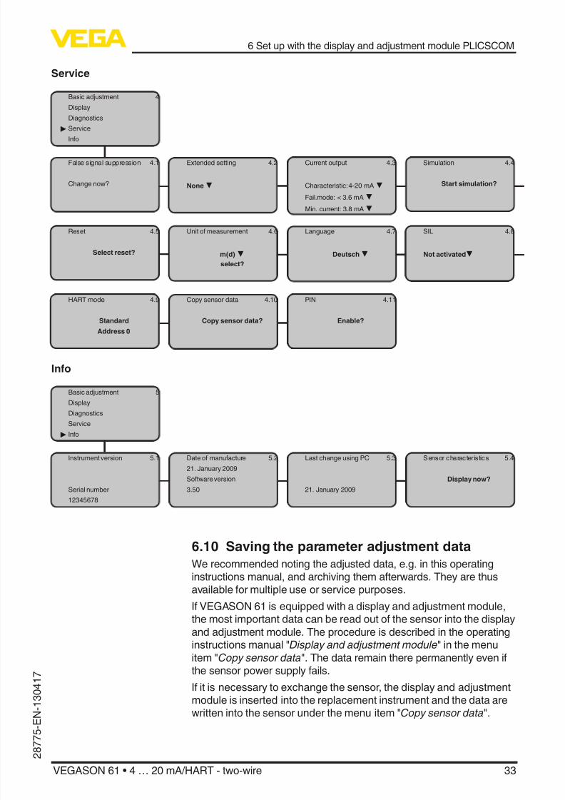
with [OK] will not be saved.
6.4 Setup stepsIn HART-Multidrop mode (several sensors on one input) the addressmust be set before continuing with the parameter adjustment. Youwill nd a detailed description in the operating instructions manual"Display and adjustment module" or in the online help of PACTware
or DTM.
HART mode
Standard
Address 0
As VEGASON 61 is a distance measuring instrument, the distancefrom the sensor to the product surface is measured. To have the realproduct level displayed, an allocation of the measured distance to thepercentage height must be made. To carry out this adjustment, thedistance is entered with full and empty vessel. If these values are not
known, an adjustment with the distance values, e.g. 10 % and 90 %is also possible. Starting point for these distance specications isalways the lower side of the ange, with all other versions the lowerside of the transducer.
The actual level is then calculated on the basis of these enteredvalues. At the same time, the operating range of the sensor is limitedfrom maximum range to the requested range.
The real product level during this adjustment is not important, be-cause the min./max. adjustment is always carried out without chang-ing the product level. These settings can be made ahead of timewithout the instrument having to be installed.
In the main menu item "Basic adjustment ", the individual submenu
items should be selected one after the other and provided with thecorrect parameter values.
Adjustment system
Address setting HARTmultidrop
Parameter adjustment

8/12/2019 vega level-EN
http://slidepdf.com/reader/full/vega-level-en 27/52
27
6 Set up with the display and adjustment module PLICSCOM
VEGASON 61 • 4 … 20 mA/HART - two-wire
2 8 7 7 5 - E N - 1 3 0 4 1 7
Start your parameter adjustment with the following menu items of thebasic adjustment:
Proceed as follows:
1. Move from the measured value display to the main menu by
pushing [OK] . Basic adjustment
Display
Diagnostics
Service
Info
2. Select the menu item "Basic adjustment " with [->] and conrm
with [OK] . Now the menu item "Min. adjustment " is displayed.
Min. adjustment
0.00 %
=
5.000 m(d)
4.000 m(d)
3. Prepare the % value for editing with [OK] and set the cursor to therequested position with [->] . Set the requested percentage valuewith [+] and save with [OK] . The cursor jumps now to the distancevalue.
4. Enter the suitable distance value in m for the empty vessel (e.g.distance from the sensor to the vessel bottom) corresponding tothe percentage value.
5. Save the settings with [OK] and move to "Max. adjustment" with
[->] .
Proceed as follows:
Max. adjustment
100.00 %
=
1.000 m(d)
2.000 m(d)
1. Prepare the % value for editing with [OK] and set the cursor to therequested position with [->] . Set the requested percentage valuewith [+] and save with [OK] . The cursor jumps now to the distancevalue.
2. Enter the appropriate distance value in m (corresponding to thepercentage value) for the full vessel. Keep in mind that the max.level must lie below the dead band.
3. Save the settings with [OK] and move to "Medium selection" with [->] .
Each product has dierent reective properties. In addition, thereare various interfering factors which have to be taken into account:agitated product surfaces and foam generation (with liquids); dust
generation, material cones and echoes from the vessel wall (withsolids). To adapt the sensor to these dierent conditions, you should
rst select "Liquid " or "Solid ".
Carry out min. adjustment
Carry out max. adjust-ment
Medium selection

8/12/2019 vega level-EN
http://slidepdf.com/reader/full/vega-level-en 28/52
28
6 Set up with the display and adjustment module PLICSCOM
VEGASON 61 • 4 … 20 mA/HART - two-wire
2 8 7 7
5 -E N-1 3 0 4 1 7
Medium
Liquid
With solids, you can also choose between "Powder/Dust ", "Granular/ Pellets" or "Ballast/Pebbels".
Through this additional selection, the sensor is adapted perfectly tothe product and measurement reliability, particularly in products withpoor reective properties, is considerably increased.
Enter the requested parameters via the appropriate keys, save yoursettings and jump to the next menu item with the [->] key.
Apart from the medium, the vessel shape can also inuence the
measurement. To adapt the sensor to these measuring conditions,this menu item oers dierent options depending on whether liquid
or bulk solid is selected. With "Liquids" these are "Storage tank ","Stilling tube", "Open vessel " or "Stirred vessel ", with "Solid ", "Silo" or"Bunker ".
Vessel form
Storage tank
Enter the requested parameters via the appropriate keys, save yoursettings and jump to the next menu item with the [->] key.
To suppress uctuations in the measured value display, e. g. caused
by an agitated product surface, a damping can be set. This time canbe between 0 and 999 seconds. Keep in mind that the reaction time ofthe entire measurement will then be longer and the sensor will reactto measured value changes with a delay. In general, a period of a fewseconds is sucient to smooth the measured value display.
Damping
0 s
Enter the requested parameters via the appropriate keys, save yoursettings and jump to the next menu item with the [->] key.
A linearisation is necessary for all vessels in which the vessel volumedoes not increase linearly with the level - e.g. in a horizontal cylindri-cal or spherical tank - and the indication or output of the volume isrequired. Corresponding linearisation curves are preprogrammed forthese vessels. They represent the correlation between the level per-centage and vessel volume. By activating the appropriate curve, thevolume percentage of the vessel is displayed correctly. If the volume
should not be displayed in percent but e.g. in l or kg, a scaling can bealso set in the menu item "Display ".
Linearization curve
Vessel form
Damping
Linearization curve

8/12/2019 vega level-EN
http://slidepdf.com/reader/full/vega-level-en 29/52
29
6 Set up with the display and adjustment module PLICSCOM
VEGASON 61 • 4 … 20 mA/HART - two-wire
2 8 7 7 5 - E N - 1 3 0 4 1 7
Linear
Enter the requested parameters via the appropriate keys, save yoursettings and jump to the next menu item with the [->] key.
In this menu item you can enter an unambiguous designation for thesensor, e.g. the measurement loop name or the tank or product des-ignation. In digital systems and in the documentation of larger plants,a singular designation should be entered for exact identication ofindividual measuring points.
Sensor-TAG
Sensor
With this menu item, the Basic adjustment is nished and you cannow jump to the main menu with the [ESC] key.
High sockets or vessel installations, such as e. g. struts or agitators aswell as buildup and weld joints on the vessel walls, cause interferingreections which can impair the measurement. A false echo storage
detects and marks these false echoes, so that they are no longertaken into account for the level measurement. A false echo memoryshould be created with low level so that all potential interfering reec-tions can be detected.
False signal suppression
Change now?
Proceed as follows:
1. Move from the measured value display to the main menu bypushing [OK] .
2. Select the menu item "Service" with [->] and conrm with [OK] .
Now the menu item "False signal suppression" is displayed.
3. Conrm "False signal suppression - Change now " with [OK] andselect in the below menu "Create new ". Enter the actual distance
from the sensor to the product surface. All false signals in thisarea are detected by the sensor and saved after conrming with [OK] .
Note:
Check the distance to the product surface, because if an incorrect(too large) value is entered, the existing level will be saved as a falseecho. The lling level would then no longer be detectable in this area.
The menu item "Extended setting" oers the possibility to optimise
VEGASON 61 for applications in which the level changes very quickly.To do this, select the function "Quick level change > 1 m/min.".
Sensor-TAG
False signal suppression
Extended setting/Quick
level change

8/12/2019 vega level-EN
http://slidepdf.com/reader/full/vega-level-en 30/52
30
6 Set up with the display and adjustment module PLICSCOM
VEGASON 61 • 4 … 20 mA/HART - two-wire
2 8 7 7
5 -E N-1 3 0 4 1 7
Extended setting
quick level change > 1 m/min.
Note:
Since with the function "Quick level change > 1 m/min." the genera-tion of an average value of the signal processing is considerablyreduced, false reections by agitators or vessel installations cancause measured value uctuations. A false echo memory is thus
recommended.
This function enables reading out parameter adjustment data as wellas writing parameter adjustment data into the sensor via the displayand adjustment module. A description of the function is available inthe operating instructions manual "Display and adjustment module".
The following data are read out or written with this function:
• Measured value presentation
• Adjustment
• Medium
• Vessel form
• Damping
• Linearization curve
• Sensor-TAG
• Displayed value
• Display unit
• Scaling
• Current output• Unit of measurement
• Language
The following safety-relevant data are not read out or written:
• HART mode
• PIN
Copy sensor data
Copy sensor data?
Basic adjustmentIf the function "Reset " is carried out, the sensor resets the values of
the following menu items to the reset values (see chart):1)
Function Reset value
Sensor address 126
Max. adjustment 0 m(d)
Min. adjustment Meas. range end in m(d)2)
Medium Liquid
Copy sensor data
Reset
1) Sensor-specic basic adjustment.2) Depending on the sensor type, see chapter "Technical data".

8/12/2019 vega level-EN
http://slidepdf.com/reader/full/vega-level-en 31/52
31
6 Set up with the display and adjustment module PLICSCOM
VEGASON 61 • 4 … 20 mA/HART - two-wire
2 8 7 7 5 - E N - 1 3 0 4 1 7
Function Reset value
Vessel form not known
Damping 0 s
Linearization Linear
Sensor-TAG Sensor
Displayed value Distance
Current output - characteristics 4 … 20 mA
Current output - max. current 20 mA
Current output - min. current 4 mA
Current output - failure < 3.6 mA
Unit of measurement m(d)
The values of the following menu items are not reset to the reset
values (see chart) with "Reset":
Function Reset value
Backlight No reset
Language No reset
HART mode No reset
Default settingLike basic adjustment, but in addition, special parameters are reset todefault values.3)
Peak valueThe min. and max. distance and temperature values are reset to theactual value.
Additional adjustment and diagnosis options such as e.g. scaling,simulation or trend curve presentation are shown in the followingmenu schematic. You will nd a detailed description of these menu
items in the operating instructions manual "Display and adjustmentmodule".
6.5 Menu plan ultrasonic sensorInformation:Depending on the version and application, the highlighted menuwindows may not always be available.
Optional settings
3) Special parameters are parameters which are set customer-specically on
the service level with the adjustment software PACTware.
8/12/2019 vega level-EN
http://slidepdf.com/reader/full/vega-level-en 32/52
32
6 Set up with the display and adjustment module PLICSCOM
VEGASON 61 • 4 … 20 mA/HART - two-wire
2 8 7 7
5 -E N-1 3 0 4 1 7
Basic adjustment
Basic adjustment 1
Display
Diagnostics
Service
Info
Min. adjustment 1.1
0.00 %
=
4.000 m(d)
3.000 m(d)
Max. adjustment 1.2
100.00 %
=
1.000 m(d)
2.000 m(d)
Medium 1.3
Liquid
Vessel form 1.4
Storage tank
Damping 1.5
0 s
Linearization curve 1.6
Linear
Sensor-TAG 1.7
Sensor
Display
Basic adjustment 2
Display
Diagnostics
Service
Info
Displayed value 2.1
Scaled
Display unit 2.2
Volume
m³
Scaling 2.3
0 % = 0.0 m³
100 % = 100.0 m³
Backlight 2.4
Switched o
Diagnostics
Basic adjustment 3
Display
Diagnostics
Service
Info
Peak value 3.1Distance min.: 0.234 m(d)
Distance max.: 5.385 m(d)
T-min.: 16.5 °C
T-min.: 37.5 °C
Meas. reliability 3.236 dB
Sensor status
OK
Curve selection 3.3
Echo curve
Echo curve 3.4
Presentation of the echocurve
8/12/2019 vega level-EN
http://slidepdf.com/reader/full/vega-level-en 33/52
33
6 Set up with the display and adjustment module PLICSCOM
VEGASON 61 • 4 … 20 mA/HART - two-wire
2 8 7 7 5 - E N - 1 3 0 4 1 7
Service
Basic adjustment 4
Display
Diagnostics
Service
Info
False signal suppression 4.1
Change now?
Extended setting 4.2
None
Current output 4.3
Characteristic: 4-20 mA
Fail.mode: < 3.6 mA
Min. current: 3.8 mA
Simulation 4.4
Start simulation?
Reset 4.5
Select reset?
Unit of measurement 4.6
m(d) select?
Language 4.7
Deutsch
SIL 4.8
Not activated
HART mode 4.9
Standard
Address 0
Copy sensor data 4.10
Copy sensor data?
PIN 4.11
Enable?
Info
Basic adjustment 5
Display
Diagnostics
Service
Info
Instrument version 5.1
Serial number
12345678
Date of manufacture 5.2
21. January 2009
Software version
3.50
Last change using PC 5.3
21. January 2009
Sensor character istics 5.4
Display now?
6.10 Saving the parameter adjustment data
We recommended noting the adjusted data, e.g. in this operatinginstructions manual, and archiving them afterwards. They are thusavailable for multiple use or service purposes.
If VEGASON 61 is equipped with a display and adjustment module,the most important data can be read out of the sensor into the displayand adjustment module. The procedure is described in the operatinginstructions manual "Display and adjustment module" in the menu
item "Copy sensor data". The data remain there permanently even ifthe sensor power supply fails.
If it is necessary to exchange the sensor, the display and adjustment
module is inserted into the replacement instrument and the data arewritten into the sensor under the menu item "Copy sensor data".
8/12/2019 vega level-EN
http://slidepdf.com/reader/full/vega-level-en 34/52
34
7 Set up with PACTware and other adjustment programs
VEGASON 61 • 4 … 20 mA/HART - two-wire
2 8 7 7
5 -E N-1 3 0 4 1 7
7 Set up with PACTware and otheradjustment programs
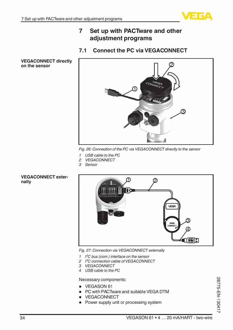
7.1 Connect the PC via VEGACONNECT
3
1
2
Fig. 26: Connection of the PC via VEGACONNECT directly to the sensor
1 USB cable to the PC 2 VEGACONNECT 3 Sensor
1 2
3
4
O P E N
TWIST
USB
L O C K
Fig. 27: Connection via VEGACONNECT externally
1 I²C bus (com.) interface on the sensor 2 I²C connection cable of VEGACONNECT 3 VEGACONNECT 4 USB cable to the PC
Necessary components:
• VEGASON 61
• PC with PACTware and suitable VEGA DTM
• VEGACONNECT
• Power supply unit or processing system
VEGACONNECT directlyon the sensor
VEGACONNECT exter-nally

8/12/2019 vega level-EN
http://slidepdf.com/reader/full/vega-level-en 35/52
35
7 Set up with PACTware and other adjustment programs
VEGASON 61 • 4 … 20 mA/HART - two-wire
2 8 7 7 5 - E N - 1 3 0 4 1 7
1
2 4
3 O P E N
T W I S T
U S B
L O C K
Fig. 28: Connecting the PC via HART to the signal cable
1 VEGASON 61 2 HART resistance 250 Ω (optional depending on processing)3 Connection cable with 2 mm pins and terminals4 Processing system/PLC/Voltage supply
Necessary components:• VEGASON 61
• PC with PACTware and suitable VEGA DTM
• VEGACONNECT
• HART resistance approx. 250 Ω
• Power supply unit or processing system
Note:
With power supply units with integrated HART resistance (internalresistance approx. 250 Ω), an additional external resistance is notnecessary. This applies, e. g. to the VEGA instruments VEGATRENN149A, VEGADIS 371, VEGAMET 381. Common Ex separators arealso usually equipped with a sucient current limitation resistance.
In such cases, VEGACONNECT 4 can be connected parallel to the4 … 20 mA cable.
7.2 Parameter adjustment with PACTwareFurther setup steps are described in the operating instructionsmanual "DTM Collection/PACTware" attached to each CD and which
can also be downloaded from our homepage. A detailed descriptionis available in the online help of PACTware and the VEGA DTMs.
Note:Keep in mind that for setup of VEGASON 61, DTM-Collection in theactual version must be used.
All currently available VEGA DTMs are included as a DTM Collectionon a CD. They can be purchased for a token fee from the responsibleVEGA agency. In addition, the actual PACTware version is also avail-able on this CD.
In addition, this DTM Collection incl. the basic version of PACTwarecan be downloaded free of charge from the Internet. Move via www.vega.com and "Downloads" to "Software".
VEGACONNECT via HART

8/12/2019 vega level-EN
http://slidepdf.com/reader/full/vega-level-en 36/52
36
7 Set up with PACTware and other adjustment programs
VEGASON 61 • 4 … 20 mA/HART - two-wire
2 8 7 7
5 -E N-1 3 0 4 1 7
7.3 Parameter adjustment with AMS™ and PDMFor VEGA sensors, instrument descriptions for the adjustmentprograms AMS™ and PDM are available as DD or EDD. The instru-ment descriptions are already implemented in the current versions ofAMS™ and PDM.
For older versions of AMS™ and PDM, a free-of-charge download isavailable via Internet. Move via www.vega.com and "Downloads" to"Software".
7.4 Saving the parameter adjustment dataIt is recommended to document or save the parameter adjustmentdata. That way they are available for multiple use or service purposes.
The VEGA DTM Collection and PACTware in the licensed, profession-al version provide suitable tools for systematic project documentationand storage.

8/12/2019 vega level-EN
http://slidepdf.com/reader/full/vega-level-en 37/52
37
8 Maintenance and fault rectication
VEGASON 61 • 4 … 20 mA/HART - two-wire
2 8 7 7 5 - E N - 1 3 0 4 1 7
8 Maintenance and fault rectication
8.1 MaintenanceIf the instrument is used properly, no special maintenance is required
in normal operation.
8.2 Rectify faults
The operator of the system is responsible for taking suitable meas-ures to rectify faults.
VEGASON 61 oers maximum reliability. Nevertheless, faults can oc-cur during operation. These may be caused by the following, e.g.:
• Sensor
• Process
• Voltage supply• Signal processing
The rst measures to be taken are to check the output signals as well
as to evaluate the error messages via the display and adjustmentmodule. The procedure is described below. Further comprehensivediagnostics can be carried out on a PC with the software PACTwareand the suitable DTM. In many cases, the causes can be determinedand the faults rectied this way.
Should these measures not be successful, please call in urgent cases
the VEGA service hotline under the phone no. +49 1805 858550.
The hotline is available to you 7 days a week round-the-clock. Sincewe oer this service world-wide, the support is only available in the
English language. The service is free of charge, only the standardtelephone costs will be charged.
Connect a handmultimeter in the suitable measuring range accordingto the wiring plan. The following table describes possible errors in thecurrent signal and helps to remove them:
Error Cause Rectication
4 … 20 mA signalnot stable
Level uctuations Set damping via the display and ad- justment module
4 … 20 mA signalmissing
Electrical connec-tion faulty
Check connection according tochapter "Connection steps" and ifnecessary, correct according to chap-ter "Wiring plan"
Voltage supplymissing
Check cables for breaks; repair if nec-essary
Operating voltagetoo low or load re-
sistance too high
Check, adapt if necessary
Reaction when malfunc-tions occur
Failure reasons
Fault rectication
24 hour service hotline
Check the 4 … 20 mAsignal

8/12/2019 vega level-EN
http://slidepdf.com/reader/full/vega-level-en 38/52
38
8 Maintenance and fault rectication
VEGASON 61 • 4 … 20 mA/HART - two-wire
2 8 7 7
5 -E N-1 3 0 4 1 7
Error Cause Rectication
Current sig-nal greater than22 mA or lessthan 3.6 mA
Electronics mod-ule in the sensordefective
Exchange the instrument or send it infor repair
In Ex applications, the regulations for the wiring of intrinsically safecircuits must be observed.
Error code Cause Rectication
E013 no measured valueavailable
– Sensor in boot phase – Sensor does not nd an echo, e.g.
due to faulty installation or wrongparameter adjustment
E017 Adjustment span toosmall
– Carry out a fresh adjustment andincrease the distance between min.and max. adjustment
E036 no operable sensorsoftware
– Carry out a software update or sendinstrument for repair
E041 Hardware error, elec-tronics defective
– Exchange the instrument or send itin for repair
Depending on the reason for the fault and the measures taken, thesteps described in chapter "Set up" may have to be carried out again.
8.3 Exchanging the electronics module
If the electronics module is defective, it can be replaced by the user.In Ex applications only one instrument and one electronics modulewith respective Ex approval may be used.
If there is no electronics module available on site, one can be orderedfrom the VEGA agency serving you.
The new electronics module must be loaded with the settings of thesensor. These are the options:
• At the factory by VEGA
• Or on site by the user
In both cases, the sensor serial number is necessary. The serial num-bers are stated on the type label of the instrument, inside the housingor on the delivery note.
Information:When loading on site, rst of all the order data must be downloadedfrom the Internet (see operating instructions manual "Electronicsmodule").
The electronics modules are adapted to the respective sensor anddistinguish also in the signal output or power supply.
8.4 Software updateThe software version of VEGASON 61 can be determined as follows:
Error messages via thedisplay and adjustmentmodule
Reaction after fault recti-cation
Sensor serial number
Assignment

8/12/2019 vega level-EN
http://slidepdf.com/reader/full/vega-level-en 39/52
39
8 Maintenance and fault rectication
VEGASON 61 • 4 … 20 mA/HART - two-wire
2 8 7 7 5 - E N - 1 3 0 4 1 7
• on the type label of the electronics
• Via the display and adjustment module
• via PACTware
You can view all software histories on our website www.vega.com.
Make use of this advantage and get registered for update information
via e-mail.
The following components are required to update the sensor soft-ware:
• Sensor
• Voltage supply
• VEGACONNECT
• PC with PACTware
• Current sensor software as le
At "www.vega.com/downloads" go to "Software". Select under " plicssensors and instruments", "Firmware updates" the respective instru-ment series and software version. Load the zip le via the right mousekey with "Save target as" e.g. on the desktop of your PC. Move withthe right mouse key to the folder and select "Extract all ". Save theextracted les, for example on the desktop.
Connect the signal conditioning instrument to power supply andprovide the connection from the PC to the instrument via the interfaceadapter. Start PACTware and go via the menu "Project " to the VEGA project assistant . Select "USB" and "Set instruments online". Activatethe project assistant with "Start ". The assistant establishes the con-nection automatically and opens the parameter adjustment window"Sensor # online parameter adjustment ". Connect this parameter
adjustment window before you carry out further steps.
Select with the right mouse key the sensor in the project and go to" Additional function". Then click to "Software update". The window
"Sensor # software update" opens. PACTware checks now the sensordata and displays the actual hardware and software version of thesensor. This takes approximately 60 s.
Push the button "Update software" and select the previously extracted
hex le. Then the software update can be started. The additional lesare installed automatically. Depending on the sensor, this procedurelasts up to 1 h. Then the message appears ""Software update suc-cessfully executed ".
8.5 Instrument repairIf a repair is necessary, please proceed as follows:
You can download a return form (23 KB) from our Internet homepagewww.vega.com under: "Downloads - Forms and certifcates - Repairform".
By doing this you help us carry out the repair quickly and without hav-ing to call back for needed information.
• Print and ll out one form per instrument
Load sensor softwareto PC
Prepare update
Load software into sen-sor

8/12/2019 vega level-EN
http://slidepdf.com/reader/full/vega-level-en 40/52
40
8 Maintenance and fault rectication
VEGASON 61 • 4 … 20 mA/HART - two-wire
2 8 7 7
5 -E N-1 3 0 4 1 7
• Clean the instrument and pack it damage-proof
• Attach the completed form and, if need be, also a safety datasheet outside on the packaging
• Please ask the agency serving you for the address of your returnshipment. You can nd the respective contact data on our website
www.vega.com under: "Company - VEGA worldwide"

8/12/2019 vega level-EN
http://slidepdf.com/reader/full/vega-level-en 41/52
41
9 Dismounting
VEGASON 61 • 4 … 20 mA/HART - two-wire
2 8 7 7 5 - E N - 1 3 0 4 1 7
9 Dismounting
9.1 Dismounting steps
Warning:
Before dismounting, be aware of dangerous process conditions suchas e.g. pressure in the vessel, high temperatures, corrosive or toxicproducts etc.
Take note of chapters "Mounting" and "Connecting to power supply "and carry out the listed steps in reverse order.
9.2 DisposalThe instrument consists of materials which can be recycled by spe-cialised recycling companies. We use recyclable materials and havedesigned the parts to be easily separable.
WEEE directive 2002/96/EGThis instrument is not subject to the WEEE directive 2002/96/EG andthe respective national laws. Pass the instrument directly on to a spe-cialised recycling company and do not use the municipal collectingpoints. These may be used only for privately used products accordingto the WEEE directive.
Correct disposal avoids negative eects on humans and the environ-ment and ensures recycling of useful raw materials.
Materials: see chapter "Technical data"
If you have no way to dispose of the old instrument properly, pleasecontact us concerning return and disposal.

8/12/2019 vega level-EN
http://slidepdf.com/reader/full/vega-level-en 42/52
42
10 Supplement
VEGASON 61 • 4 … 20 mA/HART - two-wire
2 8 7 7
5 -E N-1 3 0 4 1 7
10 Supplement
10.1 Technical dataGeneral data
Materials, wetted parts
Ʋ Process tting, transducer PVDF
Ʋ Seal between transducer and processtting
EPDM, FKM (Viton)
Materials, non-wetted parts
Ʋ Housing Plastic PBT (polyester), Alu die-casting powder-coated,316L
Ʋ Seal between housing and housingcover
NBR (stainless steel housing), silicone (Alu/plastic hous-ing)
Ʋ Inspection window in housing cover Polycarbonate
Ʋ Ground terminal 316Ti/316L
Weight 1.8 … 4 kg (4 … 8.8 lbs), depending on the processtting and housing
Max. torque mounting boss 25 Nm
Output variable
Output signal 4 … 20 mA/HART
HART output values
Ʋ HART value (Primary Value) Distance to the level
Ʋ HART value (Secondary Value) Temperature
Ʋ HART value (3rd Value) Distance to the level - scaled
Signal resolution 1.6 µA
Failure signal current output (adjustable) mA-value unchanged 20.5 mA, 22 mA, < 3.6 mA
Current limitation 22 mA
Load see load diagram under Power supply
Damping (63 % of the input variable) 0 … 999 s, adjustable
Met NAMUR recommendation NE 43
Input variable
Measured variable distance between lower edge of the transducer andproduct surface
Measuring range
Ʋ Liquids up to 5 m (16.4 ft)
Ʋ Bulk solids up to 2 m (6.562 ft)
Dead band 0.25 m (0.82 ft)
Reference conditions to measuring accuracy (according to DIN EN 60770-1)
Reference conditions according to DIN EN 61298-1 Ʋ Temperature +18 … +30 °C (+64 … +86 °F)
Ʋ Relative humidity 45 … 75 %

8/12/2019 vega level-EN
http://slidepdf.com/reader/full/vega-level-en 43/52
43
10 Supplement
VEGASON 61 • 4 … 20 mA/HART - two-wire
2 8 7 7 5 - E N - 1 3 0 4 1 7
Ʋ Air pressure 860 … 1060 mbar/86 … 106 kPa (12.5 … 15.4 psig)
Other reference conditions
Ʋ Reector ideal reector, e.g. metal plate 2 x 2 m (6.56 x 6.56 ft)
Ʋ False reections Biggest false signal, 20 dB smaller than the useful signal
Measuring characteristics
Ultrasonic frequency 70 kHz
Interval > 2 s (dependent on the parameter adjustment)
Abstrahlwinkel at -3 dB 11°
Step response or adjustment time4) > 3 s (dependent on the parameter adjustment)
Measuring accuracy
Resolution, general > 1 mm (0.039 in)
Deviation5) see diagram
5 m (16.404 ft)4 m (13.123 ft)3 m (9.843 ft)2 m (6.562 ft)1 m (3.28 ft)
10 mm (0.394 in)
4 mm (0.157 in)
-10 mm (-0.394 in)
-4 mm (-0.157 in)
Fig. 29: Deviation VEGASON 61
Inuence of the ambient temperature to the sensor electronics6)
Average temperature coecient of thezero signal (temperature error)
0.06 %/10 K
Ambient conditions
Ambient, storage and transport tempera-ture
-40 … +80 °C (-40 … +176 °F)
Process conditionsProcess pressure -20 … 200 kPa/-0.2 … 2 bar (-2.9 … 29 psig)
Process temperature (transducer tem-perature)
-40 … +80 °C (-40 … +176 °F)
Vibration resistance mechanical vibrations with 4 g and 5 … 100 Hz7)
Electromechanical data - version IP 66/IP 67 and IP 66/IP 68; 0.2 bar
Cable entry/plug8)
4)
Time to output the correct level (with max. 10 % deviation) after a sudden level change.5) Incl. non-linearity, hysteresis and non-repeatability.6) Relating to the nominal measuring range.7) Tested according to the guidelines of German Lloyd, GL directive 2.8) Depending on the version M12 x 1, according to DIN 43650, Harting, 7/8" FF.
8/12/2019 vega level-EN
http://slidepdf.com/reader/full/vega-level-en 44/52
44
10 Supplement
VEGASON 61 • 4 … 20 mA/HART - two-wire
2 8 7 7
5 -E N-1 3 0 4 1 7
Ʋ Single chamber housing – 1 x cable gland M20 x 1.5 (cable: ø 5 … 9 mm), 1 x
blind plug M20 x 1.5or:
– 1 x closing cap M20 x 1.5; 1 x blind plug M20 x 1.5or:
– 1 x closing cap ½ NPT, 1 x blind plug ½ NPTor:
– 1x plug (depending on the version), 1x blind stopperM20x1.5
Ʋ Double chamber housing – 1 x cable entry M20 x 1.5 (cable: ø 5 … 9 mm), 1 xblind plug M20 x 1.5; 1 x blind plug M16 x 1.5 or
optionally available with 1 x plug M12 x 1 for externaldisplay and adjustment unit
or:
– 1 x closing cap ½ NPT, 1 x blind plug ½ NPT, 1 x blindplug M16 x 1.5 or optionally 1 x plug M12 x 1 for exter-nal display and adjustment unit
or:
– 1 x plug (depending on the version), 1 x blind plugM20 x 1.5; 1 x blind plug M16 x 1.5 or optionally avail-able with 1 x plug M12 x 1 for external display and
adjustment unit
Spring-loaded terminals for wire cross-section
< 2.5 mm² (AWG 14)
Electromechanical data - version IP 66/IP 68 (1 bar)Cable entry
Ʋ Single chamber housing 1 x IP 68 cable gland M20 x 1.5; 1 x blind plug M20 x 1.5
Ʋ Double chamber housing 1x IP68 cable gland M20x1.5; 1x blind stopperM20x1.5; 1x blind stopper M16x1.5
Connection cable
Ʋ Wire cross-section 0.5 mm² (AWG 20)
Ʋ Wire resistance < 0.036 Ω/m (0.011 Ω/ft)
Ʋ Tensile strength < 1200 N (270 lbf)
Ʋ Standard length 5 m (16.4 ft) Ʋ Max. length 1000 m (3280 ft)
Ʋ Min. bending radius 25 mm (0.984 in) with 25 °C (77 °F)
Ʋ Diameter approx. 8 mm (0.315 in)
Ʋ Colour - standard PE Black
Ʋ Colour - standard PUR Blue
Ʋ Colour - Ex-version Blue
Display and adjustment module
Voltage supply and data transmission through the sensorIndication LC display in dot matrix
Adjustment elements 4 keys

8/12/2019 vega level-EN
http://slidepdf.com/reader/full/vega-level-en 45/52
45
10 Supplement
VEGASON 61 • 4 … 20 mA/HART - two-wire
2 8 7 7 5 - E N - 1 3 0 4 1 7
Protection rating
Ʋ unassembled IP 20
Ʋ mounted into the sensor without cover IP 40
Material
Ʋ Housing ABS Ʋ Inspection window Polyester foil
Voltage supply
Operating voltage
Ʋ Non-Ex instrument 14 … 36 V DC
Ʋ Ex-ia instrument 14 … 30 V DC
Operating voltage with illuminated display and adjustment module
Ʋ Non-Ex instrument 20 … 36 V DC
Ʋ Ex-ia instrument 20 … 30 V DCPermissible residual ripple
Ʋ < 100 Hz Uss
< 1 V
Ʋ 100 Hz … 10 kHz Uss
< 10 mV
Load see diagram
1000
750
500
250
14 1816 20 22 24 26 28 30 32 34 36
Ω
V
4
1 2
3
Fig. 30: Voltage diagram
1 HART load 2 Voltage limit Ex-ia instrument 3 Voltage limit non-Ex instrument 4 Operating voltage
Electrical protective measures
Protection, depending on housing version
Ʋ Plastic housing IP 66/IP 67
Ʋ Aluminium housing, stainless steelhousing - investment casting, stain-less steel housing - electro-polished
IP 66/IP 68 (0.2 bar)9)
Ʋ Aluminium and stainless housing, in-
vestment casting (optionally available)
IP 66/IP 68 (1 bar)
9) A suitable cable is the prerequisite for maintaining the protection rating.

8/12/2019 vega level-EN
http://slidepdf.com/reader/full/vega-level-en 46/52
46
10 Supplement
VEGASON 61 • 4 … 20 mA/HART - two-wire
2 8 7 7
5 -E N-1 3 0 4 1 7
Overvoltage category III
Protection class II
Functional safety (SIL)
Functional safety is already activated on instruments with SIL qualication ex factory. On instru-
ments without SIL qualication ex factory, the functional safety must be activated by the user viathe display and adjustment module or via PACTware for applications according to SIL.
Functional safety according to IEC 61508-4
Ʋ Single channel architecture (1oo1D) up to SIL2
Ʋ double channel diversitary redundantarchitecture (1oo2D)
up to SIL3
You can nd detailed information in the supplied Safety Manual of the instrument series or under"www.vega.com", "Downloads", " Approvals".
Approvals
Instruments with approvals can have dierent technical data depending on the version.
For that reason the associated approval documents of these instruments have to be carefullynoted. They are part of the delivery or can be downloaded under www.vega.com via "VEGA Tools"and "serial number search" as well as via "Downloads" and " Approvals".
8/12/2019 vega level-EN
http://slidepdf.com/reader/full/vega-level-en 47/52
47
10 Supplement
VEGASON 61 • 4 … 20 mA/HART - two-wire
2 8 7 7 5 - E N - 1 3 0 4 1 7
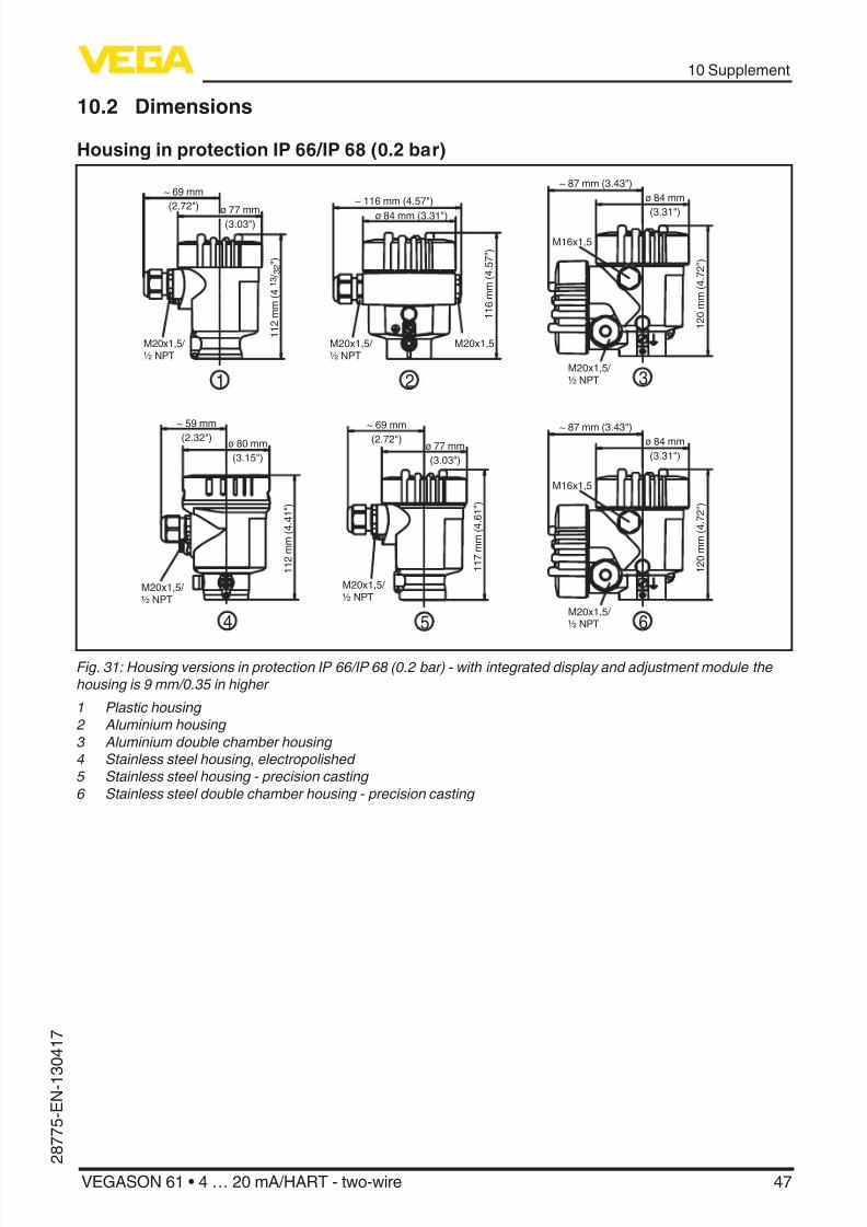
10.2 Dimensions
Housing in protection IP 66/IP 68 (0.2 bar)
~ 69 mm
(2.72")
ø 77 mm(3.03")
1 1 2 m m ( 4
1 3 / 3 2 " )
M20x1,5/
½ NPT
~ 69 mm(2.72")
ø 77 mm
(3.03")
1 1 7 m m ( 4 . 6
1 " )
M20x1,5/
½ NPT
~ 87 mm (3.43")
M16x1,5
ø 84 mm
(3.31")
1 2 0 m m ( 4 . 7
2 " )
M20x1,5/
½ NPT
~ 87 mm (3.43")
M16x1,5
ø 84 mm
(3.31")
1 2 0 m m ( 4 . 7
2 " )
M20x1,5/ ½ NPT
~ 116 mm (4.57")
ø 84 mm (3.31")
1 1 6 m m ( 4 . 5
7 " )
M20x1,5M20x1,5/
½ NPT
~ 59 mm
(2.32")ø 80 mm
(3.15")
1 1 2 m m ( 4 . 4
1 " )
M20x1,5/
½ NPT
1
5
3
6
2
4
Fig. 31: Housing versions in protection IP 66/IP 68 (0.2 bar) - with integrated display and adjustment module thehousing is 9 mm/0.35 in higher
1 Plastic housing 2 Aluminium housing3 Aluminium double chamber housing4 Stainless steel housing, electropolished 5 Stainless steel housing - precision casting6 Stainless steel double chamber housing - precision casting

8/12/2019 vega level-EN
http://slidepdf.com/reader/full/vega-level-en 48/52
48
10 Supplement
VEGASON 61 • 4 … 20 mA/HART - two-wire
2 8 7 7
5 -E N-1 3 0 4 1 7
Housing in protection IP 66/IP 68 (1 bar)
1 1 7 m m ( 4 . 6
1 " )
~ 103 mm
(4.06")ø 77 mm
(3.03")
1 1 6 m m ( 4 . 5
7 " )
~ 150 mm (5.91")
ø 84 mm (3.31")
1 2 0 m m ( 4 . 7
2 " )
~ 105 mm (4.13")
ø 84 mm
(3.31")
M20x1,5
2M20x1,5/ ½ NPT
M16x1,5
3
M20x1,5M20x1,5
1
Fig. 32: Housing versions in protection IP66/IP68 (1bar) - with integrated display and adjustment module thehousing is 9mm/0.35in higher
1 Aluminium housing
2 Stainless steel housing - precision casting 2 Stainless steel double chamber housing - precision casting
VEGASON 61
1 2
1 5 5 m m ( 6
7 / 6 4 " )
2 2 m m ( 5
5 / 6 4 " )
6 6 m m
( 2 1 9 / 3 2 " )
ø 39mm
(1 17 / 32")
ø 74mm(2 58 / 64")
60mm
(2 23 / 64")
G1½A /
1½"NPT
Fig. 33: VEGASON 61
1 Dead zone: 0.25 m (0.82 ft) 2 Measuring range: with liquids up to 5 m (16.4 ft), with solids up to 2 m (6.562 ft)

8/12/2019 vega level-EN
http://slidepdf.com/reader/full/vega-level-en 49/52
49
10 Supplement
VEGASON 61 • 4 … 20 mA/HART - two-wire
2 8 7 7 5 - E N - 1 3 0 4 1 7
10.3 Industrial property rights
VEGA product lines are global protected by industrial property rights. Further information seewww.vega.com.
Only in U.S.A.: Further information see patent label at the sensor housing.
VEGA Produktfamilien sind weltweit geschützt durch gewerbliche Schutzrechte.Nähere Informationen unter www.vega.com.
Les lignes de produits VEGA sont globalement protégées par des droits de propriété intellec-tuelle. Pour plus d'informations, on pourra se référer au site www.vega.com.
VEGA lineas de productos están protegidas por los derechos en el campo de la propiedad indus-trial. Para mayor información revise la pagina web www.vega.com.
Линии продукции фирмы ВЕГА защищаются по всему миру правами на интеллектуальнуюсобственность. Дальнейшую информацию смотрите на сайте www.vega.com.
VEGA系列产品在全球享有知识产权保护。
进一步信息请参见网站<www.vega.com>。
10.4 TrademarkAll the brands as well as trade and company names used are property of their lawful proprietor/ originator.

8/12/2019 vega level-EN
http://slidepdf.com/reader/full/vega-level-en 50/52
50
Notes
VEGASON 61 • 4 … 20 mA/HART - two-wire
2 8 7 7
5 -E N-1 3 0 4 1 7

8/12/2019 vega level-EN
http://slidepdf.com/reader/full/vega-level-en 51/52
51
Notes
VEGASON 61 • 4 … 20 mA/HART - two-wire
2 8 7 7 5 - E N - 1 3 0 4 1 7
8/12/2019 vega level-EN
http://slidepdf.com/reader/full/vega-level-en 52/52
Printing date:
2 8 7 7 5 - E N - 1 3 0 4 1 7 All statements concerning scope of delivery, application, practical use and operat-
ing conditions of the sensors and processing systems correspond to the information
available at the time of printing.
Subject to change without prior notice
© VEGA Grieshaber KG, Schiltach/Germany 2013