vehicle engine cooling system simulation (vecss) … · vehicle engine cooling system simulation...
TRANSCRIPT
Michigan Technological University ResearchLuptowski, Arici, Johnson, Parker
GT-Suite Users Conference Nov. 18, 2002
ByBrian J. Luptowski
Michigan Technological UniversityDepartment of Mechanical Engineering - Engineering Mechanics
Vehicle Engine Cooling System Simulation (VECSS) Utilizing GT-Power
Funding Provided by the Army Research Office
Michigan Technological University ResearchLuptowski, Arici, Johnson, Parker
GT-Suite Users Conference Nov. 18, 2002
Motivation• Fuel economy
• System design, performance, and component sizing
• Simulation of advanced computer controlled (“smart”) cooling systems in vehicles necessitates the coupling of commercially available cycle analysis software (GT-Power) to vehicle and engine fluid flow systems
Goals
• Develop a code capable of energy based cooling control and multi-variable optimization
• Conduct advanced component analysis (electric fan, electric coolant pump, actuators) to achieve reduced accessory power and improved engine temperature control
Michigan Technological University ResearchLuptowski, Arici, Johnson, Parker
GT-Suite Users Conference Nov. 18, 2002
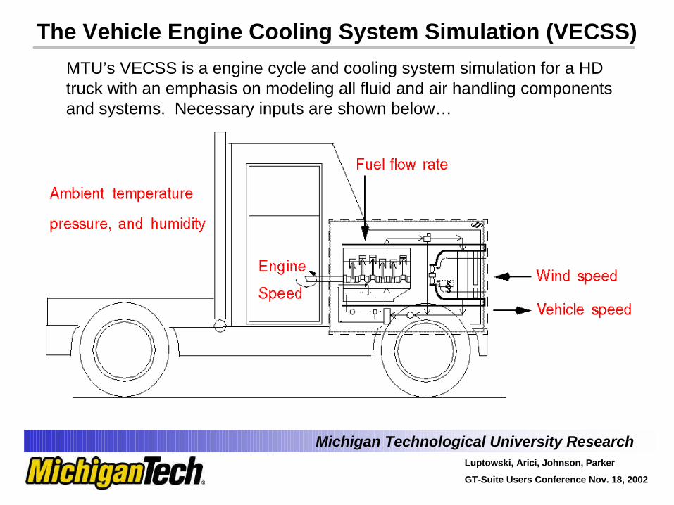
The Vehicle Engine Cooling System Simulation (VECSS)
MTU’s VECSS is a engine cycle and cooling system simulation for a HD truck with an emphasis on modeling all fluid and air handling components and systems. Necessary inputs are shown below…
Michigan Technological University ResearchLuptowski, Arici, Johnson, Parker
GT-Suite Users Conference Nov. 18, 2002
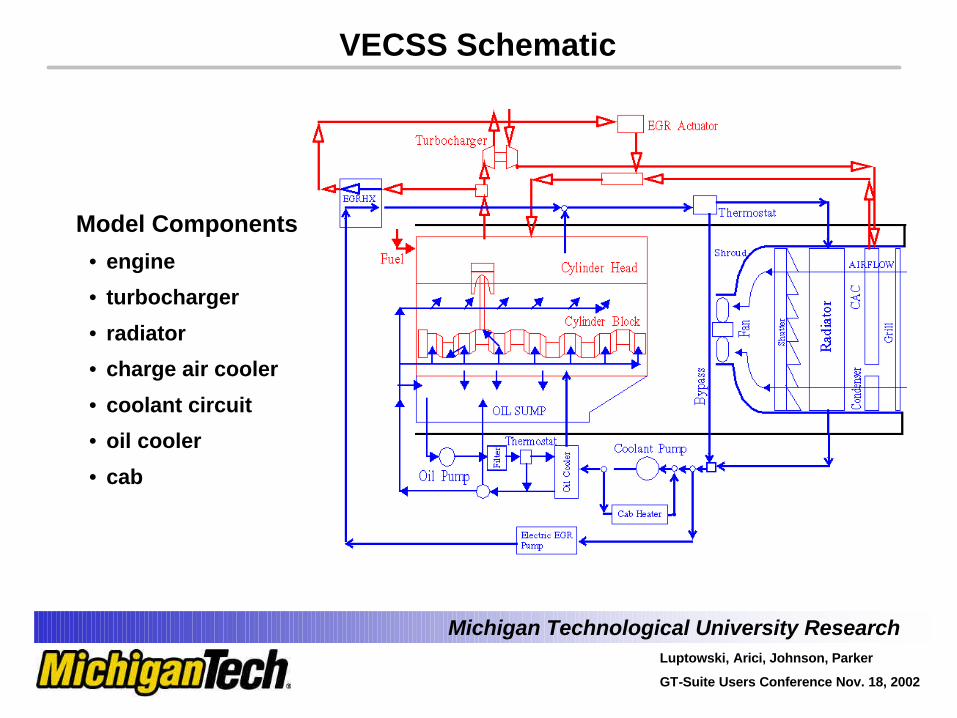
Model Components
• engine
• turbocharger
• radiator
• charge air cooler
• coolant circuit
• oil cooler
• cab
VECSS Schematic
Michigan Technological University ResearchLuptowski, Arici, Johnson, Parker
GT-Suite Users Conference Nov. 18, 2002
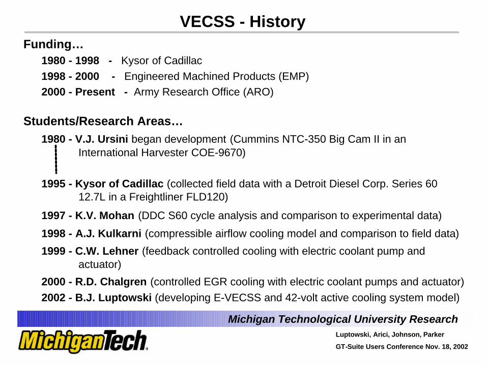
Funding…1980 - 1998 - Kysor of Cadillac1998 - 2000 - Engineered Machined Products (EMP)2000 - Present - Army Research Office (ARO)
Students/Research Areas…1980 - V.J. Ursini began development (Cummins NTC-350 Big Cam II in an
International Harvester COE-9670)
1995 - Kysor of Cadillac (collected field data with a Detroit Diesel Corp. Series 60 12.7L in a Freightliner FLD120)
1997 - K.V. Mohan (DDC S60 cycle analysis and comparison to experimental data)
1998 - A.J. Kulkarni (compressible airflow cooling model and comparison to field data)
1999 - C.W. Lehner (feedback controlled cooling with electric coolant pump and actuator)
2000 - R.D. Chalgren (controlled EGR cooling with electric coolant pumps and actuator)2002 - B.J. Luptowski (developing E-VECSS and 42-volt active cooling system model)
VECSS - History
Michigan Technological University ResearchLuptowski, Arici, Johnson, Parker
GT-Suite Users Conference Nov. 18, 2002
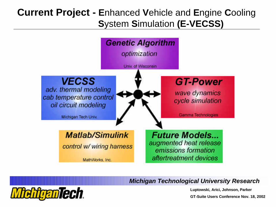
Current Project - Enhanced Vehicle and Engine Cooling System Simulation (E-VECSS)
Michigan Technological University ResearchLuptowski, Arici, Johnson, Parker
GT-Suite Users Conference Nov. 18, 2002
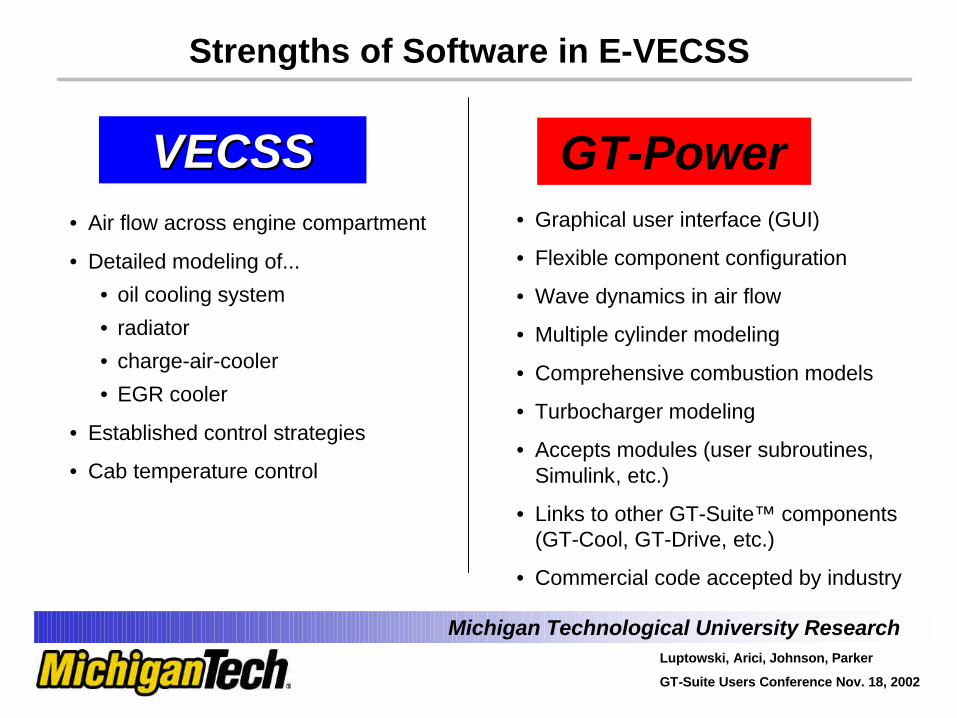
• Air flow across engine compartment
• Detailed modeling of...
• oil cooling system
• radiator
• charge-air-cooler
• EGR cooler
• Established control strategies
• Cab temperature control
VECSSVECSS• Graphical user interface (GUI)
• Flexible component configuration
• Wave dynamics in air flow
• Multiple cylinder modeling
• Comprehensive combustion models
• Turbocharger modeling
• Accepts modules (user subroutines,Simulink, etc.)
• Links to other GT-Suite™ components (GT-Cool, GT-Drive, etc.)
• Commercial code accepted by industry
GT-Power
Strengths of Software in E-VECSS
Michigan Technological University ResearchLuptowski, Arici, Johnson, Parker
GT-Suite Users Conference Nov. 18, 2002
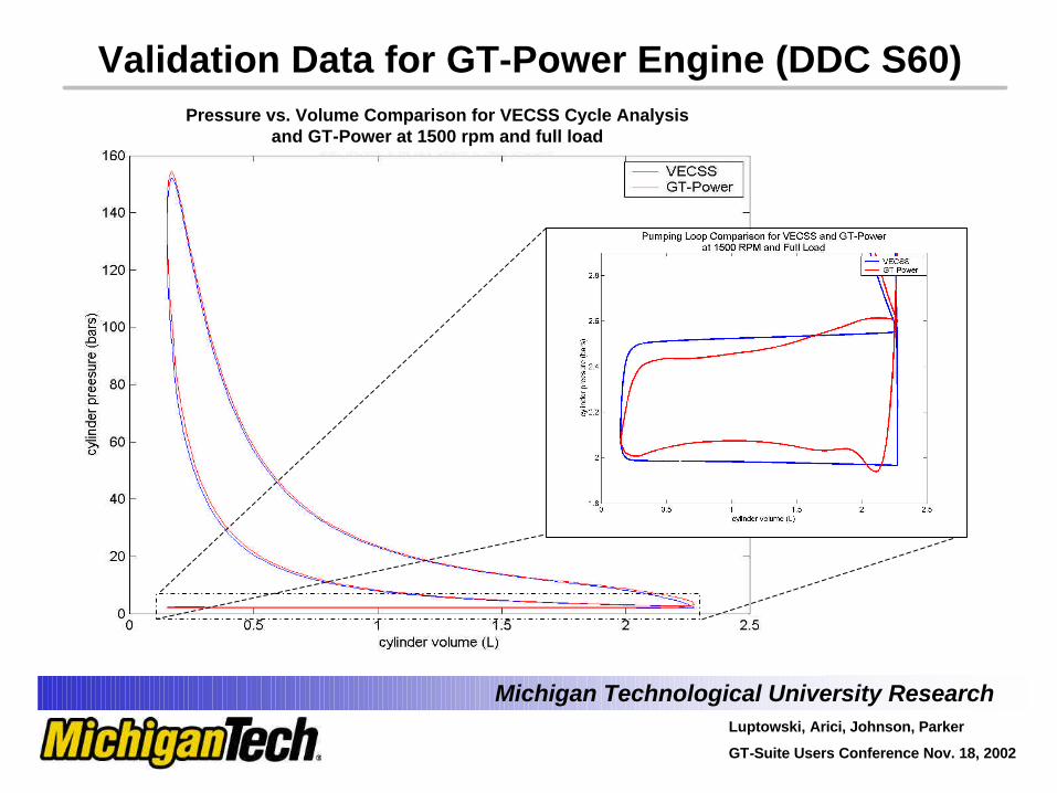
Validation Data for GT-Power Engine (DDC S60) Pressure vs. Volume Comparison for VECSS Cycle Analysis
and GT-Power at 1500 rpm and full load
Michigan Technological University ResearchLuptowski, Arici, Johnson, Parker
GT-Suite Users Conference Nov. 18, 2002
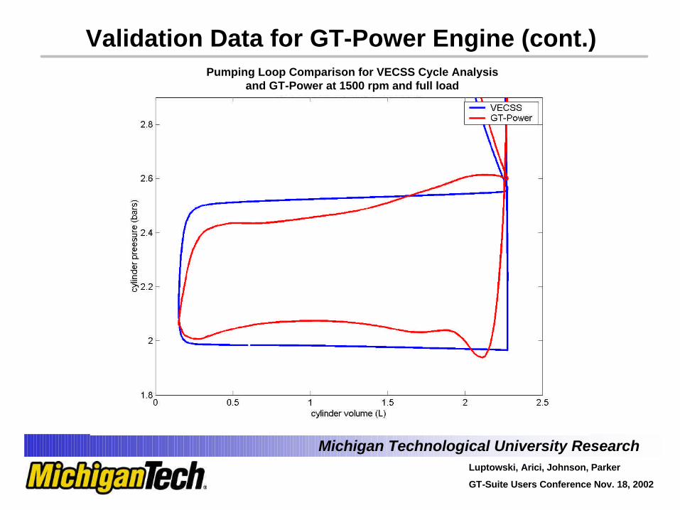
Validation Data for GT-Power Engine (cont.)Pumping Loop Comparison for VECSS Cycle Analysis
and GT-Power at 1500 rpm and full load
Michigan Technological University ResearchLuptowski, Arici, Johnson, Parker
GT-Suite Users Conference Nov. 18, 2002
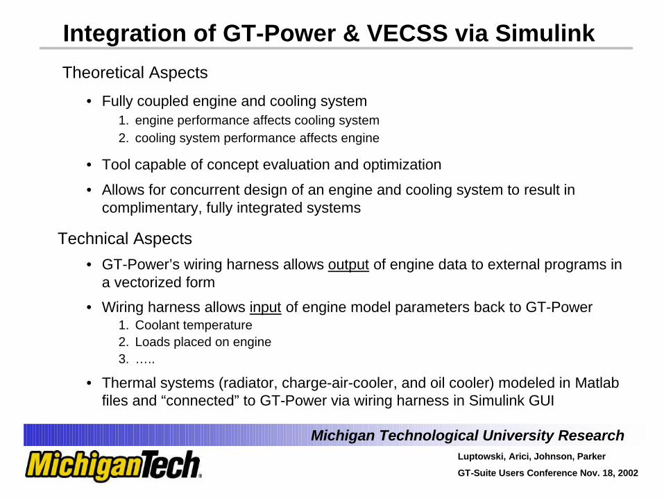
Integration of GT-Power & VECSS via Simulink
Theoretical Aspects
• Fully coupled engine and cooling system1. engine performance affects cooling system2. cooling system performance affects engine
• Tool capable of concept evaluation and optimization
• Allows for concurrent design of an engine and cooling system to result in complimentary, fully integrated systems
Technical Aspects
• GT-Power’s wiring harness allows output of engine data to external programs in a vectorized form
• Wiring harness allows input of engine model parameters back to GT-Power1. Coolant temperature2. Loads placed on engine3. …..
• Thermal systems (radiator, charge-air-cooler, and oil cooler) modeled in Matlabfiles and “connected” to GT-Power via wiring harness in Simulink GUI
Michigan Technological University ResearchLuptowski, Arici, Johnson, Parker
GT-Suite Users Conference Nov. 18, 2002
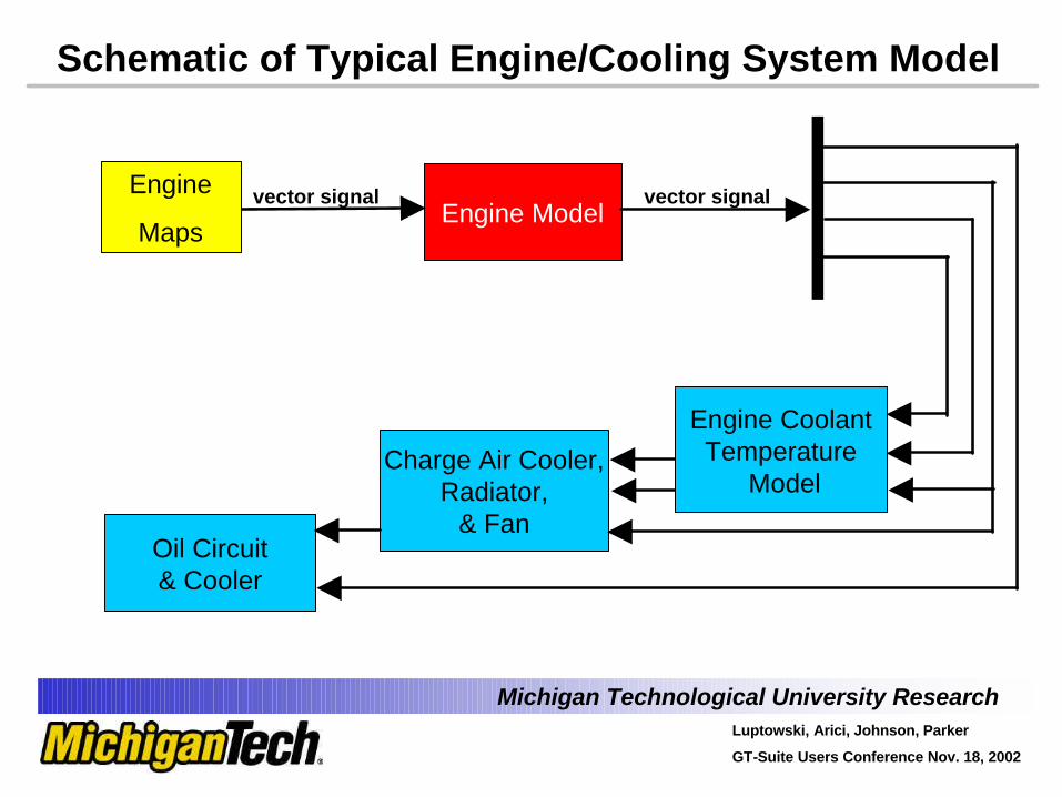
Schematic of Typical Engine/Cooling System Model
Engine Model
Charge Air Cooler,Radiator,
& Fan
Engine Thermal Model
Oil Circuit& Cooler
Engine
Maps
Engine CoolantTemperature
Model
vector signalvector signal
Michigan Technological University ResearchLuptowski, Arici, Johnson, Parker
GT-Suite Users Conference Nov. 18, 2002
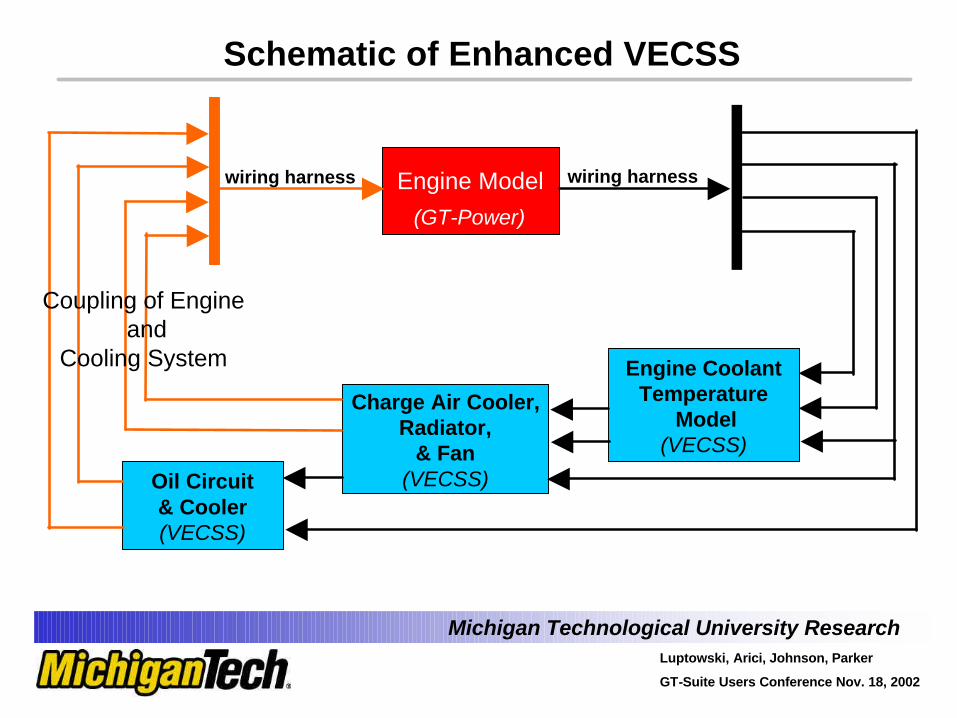
Schematic of Enhanced VECSS
Engine Model wiring harness
Charge Air Cooler,Radiator,
& Fan(VECSS)
Engine CoolantTemperature
Model(VECSS)
Oil Circuit& Cooler(VECSS)
wiring harness
Coupling of Engineand
Cooling System
(GT-Power)
Michigan Technological University ResearchLuptowski, Arici, Johnson, Parker
GT-Suite Users Conference Nov. 18, 2002
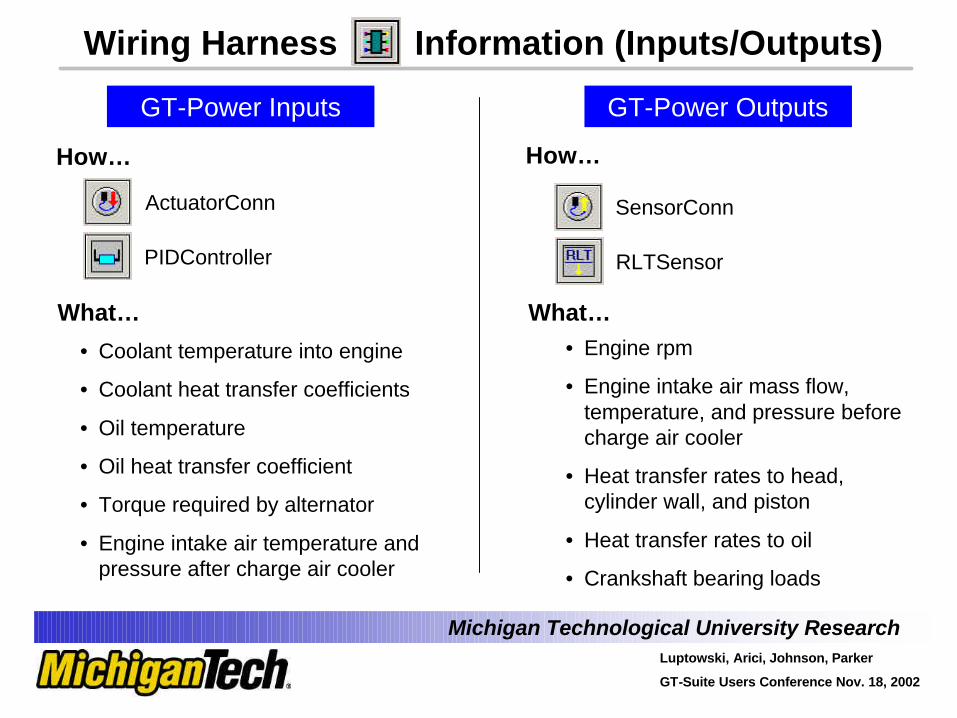
Wiring Harness Information (Inputs/Outputs)
RLTSensor
SensorConn
• Engine rpm
• Engine intake air mass flow, temperature, and pressure before charge air cooler
• Heat transfer rates to head, cylinder wall, and piston
• Heat transfer rates to oil
• Crankshaft bearing loads
GT-Power Outputs
How…
What…
• Coolant temperature into engine
• Coolant heat transfer coefficients
• Oil temperature
• Oil heat transfer coefficient
• Torque required by alternator
• Engine intake air temperature and pressure after charge air cooler
GT-Power Inputs
How…
What…
ActuatorConn
PIDController
Michigan Technological University ResearchLuptowski, Arici, Johnson, Parker
GT-Suite Users Conference Nov. 18, 2002
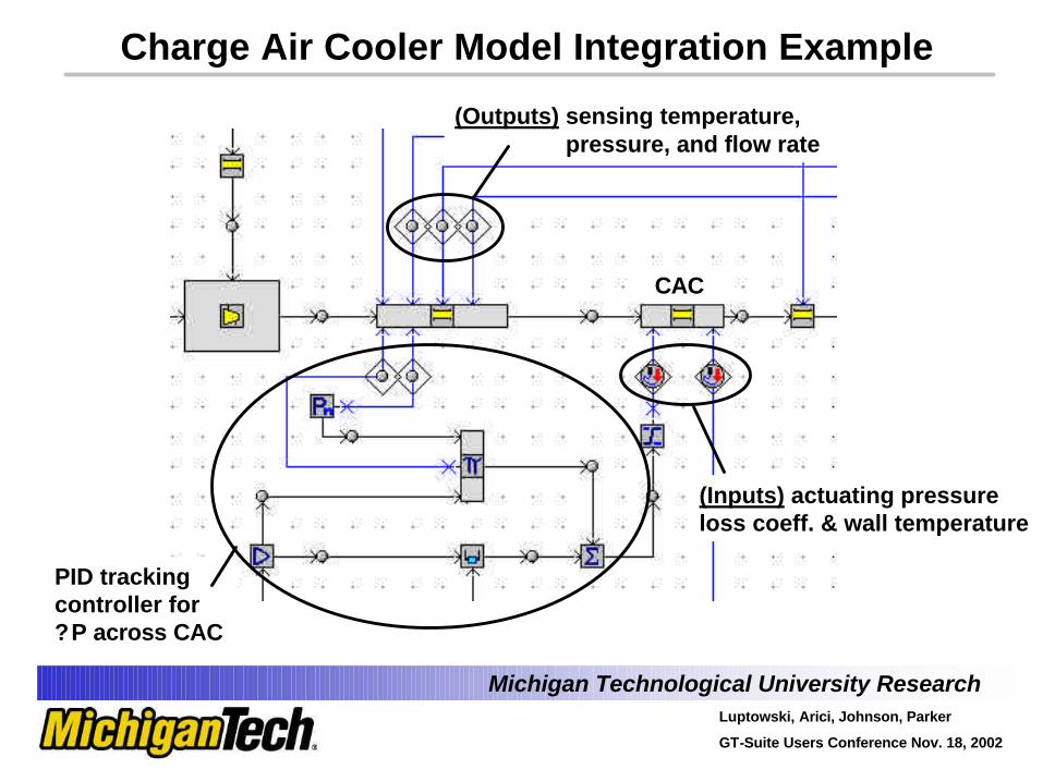
Charge Air Cooler Model Integration Example
(Outputs) sensing temperature,pressure, and flow rate
(Inputs) actuating pressure loss coeff. & wall temperature
PID tracking controller for?P across CAC
CAC
Michigan Technological University ResearchLuptowski, Arici, Johnson, Parker
GT-Suite Users Conference Nov. 18, 2002
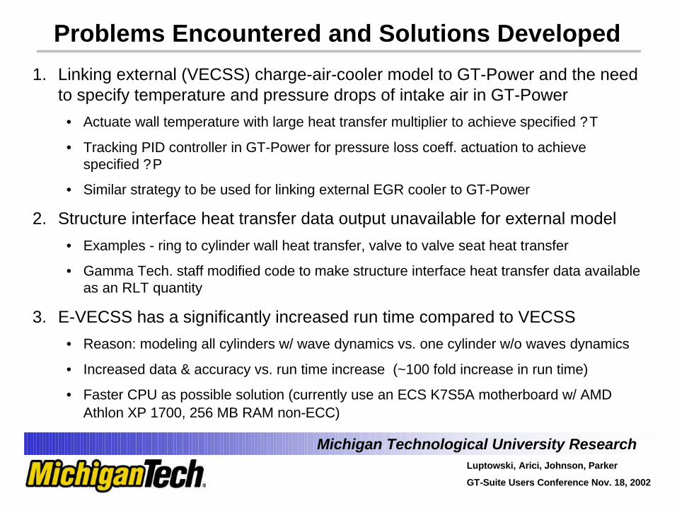
Problems Encountered and Solutions Developed
1. Linking external (VECSS) charge-air-cooler model to GT-Power and the need to specify temperature and pressure drops of intake air in GT-Power
• Actuate wall temperature with large heat transfer multiplier to achieve specified ?T
• Tracking PID controller in GT-Power for pressure loss coeff. actuation to achieve specified ?P
• Similar strategy to be used for linking external EGR cooler to GT-Power
2. Structure interface heat transfer data output unavailable for external model
• Examples - ring to cylinder wall heat transfer, valve to valve seat heat transfer
• Gamma Tech. staff modified code to make structure interface heat transfer data available as an RLT quantity
3. E-VECSS has a significantly increased run time compared to VECSS
• Reason: modeling all cylinders w/ wave dynamics vs. one cylinder w/o waves dynamics
• Increased data & accuracy vs. run time increase (~100 fold increase in run time)
• Faster CPU as possible solution (currently use an ECS K7S5A motherboard w/ AMD Athlon XP 1700, 256 MB RAM non-ECC)
Michigan Technological University ResearchLuptowski, Arici, Johnson, Parker
GT-Suite Users Conference Nov. 18, 2002
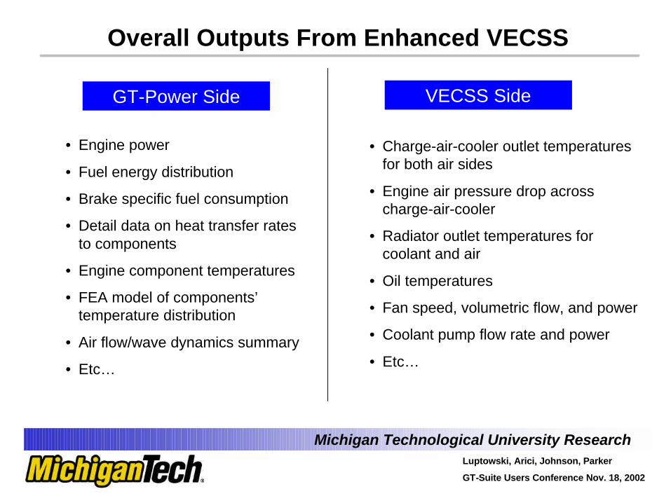
Overall Outputs From Enhanced VECSS
• Engine power
• Fuel energy distribution
• Brake specific fuel consumption
• Detail data on heat transfer rates to components
• Engine component temperatures
• FEA model of components’ temperature distribution
• Air flow/wave dynamics summary
• Etc…
GT-Power Side
• Charge-air-cooler outlet temperatures for both air sides
• Engine air pressure drop across charge-air-cooler
• Radiator outlet temperatures for coolant and air
• Oil temperatures
• Fan speed, volumetric flow, and power
• Coolant pump flow rate and power
• Etc…
VECSS Side
Michigan Technological University ResearchLuptowski, Arici, Johnson, Parker
GT-Suite Users Conference Nov. 18, 2002
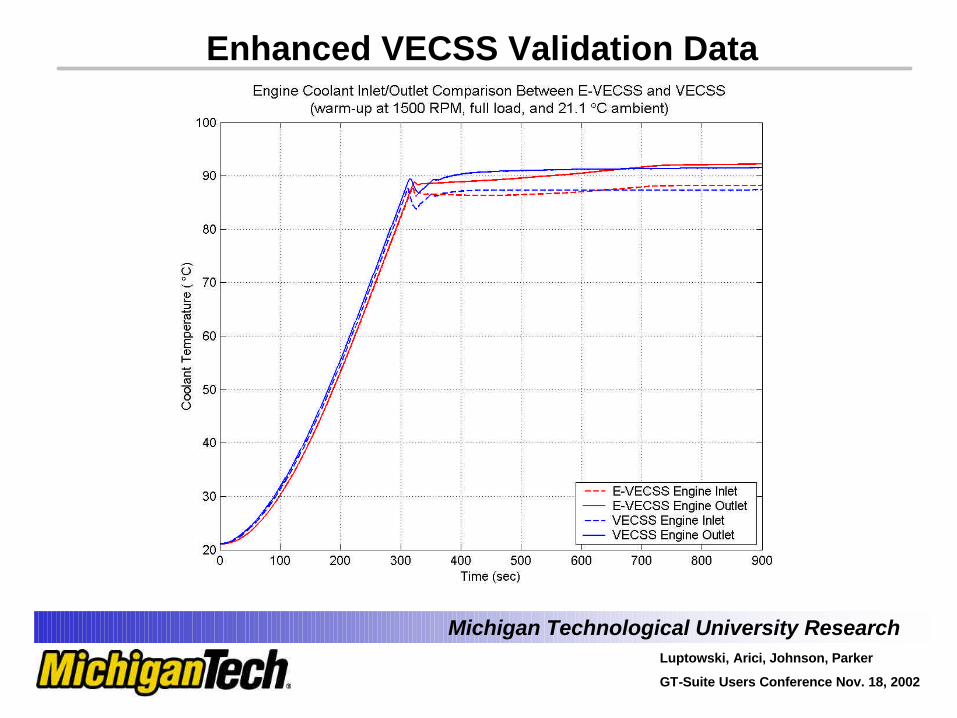
Enhanced VECSS Validation Data
Michigan Technological University ResearchLuptowski, Arici, Johnson, Parker
GT-Suite Users Conference Nov. 18, 2002
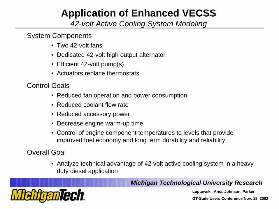
Application of Enhanced VECSS42-volt Active Cooling System Modeling
System Components• Two 42-volt fans• Dedicated 42-volt high output alternator• Efficient 42-volt pump(s)• Actuators replace thermostats
Control Goals• Reduced fan operation and power consumption• Reduced coolant flow rate• Reduced accessory power• Decrease engine warm-up time• Control of engine component temperatures to levels that provide
improved fuel economy and long term durability and reliability
Overall Goal
• Analyze technical advantage of 42-volt active cooling system in a heavy duty diesel application
Michigan Technological University ResearchLuptowski, Arici, Johnson, Parker
GT-Suite Users Conference Nov. 18, 2002
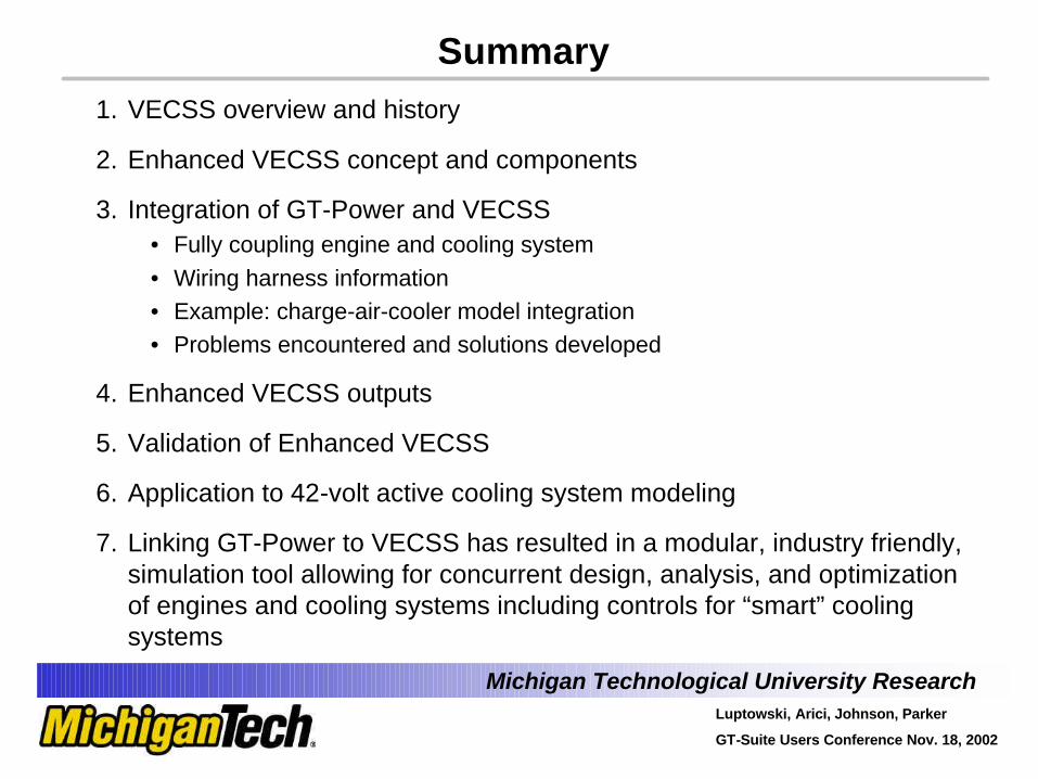
Summary1. VECSS overview and history
2. Enhanced VECSS concept and components
3. Integration of GT-Power and VECSS• Fully coupling engine and cooling system• Wiring harness information• Example: charge-air-cooler model integration• Problems encountered and solutions developed
4. Enhanced VECSS outputs
5. Validation of Enhanced VECSS
6. Application to 42-volt active cooling system modeling
7. Linking GT-Power to VECSS has resulted in a modular, industry friendly, simulation tool allowing for concurrent design, analysis, and optimization of engines and cooling systems including controls for “smart” cooling systems
Michigan Technological University ResearchLuptowski, Arici, Johnson, Parker
GT-Suite Users Conference Nov. 18, 2002
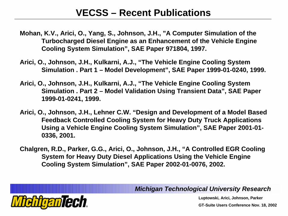
VECSS – Recent Publications
Mohan, K.V., Arici, O., Yang, S., Johnson, J.H., ”A Computer Simulation of the Turbocharged Diesel Engine as an Enhancement of the Vehicle Engine Cooling System Simulation”, SAE Paper 971804, 1997.
Arici, O., Johnson, J.H., Kulkarni, A.J., “The Vehicle Engine Cooling System Simulation . Part 1 – Model Development”, SAE Paper 1999-01-0240, 1999.
Arici, O., Johnson, J.H., Kulkarni, A.J., “The Vehicle Engine Cooling System Simulation . Part 2 – Model Validation Using Transient Data”, SAE Paper 1999-01-0241, 1999.
Arici, O., Johnson, J.H., Lehner C.W. “Design and Development of a Model Based Feedback Controlled Cooling System for Heavy Duty Truck Applications Using a Vehicle Engine Cooling System Simulation”, SAE Paper 2001-01-0336, 2001.
Chalgren, R.D., Parker, G.G., Arici, O., Johnson, J.H., “A Controlled EGR Cooling System for Heavy Duty Diesel Applications Using the Vehicle Engine Cooling System Simulation”, SAE Paper 2002-01-0076, 2002.