vehicle simulation with cylinder deactivation - · pdf filevehicle simulation with cylinder...
TRANSCRIPT
Vehicle simulation with cylinder deactivationPotential analysis of cylinder deactivation using a detailed vehicle model Cyrille Frottier, Lars Böttcher, GT-SUITE Users Conference, October 2011

© IAV · 10/2011 · CF · DA-E4 2
Vehicle simulation with cylinder deactivation
• Table of content
kalle
jipp
/ pho
toca
se.c
om
Motivation
Preliminary study
Detailed vehicle model
Results of the driving cycle
Conclusion
© IAV · 10/2011 · CF · DA-E4 3
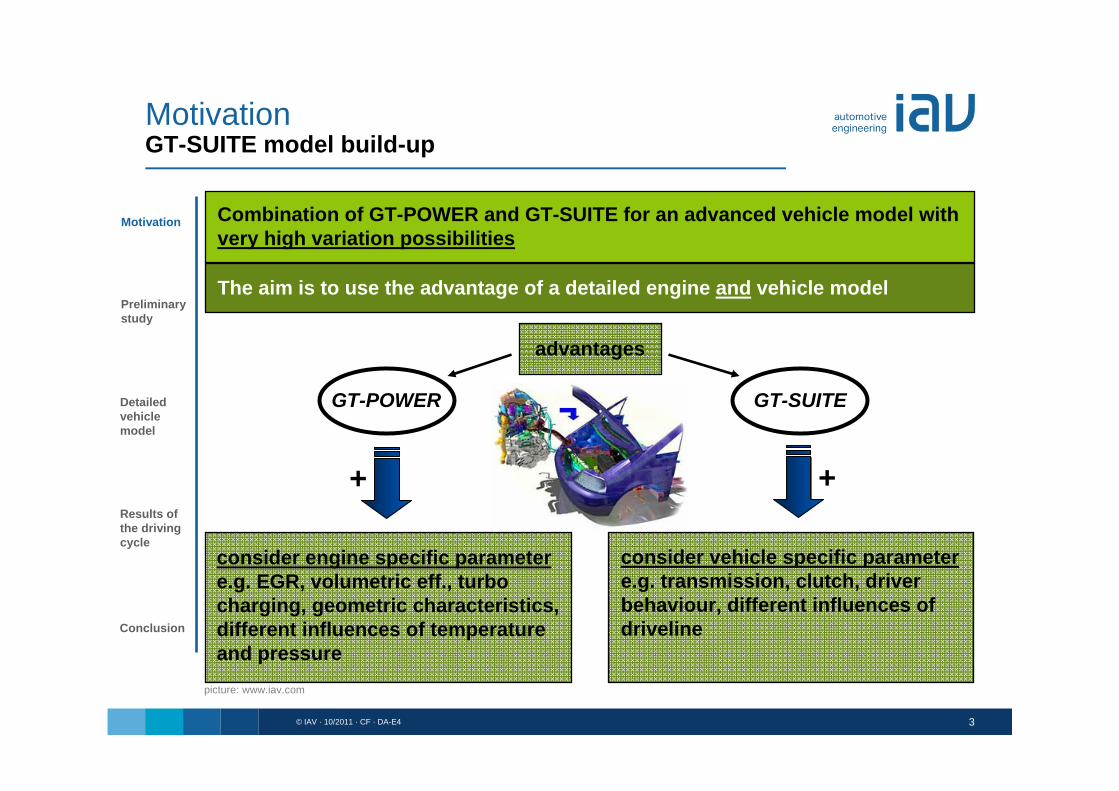
Combination of GT-POWER and GT-SUITE for an advanced vehicle model with very high variation possibilities
The aim is to use the advantage of a detailed engine and vehicle model
GT-POWER GT-SUITE
+
consider engine specific parametere.g. EGR, volumetric eff., turbo charging, geometric characteristics, different influences of temperature and pressure
+
consider vehicle specific parametere.g. transmission, clutch, driver behaviour, different influences of driveline
advantages
Preliminarystudy
Detailedvehiclemodel
Results ofthe drivingcycle
Motivation
Conclusion
picture: www.iav.com
MotivationGT-SUITE model build-up

© IAV · 10/2011 · CF · DA-E4 4
GT-POWER
combination
desired main input is heat release
high variation possibilities of specific vehicle body and engine parameter
interaction between vehicle body and engine
actuation of pedals with a realistic driver
implementation of a ECU to control the different engine features
GT-SUITE
pictures: www.iav.com
MotivationGT-SUITE model build-up
Preliminarystudy
Detailedvehiclemodel
Results ofthe drivingcycle
Motivation
Conclusion
© IAV · 10/2011 · CF · DA-E4 5
MotivationCylinder deactivation
Cylinder deactivation
Fuel consumption benefit
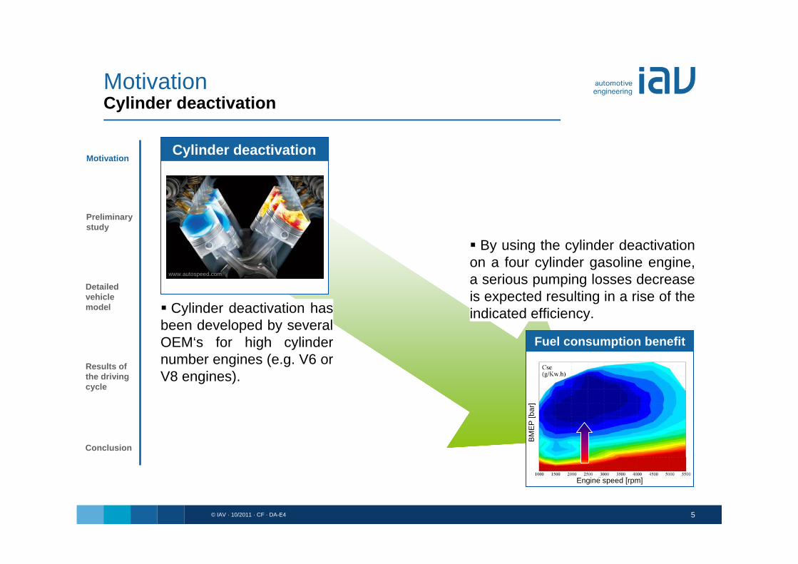
By using the cylinder deactivationon a four cylinder gasoline engine, a serious pumping losses decrease is expected resulting in a rise of the indicated efficiency. Cylinder deactivation has
been developed by severalOEM‘s for high cylindernumber engines (e.g. V6 orV8 engines).
Preliminarystudy
Detailedvehiclemodel
Results ofthe drivingcycle
Motivation
Conclusion
www.autospeed.com
BM
EP
[bar
]
Engine speed [rpm]
© IAV · 10/2011 · CF · DA-E4 6
Preliminarystudy
Detailedvehiclemodel
Results ofthe drivingcycle
Motivation
Conclusion
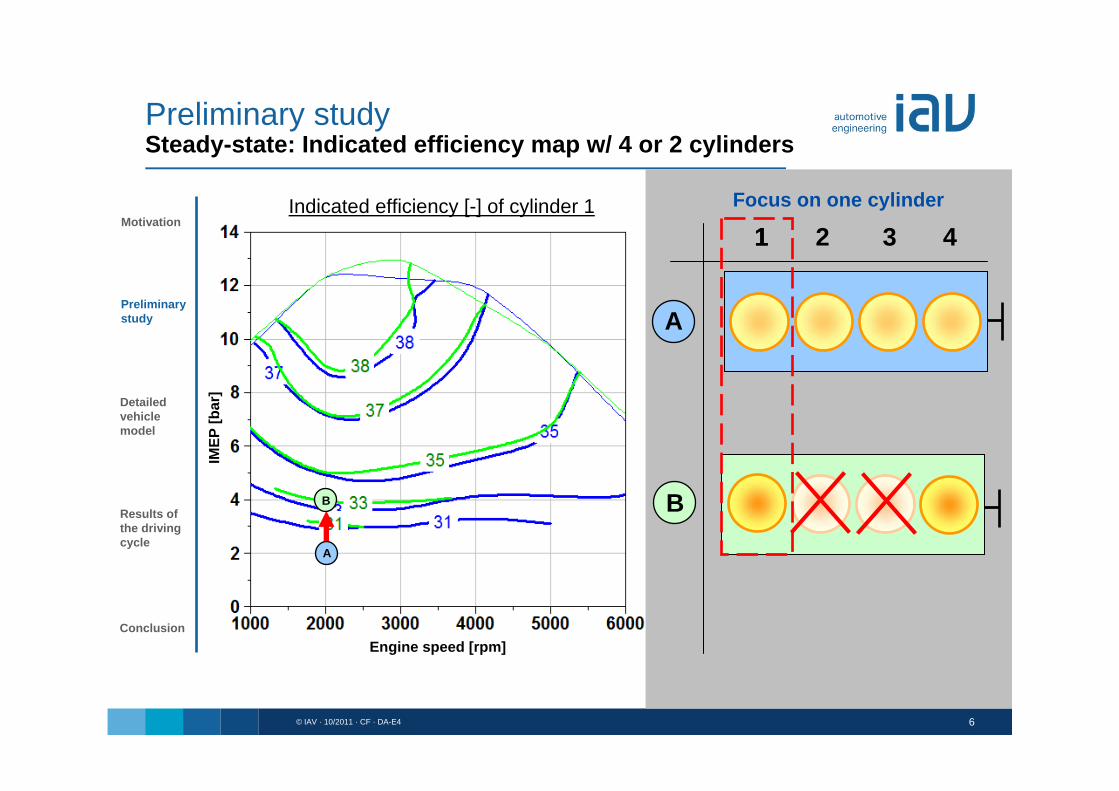
11 2 3 4Indicated efficiency [-] of cylinder 1
Engine speed [rpm]
B
A
A
B
Focus on one cylinder
Preliminary studySteady-state: Indicated efficiency map w/ 4 or 2 cylinders
IMEP
[bar
]

© IAV · 10/2011 · CF · DA-E4 7
Preliminarystudy
Detailedvehiclemodel
Results ofthe drivingcycle
Motivation
Conclusion
i
LPiHPiLPiHPii Q
WW ,,,,
i
HPiHPi Q
W ,,
HPi
LPiLPi W
W
,
,, 1
n M_eff[1/min] [Nm]
2000 25BA
Operating point
29.0,, LPiHPii 34.0,, LPiHPii Torque
With 2 cylinders, a higher IMEP is needed, produced with a higher combustion work (& higher thermal efficiency) which reduces seriously the impact of the pumping losses.
Vcyl/Vmax [-] Vcyl/Vmax [-]
Pcy
l.1 [b
ar]
Pcy
l.1 [b
ar]
IMEPcyl.1 = 2 bar IMEPcyl.1 = 4 bar
Preliminary studySteady-state: Indicated efficiency benefit

© IAV · 10/2011 · CF · DA-E4 8
Preliminarystudy
Detailedvehiclemodel
Results ofthe drivingcycle
Motivation
Conclusion
11 2 3 4
A
Engine speed [rpm]
Effective efficiency [-]
A
Focus during a cycle
Preliminary studySteady-state: Effective efficiency map w/ 4 cylinders
Bre
ak to
rque
[Nm
]

© IAV · 10/2011 · CF · DA-E4 9
Preliminarystudy
Detailedvehiclemodel
Results ofthe drivingcycle
Motivation
Conclusion
Valveclosed
11 2 3 4
B
A
B
A constant mechanical efficiency was held for a first estimation.
Bre
ak to
rque
[Nm
]
Engine speed [rpm]
Effective efficiency [-]
A
Focus during a cycle
Preliminary studySteady-state: Effective efficiency map w/ 4 or 2 cylinders

© IAV · 10/2011 · CF · DA-E4 10
Detailed vehicle model
Preliminarystudy
Detailedvehiclemodel
Results ofthe drivingcycle
Motivation
Conclusion
• design improvements regarding the catalyst heating
• variable valve train variations
• cylinder deactivation strategy
A detailed vehicle model enables to investigate strategies during driving cycles like:
1.6l 4cyl. engine
ECU (includes idle controller)
car and driver
pictures: www.iav.com

© IAV · 10/2011 · CF · DA-E4 11
Preliminarystudy
Detailedvehiclemodel
Results ofthe drivingcycle
Motivation
Conclusion
Car and driver subassembly
Detailed vehicle modelSubassemblies
Vehicle controllers useddepending on the driving phase.

© IAV · 10/2011 · CF · DA-E4 12
Preliminarystudy
Detailedvehiclemodel
Results ofthe drivingcycle
Motivation
Conclusion
Car and driver subassembly
Vehicle controllers useddepending on the driving phase.
Detailed vehicle modelSubassemblies

© IAV · 10/2011 · CF · DA-E4 13
Preliminarystudy
Detailedvehiclemodel
Results ofthe drivingcycle
Motivation
Conclusion
Car and driver subassembly
Detailed vehicle modelSubassemblies
Vehicle controllers useddepending on the driving phase.
© IAV · 10/2011 · CF · DA-E4 14
Preliminarystudy
Detailedvehiclemodel
Results ofthe drivingcycle
Motivation
Conclusion
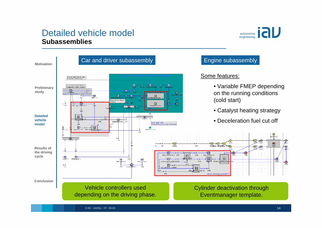
Some features:
• Variable FMEP dependingon the running conditions(cold start)
• Catalyst heating strategy
• Deceleration fuel cut off
Car and driver subassembly Engine subassembly
Detailed vehicle modelSubassemblies
Vehicle controllers useddepending on the driving phase.
Cylinder deactivation throughEventmanager template.

© IAV · 10/2011 · CF · DA-E4 15
Preliminarystudy
Detailedvehiclemodel
Results ofthe drivingcycle
Motivation
Conclusion
Some features:
• Variable FMEP dependingon the running conditions(cold start)
• Catalyst heating strategy
• Deceleration fuel cut off
Car and driver subassembly Engine subassembly
Detailed vehicle modelSubassemblies
Cylinder deactivation throughEventmanager template.
Vehicle controllers useddepending on the driving phase.

© IAV · 10/2011 · CF · DA-E4 16
Detailed vehicle modelDriving phase indicator
Preliminarystudy
Detailedvehiclemodel
Results ofthe drivingcycle
Motivation
Conclusion
ST TD ME
speed target
time delay difference
time
spee
d
Result in an intelligent control with a high flexibility for every cycles
Depending on driving status and tractive resistance,
different proportional and integral gains will be selected dedicated to the controllers
Information about target driving statusAcceleration, Deceleration, Plateau
Vehicle parameter

© IAV · 10/2011 · CF · DA-E4 17
extra urban part
adaptedPreliminary
study
Detailedvehiclemodel
Results ofthe drivingcycle
Motivation
Conclusion
catalyst heating
inner city part – part 1
adapted
Measurements Measurements
Simulation Simulation
Detailed vehicle modelTarget speed vs. simulated speed
Vehi
cle
spee
d [k
m/h
]Ve
hicl
e sp
eed
[km
/h]
Vehi
cle
spee
d [k
m/h
]Ve
hicl
e sp
eed
[km
/h]
Time [sec] Time [sec]
Time [sec] Time [sec]

© IAV · 10/2011 · CF · DA-E4 18
part 1 part 2 part 4
extra urban partinner city part
Results of the driving cycleCylinder deactivation strategy
Preliminarystudy
Detailedvehiclemodel
Results ofthe drivingcycle
Motivation
Conclusion
2 cylinders + boosting or 4 cylinders
part 3
NEDC
4 cylinders
2 cylinders
Veh
icle
spe
ed [k
m/h
]
Time [sec]
© IAV · 10/2011 · CF · DA-E4 19
Results of the driving cycleEUDC driving strategy
Preliminarystudy
Detailedvehiclemodel
Results ofthe drivingcycle
Motivation
Conclusion
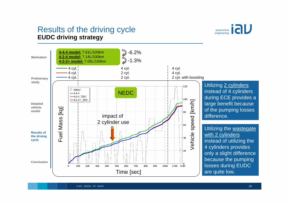
-6.2%-1.3%
NEDC
4 cyl. 4 cyl. 4 cyl.4 cyl. 2 cyl. 4 cyl.4 cyl. 2 cyl. 2 cyl. with boosting
impact of 2 cylinder use
Utilizing 2 cylindersinstead of 4 cylindersduring ECE provides a large benefit becauseof the pumping losses difference.
Utilizing the wastegate with 2 cylindersinstead of utilizing the 4 cylinders provides only a slight differencebecause the pumping losses during EUDC are quite low.
4-4-4 model: 7.61L/100km 4-2-4 model: 7.14L/100km4-2-2+ model: 7.05L/100km
Fuel
Mas
s [k
g]
Veh
icle
spe
ed [k
m/h
]
Time [sec]
© IAV · 10/2011 · CF · DA-E4 20
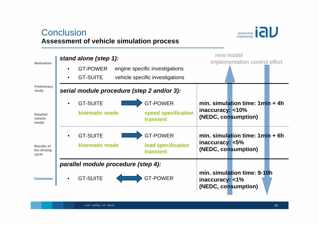
ConclusionAssessment of vehicle simulation process
engine specific investigationsvehicle specific investigations
serial module procedure (step 2 and/or 3):
stand alone (step 1):
parallel module procedure (step 4):
• GT-POWER• GT-SUITE
• GT-SUITE
kinematic mode
GT-POWER
load specification transient
• GT-SUITE
kinematic mode
GT-POWER
speed specification transient
• GT-SUITE GT-POWER
min. simulation time: 1min + 6hinaccuracy: <5% (NEDC, consumption)
min. simulation time: 1min + 4hinaccuracy: <10% (NEDC, consumption)
min. simulation time: 9-10hinaccuracy: <1% (NEDC, consumption)
new model implementation control effort
Preliminarystudy
Detailedvehiclemodel
Results ofthe drivingcycle
Motivation
Conclusion

© IAV · 10/2011 · CF · DA-E4 21
Conclusion
Preliminarystudy
Detailedvehiclemodel
Results ofthe drivingcycle
Motivation
Conclusion
Conclusion
• High flexible model dedicated to engine strategies investigations during drivingcycles
• For instance, the cylinder deactivation technology can be accurately estimated depending on the strategies chosen
• Calculation time of such a model is about 9-10 hours for a NEDC (over night)
Next steps
• Implementation of predictive heat transfer model (instead of maps)
• Implementation of predictive friction model (instead of maps)
• The new technology FRM (keeping the cylinder templates) should be tried out as the first tests from Gamma Technologies are very promising (NEDC < 1 hour)
