vehicular charger - motorola solutions
TRANSCRIPT

VEHICULAR CHARGER(IMPRES Compatible System)TM
User Guide
NNTN7624

blank.fm Page 1 Thursday, October 14, 2010 3:18 PM

En
glish
68009297001-B_Text.fm Page 1 Thursday, December 10, 2015 1:40 PM
SAFETY AND GENERAL INFORMATION
All batteries can cause property damage and/or bodily injury such as burns if a conductive material such as jewelry, keys or beaded chains touches exposed terminals. The material may complete an electrical circuit (short circuit) and become quite hot. Exercise care in handling any charged battery, particularly when placing it inside a pocket, purse or other container with metal objects.
Do not replace or charge batteries in potentially explosive atmosphere. Contact sparking may occur while installing or removing batteries and cause an explosion.
Due to the risk of electrical shock or other physical injury, never insert your hands into the charger pocket.
Product Safety and RF Exposure Compliance
Before using this product, read the operating instructions for safe usage contained in the “Product Safety and RF Exposure Booklet” enclosed with your radio, (Motorola publication number 6881095C98 and 6864117B25) to ensure compliance with RF energy exposure limits.
!W A R N I N G
!
1

En
glis
h
68009297001-B_Text.fm Page 2 Thursday, December 10, 2015 1:40 PM
Operational Warnings
• Vehicles With an Air Bag
Do not place a portable radio or install radio communications equipment in the area over an air bag or in the air bag deployment area. Air bags inflate with great force. If a portable radio is placed in the air bag deployment area and the air bag inflates, the radio may be propelled with great force and cause serious injury to occupants of the vehicle.
• Installation of vehicle communication equipment should be performed by a professional installer/technician qualified in the requirements for such installations. An airbag’s size, shape, and deployment area can vary by vehicle make, model, and front compartment configuration (e.g., bench seat vs. bucket seats).
• Contact the vehicle manufacturer’s corporate headquarters, if necessary, for specific airbag information for the vehicle make, model, and front compartment configuration involved in your communication equipment installation.
• Blasting Caps and Areas
To avoid possible interference with blasting operations, turn your radio off and remove it from the charger when you are near electrical blasting caps, in a blasting area, or in areas posted “Turn off two-way radio.” Obey all signs and instructions.
Operational Cautions
Efficient System Operation
• All equipment must be properly grounded according to Motorola installation instructions for safe operation.
All equipment should be serviced only by an authorized technician.
!W A R N I N G
!
2

En
glish
68009297001-B_Text.fm Page 3 Thursday, December 10, 2015 1:40 PM
About the Vehicular ChargerThe NNTN7624 Vehicular Charger kit is used for charging a radio (or battery alone) when inside a vehicle. The Vehicular Charger kit includes a mounting bracket (to mount the unit inside the vehicle) and wire harness.
The NNTN7624 Tri-Chemistry Vehicular Charger is designed and approved to charge the following batteries for APX7000 series portable radios:
*Note: This battery requires Battery Adapter part number NNTN7688 to engage intothe Vehicular Charger to ensure access for proper charging.
The charger uses a microprocessor to sense the type of battery inserted and control the rate of charge accordingly. A battery will be charged at a rapid rate until it is >90% charged and then it will trickle charge until the battery is >95% charged. The charger will then switch to a maintenance charge mode to keep the battery fully charged.
The charger has IMPRESTM charger to battery communication capability which means it will log charging events and data in the IMPRESTM battery. This charger does not have automated reconditioning as IMPRESTM Desktop Chargers do. Therefore, for an initial calibration (this Vehicular Charger DOES NOT initialize a new IMPRESTM battery) and subsequent recommended recalibration, this unit will indicate when the IMPRESTM battery needs to be taken to an IMPRESTM Desktop Charger for reconditioning/calibration in order to maintain fuel gauge capability on the appropriate radio.
The charger can charge either a battery that is attached to a radio or just the battery alone. This allows a spare battery to be maintained in a fully charged condition.
Kit (PN) Chemistry IMPRES IMPRES 2
NNTN7033 Li-Ion Yes
NNTN7034 Li-Ion Yes
NNTN7035 NiMH Yes
NNTN7036 NiMH Yes
NNTN7037 NiMH Yes
NNTN7038* Li-Ion Yes
NNTN7573 NiMH Yes
NNTN8092 Li-Ion Yes
NNTN8921 Li-Ion Yes
NNTN8930 Li-Ion Yes
PMNN4485 Li-Ion Yes
PMNN4486 Li-Ion Yes
PMNN4487 Li-Ion Yes
PMNN4494 Li-Ion Yes
PMNN4504 Li-Ion Yes
PMNN4505 Li-Ion Yes
3

En
glis
h
68009297001-B_Text.fm Page 4 Thursday, December 10, 2015 1:40 PM
A radio can be operated while in the charger, but this will prolong the amount of time needed to fully charge the battery.
Note: Excessive use of a radio while it is in the charger will cause its battery to become discharged.
The Vehicular Charger has a VRS (Vehicle Repeater System) Toggle Switch which, once enabled, provides an output signal such that when the portable radio is pulled out of the pocket would provide repeater functionality.
4

En
glish
68009297001-B_Text.fm Page 5 Thursday, December 10, 2015 1:40 PM
Getting to Know Your Vehicular ChargerNote: Repeater (VRS) Status LED and Repeater (VRS) Status Toggle are only used
when there is a repeater.
Programming Port - Programming via RLN5671 Field Programmer only by service personnel.
RJ11 - Future Use (Display Module)
Power Connector - Attaches to Power Harness supplied with unit.
Heatsink
Ground Stud - This can be used to tie the Vehicular Charger to the chassis ground.
Charger Status LED
VRS Status LED
VRS Status Toggle - Allows the user to enable the repeater when no radio is present.
5

En
glis
h
68009297001-B_Text.fm Page 6 Thursday, December 10, 2015 1:40 PM
Installation
Mounting hardware supplied includes a trunnion bracket for mounting the unit below the vehicle dashboard, on the floor, or on the wall, and a cable for connection to the vehicle’s electrical system. The bracket enables the charger to be pivoted to a position that offers the best security to the portable radio during rough driving conditions.
Operation Caution
• Ensure the rear of the Vehicular Charger, especially around the heatsink is clear of any obstruction that would otherwise restrict air movement.
• The vehicular charger is designed for 12-volt, negative ground system.
Install the vehicular charger as follows:
1. Plan the location for mounting the charger. Identify the routing paths for the cable and verify that the cable length is adequate. Also check the mounting penetrations required. On most vehicles, it is necessary to penetrate the firewall to reach the battery. Check the opposite side of the firewall for cable clearance before drilling holes. Protect the cable where it passes through the firewall by use of appropriate rubber grommets (not supplied) or other protective measures.
Survey the firewall for existing holes occupied by vehicle wire harnesses. Often there is an opportunity to route other cables using the same path. Because of the wide variation in vehicle design, these instructions may be modified to suit each particular installation.
Guide Pins - help alignment within the U-Bracket or trunnion
Lock - locks the vehicular charger within the U-Bracket (is secured with the use of #10 star washers and thumbscrews.
Strap System secures radio and/or battery in the pocket.
6
En
glish
68009297001-B_Text.fm Page 7 Thursday, December 10, 2015 1:40 PM
A properly installed unit will minimize service calls and equipment downtime. Consider the following guidelines when planning the installation:
• DO consider a mounting location which will allow the unit to be mounted at a 45-degree up angle. This angle provides operational convenience and physical security for the portable radio under rough traveling conditions.
• DO use heat shrink tubing on all splices.
• DO ensure that the cable is not placed under stress, is not exposed to weather, and is not subjected to damage due to engine heat.
• DO retain the in-line cable fuse when trimming the cable to fit. Locate the in-line fuse as close as practical to the supply voltage connection.
• DO check the opposite sides of all mounting surfaces before drilling, to insure that there are no obstructions, such as vehicle wiring and fluid lines.
• DO check to make sure the charger heat sink on the back of the unit has adequate ventilation space when mounted in vehicle.
• DON’T attach the unit to any part of the vehicle that is not rigid or is subject to excessive vibration.
• DON’T install the unit in an area where rain or snow can easily get into it, such as next to a vehicle window which may be left open.
• DON’T install the unit in a location where it could interfere with the vehicle’s operator or operating controls.
• DON’T dress the cable over sharp edges that could cause wear or tearing of cable insulation.
• DON’T install the unit in a location where it may be difficult for the operator to reach.
• DON’T install the unit where it may interfere with the vehicle safety air bag deployment.
• DON’T install the unit where the LED indicators and switch may become physically damaged.
2. Using the trunnion bracket as a template, mark the mounting surface drilling locations. It is recommended that at least four screws be used, with 1/4 inch being the preferred fastener diameter.
3. Re-verify that there are no wires, fluid lines, or other obstructions on the other side of the mounting location, and drill appropriate sized holes for the mounting screws to be used.
4. Referring to Figure 1, mount the bracket using appropriate screws, washers, lock washers, and nuts.
5. Insert the unit into the bracket, and install the washer and threaded knob into the housing, as shown in Figure 1.
6. Rotate the unit to the preplanned mounting angle and tighten the two threaded knobs holding the charger to the bracket.
7

En
glis
h
68009297001-B_Text.fm Page 8 Thursday, December 10, 2015 1:40 PM
7. Referring to Table 1 and Figure 2, connect the red (A+) wire (with the inline fuse) of the supplied cable to either an unswitched terminal on the vehicle’s fuse box or directly to the positive (+) terminal of the vehicle’s battery. Always position the fuse as close to the voltage source as possible.
8. a. Standard wiring to vehicle Switched A+ : Charging OFF with vehicle OFF For installations where the radio may be left in the charger with the vehicle’s ignition switched OFF and minimal vehicle battery current drain is important, the standard wiring connection of the yellow wire to vehicle switched A+ will disable charging. Connect the yellow (ignition sense) wire (with the inline fuse) to a switched terminal on the vehicle’s fuse box. It is important not to connect the yellow wire to the red lead.
Note:The charger will remain ON for approximately 30-minutes after ignition is turned OFF. b. Optional wiring to vehicle A+ : Charging ON with vehicle OFF When the radio is left in the charger for charging with the vehicle’s ignition switched off, the optional wiring connection of the yellow wire to always live vehicle A+ will keep the charger ON. The charger, in this condition will not power down and will continue to drain the vehicle battery.
9. Connect the black (Gnd) wire to any convenient vehicle ground. DO NOT connect the black wire directly to the vehicle battery negative terminal.
10. The white wire is for vehicular repeater operation only. Please refer to installation instructions of the vehicular repeater for instructions on the connection of this wire.
11. Recheck all wiring connections, cable routing, and all physical aspects of the installation. Carefully insert the connector on the end of the cable into the mating connector on the back of the charger and test the charger for proper operation.
Figure 1 .Installing the Vehicular Charger
8

En
glish
68009297001-B_Text.fm Page 9 Thursday, December 10, 2015 1:40 PM
Important Note: If a vehicular repeater is installed, verify operation of the repeater before leaving the vicinity of the vehicle.
Figure 2 Cable Console
Pin Connected To
1 Positive (+) vehicle battery terminal or unswitched fuse terminal2 Repeater (VRS)3 N/C4 Switched fuse terminal (ignition sense)5 N/C6 Vehicle ground
Table 1 Cable Connector Pins
2-AMPINLINE FUSE
OPTIONALCHASSISVEHICLE
BLACK
13.8 VOLTVEHICLEBATTERY
+_
GROMMET
FIREWALL
RED
YELLOW
WHITEREPEATER
BOXFUSE
VEHICULARCHARGER
0.25-AMPINLINE FUSE
OPTIONAL
STANDARD
A+
SWITCHED A+
9
En
glis
h
68009297001-B_Text.fm Page 10 Thursday, December 10, 2015 1:40 PM
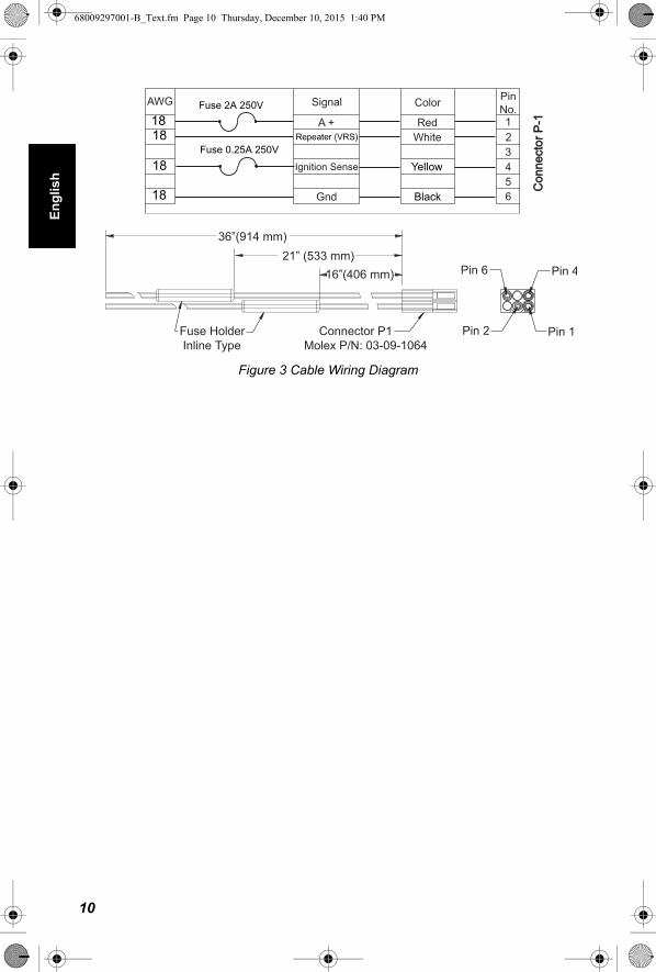
Figure 3 Cable Wiring Diagram
AWG
1820
20
18
Signal
A +PAC - RT
Ignition Sense
Gnd
Color
RedWhite
Yellow
Black
123456
PinNo.Fuse 2A 250V
Fuse .5A 250A
Con
nect
or P
-1C
onne
ctor
P-1
16”(406 mm)
36”(914 mm)
Fuse HolderInline Type
Connector P1Molex P/N: 03-09-1064
Pin 4
Pin 2 Pin 1
Pin 6
MAEPF-27085-O
21” (533 mm)
Fuse 2A 250V
Fuse 0.25A 250V
1818
18
18
Repeater (VRS)
10

En
glish
68009297001-B_Text.fm Page 11 Thursday, December 10, 2015 1:40 PM
Securing the Radio in the Vehicular Charger
The NNTN7616 Vehicular Charger is equipped with a feature that reduces the risk of a portable radio (or battery alone) in the pocket from becoming dislodged and potentially hazardous in the event of a vehicular collision. Operators are instructed to follow the vehicular charger installation instructions and to use this feature as follows:
1. Anyone intending to operate the vehicular charger is advised to locate and become familiar with:
• The Ballistic Nylon Strap. (Tri-Glide adjustment between battery alone or radio with battery attached)
• The Retention Housing (Latch)
• The Engagement Bar (Faceplate).
2. When the vehicular charger is not in use, the latch may be engaged to the Top Engagement Bar on the Faceplate.
3. To use the vehicular charger, disengage the latch from the Top Engagement Bar on the Faceplate.
4. Insert the portable radio or battery alone into the charger pocket. For Non-Display Models, insert the Radio with Battery such that the Main Speaker faces UP; Belt-Clip (if installed) and Battery Contacts face DOWN. For Large Display (Rear) Models, insert the Radio with Battery such that the Main Speaker faces UP; Large LCD Display and Battery Contacts face DOWN. For Battery Alone, contacts face DOWN.
11

En
glis
h
68009297001-B_Text.fm Page 12 Thursday, December 10, 2015 1:40 PM
5. For radios with an antenna installed, loop the strap between the base of the antenna and base of the channel selector, and then engage the latch onto the Top Engagement Bar on the Faceplate. Adjust the strap through the Tri-Glide to secure radio with battery attached within the Vehicular Charger (refer to Figure 4).
Figure 4 . Radio with Battery, Antenna, PSM or RFA Attached
— or —
For radios with a Public Safety Microphone (PSM) and RF Adapter installed, adjust the strap through the Tri-Glide to secure radio with battery attached within the Vehicular Charger (refer to Figure 4).
— or —
For charging a nickel or non-NNTN7038 lithium battery that is not attached to a radio, loop the strap over the top of the battery, then engage the latch onto the Top Engagement Bar on the Faceplate. Adjust the strap through the Tri-Glide to secure battery within Vehicular Charger (refer to Figure 5).
Note: Battery is inserted contacts facing DOWN.
12

En
glish
68009297001-B_Text.fm Page 13 Thursday, December 10, 2015 1:40 PM
Figure 5 .Ni-Battery without Radio
6. For charging lithium battery, NNTN7038, that is not attached to a radio, engage the battery onto the adapter (refer to Figure 6) before inserting into the charger pocket and then loop the strap over the top of the battery adaptor, then engage the latch onto the Top Engagement Bar on the Faceplate (refer to Figure 7).
Note: Battery is inserted contacts facing DOWN.
7. Before you remove a portable radio or battery from the vehicular charger, first disengage the latch from the Top Engagement Bar.
Figure 6. Installation of Li-Ion Battery onto NNTN7688 Adapter
Figure 7. Li-Ion Battery with Adapter
13

En
glish
68009297001-B_Text.fm Page 14 Thursday, December 10, 2015 1:40 PM
Operating the Vehicular Charger
Never place any objects other than a radio and/or battery into the charger pocket — this could damage the charger!
Please avoid contact (direct or incidental) with the heatsink.
Operation of the charger is automatic. When a portable radio or a battery is not in the charger’s pocket, the charger is in standby mode.
Note: Please ensure initial charge of an IMPRESTM battery is performed in an IMPRESTM Desktop Charger to calibrate the battery for optimal performance. IMPRESTM batteries, which are not first calibrated in an IMPRESTM Desktop Charger will not allow the display of fuel gauge on an IMPRESTM radio.
Important Note: Wait until the previous battery LED goes out prior to re-inserting a battery or inserting a new battery into the Vehicular Charger.
To charge a battery, place the radio and battery (or battery alone) into the pocket and push all the way in. While pushing the radio into the pocket, take care not to inadvertently activate the radio’s emergency button.
If a battery alone is placed in the charger, be sure that the contacts are facing DOWN, or, in the case of the NNTN7038 Battery, that the battery is installed onto adapter kit number NNTN7688 prior to engagement into the charger. When the battery is properly seated in the charger pocket, the red LED will light steadily. This indicates that the battery is being charged in the rapid-charge mode.
When the radio/battery are in the charger pocket, fasten the safety strap as shown in Figure 4. If a battery alone is in the pocket, fasten securely as shown in Figure 5 or 7. This will prevent the battery from being shaken out of the charger during rough traveling conditions, and will also prevent it from becoming a dangerous projectile in the event of a vehicle crash.
!W A R N I N G
!
14

En
glis
h
68009297001-B_Text.fm Page 15 Thursday, December 10, 2015 1:40 PM
LED indicators on the front panel of the charger indicate charger status:
Note: Upon a recalibration recommended indication (Alternating Yellow-Green either in the first 4-seconds after initial insertion into the Vehicular Charger or after charge completion), please ensure within the next few charge-cycles or days, that the IMPRESTM battery is charged in an IMPRESTM Desktop Charger to calibrate the battery for maintaining optimal performance. Manual reconditioning may be required when removing a battery indicating Alternating Yellow-Green from the Vehicular Charger and inserting that battery into an IMPRESTM desktop charger within 30 minutes. This is due to an IMPRESTM feature that prevents battery over-charging and cycle life loss. If the above battery is outside of the vehicular charger for more than 30 minutes prior to inserting it into an IMPRESTM desktop charger, automatic reconditioning will occur.
BATTERY CHARGE STATUS INDICATION
LED INDICATOR CHARGE STATUS
BLINKING RED Battery is not chargeable or not making proper contact.
RED Battery is in rapid charge mode or in charge recovery due to low voltage battery.
BLINKING YELLOW Battery is recognized by charger but is waiting to rapid charge. The battery temperature is too low or high to allow rapid charging. When this condition is corrected, the battery will automatically begin rapid charging.
BLINKING GREEN Battery has completed rapid charge (>90% available capacity). Charger is in trickle charge mode.
GREEN Battery has completed charging and is >95% charged. Charger is in maintenance charge mode.
ALTERNATING RED-GREEN
(This Feature applies to IMPRESTM Batteries Only) Battery has completed charging and is fully charged. Battery continues to be usable, but may be nearing the end of it’s rated service life.
ALTERNATING YELLOW-GREEN (during first 4 seconds after insertion and upon charge completion)
(This Feature applies to IMPRESTM Batteries Only) Battery must be reconditioned/recalibrated in an IMPRESTM Desktop Charger. Batteries not calibrated will not display fuel gauge on
IMPRESTM radio.
REPEATER (VRS) STATUS INDICATION
LED INDICATOR CHARGE STATUS
OFF Repeater (VRS) not enabled.
ORANGE Repeater (VRS) enabled.
15

En
glis
h
68009297001-B_Text.fm Page 16 Thursday, December 10, 2015 1:40 PM
Specifications
Warranty Replacement
Motorola, Inc. (“Motorola”) warrants the Vehicular Charger against defects in material and workmanship under normal use and service for a period of one (1) year from shipment. Items will be repaired or replaced free of charge for the full warranty period. Freight charges to and from the place where warranty replacement is provided shall be the Customer’s responsibility.
This warranty does NOT cover defects or damages to the Vehicular Charger resulting from (a) use in a manner other than normal operation as specified in the instruction manual; (b) misuse, accident, or neglect; (c) improper disassembly, testing, operation, maintenance, installation, adjustment, alteration, repair, or any modification by the Customer or any person without prior written consent of Motorola.
Input Voltage: 11-16 Vdc (13.6V Nominal)
Maximum Charge Rate: 1250 mA +/- 15%
Charge Current Accuracy: Output > 400 mA +/- 15% of value Output >= 400 mA +/- 20% of value Output <= 50 mA +/- 20mA
Rapid Charge Cycle: 3 hours typical, depending upon battery type, capacity and state of charge.
Size: 3.7" W x 3.7" H x 5.3" D
Weight: 2.75 Lbs (approx.)
Operating Temperature: +41°F to +113°F (+5°C to +45°C)
Inline Fuses: AGC 2 Amp and AGC 0.25 Amp
Repeater (VRS) Output: Open Circuit - Output Voltage (Vvrs) 7.4 Vtyp @ 13.6 V input
16

blank.fm Page 1 Thursday, October 14, 2010 3:18 PM

m
b Motorola, APX and IMPRES are registered trademarks of Motorola Solutions, Inc.All other product or service names are the property of their respective owners.All Rights Reserved.
68009297001-CA
© 2009 and 2015 by Motorola Solutions Inc.
*68009297001*
68009297001-B_back.fm Page 1 Tuesday, December 8, 2015 10:18 AM