ve.net generator module (vgm) - home - victron energy 1 introduction 1.1 the ve.net generator module...
TRANSCRIPT

-0-
VE.Net Generator Module (VGM)
USER MANUAL INSTALLATION MANUAL

-1-
Copyrights 2007 Victron Energy B.V. All Rights Reserved
This publication or parts thereof, may not be reproduced in any form, by any method, for any purpose. For conditions of use and permission to use this manual for publication in other than the English language, contact Victron Energy B.V. VICTRON ENERGY B.V. MAKES NO WARRANTY, EITHER EXPESSED OR IMPLIED, INCLUDING BUT NOT LIMITED TO ANY IMPLIED WARRANTIES OF MERCHANTABILITY OR FITNESS FOR A PARTICULAR PURPOSE, REGARDING THESE VICTRON ENERGY PRODUCTS AND MAKES SUCH VICTRON ENERGY PRODUCTS AVAILABLE SOLELY ON AN “AS IS” BASIS. IN NO EVENT SHALL VICTRON ENERGY B.V. BE LIABLE TO ANYONE FOR SPECIAL, COLLATERAL, INCIDENTAL, OR CONSEQUENTIAL DAMAGES IN CONNECTION WITH OR ARISING OUT OF PURCHASE OR USE OF THESE VICTRON ENERGY PRODUCTS. THE SOLE AND EXCLUSIVE LIABILITY TO VICTRON ENERGY B.V., REGARDLESS OF THE FORM OF ACTION, SHALL NOT EXCEED THE PURCHASE PRICE OF THE VICTRON ENERGY PRODUCTS DESCRIBED HERE IN. Victron Energy B.V. reserves the right to revise and improve its products as it sees fit. This publication describes the state of this product at the time of its publication and may not reflect the product at all times in the future.

-2-
1 Introduction .......................................................................................................................... 3
1.1 The VE.Net Generator Module (VGM) ........................................................................... 3 1.2 Introduction to VE.Net.................................................................................................... 3
2 Installation of your VGM....................................................................................................... 4 2.1 Wiring – A.C................................................................................................................... 4 2.2 Wiring – D.C. ................................................................................................................. 5
3 Using your VE.Net Generator Module .................................................................................. 6 3.1 Quick status line ............................................................................................................ 6 3.2 Generator control........................................................................................................... 6 3.3 Generator monitoring ..................................................................................................... 7 3.4 Generator logging .......................................................................................................... 8
4 Setup ................................................................................................................................... 9 4.1 Generator alarms........................................................................................................... 9 4.2 Generator setup........................................................................................................... 10
4.2.1 Magnetic pickup calibration .................................................................................... 12 Appendix 1 Wiring diagrams for selected generators ................................................................... 14

-3-
1 Introduction
1.1 The VE.Net Generator Module (VGM)
The VE.Net Generator Module is designed to work in conjunction with the standard control system of your generator to allow networked control and monitoring of the generator. The VGM provides detailed monitoring and control facilities, including an auto-start function which allows you to send a single instruction to start the generator. The VGM will automatically carry out the correct process of pre-heat and cranking in order to start the generator.
1.2 Introduction to VE.Net
VE.Net stands for Victron Energy Network. It allows all VE.Net compatible devices to communicate with each other. This means that the charger for example can get information from the battery monitor to optimize the charge current. It is possible to control and monitor all your VE.Net devices from a single VE.Net compatible control panel. This saves space and allows you to control all your devices from one place. A VE.Net consists of a VE.Net panel (VPN), and one or more other VE.Net devices, such as the VE.Net Tank Sensor or VE.Net Battery Controller.
-4-
2 Installation of your VGM To install your generator module you will need:
• VE.Net Generator Module (supplied)
• A.C. sensor box with 20 amp load shed contactor (supplied)
• 2 meter RJ11 cable (supplied)
• VE.Net panel
• Standard straight UTP cable
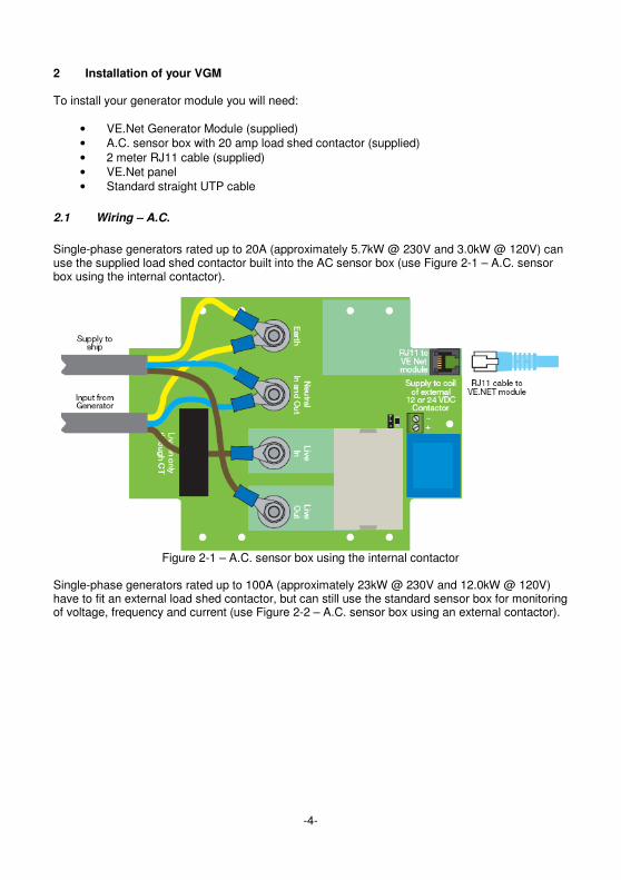
2.1 Wiring – A.C.
Single-phase generators rated up to 20A (approximately 5.7kW @ 230V and 3.0kW @ 120V) can use the supplied load shed contactor built into the AC sensor box (use Figure 2-1 – A.C. sensor box using the internal contactor).
Figure 2-1 – A.C. sensor box using the internal contactor
Single-phase generators rated up to 100A (approximately 23kW @ 230V and 12.0kW @ 120V) have to fit an external load shed contactor, but can still use the standard sensor box for monitoring of voltage, frequency and current (use Figure 2-2 – A.C. sensor box using an external contactor).

-5-
Figure 2-2 – A.C. sensor box using an external contactor
2.2 Wiring – D.C.
The VGM can be powered from either the starter battery or the domestic battery; however it is recommended that the domestic battery be used, as even in standby, the VGM consumes a small amount of power. If the VGM is powered from the starter battery, connect 2 and 3 together. Figure 2-3 shows how to wire the VGM for most generators. More specific wiring diagrams for some generators can be found in Appendix 1. Once the generator has been wired up, connect the VPN with the UTP cable.
Figure 2-3 - D.C. wiring

-6-
Gen Controller
Stopped
3 Using your VE.Net Generator Module The main method of control and configuration for the VGM is provided through the VPN. To switch on the panel, hold “Enter” for 2 seconds. When the panel has started, the list of connected VE.Net devices will be displayed. If there are other VE.Net devices connected, it may be necessary to press “▼” until the VGM is displayed.
3.1 Quick status line
When viewing the VGM entry in the device list, you can also see the quick status line. This line gives you a brief summary of the current generator status. At the quick status line, you can press “Enter” to enter the VGM menu. You can then use the “▼” and “▲” buttons to view the different menu items, and “Enter” to enter sub-menus, and change options. Please refer to the VPN manual for more information on navigating VE.Net menus.
3.2 Generator control
The following procedure is used for starting a generator (note: the exact procedure will vary, depending on the type of generator you are using. For more information, please refer to chapter 4.2 - Generator setup).
1. Close the pre-heat relay 2. Wait for pre-heat to complete 3. Close the start relay 4. Wait for the generator output to stabilise 5. Open the pre-heat relay 6. Open the start relay
When the VGM is instructed to start the generator (either by using the VPN, or pressing the generator start button), it automatically carries out this procedure without requiring any further action from the user. The VGM also carries out two further steps:
7. Wait for the warm-up period 8. Close the load shedding contactor in A.C. sensor box
These final steps allow the generator to reach full speed before the load is connected, and make sure that the load only receives a clean A.C. signal. The procedure for stopping a generator is as follows (note: the exact procedure will vary, depending on the type of generator you are using, for more information, please refer to chapter 4.2 - Generator setup):
1. Open the load shedding contactor in the A.C. sensor box 2. Wait for the cool down period 3. Close the stop relay for one second
When the VGM is instructed to stop the generator (either by using the VPN, or pressing the generator stop button), it automatically carries out this procedure without requiring any further

-7-
action from the user. The purpose of the first two steps, are both to make sure the load only receives a clean AC signal, and to allow the generator to gradually slow down before being stopped. This is particularly important for air-cooled generators.
Gen control menu Menu item Description Range Step
size Default value
Gen control Use this option to perform the displayed action.
“start”, “stop”
N/A Depends on the current generator status
Delayed stop
This option determines how long to wait, after the stop command is issued, before the generator is actually stopped. This can be useful, to allow the generator to run unattended for a period of time. For example to charge batteries, or allow laundry to finish.
0 – 500 minutes
10 minutes
0 minutes
Load shed This option allows the normal behaviour of the load shedding relay to be overridden. This can be useful if it is necessary to bring the generator online before the warm-up period is complete, or to bring the generator offline without stopping it.
“yes”, “no”
N/A Depends on the current generator status
3.3 Generator monitoring
In addition to start and stop control of the generator, the VGM also monitors the generator to make sure that it is operating correctly. The VGM can be configured to generate an alarm if the generator is not operating within desired parameters see chapter (4.1 - Generator alarms). Gen monitoring menu
Menu item Description Units
Session run time
The amount of time that has elapsed since the generator was last started.
Hours and minutes
Coolant temp The temperature of the generator coolant. Note: this facility is not supported by all generators.
Degrees Celsius
Oil pressure The oil pressure of the generator. Note: this facility is not supported by all generators.
Pounds per square inch
AC voltage The A.C. output voltage of the generator. Volts AC amperage The generator load current. Amperes
AC frequency The frequency of the generator output. Hertz
AC kilowatts The current power output of the generator. This is calculated from the voltage and current readings.
Kilowatts
Battery voltage The voltage of the starter battery. Volts Engine speed The generator engine speed. By default, this value is
calculated from the measured A.C. frequency. However, if a magnetic pickup is installed and calibrated, then the pickup will be used for the calculation instead (see chapter 4.2.1 - Magnetic pickup calibration).
Revolutions per minute
Average load The average load on the generator since it was last switched on.
Percent
Current load The current load on the generator. Percent

-8-
Next service due
The time remaining before the generator needs to be serviced.
Hours and minutes
3.4 Generator logging
The generator logging menu records information about the overall usage of the generator. This can be useful for determining the health of the generator.
Gen log menu
Menu item Description Units
Total run time The total amount of time the generator has been running since the VGM was installed.
Hours and minutes
Number of starts
The number of times the generator has been started since the VGM was installed.
None
Average load The average load on the generator since the VGM was installed. Percent Last alarm 1st The last alarm type that occurred. N/A
Last alarm 2nd The second to last alarm type that occurred. N/A
Last alarm 3rd The third from last alarm type that occurred. N/A
Num services The number of services this generator has had during its life. None
Service interval Use this option when the generator is serviced, to reset the service interval and update the number of services.
N/A

-9-
4 Setup The VGM is designed to be highly configurable, in order to meet the requirements for a wide range of applications. The following sections describe the available options and how to use them correctly. In order to access the setup menus, it is necessary to set the VPN access level to “user and install”. Once configuration is complete, it is recommended that the VPN access level be set to “user”. For more information on access levels, refer to the VPN user manual.
4.1 Generator alarms
The VGM can be configured to generate an alarm if a problem occurs with the generator. It is also possible to have the VGM automatically stop the generator when certain faults are detected. The actions available for each individual alarm depend on the parameter being monitored. Table 4-1 describes the available alarm actions.
Description Action taken when alarm condition occurs
pre alarm off None. pre alarm on Alarm sent to VPN and VGM fault light illuminates. pre shutdown on Alarm sent to VPN, VGM fault light illuminated, and generator stopped. alarm disabled None. alarm enabled Alarm sent to VPN and VGM fault light illuminates. shutdown enabled Alarm sent to VPN, VGM fault light illuminates, and the generator stopped.
Table 4-1 - Alarm options Note: Most generators have preset shutdown levels for certain types of fault. The alarms for these faults use the “pre alarm on”, and “pre shutdown on” options. When using these alarms, the alarm thresholds should be configured so that the VGM recognises the alarm conditions before the generator does. This is because many generators will not identify the cause of an automatic shutdown, so by allowing the VGM to detect the fault first, the cause can be determined later by looking at the last alarm properties in the “gen log” menu (see chapter 3.4 - Generator logging). For information on changing the alarm thresholds, refer to chapter 4.2 - Generator setup. Gen alarms menu
Menu item Description Supported options Default value
Oil pressure Generates an alarm if the oil pressure is too low). Note: do not enable this alarm unless an oil pressure sender is connected.
“pre alarm off”, “pre alarm on”, “pre shutdown on”
“pre alarm off”
Coolant temp Generates an alarm if the coolant temperature is too high. Note: do not enable this alarm unless a temperature sender is connected.
“pre alarm off”, “pre alarm on”, “pre shutdown on”
“pre alarm off”
Generator overload Generates an alarm if the generator load
“pre alarm off”, “pre alarm on”
“pre alarm on”

-10-
goes over 100%
Loss of AC power Generates an alarm if the AC voltage drops below the specified value.
“alarm disabled”, “alarm enabled”, “shutdown enabled”
“alarm enabled”
Gen failure Generates an alarm if multiple failures are detected.
”alarm disabled”, “alarm enabled”
“alarm enabled”
Gen underload Generates an alarm if the generator has been running at less than the specified load for more than the specified duration.
“pre alarm off”, “pre alarm on”, “pre shutdown on”
“pre alarm off”
Under speed Generates an alarm if the generator drops below 90% of the nominal engine speed.
“alarm disabled”, “alarm enabled”
“alarm enabled”
Over speed Generates an alarm if the generator rises over 110% of the nominal engine speed.
“pre alarm off”, “pre alarm enabled”, “pre shutdown enabled”
“pre alarm enabled”
Service due 25hr Generates an alarm 25 hours before the next service is due.
“alarm disabled”, “alarm enabled”
“alarm enabled”
4.2 Generator setup
This menu contains all of the generator specific settings. It is important to ensure that these setting reflect the characteristics of the generator. Note: Values for the alarm set-points will only be used if the corresponding alarm is enabled (see chapter 4.1 - Generator alarms) Gen setup menu
Menu item Description Range Step size
Default value
Generator type
The type of generator that is connected. This determines the start up and shutdown procedures. Configurations for other generator types are available on request.
“Northern Lights” (standard), “Northern L AS” (Northern Lights auto start), “Vetus”, “Westerbeke”, “Kohler small”, “Kohler large”, “Mase”, “Fischer Panda”
N/A “Northern Lights”
Gen nom voltage
The nominal A.C. output voltage of the generator.
110V/230V N/A 230V
Gen frequency
The nominal output frequency and engine speed for the
“50Hz – 1500rpm”, “50Hz – 3000rpm”,
N/A “50Hz – 1500rpm”
-11-
generator. “60Hz – 1800rpm”, “60Hz – 3600rpm”
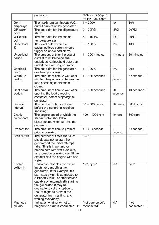
Gen amperage
The maximum continuous A.C. output current of the generator.
1 – 200A 1A 20A
OP alarm point
The set-point for the oil pressure alarm.
0 – 70PSI 1PSI 20PSI
WT alarm point
The set-point for the coolant temperature alarm.
50 – 100°C 1°C 90°C
Underload %
The level below which a sustained load current should trigger an underload alarm.
0 – 100% 1% 40%
Underload period
The amount of time the output current must be below the underload % threshold before an underload alarm is generated.
1 – 200 minutes 1 minute 30 minutes
Overload pre %
The set-point for the generator overload pre alarm
1 – 100% 1% 90%
Warm-up period
The amount of time to wait after starting the generator, before the load shedding contactor is closed.
1 – 100 seconds 1 second
5 seconds
Cool down period
The amount of time to wait after opening the load shedding contactor, before stopping the generator.
9 – 300 seconds 10 seconds
10 seconds
Service interval
The number of hours of use before the generator requires servicing.
50 – 500 hours 10 hours 200 hours
Crank disconnect
The engine speed at which the starter motor should be disconnected when starting the generator.
400 – 1000 rpm 10 rpm 500 rpm
Preheat for The amount of time to preheat prior to cranking.
1 – 60 seconds 1 second
5 seconds
Start retries The number of times the VGM should attempt to start the generator if the initial attempt fails. This is important for marine sets with wet exhausts, as excessive cranking can fill the exhaust and the engine with sea water.
0 – 10 1 3
Enable switch in
Enables or disables the switch inputs for controlling the generator. If for example, the start stop switch is connected to a Phoenix Multi, or other device capable of automatically starting the generator, it may be desirable to set this option to “no” at night, to prevent the generator from starting, and waking everybody.
“no”, “yes” N/A “yes”
Magnetic pickup
Indicates whether or not a magnetic pickup is connected. If
“not connected”, “connected”
N/A “not connected”
-12-
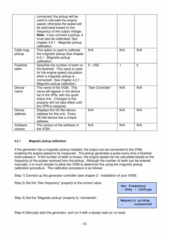
connected, the pickup will be used to calculate the engine speed; otherwise the speed will be estimated based on the frequency of the output voltage. Note: if you connect a pickup, it must also be calibrated. See chapter 4.2.1 - Magnetic pickup calibration.
Calib mag pickup
This option is used to calibrate the magnetic pickup See chapter 4.2.1 - Magnetic pickup calibration.
N/A N/A N/A
Flywheel teeth
Specifies the number of teeth on the flywheel. This value is used for the engine speed calculation when a magnetic pickup is connected. See chapter 4.2.1 - Magnetic pickup calibration.
0 – 250 1 0
Device name
The name of the VGM. This name will appear in the device list of the VPN, with the quick status line. Changes to this property will not take effect until the VPN is restarted.
“Gen Controller” N/A N/A
Device address
Displays the VE.Net device address for this unit. Every VE.Net device has a unique address.
N/A N/A N/A
Software version
The version of the software in the VGM.
N/A N/A N/A
4.2.1 Magnetic pickup calibration
If the generator has a magnetic pickup installed, the output can be connected to the VGM, enabling the engine speed to be measured. The pickup generates a pulse every time a flywheel tooth passes it. If the number of teeth is known, the engine speed can be calculated based on the frequency of the pulses received from the pickup. Although the number of teeth can be entered manually, it is much simpler to allow the VGM to determine this using the magnetic pickup calibration procedure. The calibration procedure is as follows: Step 1) Connect up the generator controller (see chapter 2 - Installation of your VGM). Step 2) Set the “Gen frequency” property to the correct value. Step 3) Set the “Magnetic pickup” property to “connected”. Step 4) Manually start the generator, and run it with a steady load (or no load).
Gen frequency
→ 50Hz – 1500rpm
Magnetic pickup
→ connected

-13-
Step 5) Once the generator is stable go to the “Calib mag pickup” menu and press “Enter”. Step 6) The text on the second line will momentarily read “Calib. Complete”. The calibration procedure is now complete. The number of flywheel teeth detected can be seen in the “Flywheel teeth” property. If there was a problem reading the magnetic pickup during calibration, the “Calib mag pickup” property will momentarily read “Calib. Error!”. Check the magnetic pickup connections and try again.
Calib mag pickup
→ yes
Calib mag pickup
Calib. complete
Flywheel teeth
→ 150
Calib mag pickup
Calib. error!

-14-
Appendix 1 Wiring diagrams for selected generators Fischer Panda

-15-
Masse IS3.5 to IS6.0
-16-
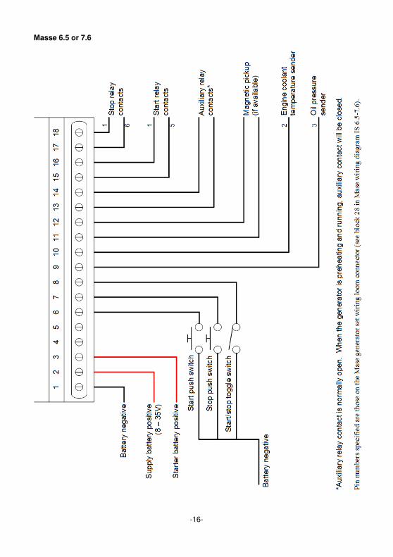
Masse 6.5 or 7.6

-17-
Northern Lights

-18-
Vetus

w w w . v i c t r o n e g e r g y . c o m
Victron Energy B.V. De Paal 35 1351 JG Almere PO Box 50016 1305 AA Almere The Netherlands
Version: 07 Date: 13 December 2007