ventilation fan · ventilation fan warning read and save these instructions installer: leave this...
TRANSCRIPT
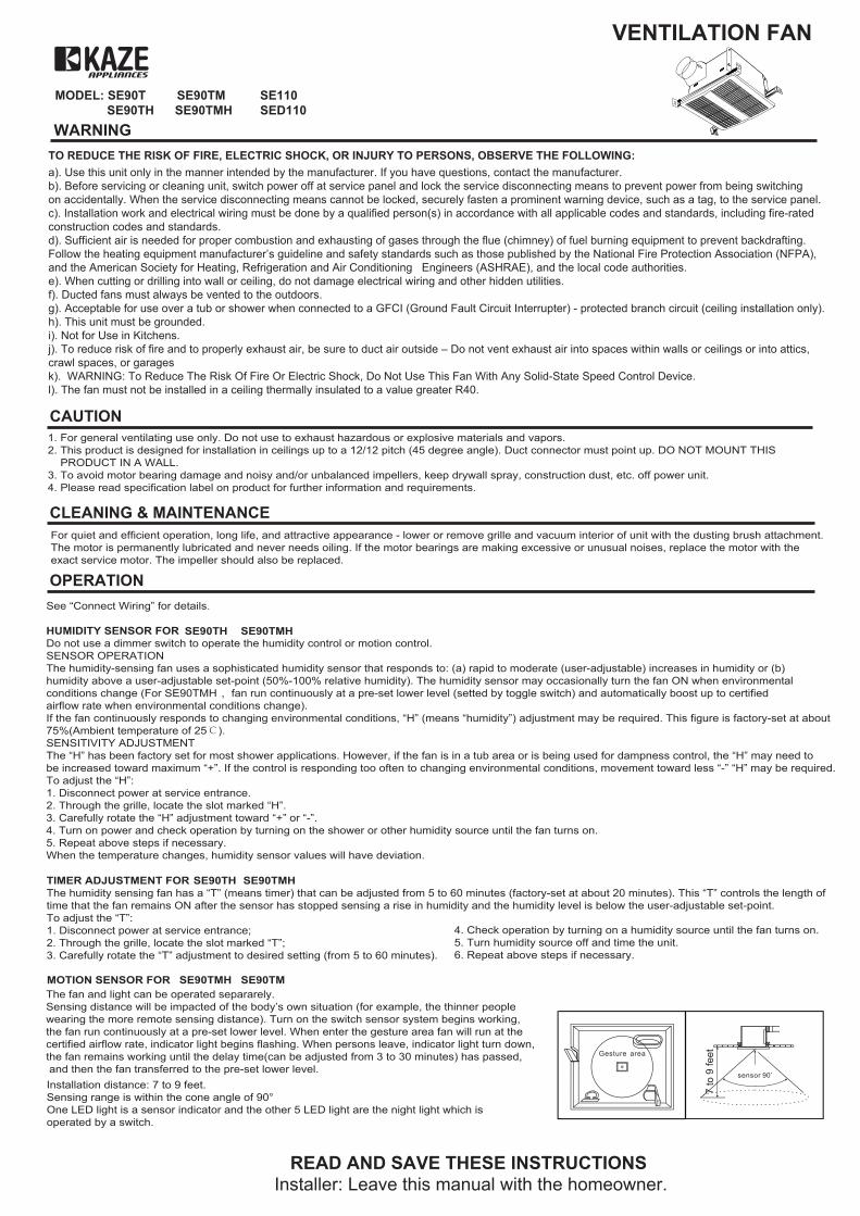
MODEL: SE90T SE90TM SE110 SE90TH SE90TMH SED110
VENTILATION FAN
WARNING
READ AND SAVE THESE INSTRUCTIONSInstaller: Leave this manual with the homeowner.
CAUTION
CLEANING & MAINTENANCE
OPERATION
TO REDUCE THE RISK OF FIRE, ELECTRIC SHOCK, OR INJURY TO PERSONS, OBSERVE THE FOLLOWING:
1. For general ventilating use only. Do not use to exhaust hazardous or explosive materials and vapors.2. This product is designed for installation in ceilings up to a 12/12 pitch (45 degree angle). Duct connector must point up. DO NOT MOUNT THIS PRODUCT IN A WALL.3. To avoid motor bearing damage and noisy and/or unbalanced impellers, keep drywall spray, construction dust, etc. off power unit.4. Please read specification label on product for further information and requirements.
For quiet and efficient operation, long life, and attractive appearance - lower or remove grille and vacuum interior of unit with the dusting brush attachment.The motor is permanently lubricated and never needs oiling. If the motor bearings are making excessive or unusual noises, replace the motor with the exact service motor. The impeller should also be replaced.
a). Use this unit only in the manner intended by the manufacturer. If you have questions, contact the manufacturer.b). Before servicing or cleaning unit, switch power off at service panel and lock the service disconnecting means to prevent power from being switching on accidentally. When the service disconnecting means cannot be locked, securely fasten a prominent warning device, such as a tag, to the service panel. c). Installation work and electrical wiring must be done by a qualified person(s) in accordance with all applicable codes and standards, including fire-rated construction codes and standards. d). Sufficient air is needed for proper combustion and exhausting of gases through the flue (chimney) of fuel burning equipment to prevent backdrafting. Follow the heating equipment manufacturer’s guideline and safety standards such as those published by the National Fire Protection Association (NFPA), and the American Society for Heating, Refrigeration and Air Conditioning Engineers (ASHRAE), and the local code authorities. e). When cutting or drilling into wall or ceiling, do not damage electrical wiring and other hidden utilities. f). Ducted fans must always be vented to the outdoors. g). Acceptable for use over a tub or shower when connected to a GFCI (Ground Fault Circuit Interrupter) - protected branch circuit (ceiling installation only). h). This unit must be grounded. i). Not for Use in Kitchens.j). To reduce risk of fire and to properly exhaust air, be sure to duct air outside – Do not vent exhaust air into spaces within walls or ceilings or into attics, crawl spaces, or garagesk). WARNING: To Reduce The Risk Of Fire Or Electric Shock, Do Not Use This Fan With Any Solid-State Speed Control Device.l). The fan must not be installed in a ceiling thermally insulated to a value greater R40.
7 to
9 fe
et
See “Connect Wiring” for details.
HUMIDITY SENSOR FORDo not use a dimmer switch to operate the humidity control or motion control. SENSOR OPERATIONThe humidity-sensing fan uses a sophisticated humidity sensor that responds to: (a) rapid to moderate (user-adjustable) increases in humidity or (b) humidity above a user-adjustable set-point (50%-100% relative humidity). The humidity sensor may occasionally turn the fan ON when environmental conditions change (For SE90TMH ,fan run continuously at a pre-set lower level (setted by toggle switch) and automatically boost up to certified airflow rate when environmental conditions change). If the fan continuously responds to changing environmental conditions, “H” (means “humidity”) adjustment may be required. This figure is factory-set at about 75%(Ambient temperature of 25℃).SENSITIVITY ADJUSTMENTThe “H” has been factory set for most shower applications. However, if the fan is in a tub area or is being used for dampness control, the “H” may need to be increased toward maximum “+”. If the control is responding too often to changing environmental conditions, movement toward less “-” “H” may be required.To adjust the “H”:1. Disconnect power at service entrance.2. Through the grille, locate the slot marked “H”.3. Carefully rotate the “H” adjustment toward “+” or “-”.4. Turn on power and check operation by turning on the shower or other humidity source until the fan turns on.5. Repeat above steps if necessary.When the temperature changes, humidity sensor values will have deviation.
TIMER ADJUSTMENT FORThe humidity sensing fan has a “T” (means timer) that can be adjusted from 5 to 60 minutes (factory-set at about 20 minutes). This “T” controls the length of time that the fan remains ON after the sensor has stopped sensing a rise in humidity and the humidity level is below the user-adjustable set-point. To adjust the “T”:1. Disconnect power at service entrance;2. Through the grille, locate the slot marked “T”;3. Carefully rotate the “T” adjustment to desired setting (from 5 to 60 minutes).
4. Check operation by turning on a humidity source until the fan turns on.5. Turn humidity source off and time the unit.6. Repeat above steps if necessary.
MOTION SENSOR FOR
SE90TH SE90TMH
SE90TH SE90TMH
SE90TMH SE90TMThe fan and light can be operated separarely.Sensing distance will be impacted of the body’s own situation (for example, the thinner people wearing the more remote sensing distance). Turn on the switch sensor system begins working, the fan run continuously at a pre-set lower level. When enter the gesture area fan will run at the certified airflow rate, indicator light begins flashing. When persons leave, indicator light turn down, the fan remains working until the delay time(can be adjusted from 3 to 30 minutes) has passed, and then the fan transferred to the pre-set lower level.Installation distance: 7 to 9 feet.Sensing range is within the cone angle of 90°One LED light is a sensor indicator and the other 5 LED light are the night light which is operated by a switch.
OPERATION
PLAN THE INSTALLATION
TYPES OF TYPICAL INSTALLATIONS
1. Do not use in a cooking area.2. Two ways to connect ductwork to a factory-shipped unit.
ASSEMBLY INSTRUCTIONS
1. Housing mounted to I-joists (Start at “ASSEMBLY INSTRUCTIONS 1”)2. Housing mounted to joists (Start at “ASSEMBLY INSTRUCTIONS 1” )3. Housing mounted to truss (Start at step “ASSEMBLY INSTRUCTIONS 2”)
2
-+ -+
1 2 3
1 2 3
Toggle switch
Power box
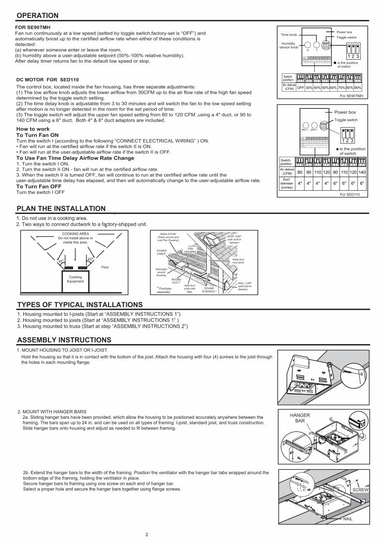
80 90 110 120 90 110 120 140
1 2 31 2 31 2 31 2 31 2 31 2 31 2 31 2 3
6"
Switch position
Duct diameter(inches)
Air deliver(CFM)
6"6"6"4"4"4"4"
80 90 110 120 90 110 120 140
1 2 31 2 31 2 31 2 31 2 31 2 31 2 31 2 3
6"
Switch position
Duct diameter(inches)
Air deliver(CFM)
6"6"6"4"4"4"4"
is the position of switch
DC MOTOR FOR SED110
ROOF CAP*(with built-in
damper)
ROUNDDUCT* WALL CAP*
(with built-indamper)* Purchase
separately
POWERCABLE*
INSULATION*(Place around andover Fan Housing.)
Seal gapsaround
Housing.
FANHOUSING
ROUND ELBOW(S) *
Seal ductjoints with
tape.
Keep ductruns short
Hold the housing so that it is in contact with the bottom of the joist. Attach the housing with four (4) screws to the joist through the holes in each mounting flange.
1. MOUNT HOUSING TO JOIST OR I-JOIST.
HANGERBAR
2. MOUNT WITH HANGER BARS 2a. Sliding hanger bars have been provided, which allow the housing to be positioned accurately anywhere between the framing. The bars span up to 24 in. and can be used on all types of framing: I-joist, standard joist, and truss construction. Slide hanger bars onto housing and adjust as needed to fit between framing.
NAIL
2b. Extend the hanger bars to the width of the framing. Position the ventilator with the hanger bar tabs wrapped around the bottom edge of the framing, holding the ventilator in place. Secure hanger bars to framing using one screw on each end of hanger bar.Select a proper hole and secure the hanger bars together using flange screws. SCREW
FOR SE90TMHFan run continuously at a low speed (setted by toggle switch,factory-set is “OFF”) and automatically boost up to the certified airflow rate when either of these conditions is detected:(a) whenever someone enter or leave the room.(b) humidity above a user-adjustable setpoint (50%-100% relative humidity).After delay timer returns fan to the default low speed or stop.
1 2 3
1 2 3
Toggle switch
Power boxTime knob
Humidity sensor knob
OFF 50%30% 40% 70% 80%60% 90%
1 2 31 2 3 1 2 31 2 31 2 3 1 2 31 2 31 2 3Switch position
Air deliver(CFM)
OFF 50%30% 40% 70% 80%60% 90%
1 2 31 2 3 1 2 31 2 31 2 3 1 2 31 2 31 2 3Switch position
Air deliver(CFM)
is the position of switch
TH
For SE90TMH
For SED110
The control box, located inside the fan housing, has three separate adjustments: (1) The low airflow knob adjusts the lower airflow from 30CFM up to the air flow rate of the high fan speed determined by the toggle switch setting. (2) The time delay knob is adjustable from 3 to 30 minutes and will switch the fan to the low speed setting after motion is no longer detected in the room for the set period of time. (3) The toggle switch will adjust the upper fan speed setting from 80 to 120 CFM ,using a 4" duct, or 90 to 140 CFM using a 6" duct. Both 4" & 6" duct adaptors are included.
How to workTo Turn Fan ONTurn the switch I (according to the following “CONNECT ELECTRICAL WIRING” ) ON.• Fan will run at the certified airflow rate if the switch II is ON.• Fan will run at the user-adjustable airflow rate if the switch II is OFF.To Use Fan Time Delay Airflow Rate Change1. Turn the switch I ON.2. Turn the switch II ON - fan will run at the certified airflow rate.3. When the switch II is turned OFF, fan will continue to run at the certified airflow rate until the user-adjustable time delay has elapsed, and then will automatically change to the user-adjustable airflow rate.To Turn Fan OFFTurn the switch I OFF

4. INSTALL ROUND DUCTWORK Connect the round ductwork (not included) to the damper/duct connector, and run the ductwork to a roof or wall cap (not included). Using tape (not included), secure all the ductwork connections so that they are air tight.
Run 120 V AC house wiring to the location of the fan. Use only UL-approved connectors (not included) to attach the house wiring to the wiring plate. Refer to the wiring diagram, and connect the wires as shown.
ASSEMBLY INSTRUCTIONS
CONNECT ELECTRICAL WIRING
WIRE PANEL
WIRE PANEL
UNIT
BLACK(BLK)
SENSOR
SWITCH BOX
FAN
POWER SUPPLY120V AC
GROUND (GRD)BROWN(BRN)WHITE(WHT)
FAN RECEPTACLE
3
WIRE PANEL UNIT
BLACK (BLK)
SWITCH BOX
FAN
POWER SUPPLY120V AC
GROUND (GRD)WHITE(WHT)
FAN RECEPTACLE
for model SE90TH
for model SE90TM
for model SE90TMH
FAN
SWITCH BOX
FAN
SENSOR
FAN
LIGHT
SWITCH BOX
BLK
WHT
BLK
BLU
WHT
Delay timePreset switch
K
Fan
N
LED
Sensor and LED Light
GRDUNIT
SWITCH
SWITCH
SWITCH
BLKWHTLINE
IN
LED NIGHT
CONTROLCIRCUIT
RED
HUMIDITY
MOTIONUNIT
BLACK(BLK)
SENSOR
LED NIGHTLIGHT
SWITCH BOX
FAN
120V AC LINE IN
GROUND (GRD)REDWHITE(WHT) BLUE(BLU)
FAN RECEPTACLE
MOTION
HUMIDITY
HUMIDITY SENSOR
RECEPTACLE
MOTIONSENSOR
RECEPTACLE
for model SE90T SE110
FAN
DUCT3. ATTACH DAMPER/DUCT CONNECTOR Snap the damper/duct connector onto the fan housing. The connector must be flush with the top of the housing, and the damper flap should fall closed.
FAN
SENSOR
FAN
LIGHT
SWITCH BOX
BLK
WHT
BLK
BLU
WHT
Delay timePreset switch
K
Fan
N
LED
Sensor and LED Light
GRDUNIT
SWITCH
SWITCH
BLKWHTLINE
IN
LED NIGHT
CONTROLCIRCUIT
RED
WIRE PANEL UNIT
BLACK(BLK)
SENSOR
LED NIGHTLIGHT
SWITCH BOX
FAN
120V AC LINE IN
GROUND (GRD)REDWHITE(WHT) BLUE(BLU)
FAN RECEPTACLE
MOTIONSENSOR
RECEPTACLE
This warranty covers all defects in workmanship or materials for: The mechanical and electrical parts contained in this product, for a period of 12 months, from the date of purchase. You must keep and be able to provide your original sales receipt as proof of the date of purchase. This warranty is covered the original retail purchaser of this product. The manufacturer will repair or replace, in your home, any mechanical or electrical part which proves defective in normal household use for a period of 12 months.THIS WARRANTY DOES NOT COVER:• Damages from improper installation• Damages from shipping• Damages from misuse, abuse, accident, alteration, lack of proper care and maintenance• Damages from service by persons other than an authorized dealer or service center.• Labor, service, transportation and shipping charges for the removal of defective parts and for installation of a replacement part, beyond the initial 12-month period.This warranty does not extend to fluorescent lamp starters and tubes.THIS LIMITED WARRANTY IS GIVEN IN LIEU OF ALL OTHER WARRANTIES, EXPRESSED OR IMPLIED, INCLUDING THE WARRANTIES OF MERCHANTABILITY AND FITNESS FOR A PARTICULAR PURPOSE.The remedy provided in this warranty is exclusive and is granted in lieu of all other remedies. This warranty does not cover incidental or consequential damages. Some states do not allow the exclusion of incidental or consequential damages, so this limitation may not apply to you. Some states do not allow limitations on how long an implied warranty lasts, so this limitation may not apply to you. This warranty gives you specific legal rights, and you may also have other rights, which vary from state to state.
Install ceiling material to complete the ceiling construction. Then, cut around the fan housing.First insert the sensor plug into the plug base on the power box, and then install the grille (for model SE90TM and SE90TMH).To attach the grille assembly to the fan housing, pinch the grille springs on the sides of the grille assembly, and position the grille into the housing with the grille springs in the appropriate slots. Push the grille assembly towards the ceiling to secure.
WARRANTY
CONNECT ELECTRICAL WIRING
INSTALL GRILLE
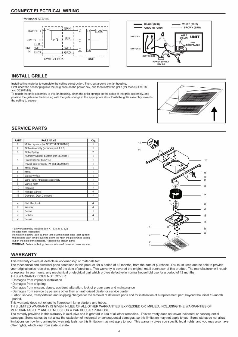
SERVICE PARTS
6
7
d
e
a
12
3
4
5
b
c
8
10
9
11
11
12PART PART NAME Qty.
123
4
56789
101112
abcde
Housing
Damper / Duct Connector
Wiring plate
Screw
Blower WheelWire Panel / Harness Assembly
Motor
11
2
11
111
111141
44141
Isolator
Motor Plate
WasherNut, Hex Lock
Grille Assembly (includes part 1 & 3)Motion system (for SE90TM SE90TMH)
Grille Spring
Hanger Bar Kit
Screw
Humidity Sensor System (for SE90TH )
Power box(for SE90TM and SE90TMH)Power box(for SED110)
* Blower Assembly includes part 7,6, 5, d, c, b, a. Replacement installation:Remove the screw (part c), then take out the motor plate (part 5) from the housing (part 10) by pushing down the rib in the plate while pulling out on the side of the housing. Replace the broken parts.
4
WARNING: Before replacing, be sure to turn off power at power source.
UNIT
BLACK (BLK)
SWITCH BOX
SWITCH I
POWER SUPPLY120V AC
GROUND (GRD)WHITE (WHT)
FAN RECEPTACLE
FANWIRE PANEL
BRN
BLK
SWITCH I
SWITCH II
SWITCH II
BROWN (BRN)
for model SED110