ventura - newcover
TRANSCRIPT

AIRANGER XPL
PROCESS MEASUREMENTS
TEN POINT LEVEL MONITOR
Instruction Manual
PL-336
July 1993
33453360rev 2.0
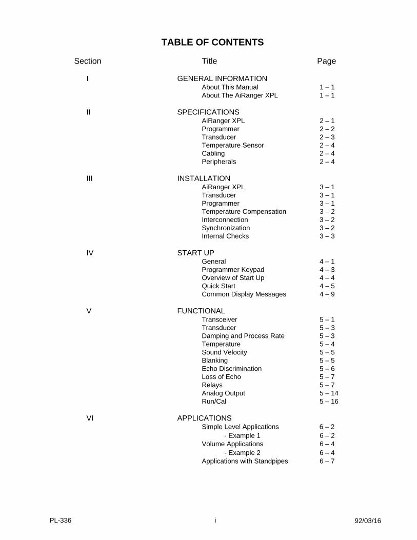
TABLE OF CONTENTS
Section Title Page
I GENERAL INFORMATION About This Manual 1 – 1About The AiRanger XPL 1 – 1
II SPECIFICATIONS
AiRanger XPL 2 – 1Programmer 2 – 2Transducer 2 – 3Temperature Sensor 2 – 4Cabling 2 – 4Peripherals 2 – 4
III INSTALLATION
AiRanger XPL 3 – 1Transducer 3 – 1Programmer 3 – 1Temperature Compensation 3 – 2Interconnection 3 – 2Synchronization 3 – 2Internal Checks 3 – 3
IV START UP
General 4 – 1Programmer Keypad 4 – 3Overview of Start Up 4 – 4Quick Start 4 – 5Common Display Messages 4 – 9
V FUNCTIONAL
Transceiver 5 – 1Transducer 5 – 3Damping and Process Rate 5 – 3Temperature 5 – 4Sound Velocity 5 – 5Blanking 5 – 5Echo Discrimination 5 – 6Loss of Echo 5 – 7Relays 5 – 7Analog Output 5 – 14Run/Cal 5 – 16
VI APPLICATIONS
Simple Level Applications 6 – 2 - Example 1 6 – 2
Volume Applications 6 – 4 - Example 2 6 – 4
Applications with Standpipes 6 – 7
92/03/16PL-336 i

VII PARAMETER DESCRIPTION Security 7 – 1
Start Up 7 – 1Relay Programming 7 – 2Analog Output Programming 7 – 5Volume and Display 7 – 6Environmental and Process 7 – 8Measurement and Simulation 7 – 11Communication and Interconnection 7 – 12Echo Profile Formation 7 – 13Echo Selection and Analysis 7 – 15Time Varying Threshold 7 – 18Test 7 – 19Copy and Reset 7 – 20
VIII TROUBLESHOOTINGGeneral 8 – 1Advanced Calibration 8 – 3Oscilloscope 8 – 4
IX APPENDICES
I Sound Velocities 9 – 1II Glossary 9 – 2III Alphabetical Parameter Listing 9 – 3IV Maintenance And Spare Parts 9 – 4V Communication 9 – 5
X FIGURES
Listing 10 - 1
■
92/03/16PL-336 ii

SECTION I
GENERAL INFORMATION
ABOUT THIS MANUALIMPORTANT
It is essential that this manual be referred to during installation and start up of the AiRanger XPL.
The Quick Start section provides a simplified start up procedure for the AiRanger XPL. It highlights theprogrammer keypad, parameter entry, common display messages and the first eight and most commonly usedparameters; all you need to do to get the AiRanger XPL to give a measurement display.
The Applications section provides a general description of the common applications found in industry andillustrates them with examples. It is suggested that you refer to the sub-section which most suits yourapplication. The calibration may be further optimized by referring to section Parameter Description.
ABOUT THE AIRANGER XPL
The Milltronics AiRanger XPL is a ten point ultrasonic level monitoring system consisting of an AiRanger XPLin a polycarbonate enclosure, a removable programmer and a combination of up to ten ultrasonic transducersof any model. The basic system can be expanded to incorporate relays, analog outputs and computerinterface by the addition of the respective Satellite Alarm Module (SAM-20), Analog Output (AO-10) andBuffered Interface Converter (BIC) peripherals.
The AiRanger XPL emits an ultrasonic signal via the transducer. The echo is reflected from the material andreceived by the transducer. The echo is processed by the AiRanger XPL and the time at which the ultrasonicpulse hits the level or target is extracted and compared to the time at which it was sent. This time differential isthen converted into distance, material level or volume as a basis for display, relay control and analog output.
■
PL-336 1 – 1

SECTION II
SPECIFICATIONS
AIRANGER XPL
Power - 100/115/200/230 V ±15%,jumper selective
- 50/60 Hz, 15 VA
Power fuse - 1/4 amp MDL Slo-Blo or equivalent
Scan points - max. 10 points per AiRanger XPL- frequency independent
Range - max. 60 m (200 ft) under average measurementconditions and dependent upon transducermodel (see Transducers)
Accuracy - 0.25% of range to a max. of 6 mm (0.24")
Resolution - 0.1% of range to a max. of 2 mm (0.08")
Memory - EEPROM (non-volatile)no back-up battery required
Programming - via removable programmer
Displays - 2 Liquid Crystal Displays of4 digits, 18 mm (0.7") high
Operating temperature - -20 to 60 °C(range in which electronics (-5 to 140 °F)will operate within specs, includes temperature rise above ambient due to operation in enclosure)
Ambient temperature - -20 to 50 °C (range outside of (-5 to 122 °F) AiRanger XPL enclosure)
Temperature compensation - 1 common temperature sensorinput, expandable *
- error: - without temperature sensor: 0.17% / °C- with temperature sensor: 0.09%
* optional TIB-10, Temperature Input Boardand Temperature Sensors
PL-336 2 – 1

Outputs: transducer drive - program selective, dependent upon transducer model(s) used
- 44 kHz, 315 V peak pulses of max. 1 mSec duration, typically
- 22 kHz, 150 V peak pulses of max. 1.7 mSec duration, typically
- 13 kHz, 150 V peak pulses of max. 1.7 mSec duration, typically
- max. repetition rate of 200 mSec/transmit
analog - programming only, no on board output- optional AO-10, Analog Output module
(see Peripherals)
alarms - programming only, no on board relays - optional SAM-20, Satellite Alarm Module
(see Peripherals)
communication - transmit only- single ±20 mA bipolar current loop
at 4800 baud rate - maximum loop length 3,000 m (10,000 ft)- loading: max. 3 peripherals (see Peripherals)
Enclosure - CSA enclosure 4 (similar to NEMA 4)- 209 mm W x 285 mm H x 92 mm D
(8.2" W x 11.2" H x 3.6" D)- polycarbonate
Shipping weight - 2.7 kg (6 lb)
Options - TIB-10, Temperature Input Board (mounted in AiRanger XPL)
Peripherals (optional) - AO-10, Analog Output Module - SAM-20, Satellite Alarm Module
PROGRAMMER
Enclosure - general purpose - 67 mm W x 100 mm H x 25 mm D
(2.6" W x 4" H x 1" D)- ABS plastic
Operating temperature - -20 to 50 °C (-5 to 122 °F)
Battery - 9 V (style - ANSI/NEDA 1604)
Shipping weight - 150 g (0.3 lb)
92/10/22PL-336 2 – 2

TRANSDUCERS - 1 per scan point - range is specified for transducers when used with AiRanger XPL
under average measurement conditions
MODEL AMBIENT. TEMP. FREQUENCY RANGE WEIGHT** (Beam Angle) std. cable
ST-25 -40 to 93 °C * 44 KHz 0.3 to 7.5 m 0.9 kg (-40 to 200 °F) (12°) (1 to 25 ft) (2 lb)
ST-50 -40 to 93 °C * 44 KHz 0.3 to 15.2 m 3.9 kg (-40 to 200 °F) (5°) (1 to 50 ft) (8.5 lb)
ST-100 -40 to 77 °C * 22 KHz 0.9 to 30 m 15.8 kg (-40 to 170 °F) (7°) (3 to 100 ft) (35 lb)
LR-21 -40 to 77 °C 22 KHz 0.9 to 30 m 3.9 kg (-40 to 170 °F) (5°) (3 to 100 ft) (8.5 lb)
LR-13 -40 to 77 °C 13 KHz 1.2 to 60 m 7.7 kg(-40 to 170 °F) (5.5°) (4 to 200 ft) (17 lb)
* maximum ambient temperature for polyethylene foam facing is 77 °C (170 °F)
** approximate shipping weight of transducer with standard cable length and unflanged
ST-25 & ST-50 - CPVC housing with polyurethane faceOptional faces:- CPVC: for corrosive applications- Teflon (flange mounted transducers only): for highly corrosive
applications- Polyethylene foam: for dusty, non-condensing applications
- 1" NPT mounting/conduit connection- optional flange mounting, standard sizes:
4", 6", 8" and 12" (metric sizes also available)- totally encapsulated
ST-100 - aluminum housing with polyurethane faceOptional faces:- CPVC: for corrosive applications- Polyethylene foam: for dusty, non-condensing applications
- 1/2" NPT internal thread conduit connection
LR-13 & 21 - aluminum housing with polyethylene and styrofoam face- 1" NPT mounting/conduit connection
Separation - 365 m (1200 ft) from AiRanger XPL under specified conditions(see Cabling)
Approvals - CSA, FM and BASEEFA
PL-336 2 – 3

TEMPERATURE SENSORS (optional)
Resistance - 9.6K ohm (nominal) at 20 °C±5K ohm temperature variance
Separation - 365 m (1200 ft) from AiRanger XPL under specified conditions. Refer to Cabling.
Model TS-2: - range - -40 to 93 °C (-40 to 200 °F)- construction - PVC body
- totally encapsulated- approvals - CSA, FM and BASEEFA- shipping weight - 0.5 kg (1 lb)
LTS-1: - range - -40 to 93 °C (-40 to 200 °F) - construction - 304 stainless steel
- totally encapsulated - for corrosive environments
- approvals - FM and BASEEFA
LTS-1C: - range - -40 to 93 °C (-40 to 200 °F) - construction - 304 stainless steel
- totally encapsulated- for corrosive environments
- approvals - CSA
CABLING (optional)
Transducer - RG-62U coax- must be run separately in grounded
metal conduit
Temperature Sensor - Belden 8760, 1 pair shielded/twisted,18 AWG or equivalent
PERIPHERALS (optional)
AO-10 - Analog Output Module, reference manual PL-337
SAM-20 - Satellite Alarm Module,reference manual PL-338
■
91/03/01PL-336 2 – 4

SECTION III
INSTALLATION
AIRANGER XPL
The AiRanger XPL should be mounted in an area that is: within the ambient temperature range and is suitablefor the specified enclosure. The front cover should be accessible for programming and viewing and havesufficient room to swing open.
It is advisable to keep the AiRanger XPL away from high voltage or current runs, contactors and SCR control drives.
Do not mount the AiRanger XPL in direct sunlightwithout the use of a sun shield
Refer to figure 1 for outline and mounting dimensions.
TRANSDUCERS
Wiring of transducer cable must be done in conjunction with approved conduit, boxes and fittings and to procedures in accordance with all governing regulations.
All transducer cabling must be run in grounded metal conduit for optimum noise immunity.
Refer to: figure 3, ST-25/50 Transducer Outline and Wiring
figure 4, ST-100 Transducer Outline and Wiring
figure 5, LR-21 Transducer Outline and Wiring
figure 6, LR-13 Transducer Outline and Wiring
1. Mount the transducer above the highest anticipated material level
by at least: 30 cm (1 ft) for ST-25 and ST-50 series transducers
90 cm (3 ft) for ST-100 series and LR-21 transducers
120 cm (4 ft) for LR-13
2. Install the transducer so that it will have a clear sound path perpendicular to the liquid surface (refer to figure 8 & 11), or toward the draw point at the bottom of the bin in solids applications (refer to figures 9 & 12).
3. To avoid false echoes, install the transducer such that the sound path will not intersect vessel fillspouts, rough vessel walls, ladders etc. (refer to figures 11 & 12).
PROGRAMMER
In order to calibrate the AiRanger XPL, a programmer (which has a magnetic back plate) must be set into thefront cover recess of the AiRanger XPL. It can be removed when operating in the Run mode. Be sure to keepit away from objects, such as floppy discs, that are susceptible to damage from magnetic fields. (Note: since aprogrammer need not be ordered with each unit, check your order if you think that the programmer is missing).
PL-336 3 – 1

TEMPERATURE COMPENSATION
The AiRanger XPL comes standard with temperature compensation circuitry fed by a compensation signal.This signal is generated internally either by the air temperature parameter (P-35) on a per point basis or byresponse to external air temperature as sensed by a remote temperature sensor.
If a temperature sensor is connected directly to the temperature sensor input, board B\TB1-3/4, it will representa temperature common to all points.
In order to sense the temperature at individual points, an optional Temperature Input Board (TIB-10) must bemounted on board A. Points requiring automatic temperature compensation would have their temperaturesensor connected to the AiRanger XPL via the TIB-10. The TIB-10 comes factory installed on board A or as akit for future customer installation.
TIB-10 INSTALLATION
If the TIB-10 is not installed, the following procedure should be followed.
- insure that the power to the AiRanger XPL has been removed.
- open the front cover of the AiRanger XPL
- mate the TIB-10 RC1 connector to the AiRanger XPL board A RC2 pins
- push TIB-10 down until its standoffs are seated on board A
- insert the three 4-40 x 5/8" screws provided through the TIB-10 mounting holes and standoffs, then screw them into the mating threaded inserts of board A
- note : the terminal block on the TIB-10 is a plug in type. The terminal block can be removed from the connector to facilitate wiring and then plugged back into the connector.
TIB-10
(3) Screws 4-40 x 5/8"
Plug in Terminal Block
RC1Connector
RC2
4-40ThreadedInsert
AiRanger XPLBoard A
90/10/29PL-336 3 – 2

TEMPERATURE SENSOR INSTALLATION
Refer to figure 7.
INTERCONNECTION
All wiring must be done in conjunction with approved conduit, boxes and fittings and to procedures in accordance with all governing regulations.
Refer to figure 13 for wiring of power, communication link, transducer and temperature sensor to the AiRanger XPL.
SYNCHRONIZATION
In applications where the AiRanger XPL is going to be used in a combination of up to 8 AiRanger XPL,AiRanger DPL, MultiRanger Plus and MultiRanger level monitors, sychronization is required. Whensynchronized, no transceiver will transmit within 600 mSec. of another.
The following procedures are required when sychronizing:
XPL DPL Multi Plus MultiRanger
connect XPL board B, board B board B board B board BTB1-1 to: TB1-1 TB1-14 TB1-4 TB1-9
ground ground ground ground ground
on board B cut: N/A N/A J1 J7
set parameter: P-55 = 1 P-35 = 1 N/A N/A
N/A = not applicable
To synchronize the AiRanger XPL with other Milltronics ultrasonic level monitors (e.g. MicroRanger,LiquidRanger, etc. ...), consult with Milltronics or your distributor.
Refer to figure 13 for details on synchronization wiring.
90/10/29PL-336 3 – 3

INTERNAL CHECKS
- temperature sensing: - without TIB-10: if a temperature is not used, a jumper must be installed across board B\TB1-3/4. Refer to figure 13.
- with TIB-10: scan points not requiring a temperature sensor must have the corresponding temperature sensor input on the TIB-10 terminated with a jumper. Refer to figure 13.
- Make sure that voltage stab connector, J1, is properly set for either 100, 115, 200 or 230 V AC operation.
- Power fuse, 1/4 Amp, must be installed.
- Make power connection. Be sure that wires are securely fastened and to proper terminals.
Do not operate with grounding (earthing) disconnected.
■
90/10/29PL-336 3 – 4

SECTION IV
START UP
GENERAL
The AiRanger XPL has two modes of operation: Run and Calibrate. Run is the normal mode of operationwhere readings are displayed and data is transmitted for the control of the alarm module and analog output.The Calibrate mode is used for programming the operational parameters to suit the user’s preferences andthe particular application to which the AiRanger XPL will be applied. It is also used for viewing status anddiagnostic parameters. All access to the AiRanger XPL is done via the programmer when set in the frontcover recess.
After installation procedures have been completed, the AiRanger XPL may be powered up. Upon initialpowering up, that is to say all points are out of service (P-01, points 1 to 10 = OFF), the unit will start up in theCalibrate mode with the following display prompting the user to begin programming.
On subsequent powering up, the unit will start up in Run if at least one point has been placed in service andgive a reading consistent with its programming.
The mode of operation is toggled between Run and Calibrate at the user’s need by pressing .
The first step when calibrating is to reset all parametersto their factory setting by P-99 as described in section VII
When the calibration has been completed, the AiRanger XPL can be made to simulate its operation; givingdisplay, alarms and analog output. Refer to Parameter Description\Simulation and Measurement\P-50/53.
Once satisfied that the parameters have been properly entered, the unit may be put into the Run mode.
Unsatisfactory response in the Run mode, after programming, may indicate that the transducer’s aimingrequires adjustment (especially in solids applications). Refer to figures 8 and 9.
POINT AND PARAMETER SELECTION
90/10/29
RUNCAL
ALTDISPTo directly access a point or a parameter, press until appears in the desired field and then
enter the desired point or parameter number.
are used to scroll up or down through points and parameters. Pressing will alternately
assign the up and down functions to point or parameter selection by displaying in the point orparameter field of the AiRanger XPL display.
and ALTDISP
AiRanger XPL display fields
PL-336 4 – 1

The parameter may be reset to its default value by pressing and the .
PARAMETER SETTING AND VIEWING
Once the desired point and parameter have been obtained, as shown in the left hand fields of the display, thecontents of the parameter for that point will be displayed in the Reading field. The contents may be changedby pressing the required keys so that the Reading field will show the desired parameter value or code. Thedisplay is only entered as the new contents after pressing .
CLR
ENTER
ENTER
PL-336 4 – 2

PROGRAMMER KEYPAD
Key General Function
Calibrate Mode Run Mode
numeric entry
numeric entry
numeric entry
numeric entry
numeric entry
numeric entry display analog output level
numeric entry display temperature in °C (P-35)
numeric entry display material rate of change (P-42)
numeric entry
numeric entry
decimal point entry
negative entry
clear display
completes access into display reading (P-50)
enter Run mode initiates access into Cal mode
press to make a display distance (P-51)
press to index point or press to stop/start scrolling
enters Reading fields press to change point priority status
Cal mode
measurement
as contents ofselected parameter
0
1
2
4
5
6
7
9
8
3
RUNCAL
MEAS
CLR
ENTER
decrements display toshow the precedingpoint or parameter
increments display toshow the next pointor parameter
of the display throughthe points in service
ALTDISP
parameter selection
PL-336 4 – 3

OVERVIEW OF START UP
Outlined below are the progamming steps required to complete the start up, after properinstallation, wiring and powering of your AiRanger XPL
enter the transducer model to set points of measurement in service
select unit of measure preferred for allpoints of measurement
enter distance from transducer face tothe empty level
enter the span of measurement; empty tofill levels
select mode of measurement preferredfor all points of measurement; either the material level or the space between the
transducer face and the material surface
enter, if desired, the analog outputpreferred for all points of measurement
enter alarms if required
repeat this procedure for the other pointsof measurement
These steps are detailed parameter by parameter on the following pages.
LEGENDPress the associated key on programmer :
Display appears for a short time :
Display shown on XPL :
Programmer key : ENTER
PL-336 4 – 4

QUICK START
Apply power to the AiRanger XPLand place the programmer intothe front cover recess.
P - 01 point in service / associated transducer model
0 = off25 = ST-2550 = ST-50100 = ST-10021 = LR-2113 = LR-13
e.g.
P - 02 units of measurement
All entries are made via the programmer keypad. All programmers areinterchangeable, thus any programmer can be used in conjunction with anyAiRanger XPL, AiRanger DPL, MultiRanger Plus or MultiRanger.
NOTE
all points to give reading in % ofspan, programming in centimeters
1 = meters2 = centimeters3 = feet4 = inches* = percent
e.g.
proceed to P-02
wrong transducermodel or faulty wiring;check and continue
if
5 0
parameter 02 global
ENTER
ENTER
2
PL-336 4 – 5

P-03 empty distance to transducer
enter actual distance e.g.
P-04 span
enter required span
e.g.
P-05 mode of measurement
select desired mode
1 = material level2 = space measurement
e.g.
P-06 analog output
select desired option
1 = 0-20 mA2 = 4-20 mA3 = 20-0 mA4 = 20-4 mA
e.g.
to retain 4-20 mAoption, do nothing
factory setting, e.g. : empty distance = 1000 cm
actual empty distance = 800 cm
courtesy setting,e.g. : span = 700 cm
span = 600 cm
mode of measurement forall points = material level
parameter 06 global analogoutput = 4-20 mA
0 08
0 06
parameter 05 global
mode of measurement = space
1
ENTER
ENTER
ENTER
PL-336 4 – 6

P-07 high alarm
enter desired setpoint
e.g.
P-08 low alarm
enter desired setpoint
e.g.
program point 2
bank 1, relay 11 assigned
low alarm ON setpoint = 20% of span
point 1 low alarmON setpoint = 25 % of span
index point field
select point 2
index parameter field
select parameter 01
To copy the programming of a point to another point or sequence of points, use the copy parameter P-99
point 1 high alarmON setpoint = 75% of span
bank 1, relay 1 assigned
high alarm ONsetpoint = 80% of span
setpoint in cm
7 5
ENTER
2 5
ENTER
ALTDISP
0 1
ALTDISP
ALTDISP
0 2
PL-336 4 – 7

when programming is completed
e.g. level of material = 67% of span
RUNCAL
refer to sectionTroubleshooting\General
e.g. after programming point 1
short or open in transducer wiring
✌
if
if
PL-336 4 – 8

COMMON DISPLAY MESSAGES
Reading Field Message Comment
have initiated access into appears after pressing
clear all parameters - P-99 global reset
return to factory setting
change change in factory setting of standard
alarm parameter
overflow reading is larger than display capabilities
factory reset P-99 point reset
loss of echo displayed in Run mode to indicate loss of echo
off point or alarm function out of service
percent appears when calibrating units of measurement
in percent
have entered Run mode appears after pressing
no value contents of parameter empty or no reading display
spare parameter
Calibrate mode
■
RUNCAL
RUNCAL
PL-336 4 – 9

SECTION VFUNCTIONAL
TRANSCEIVER
SCANNING
The AiRanger XPL transceiver transmits the selected combination of long (P-67) and/or short pulses (P-66) inorder to perform a measurement. A short pulse is restricted to short ranges. A short pulse echo is thus definedas an echo from a short pulse. A long pulse covers the full measurement range of the AiRanger XPL. A longpulse echo is defined as an echo from a long pulse. The range specification is as follows:
Neon lamp L1 on the board B will flash for every pulse that is transmitted. The set number of long pulses ofthe combination will be transmitted first. The transmitter pauses while the received echoes are beingprocessed before transmitting the next set of pulses. The scanning relays switch as soon as the last long orshort pulse to the selected point has been transmitted. Processing of the previous pulse series occurs whilethe scanning relays are switching and will not allow the transmitter to operate for the next point until theprocessing of the previous point has been completed. Thus the normal scanning sequence is to cycle throughall in service points, point 1 through 10.
Points are placed in service (P-01) by identifying the model of transducer associated with that point. When thecode is entered, a test pulse is transmitted to verify that the proper code has been entered and the transducermodel is displayed as a proper response. Otherwise, the display will show a message to indicate that it isunsure of the transducer or the integrity of the associated wiring or installation. This may be due a short oropen circuit in the transducer or excessive ringing due to over tightening of the transducer or temperatureextremes.
PRIORITY
If points have been given priority status, either ‘Manual’ or ‘Auto’, then the scanning cycle will proceed on twolevels. All priority points will be sequentially scanned once followed by a scan of the first non-priority point. Allpriority points will be re-scanned and then the second non-priority point will be scanned. Thus a non-prioritypoint will only be scanned once per cycle.
e.g. priority points: 1 & 3 non-priority points: 2, 4 & 5 sequence: 1 3 2 1 3 4 1 3 5 1 3 2
92/03/16
1 cyclepriority points scanned 3 times non-priority points scanned once
Transducer Transition Zone
ST-25 1 m ST-50 1 m ST-100 2 m LR-21 2 m LR-13 3 m
PL-336 5 – 1

MANUAL
Any point or set of points may be given priority status. This is done during the run mode by pressing ENTERwhen the desired point is displayed. A dot will appear in the ‘Status’ field of the point being displayed toindicate priority. Priority status is removed in the same way, as the ENTER key acts as a toggle.
AUTO
Under auto priority scanning, priority is automatically assigned to points meeting the criteria established bysetting parameter P-57. When the criteria for priority is no longer met, then the priority status is automaticallyremoved. The criteria can be any combination of the following conditions :
filling rate : if the filling rate ( P-42 / ) is greater than the filling rate limit, the point concerned is placed on priority.
emptying rate : if the emptying rate (P-42 / ) is greater than the emptying rate limit, the point concerned is placed on priorty.
L.O.E. : if a loss of echo condition occurs, the point concerned is placed on priority.
If more than one point is placed on auto priority, the priority points will be scanned in numerical order.
Auto priority will automatically cancelpoints placed on priority manually.
FREQUENCY
The transceiver section of the AiRanger XPL is located on the board B. As the transceiver operatingfrequency must match the resonant frequency of the transducer being scanned, the transmit signal will begenerated at the corresponding frequency (P-1). The receiver will be tuned, on a per point basis as well, inorder to process the receive echo.
DISPLAY
While in the Run mode, the Reading field will be periodically updated. The default display is a reading ofmeasurement (P-50). The display can be made to show other types of readings by pressing one of the dualfunction keys (refer to section Start Up\Programmer Keypad). The alternate reading will remain displayed untilanother reading is selected.
92/03/16
The display scrolls through the selected reading for the points in service. Pressing will stop/start theautomatic scrolling of the display. When the automatic scrolling is stopped, the display can be manuallyscrolled forward or reverse by pressing or key respectively. Thus the display scrolling is completelyindependent from the transducer scanning.
point 1 given priority status
ALTDISP
7
7
PL-336 5 – 2

TRANSDUCER
The transducer converts the electrical energy of the transmit pulse from the transceiver into acoustical energyand converts the acoustical energy of the echo back into electrical energy for the transceiver receive period.
The effective acoustical energy is generated from the face of the transducer and is radiated outward,decreasing in amplitude at a rate inversely proportional to the square of the distance. Maximum power isradiated axially (perpendicular) from the transducer face in a line referred to as the axis of transmission.Where power is reduced by half (-3 dB), a conical boundary defining the sound beam, centered about the axisof transmission is established. The diametric measurement of the cone in degrees defines the beam angleand varies according to the transducer type. Impedance matching techniques are used to optimize the transferof power from the transducer into air and from the air back into the transducer.
Beam angle, frequency and range are three of the more prominent characteristics of concern when choosing atransducer for an application. The AiRanger XPL is designed to work with any combination of the Milltronicstransducers available by the programming of P-01. Refer to section Specifications\Transducers for detailedspecifications.
DAMPING AND PROCESS RATE
The AiRanger XPL provides damping to control the maximum rate of change of the displayed material level orvolume and of the mA output signal. As most relay functions respond to the dampened level reading, theyindirectly fall under the control of the damping function. Damping may be set within the range of 0.001 to 9999in percent of span per minute. Pressing will momentarily show the damping calculated in linear units per minute.
e.g. if P-02 (units) = 3 (ft) P-04 (span) = 10 and P-40 (fill damping) = 15 (%) of span/min then the maximum fill damping rate is 1.5 ft/min
P-40 is set to provide damping specifically for filling conditions while P-41 is set to provide damping specificallyfor emptying conditions.
The required damping may be estimated by filling and emptying the vessel at its normal rate. The rate ofmaterial level change can be viewed via process rate display parameter, P-42 or by pressing "7" while in theRun mode. The amount of P-40 and P-41 damping should be equal to or greater than the rates of levelchange encountered in P-42. The process rate averaging parameter P- 43 selects the method of averagingused to determine the process rate display, however it has no bearing on the damping function.
Damping is often used to slow down the rate of response of the display especially where liquid surfaces are inagitation or material falls into the sound path during filling.
When in the Calibrate mode, the damping is automatically overridden to give fast response when MEAS ispressed. In the Run mode, the response can be further increased by turning the fuzz filter (P-46) and the echodiscrimination (P-47) OFF - ONLY if they are not required.
If the transducer aiming is being adjusted while in the Run mode, it is suggested that damping be at its factorysetting of 100 to start. The damping can later be changed to suit prevailing conditions.
92/03/16PL-336 5 – 3

Upon a loss of echo condition and after the fail-safe timer (P-45) expires, the display will go to fail-safe high atthe fill damping rate if P-44 = 1 or to fail-safe low at the empty damping rate if P-44 = 2.
TEMPERATURE
In order to compensate for uniform temperature changes of the sound medium over time, temperature sensingshould be used. This will allow the AiRanger XPL to more accurately measure the physical distances whenthe transducer is subjected to temperatures other than 20 °C. The expected error due to temperature changeswill decrease from 0.17% per Celsius degree over the operating range to 0.09%.
The AiRanger XPL is supplied with or without an optional Temperature Input Board (TIB-10).
WITHOUT TIB-10
The AiRanger XPL comes factory set with a jumper across board B terminals TB1- 3/4 to simulate thetemperature programmed into P-35 (factory set for 20 °C, for all points). By removing the jumper and installinga temperature sensor, automatic temperature compensation common to all points is provided (refer to figures3 and 5).
WITH TIB-10
If a Temperature Input Board has been installed, the temperature input sensing terminals on the board B willbe ignored.
The TIB-10 allows the temperature at individual points to be sensed in order to provide automaticcompensation. The TIB-10 comes factory set with jumpers across its 10 point input terminal board, TB1, tosimulate the per point temperature programmed into P-35 (factory set for 20 °C).
A point requiring automatic temperature compensation must have its jumper removed and a temperaturesensor connected. Refer to section Installation\Temperature Sensing.
TEMPERATURE SENSING
A temperature sensor, when used, should be mounted in a location which represents the temperaturefluctuations likely to occur between the transducer and the target. Avoid mounting the temperature in directsunlight as radiant heating can cause a pronounced difference between the air and the transducertemperatures.
Any combination of the three temperature sensor models can be used with the AiRanger XPL. The followinghighlights the more important characteristics which have a bearing on their selection. Refer to sectionSpecifications\Temperature Sensors for detailed specifications.
TS-2: PVC encapsulated, CSA, FM and BASEEFA approval
LTS-1: stainless steel, FM and BASEEFA approval only
LTS-1C: stainless steel , CSA approval only
92/03/16PL-336 5 – 4

If the transducer’s ambient temperature is to remain constant, compensation may be programmed into theAiRanger XPL, instead of using a temperature sensor, by one of following methods.
1. - set jumper across temperature sensing input terminals corresponding to the applicable scan point- select P-35- enter temperature in °C
2. - select P-31- perform an empty calibration
The following temperature functions (in °C) can be viewed :
P-35 air temp. - present temperature at sensor or
- preset temperature, if sensor not used
P-36 max. air temp. - highest temperature encountered during operation
P-37 min. air temp. - lowest temperature encountered during operation
SOUND VELOCITY
The AiRanger XPL can be calibrated to compensate for transducer operation in homogenous vapours withsound velocities other than that of air.
The basis is to physically measure the level (measuring tape or sight glass) and enter this value via P-31. TheAiRanger XPL then calculates the sound velocity by comparing the entered physical measurement to its ownultrasonic measurement (empty calibration, P-31).
P-33, velocity at 20 °C, can be used to enter the known velocity of sound in a particular gas or vapour at 20 °Cor to view the resultant velocity of a sound velocity compensation, normalized to 20 °C.
P-34, velocity at P-35, can be used to enter the known velocity at the temperature of P-35 of sound in aparticular gas or vapour or to view the resultant velocity of a sound velocity compensation, at the temperatureof P- 35.
Refer to Appendix I, for typical sound velocities in various gases and vapours.
BLANKING
Near blanking (P-61) is used to ignore the zone in front of the transducer where ringing or other false echo isat a level that interferes with the processing of the true echo. The minimum near blanking is automaticallygiven a default value when the transducer code is entered (P-01). It can be overridden by entering the desiredamount into P-61. If the code in P-01 is re-entered or changed, the minimum near blanking value will be resetto the default value.
Ringing is the inherent nature of the transducer mass to continue vibrating after the transmit pulse has ceased.The amount of ringing varies with the type of transducer used and decays to acceptable levels in the order ofmilliseconds. Excessive cold and over tightening of the transducer mounting (refer to figure 3) will increase thering time such that it may appear as an echo during the receive cycle. This is usually indicated by an incorrecthigh level reading. This condition may be verified with the use of an oscilloscope (refer to sectionTroubleshooting\Oscilloscope) and may be overcome by increasing the near blanking.
92/03/16PL-336 5 – 5

Far end blanking is a design function that ignores the zone below the zero or empty level where false echoesmay appear at levels that interfere with the processing of the true echo.
In applications where the zero level is above the bottom of the vessel and it is desired to monitor the zonebelow the normal zero, range extension (P-62) may be used to extend the range into the far end blanking.Range extension is entered as a percent of P-03. As range extension reduces the protection afforded by thefar end blanking, it should be used judiciously. Avoid excessive range extension as this may reduce themeasurement’s reliability and accuracy. Range extension is factory set for 20% of P-03. If it is found that falseechoes are appearing ahead of the blanking zone, P-62 should be reduced accordingly.
Blanking is automatically corrected for sound velocity change where temperature and velocity compensationare used; keeping the blanking at the distance at which it was entered.
ECHO DISCRIMINATION
In applications where false echoes are appearing due to agitator blades or transient noise, echo discrimination(P-47) may be used in order to lock onto the true echo. When echo discrimination is turned on, the windowcreated during the processing of the echo is placed around the true echo. The window will not move untilcertain criteria are met. The width of the window (P-48) can be changed to suit the application.
In applications where there is an agitator operating in the vessel, the blades may interfere with level readingswhen the material level is lower than the blades. In such a case, agitator discrimination (P-47=1) can beturned on (factory setting). With the agitator discrimination turned on, the reading will not change unless theecho is ahead of the window (closer) for 5 consecutive measurements or is behind the window (farther) for 2consecutive measurements.
In applications where there is transient noise, acoustical or electrical, signals generated in the transducercircuit or in the transceiver may appear as echoes. In such a case, transient discrimination (P-47=2) can beturned on. With the transient discrimination turned on, the reading will not change unless the echo is outsidethe window (closer or farther) for 5 consecutive measurements.
Echo discrimination, however, slows down the AiRanger XPL’s speed of response. Therefore, if fast responseis required, especially when aiming the transducer while in the run mode, and if there is no agitator or transientechoes involved, the discrimination should be turned off.
Agitator discrimination will not work if the blades are stationary and in the transducer’s beam path.
92/03/16
ringing true echo(level)
false echo
typical receiver signal
end oftransmit
0level
far end blanking
range extension (P-62)as % P-03
empty distance to transducerP-03
P-61 near blanking
range
typical processed signal
PL-336 5 – 6

LOSS OF ECHO
A loss of echo occurs when neither the short or long measurement (P-71) confidence is above the respective
threshold (P-72).
If the loss of echo is due to an open or short in the transducer circuit, the display will immediately flash
The following conditions will apply when the default reading has reached its limit. The relay status applies if
the high and low alarms have not been set beyond 100% and 0% respectively.
FAIL-SAFE MODE RELAY STATUS ANALOG OUTPUT P-44 high alarm low alarm P-06=1 or 2 P-06=3 or 4
fail-safe high on off high low fail-safe low off on low highhold hold hold hold hold
Upon receiving an echo above the threshold and satisfying the echo discrimination (P-47) criteria the loss ofecho condition will be aborted and the reading will move to the present level at the appropriate damping rate.
RELAYS
GENERAL
All alarm relays associated with the AiRanger XPL are located in the optional Satellite Alarm Module, SAM-20,peripheral. The AiRanger XPL itself has no on board alarm relays. The AiRanger XPL serves as the host forprogramming and alarm status display and transmission to the SAM-20.
Each point may be assigned one or more relays and each relay may be assigned one out of six functions.
FUNCTIONS
level : high alarm: alarm ON status occurs when the level rises to the ON setpoint and returns to normal when the level lowers to the OFF setpoint.
low alarm: alarm ON status occurs when the level lowers to the ON setpoint and returns to normal when the level rises to the OFF setpoint.
/ and a default measurement (P-44) in alternating fashion. The default measurement
will be immediately forced to the 0% (fail-safe low) or 100% (fail-safe high) of span level or hold the last
measurement prior to the loss of echo condition.
If the loss fo echo is due to some other reason, the display will hold the last measurement. If the condition
persists for a time beyond the limit as set by the fail-safe timer (P-45), then the display will begin to alternately
flash and a default measurement. The default measurement will be forced to the 0% (fail-safe low)
or 100% (fail-safe high) of span value at the respective fill (P-40) or empty (P-41) damping rate or hold the last
measurement prior to the loss of echo condition.
Pressing will bypass these delays and yield an accurate response immediately. As the defaultmeasurement changes, alarm status and analog output will respond.
92/03/16PL-336 5 – 7

Pressing while programming the alarm function P-13 will cause the left side characters of the Reading field to scroll through the alarm ON status codes :
L - low alarmLL - low low alarmH - high alarmHH - high high alarm
in bounds: alarm ON status occurs when the level is inside the zone between the setpoints and returns to normal when the level goes outside the defined zone.
out of bounds: alarm ON status occurs when the level is outside of the zone between the setpoints and returns to normal when the level goes inside the defined zone.
Pressing while programming the alarm function P-13 will cause the left side characters of the Reading field to scroll through the alarm ON status codes :
b1 - band alarm #1b2 - band alarm #2
rate of change : high alarm: alarm ON status occurs when the process rate (P-42) increases to the ON setpoint and returns to normal when the rate decreases to the OFF setpoint.
low alarm: alarm ON status occurs when the process rate (P-42) decreases to the ON setpoint and returns to normal when the rate increases to the OFF setpoint.
Pressing while programming the alarm function P-13 will cause the left sidecharacter of the Reading field to scroll through the alarm ON status codes:
r1 - rate alarm #1r2 - rate alarm #2
temperature : high alarm: alarm ON status occurs when the sensed temperature (P-35) increases to the ON setpoint and returns to normal when the temperature decreases to theOFF setpoint.
low alarm: alarm ON status occurs when the sensed temperature (P-35) decreases to the ON setpoint and returns to normal when the temperature increases to the OFF setpoint.
loss of echo : alarm ON status occurs under a loss of echo condition.
SETPOINTS
high alarm: the ON setpoint is above the OFF setpoint
low alarm: the OFF setpoint is above the ON setpoint
The ON and OFF setpoints can not be the same on an individual relay but may be common to other relays.The deadband or hysteresis is difference between the ON and OFF setpoints for custom level alarms. Forstandard level alarms, the hysteresis is set at 5% of span from the ON setpoint. For in and out of bounds levelalarms, the hysteresis is set ±2% of span from either boundary.
93/07/07PL-336 5 – 8

The level alarm setpoints are measured from the bottom up, referenced to zero and are programmed as apercent of span, P-04. The rate alarm setpoints are programmed as a percent of span per minute. By pressing while viewing a setpoint parameter, the setpoint in linear units will be momentarily displayed. Refer toexample in Standard or Custom Programming. The temperature alarm setpoints are programmed in degreesCelsius. The loss of echo alarm does not have a setpoint dedicated to its own use, but is controlled by the fail-safe timer, P-45.
RELAY STATUS
During alarm OFF status, the corresponding SAM-20 relays are energized. A relay under alarm ON status willbe de-energized. At this time a status code, if programmed, will be displayed in the ‘Status’ field of the lefthand display and transmitted via the ±20 mA bipolar current loop. Only the alarm ON status code for high, highhigh, low and low low level alarms can be displayed. Alarm ON status data for level and and rate of changealarms is transmitted for customer use via the BIC .
While in the Calibrate mode, alarm relays will hold their prior status, but will respond to measurements taken when is pressed. The alarm ON status however will not be displayed in the status field.
Refer to "Loss of Echo" for relay status during a loss of echo condition.
PROGRAMMING
Alarm programming may be done by one of two methods.
The standard method would be used on tank farms for instance, where the tanks are similar and the alarmsare limited to high and low level programming.
The custom method would be used where the user feels limited by the alarm programming available to himthrough the standard method.
It must be noted that the two methods are interactive; programming a common set of alarms. The lattermethod used to program the relays overrides the settings programmed by the previous method.
The AiRanger XPL may be programmed to control up to 40 relays. The relay set is divided into two banks of20 relays each. The banks are identified as 1 and 2, corresponding to the bank setting on SAM-20 peripherals.The relays are identified as 1 to 20, corresponding to the relay numbers on the SAM-20 peripherals.
STANDARD
Standard programming accesses the relays by point number. Alarm ON setpoints are programmed viaparameters 07, 08, 09 and 10 for high, low, high high and low low alarms respectively.
The ON setpoints may be altered or viewed globally, point 00 or on a per point basis.
The factory setting for the access parameters assigns: - a high alarm at 80% via P-7 to all points, activated- a low alarm at 20% via P-8 to all points, activated- a high high alarm at 90% via P-9 to all points, OFF- a low low alarm at 10% via P-10 to all points, OFF
92/03/16
MEAS
PL-336 5 – 9
Standard programming involves the following two steps:
1. setpoint: on a global or per point basis
- global: - select point 00
- select parameter 07, 08, 09, or 10 e.g.
- per point : - select point e.g.
- select parameter 07, 08, 09 or 10 e.g.
If a relay funtion has been changed via the custom parameter P-13, then CH (changed) or OFF will bedisplayed instead of the setpoints when viewing parameters P-07, P-08, P-09 and P-10.
2. relay assignment
Refer to section, Parameter Description\Relay Parameters\P-11
CUSTOM
Custom programming accesses the relay bank and relay number. Access is gained through parameters (12,13, 14 and 15). It may be done subsequent to the programming of the standard alarm parameters, therebycustomizing these settings or done directly, by-passing the standard parameters. In either case, the customprogramming will override the settings of the standard programming. Thus if it desired to make use of thestandard programming, it should be done prior to the custom programming.
if
disregard Parameter and Readingfields of display
no common reading
high alarm setpoint = 75% of span
setpoint in linear units for 10 m span
point 1 selected, disregard Parameterand Reading fields of display
bank no. 1 relay no. 11selected, ( P-11 = 1 )
low alarm setpoint = 20% of span, P-04
setpoint in linear units for 10m span
92/03/16
7 5
ENTER
PL-336 5 – 10

to select a relay :
first
until ‘_ _’ appears in the Point field
then enter bank number
e.g.
then select relay number
e.g.
Custom programming involves the following three steps:
1. relay : point assignment, P-12
select P-12
to assign all relaysof a bank to the same pointselect bank and relay
e.g.
enter point e.g.
to assign a relay to a pointselect relay and bank
e.g.
disregard point and reading fields ofdisplays, e.g. parameter 12 selected
relay no.2 selected
92/03/16
e.g. parameter 12 selected
bank no. 1 selected
ALTDISP
0 2
1
all relays selected
bank 1 selected
relays assigned to point 2
relay 2 selected
bank 1 selected
2
ENTER
PL-336 5 – 11

enter point
e.g.
to assign a relay to a numberof points in sequenceselect relay and bank
enter limits e.g.
2. relay : function assignment, P-13
select P-13
to assign common function toall relays of a bankselect relay and bank
e.g.
enter function code
e.g.
to assign a function to aspecific relayselect relay and bank
e.g.
relay assigned to point 5
92/03/16
5
1
relay assigned to points 1 through 5
relay 2 selected
bank 1 selected
relay 2 selected
ENTER
5
disregard Point and Readingfields of display
bank 1 selected
bank 1 selected
all relays selected
alarm level function assigned
1
ENTER
ENTER
PL-336 5 – 12

enter function code
e.g.
to assign an alarm status tothe function
3. ON/OFF setpoints, P-14/15
select P-14
to assign a common setpoint toall relays of a bankselect relay and bank
e.g.
enter setpoint e.g.
alarm level function assigned
press until desired
status is displayedpress to enter
displayed status
all relays selected
bank 1 selected
setpoint at 75% of span
e.g. P-14, program ON setpoint
setpoint in linear units for 10 m span
92/03/16
1
ENTER
ENTER
7
ENTER
5
PL-336 5 – 13

to assign a setpoint to aspecific relayselect relay and bank
e.g.
enter setpoint e.g.
repeat for OFF setpoint,
select P-15
SIMULATION
Parameters P-50 through P-53 can be used to simulate alarm conditions while in the Calibrate mode. Whenan alarm condition occurs, the alarm status will be displayed, if programmed, and the corresponding SAM-20relay and status LED will respond. Refer to section Parameter Description\Simulation and Measurement.
If the relay status can affect plant operation or personnel safety, it is advisable to override the relay functions by disconnecting the relay wiring or locking out the power to the associated piece of equipment.
KEEP POWER DISCONNECTEDAT MAIN BREAKER WHEN
AIRANGER XPL COVER IS OPENED
ANALOG OUTPUT
GENERAL
All analog output associated with the AiRanger XPL is located in the optional Analog Output, AO-10,peripheral. The AiRanger XPL itself has no on board analog output. The AiRanger XPL serves as the host forprogramming and analog output display.
Each output may be assigned to any one point or to represent a multipoint average. When assigned to onepoint, the output retains its last updated value to provide a continuous output while other points are beingscanned. When multipoint averaging is selected, the analog output is the average value of the analog outputsof the in service points (P-1) assigned.
The AiRanger XPL can be programmed to provide an analog output (P-06) range of 0 or 4 - 20 mA, and forproportional or inverse span.
relay 2 selected
bank 1 selected
setpoint at 75% of span
92/03/16
7
ENTER
5
PL-336 5 – 14

The analog output responds in the following manner:
The 4 and 20 mA levels can be trimmed slightly via P-16 and P-17 respectively to compensate for any offsetbetween the AiRanger XPL and the customer’s equipment. The 4 and 20 mA levels can also be limited as totheir respective under and over range response via P-18 and P-19
The analog output feature may be turned OFF at the AiRanger XPL by setting P-6 = 0. The AO-10 outputsand alternate displays ( & P-97 ) will immediately drop to 0 mA after a new measurement is processed.The output will remain disabled during simulation ( P-50 to 53 ). However the test routine of P-97 and the trimparameters will remain active. If P-6 ≠ 0, then the analog output will return to its programmed output after anew measurement is processed.
PROGRAMMING
Output programming involves the following four steps :
1. Select span and range via parameters P-04 and P-06 respectively.
2. Output : point assignment, P-16
to select an output
e.g.
enter output
e.g.
enter point assignmentto a specific point
e.g.
OR
92/03/16
analog P-21 = 0 P-21 ≠ 0output P-2 = 1
materialP-2 = 2space
P-2 = 1material
P-2 = 2space
responds to material level material distance material volume ullageif P-6 = 1 or 2,
reads 20 mA whenfull empty full empty
if P-6 = 3 or 4,reads 20 mA when
empty full empty full
until ‘_ _’ appears in the Point field
AO-10 output 2 selected
ALTDISP
0 2
5
ENTER
AO-10 output 2 is assigned to point05
5
PL-336 5 – 15

for multipoint averaging
eg.
3. Trim output levels ( optional ) via parameters P-17 and P-18.
4. Limit output levels ( optional ) via parameters P-19 and P-20.
While in the Calibrate mode, alarm relays will hold their prior status, but will respond to measurements takenwhen is pressed.
SIMULATION
The analog output maybe simulated while in the Calibrate mode by entering parameter P-50 through 53.
If the analog output can affect the plant operation, it may be advisable to override the output duringcalibration or simulation.
KEEP POWER DISCONNECTEDAT MAIN BREAKER WHEN
AIRANGER XPL COVER IS OPENED
Refer to "Loss of Echo" for relay status during loss of echo condition.
RUN/CAL
When the mode of operation is changed from Calibrate to Run, the transceiver resumes its operation. Thereading displayed will be the default reading (P-50) of the measurement taken, either prior to entering or whilein the calibrate mode. The reading will move at a rate controlled principally by the damping (P-40 or P-41) andecho discrimination (P-47). On a multipoint system, it may take a considerable time for the reading to reach thecurrent measurement. Pressing until is shown in the Reading field will force the reading,for thepoint displayed only, to the current measurement immediately. If there are no points in service, the display willshow .
When the mode of operation is changed from Run to Calibrate, the transceiver stops operating. The lastmeasurement is stored and the readings, alarm status and analog output levels are frozen. If is pressed,the AiRanger XPL will react as if it were momentarily placed in the Run mode. Otherwise, it can not respond tochanges in level while in the Calibrate mode. The Point and Parameter fields will display and thus select thelast point and parameter selected prior to the Run mode.
92/03/16
1
ENTER
5 AO-10 output 2 is assigned as amultipoint average of points 1 to 5inclusive
MEAS
■
MEAS
PL-336 5 – 16

SECTION VI
APPLICATIONS
This section highlights the most common applications to which the AiRanger XPL can be applied. Otherapplications not listed here may be akin to those listed or a combination thereof (e.g. monitoring piston positionon a wood pulverizer is in essence a level application).
When calibrating, refer to the application which is most similar to yours. A practical example has been given tofurther illustrate the calibrating features used for an application. In actual practice, however, the example maynot cover all facets of the particular application. Therefore, the user should become familiar with the host ofparameters available. Refer to section Parameter Description
The minimum distance from the transducer face to the target is dependent upon the type oftransducer being used. Minimum blanking should be limited as follows:
ST-25 30 cm (1 ft)ST-50 30 cm (1 ft)ST-100 90 cm (3 ft)LR-21 90 cm (3 ft)LR-13 120 cm (4 ft)
PL-336 6 – 1

SIMPLE LEVEL APPLICATION
The most common application of the Milltronics ultrasonic level measuring systems is for simple levelmonitoring, whereby the material level or space between the transducer and reflecting surface is measuredand displayed. This may or may not include alarms and analog output.
EXAMPLE 1
The application is to obtain level measurements in a 30 ft high vessel and a corresponding 4 - 20 mA output.An LR-21 transducer is installed, its face made level to the top of the vessel designated as point 1. The emptylevel will be at 0 ft (bottom) and the full level will be at 27 ft from the bottom (span). A high alarm is required at4 ft from the top (26 ft from the bottom) and a low alarm is required at 5 ft from the bottom. The maximumfill/empty rate is 1 ft/min. In the event of a loss of echo, the AiRanger XPL is to go into fail-safe hold after 2minutes.
select: point 01perform: P-99
reset all parameters of point 1 to their factory setting
select: P-01enter code "21", LR-21 transducer
advance to: P-02enter option "3", units in feet
P-03enter "30", empty distance to transducer
P-04enter "27", span
P-05enter option "1", material level
P-06 enter option "2", 4 - 20 mA output
P-07 enter "96.29", high alarm ON setpoint
26/27 = 0.9629 x 100%
P-08enter "18.25", low alarm ON setpoint
P-40enter "100", fill damping rate
fill rate of 1 ft/min = 1 ft/27 ft x 100% of span per min = 3.7% of span per min
Typically, the factory set damping of "100" can be used.
P-41enter "100", empty damping rate
empty rate of 1 ft/min = 1 ft/27 ft x 100% of span per min = 3.7% of span per min
Typically, the factory set damping of "100" can be used.
PL-336 6 – 2

P-44enter option "3", fail-safe hold
P-45enter "2", fail-safe timer - 2 min.
all other parameters are left at their factory setting
program the next point then press to enter Run modeRUNCAL
PL-336 6 – 3

VOLUME APPLICATION In addition to simple level applications, volume conversions can be included in the calibration. Volumeconversion should be done on liquid materials only.
Volume conversion is provided for 8 common tank shapes, (P-21). Dimensions are entered using P-04, P-22and P-23. Volume is displayed as 0 - 100% (P-21≠0) and may be converted to volume units by entering aconversion factor into P-24.
Note that P-04, span, must equal 100% (full) level of tank. In many volume applications, the ambient atmosphere is other than air or at a temperature other than 20 °C.Refer to section Functional\Temperature and \Sound Velocity for details on compensating for suchcircumstances.
If it is noted that the AiRanger XPL reading is consistently off by a constant amount as compared to thephysical measurement, this may be compensated for by the measurement offset parameter (P-32).Measurement offset might occur when P-03 or P-04 do not exactly match the tank dimensions referenced forvolume conversion. If the cause of the offset appears below the relay setpoints, the setpoint parameters mayneed to be reset as these will have shifted accordingly.
Refer to figure 11.
EXAMPLE 2
The application is to measure the volume of glue in a horizontal tank with parabolic ends. The tank has beendesignated as point 1 and has been fitted with an ST-25 flanged transducer. The tank manufacturer‘sspecifications state that the total volume is 50 cubic meters.
The maximum fill/draw rate is 0.35 m3/min. In the event of a loss of echo, the AiRanger XPL is to go intofail-safe high after 30 sec.
NOTE : As the glue gives off formaldehyde vapour, a velocity compensation will be required.
transducer
standpipe
90/10/29
L =0. 5 m
A = 1 m
0.5 m3 m = span, P-04(must equal height of tank)
L = 5 m
PL-336 6 – 4

select : point 01perform: P-99 reset all parameters to their factory setting
select: P-01enter code "25", ST-25 transducer
advance to: P-02enter option "1", units in meters
P-03enter "3.5", empty distance to transducer
P-04enter "3", span (inside diameter of tank)
P-05enter option "1", material level
P-21enter option "7", tank shape for volumetric conversion
P-22enter "1", tank dimension A
P-23enter "5", tank dimension L
P-24enter ".5", convert display (x 0.5)
when volume conversion is being used, the display will automaticallyshow the levels in %. As 100% full = 50 cubic meters, a conversion factor of .5 must be entered.
actual volume = conversion factorpercentage
NOTE : As steps P-30 and P-31 involve physical level measurements, for convenience sake, P-31 can bedone before P-30.
P-32 (optional)record present offset for reference
P-30 (optional)perform a full calibration, refer to section Parameter Description\Volume and Display
Parameters\P-30
P-33record present sound velocity for reference
P-31perform an empty calibration, refer to section Parameter Description\Volume and DisplayParameters\P-31
PL-336 6 – 5

P-40/41enter "100", fill/empty damping
at a fill/empty rate of 0.35 m3/min, it will take 50 m3
0.35 m3/minto fill or empty the tank.
The linear fill/empty damping rate =
= 21% of span per min
However, because of the tank’s shape, the top and bottom levels willfill and empty faster than the middle section. Therefore the actual damping value should be greater than that calculated. Typically, the factory set damping of "100" can be used.
P-44enter option "1", fail-safe high
P-45enter ".5", fail-safe timer, 30 sec.
all other parameters are left at their factory setting
program the next point then press to enter Run mode
= 143 min
x 100%3 m of span143 min
RUNCAL
PL-336 6 – 6

APPLICATIONS WITH STANDPIPE
In many solids and liquid applications, access to the vessel must be made via a standpipe. In such cases,Milltronics can provide flange mounted ST-series transducers that will readily mate to the flanged standpipe(refer to figure 11). Another option is to hang the transducer from a blind flange.
The standpipe length should be as short and the diameter as large as possible. As a rule of thumb, the -3 dBcone of the sound beam should not intersect the standpipe wall in applications opening into a vessel.Otherwise, additional near blanking (P-61) will be required to compensate for the interference zone created bythe opening. The rise to run ratio (beam angle)* of the cone can be estimated as follows:
TRANSDUCER RISE : RUN
ST-25 10 : 1 ST-50 20 : 1 ST-100 15 : 1 LR-21 20 : 1 LR-13 20 : 1
transducerradiatingsurface
nointersection
transducerradiatingsurface
sound beamintersectspipewall
reflection atinterference zonecreated by opening
vessel
vessel
near blanking extension of 150mm (6")past end of standpipe may be required
novessel
no additionalblanking required
no additionalblanking required
* refer to figure 11■
PL-336 6 – 7

SECTION VII
PARAMETER DESCRIPTION
NOTE: - (F) indicates P-99 parameter factory setting, where applicable. For reference only - factory setvalues may change with software revisions.
- (G) indicates a global parameter, i.e. parameter contents and calibration is common to all points - (V) indicates parameter can be viewed only, not entered
SECURITY
P-00 security
this parameter can be used to secure the content of parameters P-01 through P-99 so that theycan not be changed. This however does not prevent the parameters from being selected andviewed.
Security is ON if the content of P-00 is any value other than 1954. P-00 can only be directaccessed.
enter: 1954 = security OFF 1954 = security ON
START UP
P-01 point in service
this parameter is used to select points which will be placed into active service and thereby limitthe scanning to these points only. When entered, this parameter will automatically set default values for parameters 04, 43, 48, 61, 65, 67, 68 and 69.Refer to section Functional\Transducer\Scanning
enter: 0
25
50
100
21
13
P-02 units of calibration and display (G)
entering this parameter will set the associated units for parameters03, 04, 22, 23, 25, 26, 30, 31, 32, 33, 34, 40, 41, 50, 51 and 52.
ST-100 series transducer in service
ST-50 series transducer in service
ST-25 series transducer in service
LR-13 series transducer in service
LR-21 series transducer in service
out of service
PL-336 7 – 1

enter 1 = meter (F) 1 * = calibrate in meters, display in %2 = centimeter 2 * = calibrate in centimeters, display in %3 = feet 3 * = calibrate in feet, display in %4 = inches 4 * = calibrate in inches, display in %
NOTE: For % display, entry must be made as " # * " and will be displayed as ‘P # ‘.
P-03 empty distance to transducer
entering this parameter will automatically set a courtesy span value into parameter, P-04
enter distance. (F=10.00)
P-04 span
distance from empty (0%) to full (100%) level. A courtesy span is automatically entered when P-03 is entered.
Courtesy span = P-03 - blanking 1.1
ORenter desired amount
P-05 mode of measurement (G)
enter 1 = material level 2 = space measurement (F)
P-06 milliamp output (G)
enter 0 = OFF1 = 0 to 20 mA2 = 4 to 20 mA (F)3 = 20 to 0 mA4 = 20 to 4 mA
RELAY PROGRAMMING
Refer to section Functional\Relays.
P-07 high alarm setpoint
enter ON setpoint in percent of span. (F= 80.00)
P-08 low alarm setpoint
enter ON setpoint in percent of span. (F= 20.00)
P-09 high high alarm setpoint
enter ON setpoint in percent of span. (F= 90.00)
P-10 low low alarm setpoint
enter ON setpoint in percent of span. (F= 10.00)
91/03/12PL-336 7 – 2

P-11 standard alarm allocation (G)
this parameter is used to assign standard alarm functions to the SAM-20 relays. Three configurations are offered:
enter: 1 = (F)
SAM-20/bank 1 SAM-20/bank 2
pt. 1 H 1 11 L pt. 1 pt. 1 HH 1 11 LL pt. 1pt. 2 H 2 12 L pt. 2 pt. 2 HH 2 12 LL pt. 2pt. 3 H 3 13 L pt. 3 pt. 3 HH 3 13 LL pt. 3pt. 4 H 4 14 L pt. 4 pt. 4 HH 4 14 LL pt. 4pt. 5 H 5 15 L pt. 5 pt. 5 HH 5 15 LL pt. 5pt. 6 H 6 16 L pt. 6 pt. 6 HH 6 16 LL pt. 6pt. 7 H 7 17 L pt. 7 pt. 7 HH 7 17 LL pt. 7pt. 8 H 8 18 L pt. 8 pt. 8 HH 8 18 LL pt. 8pt. 9 H 9 19 L pt. 9 pt. 9 HH 9 19 LL pt. 9pt.10 H 10 20 L pt.10 pt.10 HH 10 20 LL pt.10
2 = SAM-20/bank 1 SAM-20/bank 2
pt. 1 H 1 11 HH pt. 1 pt. 1 L 1 11 LL pt. 1pt. 2 H 2 12 HH pt. 2 pt. 2 L 2 12 LL pt. 2pt. 3 H 3 13 HH pt. 3 pt. 3 L 3 13 LL pt. 3pt. 4 H 4 14 HH pt. 4 pt. 4 L 4 14 LL pt. 4pt. 5 H 5 15 HH pt. 5 pt. 5 L 5 15 LL pt. 5pt. 6 H 6 16 HH pt. 6 pt. 6 L 6 16 LL pt. 6pt. 7 H 7 17 HH pt. 7 pt. 7 L 7 17 LL pt. 7pt. 8 H 8 18 HH pt. 8 pt. 8 L 8 18 LL pt. 8pt. 9 H 9 19 HH pt. 9 pt. 9 L 9 19 LL pt. 9pt.10 H 10 20 HH pt.10 pt.10 L 10 20 LL pt.10
3 = SAM-20/bank 1 SAM-20/bank 2
pt. 1 H 1 11 HH pt. 1 pt. 6 H 1 11 HH pt. 6pt. 2 H 2 12 HH pt. 2 pt. 7 H 2 12 HH pt. 7pt. 3 H 3 13 HH pt. 3 pt. 8 H 3 13 HH pt. 8pt. 4 H 4 14 HH pt. 4 pt. 9 H 4 14 HH pt. 9pt. 5 H 5 15 HH pt. 5 pt.10 H 5 15 HH pt.10pt. 1 L 6 16 LL pt. 1 pt. 6 L 6 16 LL pt. 6pt. 2 L 7 17 LL pt. 2 pt. 7 L 7 17 LL pt. 7pt. 3 L 8 18 LL pt. 3 pt. 8 L 8 18 LL pt. 8pt. 4 L 9 19 LL pt. 4 pt. 9 L 9 19 LL pt. 9pt. 5 L 10 20 LL pt. 5 pt.10 L 10 20 LL pt.10
relays
relays
relays
relays
relays
relays
PL-336 7 – 3

P-12 custom alarm relay:point assignment
this parameter is used to assign one or more points to the SAM-20 relay selected
enter assignment
P-13 custom alarm function
this parameter is used to assign a relay function to the SAM-20 relay selected
enter function code: 0 = off1 = level2 = in bounds3 = out of bounds4 = rate of change5 = temperature6 = loss of echo
optional alarm status: - press
- press
P-14 custom alarm ON setpoints
enter ON setpoint in the following units:
alarm function P-13 units
level alarm 1, 2 or 3 percent of spanrate of change 4 percent of span per minutetemperature 5 degrees Celsius
P-15 custom alarm OFF setpoints
enter OFF setpoint in the following units:
alarm function P-13 units
level alarm 1, 2 or 3 percent of spanrate of change 4 percent of span per minutetemperature 5 degrees Celsius
to enter displayed status identification
93/07/07
to scroll through the alarm ON status identifications after selecting function code:
Function Status StatusCode Identification
1 LL low-low alarmL low alarmH high alarm
HH high-high alarm2, 3 b1 bound alarm #1
b2 bound alarm #24 r1 rate alarm #1
r2 rate alarm #2
ENTER
PL-336 7 – 4

ANALOG OUTPUT PROGRAMMING
Refer to section Functional\Analog Output.
P-16 analog output:point assignment
this parameter is used to assign one or more points to the AO-10 output selected. This parameter is factory set such that the analog output number is assign to the corresponding point number.
enter assignment
P-17 trim for 4 mA
when this parameter is initially selected, the mA output goes to 4 mA.The Reading field however, will display a typical value of 100. The value can be increased or decreased by pressing or respectively or by entering a value. This will proportionally
e.g.:
P-18 trim for 20 mA
when this parameter is initially selected, the mA output goes to 20 mA.The Reading field, however, will display a typical value of 100. The value can be increased or decreased by pressing or respectively or by entering a value. This will proportionally
e.g.:
P-19 limit for 4 mA
this parameter is used to limit the low level of the analog output signal. (F= 3.800)
enter limit in mA
P-20 limit for 20 mA
this parameter is used to limit the high level of the analog output signal. (F= 20.20)
enter limit in mA
change the mA output value so that remote equipment will read 4 mA.
change the mA output value so that remote equipment will read 20 mA.
1 1 0
ENTER
AiRanger XPL display fields remote
equipment
AiRanger XPL display fields remote
equipment
PL-336 7 – 5

VOLUME AND DISPLAY
P-21 tank shape for volumetric conversion
enter 0 = non volume - linear level measurement (F)1 = flat bottom2 = conic or pyramidic bottom3 = parabolic bottom4 = spheric bottom5 = flat slope bottom6 = horizontal cylinder, flat ends7 = horizontal cylinder, parabolic ends8 = sphere
if P-21≠0, reading will be in percent of P-04. For volumetric reading, set conversion factor into P-24
P-22 tank dimension A
the height of the bottom section of tank shapes 2, 3, 4, 5 or the length of one end section in tankshape 7 (not required for other tank shapes). (F=0.000)
enter "dimension", in units selected per P-02
90/10/29
1 = Flat Bottom
2 = Conic or Pyramidic Bottom
P 4
P 4
A
"
P 4
P 4
A
5 = Flat Sloped Bottom
6 = Horizonital Cylinder,flat ends
LA
7 = Horizontal Cylinder,parabolic ends
P 4
3 = Parabolic Bottomor
4 = Half Sphere Bottom P 4
8 = Sphere
PL-336 7 – 6

P-23 tank dimension L
horizontal length of tank shape 7 excluding parabolic ends (not required for other tank shapes). (F=0.000)
enter "dimension", in units selected per P-02
P-24 convert display
enter factor by which measurement is to be multiplied by before being displayed. Range is 0.001 to 9999. (F=1.000)
P-25 display offset
this value is added to material, space, volume or ullage measurement before being displayed. The analog output and relay setpoints are not affected by the offset. Enter "offset", in units selected per P-02, P-21 and P-24. (F=0.000)
enter "offset", in units selected per P-02
P-26 decimal point location
decimal point location is automatically set upon entering P-02. It can be reset to suit the user’s preference. The number of digits after the decimal will automatically reduce to avoid display overflow.
enter 0 = no digits after decimal1 = one digit after decimal2 = two digits after decimal (F)3 = three digits after decimal
P-27 spare
P-28 spare
P-29 spare
P-30 full calibration
this provides measurement offset compensation on a full tank. Measurement offset might occur when parameters 03 and 04 do not exactly match the tank dimensions referenced for volume conversion. ( F=- - - - )
fill tank as much as permissible, but without going into the near blanking zone
enter the actual physical measurement of transducer to target distance
press . The AiRanger XPL will now calculate the correct measurement offset to be used
ENTER
in future measurements and automatically enter it into P-32 where it can be viewed.
90/10/29
MEAS
MEAS
press the AiRanger XPL will take a measurement and display the transducer to targetdistance in the linear units chosen regardless if percent, volume or convert display is used. Press at least five times and insure that a stable reading is being obtained.
PL-336 7 – 7

P-31 empty calibration
this provides sound velocity compensation on an empty tank. This is required on a volume application where the atmosphere in the tank is other than air or the atmospheric temperature is constant but other than 20°C and no temperature sensor is being used. ( F= - - - - )
empty tank as much as permissible. Leave filled with normal vapour and at normal operating temperature. Refer to figure 11.
press
enter the actual physical measurement of transducer to target distance
press
ENVIRONMENTAL AND PROCESS
P-32 measurement offset
this displays the measurement offset used in conjunction with a full tank calibration, P-30, or anoffset value may be entered directly. The offset is added to the ultrasonic measurement such that its effect will be carried through the reading, analog output and relay setpoints. (F=0.000)
P-33 sound velocity at 20 °C
can be used to enter the known velocity, at 20 °C of sound in a particular gas or vapour or to view the resultant velocity of an empty calibration (P-31), normalized to 20 °C. (F= 344.1)
the units of velocity are assumed to be:
meters/sec if P-02 = 1 (meters)= 2 (centimeters)
feet/sec if P-02 = 3 (feet)= 4 (inches)
P-34 sound velocity at P-35
can be used to enter the known velocity of sound in a particular gas or vapour at thetemperature of P-35 or to view the resultant velocity of an empty calibration (P-31). (F= 344.1)
the units of velocity are assumed to be:
meters/sec if P-02 = 1 (meters)= 2 (centimeters)
feet/sec if P-02 = 3 (feet)= 4 (inches)
. The AiRanger XPL will now calculate the correct sound velocity to be used in future measurements and automatically enter it into P-33 and P-34 where it can be viewed.
. The AiRanger XPL will take a measurement and display the transducer to targetdistance in the linear units chosen regardless if percent, volume or convert display is used.Press at least five times and insure that a stable reading is being obtained.
90/10/29
ENTER
MEAS
MEAS
PL-336 7 – 8

P-35 air temperature in °C
as measured by temperature sensor or
present transducer operating temperature, if sensor is not used.
enter temperature required in °C (F= 20 °C)
P-36 maximum air temperature in °C (V)
records max. temperature encountered as measured by temperature sensor (F=-50 °C).
P-37 minimum air temperature in °C (V)
records the min. air temperature encountered as measured by temperature sensor (F=150 °C).
P-38 spare
P-39 spare
P-40 fill damping rate
is the maximum rate at which the display reading and analog output will change under filling conditions. The damping rate is measured in percent of span per minute. The range is 0.001 to 9999. Thus the smaller the number entered, the greater the damping.
enter desired amount (F=100.0)
P-41 empty damping rate
is the maximum rate at which the display reading and analog output will change under emptyingconditions. The damping rate is measured in percent of span per minute. The range is 0.001 to 9999. Thus the smaller the number entered, the greater the damping.
enter desired amount. (F=100.0)
P-42 process rate display (V)
display the rate of filling or emptying (–) in percent of span per minute.
Press then to reset .
Press then to reset.
Press to view while in the Run mode.
Press to view in linear units of P-02. Press to view while in the Run mode.
Press to view in linear units of P-02.
Press to view in linear units of P-02.
CLR ENTER
CLR ENTER
6
7
PL-336 7 – 9

P-43 process rate filter
a default value is automatically entered when the transducer model (P-01) is entered.
ST-25 or ST-50 2ST-100, LR-21 or LR-13 3
enter: 1 = update rate display every 1 minute or 50 mm2 = update rate display every 5 minutes or 100 mm (F)3 = update rate display every 10 minutes or 300 mm4 = update rate display every 10 minutes or 1000 mm
P-44 fail-safe mode
in the event that a loss of echo condition extends past the time set in the fail-safe timer (P-45), the AiRanger XPL will alternately flash
to one of the following modes. Refer to section Functional\Transceiver\Loss of Echo.
enter 1 = high, reading and output go to high at the rate of damping2 = low, reading and output go to low at the rate of damping3 = hold last entry (F)
P-45 fail-safe timer
the amount of time delay before going into fail-safe mode. Range is 0.001 to 9999. (F=15.00)
enter "desired amount of time", in minutes.
e.g. : for 30 sec. time delay, enter ‘.5‘
P-46 fuzz filter (S.R. 2.0)
the fuzz filter is designed to keep the display constant when minor changes on the liquid surface(ripples), electrical noise or air movements in the vessel are occurring.
The fuzz filter sets a band within which changes in measurement will be dampened. The rangeis within 1 to 100%. A value of 0 sets the filtering to OFF (F = 10)
If the change is greater, than the set limit, the filtering will be ignored.
enter amount of filtering
P-47 echo discrimination
enter 0 = off1 = agitator discrimination on 2 = transient discrimination on (F)
P-48 window width
sets the width of the window used in echo discrimination. Range of width is approximately 12 to200 cm in 8 cm increments. The AiRanger XPL will automatically round off the entered value.
enter window width in the linear units selected by P-02. (F= 0.289)
and a default measurement corresponding
92/03/16PL-336 7 – 10

P-49 spare
MEASUREMENT AND SIMULATION
Parameters P-50 through P-53 are used for measurement and simulation.
MEASUREMENT
- select desired parameter: P-50, 51, 52 or 53, the Reading field will display the last measurement - press
SIMULATION
- select desired parameter: P-50, 51, 52 or 53,- press
The simulation will raise and lower the material level through the calibrated span, P-04, at a rate of 1% of thespan per second.
MEASUREMENT AND SIMULATION
During measurement and simulation, the SAM-20 relays and AO-10 analog outputs are enabled to allow fullresponse of the AiRanger XPL.
Thus if the relay or analog status can affect the plant operation, it may be advisable to override the outputduring simulation.
Keep power disconnected at main breaker when AiRanger XPL cover is opened.
P-50 reading
this reading incorporates both the measurement and display offsets. The readings are the units programmed: linear, percent or volume; of space or material. Press
P-51 distance
this represents the actual distance from the transducer face to the material level surface measured in m, cm, ft or inches as programmed. Press
P-52 linear reading
reading (P-50) limited to display in linear units only. ( F= – – – – )
P-53 % reading
reading (P-50) limited to display in percentage only. ( F= – – – – )
to update the ultrasonic measurement
the Reading field will display the simulated rise and fall of the material level
Pressing during simulation causes the apparent level to rise.
Pressing during simulation causes the apparent level to fall.Continuous depression of or increases the respective rate of level change.
To end the simulation program, press
to view while in theRun mode. ( F= – – – – )
to view while in the Run mode. ( F= – – – – )
MEAS
ENTER
ALTDISP
MEAS
PL-336 7 – 11

COMMUNICATION AND INTERCONNECTION
P-54 ASCII transmitter (G)
enter 0 = transmitter off1 = transmitter on (F)
P-55 synchronization (G)
used in conjunction with interconnection of all Sync terminals of units to be synchronized. Refer to section Installation\Synchronization and figure 13.
enter 0 = synchronization OFF (F)1 = synchronization ON
P-56 associative scanning (S.R. 2.0)
by entering another point number into this parameter, the point being programmed and the point being indexed by P-56 will work in association. By assigning different transducer modelsto work in association, the advantages of each transducer can be capitalized.
When a point set for associative scanning is being scanned, the AiRanger XPL uses the measurement of the indexed point, if it is valid, rather than take its own ultrasonic measurement.
If the indexed point does not hold a valid measurement, the point being scanned will take its ownultrasonic measurement. The indexed point will take its turn in the proper scanning sequence.
e.g. if the 1.2 m of blanking required by using an LR-13 transducer is unacceptable, an ST-25 transducer having 0.3 m of blanking can be installed in the same silo. If point 1 is set to scan with the LR-13 and point 2 is set to scan with the ST-25, then by setting point 1, P-56to ‘2’, the LR-13 will not fire until the material drops out of range of the ST-25 and no validmeasurement is obtained. When this condition occurs, the LR-13 will fire first and then theST-25 will fire. When a valid measurement is obtained on point 2, point 1 will not fire.
point P-1 P-56 transducer fired
1 LR-13 2 ST-25 or LR-132 ST-25 0 ST-25
enter : 0 = normal (F)1 to 10 = point number to be indexed
P-57 auto priority (S.R. 3.0)
this parameter allows points to be placed on auto priority if the assigned criteria is met. Refer to Functional \ Priority
enter : 0 = off (F)1 = fill; if fill rate exceeds P-582 = empty; if empty rate exceeds P-593 = fill / empty; if 1 or 2 occurs4 = fill / LOE; if 1 or LOE occurs5 = empty / LOE; if 2 or LOE occurs6 = fill / empty / LOE; if 1, 2 or LOE occurs7 = LOE; if loss of echo occurs
92/03/16PL-336 7 – 12

P-58 fill rate limit (S.R. 3.0)
this parameter sets the auto priority fill rate limit for the point being programmed. In conjunctionwith P-57, filling rates (P-42 / ) above the limit will place the point on auto priority. Rate limit is measured in percent of span per minute. The range is 0.0001 to 9999. Press to view in linear units of P-02.
enter desired limit (F=1.0)
P-59 empty rate limit (S.R. 3.0)
this parameter sets the auto priority fill rate limit for the point being programmed. In conjunction with P-57, filling rates (P-42 / ) above the limit will place the point on auto priority. Rate limit is measured in percent of span per minute. The range is 0.0001 to 9999. Press to view in linear units of P-02.
ECHO PROFILE FORMATION
P-60 scope displays
window markerCurve - TVTProfile
select any combination of scope displays
0 = scope display OFF (F= – – – – )1 = scope display ON
e.g. to display the curve and the profile on the oscilloscope:
disregard Point and Reading fields
code 1 to turn curve and profiledisplays ONcode 0 to turn window and markerdisplays OFF
return display
92/03/16
0 0 1 1
ENTER
7
7
PL-336 7 – 13

P-61 near blanking
refer to section Functional\Blanking. (F=0.300)
minimum recommended blanking(default setting automatically entered by transducer selection P-01)
transducer m cm ft in
ST-25 0.300 30.00 0.984 11.81ST-50 0.300 30.00 0.984 11.81ST-100 0.900 90.00 2.952 35.43LR-21 0.900 90.00 2.952 35.43LR-13 1.200 120.0 3.936 47.24
enter distance required, in units as set in P-02
P-62 range extension
used to extend the measurement range into the far end blanking. Refer to sectionFunctional\Blanking.
enter, as a percent of P-03, the distance below 0 not blanked (F=20)
P-63 spike filter
used typically to remove spikes due to electrical noise.
enter 0 = off1 = on (F)
P-64 narrow echo filter
range 0 to 100. Used typically in solids applications where true echoes are wide but where theremay be some narrow unwanted echoes from seams on the bin wall. A parameter value of 0 turnsthe filter off; increasing the value filters out a correspondingly wider echo. (F= 0)
P-65 reform echo
typical range is 0 to 100. Rejoins peaks to enhance echo profile. Typically 0 (off) is used for liquids, medium values are used for fine solids with smooth angle of repose and high values areused for jagged, coarse solids. A default value is automatically entered when the transducer model (P-01) is entered.
ST-25 or ST-50 0ST-100, LR-21 or LR-13 5
enter desire amount (F=0)
P-66 number of short pulses
enter the number of short pulses per measurement to be used. (F=1)
92/03/16PL-336 7 – 14

P-67 number of long pulses
A default value is automatically entered when the transducer model (P-01) is entered.
ST-25 or ST-50 3ST-100, LR-21 or LR-13 5
enter the number of long pulses per measurement to be used. (F=0)
P-68 transmit frequency, short pulse
tunes the transmit oscillator. Typical usages are to optimize echo strength or to minimize transducer ringing. A default value is automatically entered when the transducer model (P-01) isentered. The approximate default values displayed in kHz are listed as follows:
ST-25 or ST-50 44ST-100 or LR-21 22 LR-13 13
enter desired kHz frequency
P-69 transmit frequency, long pulse
tunes the transmit oscillator. Typical usages are to optimize echo strength or to minimize transducer ringing (F=0.0). A default value is automatically entered when the transducer model (P-01) is entered. The approximate default values displayed in kHz are listed as follows:
ST-25 or ST-50 44ST-100 or LR-21 22 LR-13 13
enter desired kHz frequency
ECHO SELECTION AND ANALYSIS
P-70 echo processing algorithms for long pulses(note: for short pulses, a fixed algorithm is automatically selected)
AreaLargestFirst
select any combination of the A, L or F echo processing algorithms (F=ALF)
0 = algorithm off 1 = algorithm on
92/03/16PL-336 7 – 15

e.g. to process by largest echo only:
P-71 echo confidence (V)
short pulse echolong pulse echo
P-72 confidence threshold
minimum echo confidence in dB for which at least either the short or long echo must meet in order to prevent a loss of echo condition and the expiration of the fail-timer (P-45). (F=10: 5)
short pulse echolong pulse echo
Typical usage:
- short echo: if transducer were picking up small unwanted short pulse echoes, increase threshold to a value above that of the short pulse echo confidence (P-71) so that close in echoes are no longer valid.
- long echo: during filling of vessel, material intersects beam path. Instead of displaying wrong level, increasing threshold to a value above that of the echo confidence (P-71) will force the AiRanger XPL into fail-safe.
P-73 window sill
sets the level at which the bottom of window (sill), used in echo discrimination, crosses the echo.Range 5 to 95% of echo rising edge.
enter level in percent. (F=50)
92/03/16
disregard Point and Reading fields
code 1 to turn algorithm ONcode 0 to turn algorithm OFF
a display of indicates an opened or shorted transducer cable
return display
0 01
ENTER
MEAS
a measure of echo reliability. Press . An ultrasonic measurement will be taken and the echo confidence updated. This feature is useful when aiming the transducer.
PL-336 7 – 16

P-74 echo strength, in dB above 1 uV (V)
P-75 noise (V)
average and peak ambient noise in dB above 1 uV rms.
Ambient noise includes acoustical and electrical noise being picked up by the transducer/receivercircuit when the transmit/receive cycles have been disabled during the Calibrate mode.
averagepeak
P-76 echo time, in mSec (V)
To use pointer parameters P-77, 78 & 79, the window display of P-60 must be on. The windowbecomes a pointer for these parameters and may be moved along the echo profile.
P-77 pointer time, in mSec (V)
P-78 pointer ft/m/in/cm (V)
P-79 pointer, in dB above 1 uV (V)
92/03/16
press to move pointer to the left or press to move the pointer to the right. TheReading field will display the pointer location in mSec or enter the desired time in mSec. ( F = 0.000 )
press to move pointer to the left or press to move pointer to the right. TheReading field will display the pointer location in linear units of measurement or enter the desireddistance in units programmed (P-02). (F=0.000)
press to move pointer to the left or press to move pointer to the right. TheReading field will display the echo strength in dB at the pointer.
PL-336 7 – 17

TIME VARYING THRESHOLD
P-80 TVT curve
enter 1 = full linear (F)2 = semi-linear3 = smooth
P-81 shaper, TVT curve
shaping of the TVT curve is done with a pointer. The window and curve display of P-60 must beon. The window becomes a pointer for this parameter and may be moved along the curve.
P-82 minimum start intersect for linear TVT curves (F= -30)
P-83 slope for minimum intersect (F=1000)
P-84 minimum slope for linear TVT curves, dB/sec (F=200)
P-85 short pulse echo sill (S.R. 2.0)
set the level in dB, above which echos will be recognized by the short pulse echo algorithm. The sill can be seen on an oscilloscope when a short pulse echo is being analysed.
P-86 spare
P-87 spare
P-88 spare
P-89 spare
92/03/16
Press to move pointer to the left or press to move pointer to the right. The readingdisplay will give the Shaper Quotient value of the curve segment pointed to.The factory setS.Q. is normalized to a value of 100 regardless of the segments level within the curve. As thecurve is divided into 40 segments, the shape of the curve may be modified by entering thedesired S.Q. for the segment being pointed to. The S.Q. of any or all of these segments may bemodified. Any subsequent echo processing will generate a curve biased to the S.Q. of theindividual segments. (F=100)
PL-336 7 – 18

TEST
P-90 software revision number (V)
P-91 memory test (V)
display will momentarily go blank and then show either:
P-92 LCD and transducer relay test (V)
- all LCD segments should flash - all relays should turn on and off sequentially
- press any key to stop
P-93 programmer test (V)
then press each key from left to right starting with the top row.
The Reading field will acknowledge each switch pressed by displaying the following:
KEY DISPLAY KEY DISPLAY
if any switch is pushed out of sequence or malfunctions, the display will show
92/03/16
- memory is intact
- RAM failure
- EPROM failure or
- EEPROM failure
ENTER
ENTER
ENTER
7
8
9
0
6
5
4
3
2
1
ALTDISP
ENTER
MEAS
RUNCAL
CLR
PL-336 7 – 19

P-94 watchdog reset test (V)
hyphens will flash for 5 seconds or less and then place the AiRanger XPL into the Run mode. Should the test fail, the AiRanger XPL will not go back into the Run mode.
P-95 transmitter test (V)
the transmitter will fire to the selected point at a regular rate and the transmit neon L1 will flashcorrespondingly. With an oscilloscope connected to J2 (signal), J5 (ground) and J3 (external triggering) the received echo profile may be viewed. Press any key to stop.
P-96 temperature sensor resistance in K ohms (V)
P-97 analog output test
the mA value from the previous measurement will be displayed or a testvalue may be entered, ranging from 0.000 to 20.00. The displayed mA value is transmitted to the optional AO-10. The AO-10 sets its output for the point selected to a value equal to the value entered or displayed. Analog output limits (P-19 and P-20) are suppressed.
COPY AND RESET
P-99 copy or reset
copy
The copy function does not apply to parameters P-12 through P-18 as these parameters are associated with the SAM-20 and AO-10. Also the setpoints of destination parameters P-07 through P-10 are not affected by the copy.
to copy the parameters of one point to anotherenter destination and source
e.g.
92/03/16
parameters from point 04 are being copied to point 05
Press to view while in the Run mode.
copy completed
until point field is indexed
enter destination point, 05
enter source point, 04
ENTER
ENTER
ALTDISP
0 5
0 4
ENTER
5
PL-336 7 – 20

reset
The reset function, when applied to a single point, will reset all the resetable parameters except P-12 through P-18 and those designated as global to their factory setting.
When applied globally, point 00, all the resetable parameters for all the points will be reset.
To reset a point, enter the numbere.g.
To reset all points, enter the global point 00e.g.
92/03/16
until Point field is indexed
point 05 to be reset
factory reset message
factory reset complete
until Point field is indexed
global point 00 to be reset
clear all message
clear all complete
■
ALTDISP
0 5
CLR
ENTER
0
ALTDISP
0
CLR
ENTER
PL-336 7 – 21

SECTION VIII
TROUBLESHOOTING
GENERAL
There are numerous adjustments for echo processing and they should be used judiciously. Transducerlocation and aiming are the most important factors affecting the reliability of the AiRanger XPL . Inconjunction with section Installation\Transducer, location and aiming may be optimized by entering theCalibrate mode and observing P-71 while pressing
SYMPTOM CAUSE ACTION
Loss Of Echo (LOE) - open circuit - check transducer wiringneon L1 will flash - check P-71but no pulsing will be felt on transducer face, display will - defective transducer flash LOE or AiRanger XPL board B - check temp. P-36
- try a substitute
Loss Of Echo (LOE) - short circuit - check transducer wiringneon L1 will be - check P-71continuously off andno pulsing will be - defective transducer - check temp. P-36 felt on transducer or AiRanger XPL board B - try a substituteface
- improper wiring - refer to wiring diagram
- level or target out - check transducer specificationof range - check parameters
display will flash LOE, - application too dusty or steamy - re-aim transducer,neon L1 will flash, under these conditions range refer to transducer installationpulsing is felt on may be adversely affectedtransducer face - use polyethylene foam
faced transducer fordusty applications,do not use on wetapplications
- if condition occurs - increase fail-safe
only during filling timer, P-45
- transducer face covered - inspect and clean, check thatshipping cardboard is removed
- move transducer tobetter location
- mount in standpipe- transducer location or aiming - re-locate or re-aim transducer
- poor installation for max. echo confidence, P-71- moved by material or vibration - flanging not level - refer to transducer installation
& mounting diagram
MEAS
PL-336 8 – 1

Reading Does Not - AiRanger XPL processing wrong echo - re-aim transducer,Change, But Level Does i.e. vessel wall, structural member, refer to transducer installation
stationary agitator, material & mounting diagramhang-up or rat-tailing
- transducer ringing, - transducer must not reading high level be in contact with metal
- mounting need only behand tight
- refer to mounting diagram
Reading Consistently - reading offset - refer to P-25 & P-32Off By Fixed Amount
Reading Error - temp. compensation - install temp. sensor, Progressively Worsens refer to InstallationWith Distance
- sound velocity compensation - P-31, e.g. 2.
Display Blank, Neon L1 - loss of power - check power wiring, Not Flashing jumpers & fuse.
Display Will Not - programmer improperly - refer to Installation Respond To positioned Programmer
- infra-red window - inspect and cleanobstructed - test per P-93
Reading Erratic - echo confidence weak - for erroneous readingsappearing within theshort range limitation from the transducer: - increase # of short pulses, P-66- increase short pulse threshold, P-72
- for erroneous readingsappearing beyond the short range limitationfrom the transducer:
- increase # of longpulses, P-67
- refer to P-60 to P-89, echo processing parameters
SYMPTOM CAUSE ACTION
PL-336 8 – 2

Reading Erratic (continued) - liquid surface agitated - increase damping, P-40 & P-41
- turn on fuzz filter, P-46
- material filling - relocate transducer- increase damping,
P-40 & P-41
- electrical noise - transducer cable must be in grounded metal conduit
- set echo discrimination, P-47- refer to installation &
wiring diagram- check P-75
- agitator blades - set echo discrimination, P-47
Reading ‘EEEE‘ - reading to large - P-24 to high
Reading Response - damping too high - decrease P-40 & P-41Slow
- fuzz filter on - turn off P-46
- echo discrimination on - turn off P-47
ADVANCED CALIBRATION
Advanced calibration should only be attempted after all the basic checks such as wiring, transduceraiming, parameter entry, simulation and troubleshooting tips have been double checked and thedesired results are not yet obtained.
The use of an oscilloscope (P-60) is required to effectively use most of the echo processingparameters (P-60 through P-89).
When performing an advanced calibration, work with one parameter at a time. if no improvement isobtained, clear that parameter to reset it to its default value and try another applicable parameter.
Avoid altering more than one parameter at a time without noting its effect.
SYMPTOM CAUSE ACTION
PL-336 8 – 3

OSCILLOSCOPE
An oscilloscope can be used to view the transmit, receive and processed echo signals. Connect as follows:
oscilloscope location description
probe - J2, RCVR, board A - amplified receiver signal - J4, SCOPE, board A - processed echo - TB1-11, 13, 15...29, - raw transmit/receive signal
board B points 1 through 10 external trigger - J3, SYNC, board A - oscilloscope synchronization ground - J5, COM, board A - ground
The transmit and receive signals are best viewed while in the Run mode or with P-95, transmitter test, set tofire automatically in the calibrate mode. This may be useful when aiming the transducer to obtain the bestecho.
To view the processed echo, P-60 must be set for the desired display. If the Calibrate mode is exited for morethan 10 minutes, P-60 will have to be reset to view the displays on the oscilloscope.
The processed echo can be viewed and updated by pressing . This must be done while in the Calibrate
stored echo will be reprocessed. The results can be monitored on both the AiRanger XPL display and on theoscilloscope.
Typical scope settings for viewing the processed echo are: - gain: 1 v/div - sweep: 1 mSec/div
The processed echo display can be programmed to show any combination of four of the following displays: - echo profile- echo marker- window - TVT curve - pointer
The pointer can be used in analysing the echo profile. For example if a false echo is appearing in the profile,it can be moved to point at the echo and its distance from the transducer displayed. This can be useful inidentifying th source of the echo. Refer to section Parameter Description\Echo Selection and Analysis\P-77,P-78 and P-79.
MEAS
mode, but can be done while viewing any parameter. If the echo processing parameters are changed, the
PL-336 8 – 4

echo marker
echo profile
(near blanking)
window(not shown ifpointer used)TVT curve
(appears as large windowif short echo selected)
(far end blanking)
■
The processed echo is displayed at 20 times the oscilloscope sweep time; thus accounting for the timeobtained by use of the pointer (P-77).
Typical Scope Display
PL-336 8 – 5

APPENDIX I
SOUND VELOCITIES
GASES (0 °C) m/sec ft/sec
air, dry 331 1086ammonia 415 1362argon 308 1010carbon dioxide 259 850carbon monoxide 338 1109chlorine 206 676deuterium 890 2920ethane (10 °C) 308 1010ethylene 317 1040helium 965 3166hydrogen 1284 4213hydrogen bromide 200 656hydrogen chloride 206 676hrydrogen iodide 157 515hydrogen sulfide 289 948illuminating (coal gas) 453 1486methane 430 1411neon 435 1427nitric oxide (10 °C) 324 1063nitrogen 334 1096nitrous oxide 263 863oxygen 316 1037sulfur dioxide 213 699
VAPOURS (97 °C)
acetone 230 755benzene 202 663carbon tetrachloride 145 476chloroform 171 561ethanol 269 883ethyl ether 206 676methanol 335 1099water vapour (134° C) 494 1621
PL-336 9 – 1

APPENDIX II
GLOSSARY
beam angle: - angle between the opposing one-half power limits (-3dB) of the sound beam
blanking: - zone in which received echoes are ignored.
EEPROM: - electrically erasable programmable read only memory.
EPROM: - erasable programmable read only memory.
LCD: - liquid crystal display.
measurement: - each time a transmit pulse or set number of pulses is sent to the transducer.
ringing: - the inherent nature of the transducer to continue vibrating after the transmit pulse has ceased.
ullage: - the remaining spatial volume of a vessel or the volume required to fill a vessel.
PL-336 9 – 2

agitator discrimination P-47air temperature P-35air temperature, maximum P-36air temperature, minimum P-37algorithms P-70analog output P-06analog output, limit, 20 mA P-20analog output, limit, 4 mA P-19analog output, trim, 20 mA P-18analog output, trim, 4 mA P-17analog output : point assignment P-16ASCII transmitter P-54auto priority P-57blanking P-61confidence P-71confidence threshold P-72convert display P-24copy P-99custom alarm function P-13custom alarm relay : point assignment P-12custom alarm ‘off’ setpoints P-15custom alarm ‘on’ setpoint P-14damping, empty P-41damping, fill P-40decimal point P-26echo time P-76empty calibration P-31empty distance P-03fail-safe mode P-44fail-safe timer P-45frequency, long pulse P-69frequency, short pulse P-68full calibration P-30fuzz filter P-46high alarm P-07high high alarm P-09low alarm P-08low low alarm P-10measurement, distance P-51measurement, linear reading P-52measurement, reading P-50measurement, % reading P-53memory test P-91mode of measurement P-05narrow echo filter P-64noise P-75
number of long pulses P-67number of short pulses P-66offset, display P-25offset, measurement P-32point in service P-01pointer, dB P-79pointer, ft/m/in/cm P-78pointer, time in msec P-77range extension P-62rate display P-42rate filter P-43rate limit, empty P-59rate limit, fill P-58reform P-65reset P-99scope displays P-60security P-00simulation, distance P-51simulation, linear reading P-52simulation, reading P-50simulation, % reading P-53software revision P-90sound velocity at 20 °C P-33sound velocity at air temperature P-34span P-04spike filter P-63standard alarm allocation P-11synchronization P-55tank dimension A P-22tank dimension L P-23tank shape P-21test, analog output P-97test, programmer P-93test, temperature sensor P-96test, transmitter P-95test, watchdog reset P-94test,LCD and transducer relay P-92transient discrimination P-47TVT curve, linear, minimum slope P-84TVT curve, linear, minimum start intersect P-82TVT curve, linear, slope for minimum intersect P-83TVT curve, select P-80TVT curve, shaper P-81units P-02window sill P-73window width P-48
92/03/16
APPENDIX III
ALPHABETICAL PARAMETER LISTINGPARAMETER # PARAMETER #
PL-336 9 – 3

APPENDIX IV
Maintenance and Spare Parts
MAINTENANCE
The AiRanger XPL requires no maintenance. However, a program of periodic preventive maintenance shouldbe initiated. This should include regular inspection, general cleaning and good housekeeping practices.
Enclosures and circuit boards should be cleaned only when the power is disconnected at the main breaker.Using a vacuum and clean, dry paint brush, check all electrical terminals for corrosion and arcing.
If the AiRanger XPL is mounted in a dusty or oily environment, make sure that the calibrator and front coverare kept clean, otherwise it may impede the infrared signal transmission required for programming.
It is also a good idea to periodically check the face of the transducer. It should be free of material build-upcorrosion or deformation.
SPARE PARTS
Item Part No.
Board B- AC power supply only 51024582- DC power supply consult Milltronics
Board A 51024572Fuse, power 22550070Programmer 83000004Transducer as required
PL-336 9 – 4

APPENDIX V
COMMUNICATION
The AiRanger XPL is capable of transmitting data at 4800 baud, over a ± 20 mA current loop. The maximumdata loop length is 3000 m (10,000).
For data transmission to take place, the AiRanger XPL ASCII transmitter must be on ( P - 54 = 1, factorysetting ) .
Utilizing Simplex convention, data is transmitted on a regular basis ( approximaitely every 3 seconds ).
This output ( board B, TB1 - 6 and 7 ), may be connected directly to AiRanger XPL peripherals also designedfor serial communication.
For connection to a host computer or programmable logic controller, a BIC-II buffered interface converter mustbe used to convert the data to the RS-232C or RS-422 format required by the host device.
Refer to the appropriate instruction manual for serial communication interconnection diagrams.
DEVICE INSTRUCTION MANUALAO-10 PL-337SAM-20 PL-338BIC-II PL-371
COMMUNICATION PROTOCOL
Communication Protocol refers to the format, sequence and value of the data fields utilized in serialcommunication messages.
The AiRanger XPL transmits specific messages consisting of a number of data fields, containing byte(s) inASCII binary code format :
› 7 data bits› even parity› one stop bit
Each byte represents an ASCII hexadecimal value which is equivalent to an ASCII character.
The ASCII character will be equal to the true hexadecimal value the AiRanger XPL derived from a true binaryprocessing result.
e.g. if the XPL true binary processing result = 0100the true hexadecimal value = 4then the ASCII binary byte transmitted = 011 0100whose ASCII hexadecimal value = 34whose ASCII character equivalent = 4
1st
2nd
3rd
4th
5th
6th
7th
parit
stop
+20 mA
0
- 20 mA
start
PL-336 9 – 5

ASCII / HEXADECIMAL / BINARY CONVERSION CHART
. = decimal point STX = start of textCR = carriage returnLF = line feed---- = not applicable
DATA FIELD DESCRIPTIONS
The following data fields are utilized in AiRanger XPL messages.
SOM
AiRanger XPL start-of-message, ASCII character = STX.
MT
Identifies the type of message transmitted, ASCII values : 00 = Measurement Results 01 = XPL in Calibrate Mode 03 = Point Out of Service 04 = AO - 10 Control05 = SAM - 20 Control
POINT
Identifies which AiRanger XPL scan point the message pertains to, ASCII values : 001 to 010.
READING
Contains the measurement value in the engineering units of measure selected during AiRanger XPLprogramming, ASCII characters: 0.000 to 9999., DDDD. if no data is available, or EEEE. for overflow.
92/10/22
ASCII ASCII ASCII TRUE TRUECHARACTER HEXADECIMAL BINARY HEXADECIMAL BINARY. 27 010 1110 ---- ----0 30 011 0000 ---- ----1 31 011 0001 0 00002 32 011 0010 1 00013 33 011 0011 2 00104 34 011 0100 3 00115 35 011 0101 4 01006 36 011 0110 5 01017 37 011 0111 6 01108 38 011 1000 7 01119 39 111 1001 8 1000A 41 100 0001 9 1001B 42 100 0010 A 1010C 43 100 0011 B 1011D 44 100 0100 C 1100E 45 100 0101 D 1101F 46 000 0110 E 1110STX 02 000 0010 F 1111CR 0D 000 1101 ---- ----LF 0A 000 1010 ---- ----
} For Milltronics use ONLY.
PL-336 9 – 6

STATUS A
Contains a value corresponding to AiRanger XPL operating conditions. The ASCII character represents thetrue hexadecimal value derived from the processing circuitry true binary code.
MSB LSBFor the true binary code ####
1 = temp alarm1 = loss of echo (f.s. expired)1 = transducer cable open or short1 = priority point
STATUS B
Defines the current high and low alarm status. The ASCII character represents the true hexadecimal valuederived from the processing circuitry true binary code.
MSB LSBFor the true binary code ####
1 = low low alarm1 = low alarm1 = high alarm1 = high high alarm
STATUS C
Defines the current band and rate alarm status. The ASCII character represents the true hexadecimal valuederived from the processing circuitry true binary code.
MSB LSBFor the true binary code ####
1 = rate alarm 21 = rate alarm 11 = band alarm 21 = band alarm 1
TEMP
Contains a value derived from the air temperature measurement, ASCII characters: 32 to FA.
The ASCII characters represent the true hexadecimal result of the AiRanger XPL temperature calculation.The following formula may be utilized to convert this value to degrees Celsius.
Temperature in °C = the decimal equivalent of ($## - $64),where $## is equal to the ASCII characters
e.g. The ASCII characters transmitted in the TEMP field are 78.$Temperature = $78 - $64 = $14Actual Temperature = $14 converted to decimal = 20°C
PL-336 9 – 7

PERCENT
Contains the measurement value as a percentage of span, ASCII values: 00.00 to 9999., or EEEE. for overflow.
EOM
AiRanger XPL end of message, ASCII character = CR.
MESSAGE TYPES
The following messages may be transmitted by the AiRanger XPL during various operating conditions. Theexamples include ASCII characters for presentation purposes only. The actual characters will be dependentupon the specific application.
MT00 - MEASUREMENT
This message, consisting of 22 bytes, is transmitted after every AiRanger XPL measurement is made (if P-54=1).
MT01 - HOLD
This message, consisting of 4 bytes, is transmitted whenever the AiRanger XPL is taken out of the run mode(if P-54=1).
MT03 - POINT NOT SCANNED
This message, consisting of 7 bytes, is transmitted for each point out of service (if P-54=1) in the followingdata field sequence :
92/10/22
Data ASCII ExampleField Character Description
SOM STX start of messageMT 00 measurement reading POINT 003 from scan point 3READING 678.9 678.9STATUS A 0STATUS B 4 high alarmSTATUS C 0TEMP 78 air temp. is 20 °CPERCENT 85.00 reading is 85.00% of spanEOM CR end of message
Data ASCII ExampleField Character Description
SOM STX start of messageMT 03 point not in servicePOINT 010 scan point 10 EOM CR end of message
Data ASCII ExampleField Character Description
SOM STX start of messageMT 01 AiRanger XPL is on "HOEOM CR end of message
n
PL-336 9 – 8

SECTION X
FIGURES
LISTING
Figure Description Page
1 AiRanger XPL Outline and Mounting 10 - 2
2 AiRanger XPL Layout 10 - 3
3 ST-25/50 Series Transducer Outline and Wiring 10 - 4
4 ST-100 Series Transducer Outline and Wiring 10 - 5
5 LR-21 Transducer Outline and Wiring 10 - 6
6 LR-13 Transducer Outline and Wiring 10 - 7
7 Temperature Sensors Outline and Mounting 10 - 8
8 Transducer Mounting - Liquid Applications 10 - 9
9 Transducer Mounting - Solids Applications 10 - 10
9A Easy Aimer Kit - Installation 10 - 11
10 Transducer Mounting - ST-100 10 - 12
11 Typical Volume Application 10 - 13
12 Typical Solids Application 10 - 14
12A Typical Solids Application (con’t) 10 - 15
12B Typical Solids Application (con’t) 10 - 16
13 Wiring Formats - Basic 10 - 17
13A Wiring Formats - Temperature 10 - 18
13B Wiring Formats - Synchronization 10 - 19
14 AiRanger XPL Schematic - Board A 10 - 20
14A AiRanger XPL Schematic - Board B 10 - 21
14B AiRanger XPL Schematic - LCD Boards and 10 - 22 Optional TIB - 10
PL-336 10 – 1

✰
OUTLINE AND MOUNTING
+HRS 1
+/DIST+/READ
+/CONF
/PR10
Parameter
+HRS 5
ALT
*DPL +MULTI /XPL
1
5
9
CLR
2
6
0
3
7
RUN
4
8
MEAS
ENTER
CAL
P5=2P4
P5=1P8
P7P3
P-8 Low Alarm:percent of P-4P-7 High Alarm:percent of P-4P-6 Analog Out:1=0-20,2=4-20P-5 Mode:1=material,2=space
P-4 SpanP-3 Empty DistanceP-2 Units: 1=meters, 3=feetP-1 Transducer
ReadingStatus orPoint
DISP
MILLTRONICS/ROLL
+HRS 2 +HRS 3 +HRS 4
+/mA
+H TOT
+*PT 1
+/TEMP
+L TOT
+*PT 2
+ HEAD + FLOW
*AVG*ALT
+/RATE
172 mm( 6.8" )
lid screws( 6 places )
285 mm( 11.2" )
267 mm( 10.5" )
106 mm( 4.2" )
91 mm( 3.6" )
programmer( removable )
mounting holes(accessed under lid 4.3 mm(0.17") dia. 4 places
lid, clearpolycarbonate
CSA enclosure 4polycarbonate
16 mm( 0.6" )
customer mounting screw
suitable location forconduit entrances
209 mm( 8.2" )
Milltronics recommends using a punch for making holes in enclosure.
FIG. 1
●
PL-336 10 - 2

C5
RC1
Q3C35 C37R32
R33
IC16
C38
R34
C40
R35
PD1
C41
C39
IC14
IC15
IC1
BR1
C30
R18 R19
D5
C19C20
J2
J5
R20
J4
C15
D1
R1
R2
R3J1
R4
R5C1
R6 R7
Q1C2 Q2
J3
C3 C4
SCOPE
SYNC
COM
RCVR
EPROMPIN 1
D4
C12
C13
C36D7 D8
ZD1
C16 C17
1/4 AMP SLOBLOMDL FUSE
C42
IC17
D9
R37
C31
R36
1 2 3 4 5 6
C2
S1
WORCESTER ENGLAND
PN 24751311
336REV 4
GRNL2
L1
C29
XPL
PCB 10E267
ZD4ZD3
TRANSMIT
TX
BOARD B
5102458ML
INSTRUCTION BOOK PL
100 VAC
115 VAC200 VAC230 VAC
50/60 HZ 15 VAVAC OPERATION
100/115/200/230POSITION J1 FOR
TRANSDUCERS
TB1
ASCIITEMP
7 8 9 10 11 12 13 14 15 16 17 18 19 20 21 22 23 24 25 26 27 28 29 30 31 32 33
333231302928272625242322212019181716151413121110987654321
ARLINGTON TEXASPETERBOROUGH ONTARIOMADE IN CANADA
L1 HD1
1
C3
ZD1
ZD2
C4ZD3
ZD4
C5ZD5
ZD6
C6ZD7
ZD8
C7ZD9
ZD10
C8ZD11
ZD12
C9ZD13
ZD14
C10ZD15
ZD16
C11ZD17
ZD18
C12ZD19
ZD20
23456789
101112
MADE IN CANADAML 51024661
C1
C2
IC1
TB1
10D771SH3
PETERBOROUGH ONT.ARLINGTON TEXASWORCESTER ENGLAND
FU1
FU2
FU3
FU4
FU5
FU6
FU7
FU8
FU9
FU10
R1
R2
R3
R4
R5
R6
R7
R8
R9
R10
FUSES 50 mA
RC1
T I B 10
R4
J1
J2
J3
J4
J5
J6
J7
J8
J9
J10
LCD LCD
8 9 107654321
HOT
HOT
HOT
HOT
HOT
HOT
HOT
HOT
HOT
HOT
SHLD
SHLD
SHLD
SHLD
SHLD
SHLD
SHLD
SHLD
SHLD
SHLDD
LHS
DLHS
DLHS C
OM
P12V
WHT
BLK
SYNC
AiRanger
6 mm(0.24")maximum relief 84 mm (3.25")
240.3 mm(9.462")
259 mm(10.2")
181.0 mm(7.128")
192 mm(7.62")
display board(2 places)
board A
TIB-10(optional)
board B
AiRanger XPL
FIG. 2
PL-336 10 - 3

OR
ST-25/50 SERIES TRANSDUCER OUTLINE AND WIRING
radiatingsurface
120 mm(4.7")
84 mm(3.3") dia.
STANDARD ST-25 TRANSDUCER
1" NPT
cable
cable
radiatingsurface
STANDARD ST-50 TRANSDUCER
140 mm(5.5")
125 mm(4.9")
1" NPT
1" NPT
ST-25 120 mm (4.7")or
ST-50 125 mm (4.9")
Dia. Aradiatingsurface
cable
bolt hole
25 mm(1")
factory bondedassembly
Dia. B
FLANGED MOUNTED ST-25 or ST-50 TRANSDUCER
TB1
SHLD
HOT
TB1
SHLD
HOT
direct connection
connection via customer junction box
AiRanger XPLboard B
Notes: - Do not route cable openly in raceways.
- Cable length: - standard: - 1m ( 3’ )- optional: - consult Milltronics
- Radiating surface: - standard: - polyurethane- optional: - polyethylene, for dusty, non-corrosive non-condensing applications
- telfon ( flanged ), for highly corrosive applications- CPVC, for corrosive applications
- Cable must be run in a grounded metal conduit with no other cabling (except temp. sensor cable). Ground shield only at AiRanger XPL. Insulate shield at junctions to prevent inadvertent grounding.
- Transducer wiring must be done in conjuction with approved conduit, boxes and fittings and to procedures in accordance with all governing regulations.
Dimensions are to North American standards.Optional dimensions to European standards also available.* Minimum flange size for ST-50 transducer.
Flange Size Dia. A Dia. B Holes Holes (dia.)
mm inch mm inch mm inch mm inch
102 4 191 7.5 229 9 8 19 3/4
*152 6 241 9.5 279 11 8 22 7/8
203 8 299 11.75 343 13.5 8 22 7/8
305 12 432 17 483 19 12 22 7/8
FIG. 3PL-336 10 - 4

152 mm( 6.0" )nominal
23 mm( 0.9" )
mounting holes 13 mm ( 0.5" ) dia.( 3 places )
51 mm( 2.0" )
radiating face
284 mm( 11.2" )
102 mm( 4.0" )
1/2 " NPT internal thread
90/10/29
229 mm( 9.0" )
SHLD
HOT
terminal block injunction boxred (hot)
black
to approved ground of junctionbox and conduit
green
transducercable
RG62U cable
AiRanger XPLboard B
Transducer interconnection with lo-cal junction box
shield
hot
shield
TB1
NOTES :- Do not route cable openly in raceways
- Cable length: - standard: 4.5 m ( 15’ ) - optional: consult Milltronics
- Radiating surface : standard : - polyurethaneoptional : - CPVC for corrosive applications
- Teflon ( flanged ) for highly corrosive applications- polyethylene foam for dusty, noncondensing applications
- Cable must be run in a grounded metal conduit with no other cabling (except temperature sensor cable). Ground shield at AiRanger XPL only. Insulate shield at junctions to prevent inadvertent grounding.
- Transducer wiring must be done in conjunction with approved conduit, boxes and fittings and to procedures in accordance with all governing regulations.
- Refer to FIG. 10 for mounting details.
- Refer to FIG. 13 for connection to AiRanger XPL.
FIG. 4
ST-100 SERIES TRANSDUCER OUTLINE AND WIRING
PL-336 10 - 5

LR - 21 TRANSDUCER OUTLINE AND WIRING
1" NPT
267 mm( 10.5" )
178 mm( 7.0" )
NOTES :- Do not route cable openly in raceways.
- Cable length : - standard: 4.5 m ( 15’ ) - optional: consult Milltronics
- Radiating surface is polyethylene and styrofoam.
- Cable must be run in a grounded metal conduit with no other cabling (except temperature sensor cable) Ground shield only at AiRanger XPL. Insulate shield at junctions to prevent inadvertent grounding.
- Transducer wiring must be done in conjunction with approved conduit, boxes and fittings and to procedures in accordance with all governing regulations.
- Refer to FIG. 13 for connection to AiRanger XPL.
FIG. 5
SHLD
HOT
terminal blockin junction boxred (hot)
black
to approved ground ofjunction box and conduit
green
transducercable
TB1
RG62U cable
AiRanger XPLboard B
Transducer interconnection with local junction box
shield
hot
shield
PL-336 10 - 6

LR - 13 TRANSDUCER OUTLINE AND WIRING
1" NPT
356 mm( 14" )
230 mm( 9.0" )
NOTES :- Do not route cable openly in raceways.
- Cable length : - standard: 4.5 m ( 15’ ) - optional: consult Milltronics
- Radiating surface is polyethylene and styrofoam.
- Cable must be run in a grounded metal conduit with no other cabling (except temperature sensor cable). Ground shield only at AiRanger XPL. Insulate shield at junctions to prevent inadvertent grounding.
- Transducer wiring must be done in conjunction with approved conduit, boxes and fittings and to procedures in accordance with all governing regulations.
- Refer to FIG. 13 for connection to AiRanger XPL.
FIG. 6
SHLD
HOT
terminal blockin junction boxred (hot)
black
to approved ground ofjunction box and conduit
green
transducercable
TB1
RG62U cable
AiRanger XPLboard B
Transducer interconnection with local junction box
shield
hot
shield
PL-336 10 - 7

TEMPERATURE SENSORS OUTLINE AND WIRING
305 mm( 12 " )
3/4 " NPT
21 mm( 0.8 " )
dia.
227 mm( 9 " )
13 mm( 0.5 " )
dia.
3/4 " NPT
1/4 " NPT
60 mm( 2.3 " )
41 mm( 1.7 " )
dia.
1" NPT
TS-2CPVC plastic
LTS-1 LTS-1C
OR
304 Stainless Steel
1/2 " NPT
sensor cabledirect or via junction box
CSAFM, BASEEFA
sensor cabledirect or via junction box
NOTES :
1. The temperature sensor should be mounted in a location which represents the temperature fluctuationslikely to occur between the transducer and the target. To avoid false readings, mount the sensor out of directsunlight. Radiant heating can cause a significant differential between air and sensor temperatures.
2. Temperature sensor cable can be run with transducer cable in a grounded metal conduit. Ground shield onlyat AiRanger XPL. Insulate shield at junctions to prevent inadvertent grounding.
3. Temperature sensor wiring must be done in conjunction with approved conduit, boxes and fittings and to procedures in accordance with all governing regulations.
4. Cable lengths : - standard : 1 m ( 3’)- optional : consult Milltronics
* Remove the associated jumper in either wiring configuration.
FIG. 7
3 4 5
SHLD
WHT
BLK
SHLD
WHT
BLK BLK
WHT
SHLD
BLK
WHT
SHLD
even only
sensor cable
toAiRanger XPL(Beldon 8760)
customer’s junction box
AiRanger XPLboard B
TB1
with TIB - 10 *
Temperature Sensor Wiring
without TIB - 10 *
AiRanger XPLTIB - 10
TB1
odd
PL-336 10 - 8

TRANSDUCER MOUNTING - LIQUID APPLICATIONS
Bracketflexible conduit
steel channel
* 1 " NPT PVCcoupling
transducerST-25 & ST-50
series
Plywood
* 1 " NPT PVCcoupling
Plywood mounting provides excellentisolation, but must be rigid enough toavoid flexing if subjected to loading.
Flexible conduit mounted transducer shouldnot be subjected to wind, vibration or jarring.
Flexible Conduit
Flange, gasket and hardware supplied bycustomer. Refer to standpipe application, section
** nylon bolt5/8 " - 11
** nylon nut
*** flat face flange only
* 1" NPT PVCcoupling
Customer flanged standpipe. If metal flange, must be welded topipe. Refer to standpipe application, section VI, for pipe length.
* 1" NPT PVCnipple
** neoprene gasket( min. 1/4 " thk. )
Blind Flange Flanged Transducer
* Items supplied with all ST-25 & ST-50 transducers.** Items supplied with flanged transducers.
GUIDELINES :
1. Do not mount transducer directly to metal. Use PVC coupling and nipple as provided.
2. Do not overtighten mounting. Hand tightening of nylon bolts and nuts or PVC coupling and nipple is sufficient.
3. In liquid applications, transducer mount ( flange, bracket, conduit or plywood ) must keep transducer perpendicular to liquid surface.
4. Transducer installation, whether in non-hazardous ( as shown ) or hazardous areas, must be done in conjunction with approved conduit, boxes and fittings and to procedures in accordance with all governing regulations.
5. Flanges must be flat face only. ***Do not use raised face or lap joint flanges.*** Inner standpipe surface and ends must be smooth and free of burrs, ridges or seems.
FIG. 8PL-336 10 - 9

FIG. 9
TRANSDUCER MOUNTING - SOLIDS APPLICATIONS
EASY AIMER KIT
0
0 330
300
270
240
210
180150
120
9060
30
conduit clamping screws ( 1/4" - 20 x 1/2" ),use 1/8" allen key to adjust
transducer direction 0° to 360°
sighting block binding screws
angle block binding screws
transducer angle 0° to 20°
mounting holes - 3 places 11 mm ( 7/16 " ) dia. on 157 mm( 6.2 " ) bolt centre dia.
angle block
sighting block
mounting block
3/4 " x 1 "reducing coupling
transducer( ST or LR series, except ST-100 )
76 mm( 3 " )
178 mm( 7 " )
3/4 " NPT aluminum conduitx 300 mm ( 12 " ) long
cast aluminum
customer mounting plate. Refer totransducer outline for dimension details
minimum 90 mm ( 3.5" ) dia. clearance for transducer aiming
3/4 " locknut
In solids applications, the transducer should be mounted so that it is aimed toward the low level draw point.To facilitate this mounting, it is suggested that the optional Milltronics Easy Aimer Kit be used.
PL-336 10 -10

EASY AIMER KIT INSTALLATION
1. Assemble transducer to conduit via reducing coupling supplied and feedconduit through center hole of aiming fitting, secure assembly with the conduit clamping screws.
2. Install locknut onto top end of threaded conduit
3. Bolt down mounting block ( i.e. to access plate of bin ) in a location away fromfill points or structural members that may intersect the sound’s path toward the low level draw point.
4. Leaving the sighting block binding screws fastened, loosen the angle blockbinding screws. Rotate angle block until transducer is pointing at the desiredangle. Angle reference graduations on the sighting block are 3.3° apart; e.g. ifline at 0° on angle block is 2 graduations past the 0° on the sightingblock, then transducer is angled at 6.6° from vertical.
Re-fasten angle block binding screws.
5. Lossen the sighting block binding screws and rotate sighting block untiltransducer is pointing in the desired direction. Direction reference graduationson the mounting block are 30° apart.
Re-fasten sighting block binding screws.
NOTE : It may take several attemps at various angles/directions to obtainoptimum results. Refer to sections Installation\Transducers andTroubleshooting\General for guidelines in aiming the transducer.
PL-336 10 - 11

FIG. 10
TRANSDUCER MOUNTING - ST-100
standpipe mounting :- mimimum dia. 318 mm (12.5 ")
Typical Solids Application
mounting plateor blind flange
washer
rubber washersor grommet
to junction box,Refer to Fig. 3
mounting plate
refer to Mounting Detail
Typical Liquid Application
Mounting Detail
transducer
threaded studs provideadjustment for sightingtransducer
bolt
washer
to junction box,Refer to Fig. 3
refer to Mounting Detail
nutblind flange
gasket
spacer(as required)
90/10/29
NOTES :
1. In liquid applications, mounting must keep face parallel to liquid surface.
2. In solids applications, mounting should allow transducer to be aimed at the draw point at the bottomof the bin.
3. Transducer installation, whether in non-hazardous ( as shown ) or hazardous areas, must be done in in conjunction with approved conduit, boxes and fittings and to procedures in accordance with all governing regulations.
4. Refer to FIG. 13 for wiring details.
5. All mounting hardware supplied by customer.
PL-336 10 - 12

FIG. 11
TYPICAL VOLUME APPLICATION
3
4
1
2
run
rise
tank manufacture’s full level
axis of transmission
span: corresponds to tankmanufacture’s capacity specification
tank manufacturer’s empty level
Maximum empty level forempty calibration. Below thislevel, transducer may read binbottom and not liquid level.
discharge
Maximum full level for fullcalibration. Above this levelerroneous readings willresult as level has enteredblanking zone.
beam angle
inletnear blanking ( P-61 )
- 3 dB
1. Beam should not detect bin bottom. If this occurs, use range extension (P-62) to omit false echoes. Refer to section Applications\Applications with Standpipes for rise to run ratio of transducer beams. In most tanks, the transducershould be centered as much as possible ( without interference from inlet ) for optimum reading range.
2. Transducer face must be parallel to liquid surface. If standpipe is used, refer to section Applications\Applications withStandpipes and figure 8.
3. Echo has missed improperly leveled transducer.
4. When performing an empty or full calibration, tank must contain its normal vapour and be at its normal temperature.
PL-336 10 - 13

FIG. 12
TYPICAL SOLIDS APPLICATIONS
1
2
1
1
emptying profile
bin wall seams
optional aiming fitting
1. Transducer too close to materialinlet. Falling material will intersectsound beam and cause erroneousreadings or loss of echo.
1. Transducer angled to avoid seams in bin wall and aimed at discharge in order to read bin when empty.
2. Avoid intersecting bin wall seams,structural members and wall irregularities. Otherwise, refer toadvanced calibation.
1. On fluid like solids, aim transducerperpendicular to material surface.
On dual discharge bins, aim eachtransducer at the discharge point belowand select average analog output.
transducer
minimal angle of repose
discharge
filling profile
PL-336 10 - 14

FIG. 12 A
TYPICAL SOLIDS APPLICATIONS ( cont’d )
LC
mounting plate or junction box
transducerconveyor belt
height adjustment
do not install transducer on tangent areaof belt as loading affects zero
install transducer over idler to minimize beltsagging between idlers caused by material loading
install transducer perpendicular to belt so thatecho is not reflected away from transducer
CONVEYORS
centering adjustment
mount transducer on conveyor centerline
PL-336 10 - 15

FIG. 12 B
TYPICAL SOLIDS APPLICATIONS (cont’d)
3 2 1
infeed
agitator
STORAGE BIN WITH AGITATOR
1
typical high leveltypical low level
drag conveyor
infeed
DRYER - WOOD CHIPS
1. Transducer should be kept away from infeed2. Where agitators are in use, set P-47 = 13. Transducer should be aimed away from wall projections
1. Transducer should be mounted prependicular to slope of wood chips
PL-336 10 -16

WIRING FORMATS
TB1ARD B
DLHS
DLHS
DLHS
DLHS
DLHS
DLHS
DLHS
DLHS
DLHS
TOH
TOH
TOH
TOH
TOH
TOH
TOH
TOH
TOH
DLHS
TOH
V21P
MOC
DLHS
DLHS
THW
KLB
DLHS
CNYS
10987654321
POWERASCIITEMP TRANSDUCERS
L2L1NGRTX
333231302928272625242322212019181716151413121110987654321
Basic WiringNOTES :
1. xdcr = transducer
2. point : refers to transducer location, bin or tank number
3. All wiring must be done in conjuction with approved conduit, boxes and fittings and to procedures in accordance with all governing regulations.
4. Transducer cables must be run in grounded metal conduit, separate from all other cabling, excepttemperature sensor.
5. Transducer cables may be run in the same conduit or separately in armored cable.
6. The maximum run between transducer and AiRanger XPL is 365 m ( 1200’ ) using specifiedRG62U coaxial cable or equivalent.
7. For transducer connection detail refer to :ST-25/50 Fig. 3ST-100 Fig. 4LR - 21 Fig. 5LR - 13 Fig. 6
FIG. 13
to xdcrpoint 9
to xdcrpoint 2
to xdcrpoint 3
to xdcrpoint 4
to xdcrpoint 7
to xdcrpoint 5
to xdcrpoint 6
to xdcrpoint 8
to xdcrpoint 10
to xdcrpoint 1
select voltagevia J1 on board B
PL-336 10 - 17

WIRING FORMATS
TB1OARD B
DLHS
DLHS
DLHS
DLHS
DLHS
DLHS
DLHS
DLHS
DLHS
TOH
TOH
TOH
TOH
TOH
TOH
TOH
TOH
TOH
DLHS
TOH
V21P
MOC
DLHS
DLHS
THW
KLB
DLHS
CNYS
10987654321
POWERASCIITEMP TRANSDUCERS
L2L1NGRTX
333231302928272625242322212019181716151413121110987654321
to temperature sensor
NOTE : remove jumper across terminals 3 & 4
Optional Temperature Sensor Wiring - With TIB-10( additional to basic wiring )
1 2 3 4 5 6 7 8 9 10 11 12 13 14 15 16 17 18 19 20
1 2 3 4 5 6 7 8 9 10
TIB-10TB 1
Optional Temperature Sensor Wiring - Without TIB-10( additional to basic wiring )
NOTES :
1. - - - - wiring by customer.
2. All wiring must be done in conjunction with approved conduit, boxes and fittings and to procedures
in accordance with all governing regulations.
3. Temperature sensor cable may be run with transducer cable.
4. Maximum run between temperature sensor and AiRanger XPL is 365 m ( 1200’ ) using specified Belden
8760, 2 wire shielded/twisted, 18 AWG or equivalent.
FIG. 13A
OARD BTB1 1 2 3 4 5 6 7 8 9 10 11 12 13 14 15 16 17 18 19 20 21 22 23 24 25 26 27 28 29 30 31 32 33
TX GR N L1L2
TRANSDUCERSTEMP ASCII POWER
1 2 3 4 5 6 7 8 9 10
SYNC
SHLD
BLK
WHT
SHLD
SHLD
COM
P12V
HOT
SHLD
HOT
HOT
HOT
HOT
HOT
HOT
HOT
HOT
HOT
SHLD
SHLD
SHLD
SHLD
SHLD
SHLD
SHLD
SHLD
SHLD
NOTE : with TIB-10 in place temperature sensor input ignored
to temp.sensorpoint 1
to temp.sensorpoint 2
to temp.sensorpoint 3
to temp.sensorpoint 6
to temp.sensorpoint 8
to temp.sensorpoint 10
to temp.sensorpoint 4
to temp.sensorpoint 7
to temp.sensorpoint 9
to temp.sensorpoint 5
TEMPERATURE SENSORS
PL-336 10 - 18

WIRING FORMATS (cont’d)
AiRanger DPL
AiRanger XPL #1
Set P-35 = 1.Refer to manual PL-295 forwiring and power selection.
MultiRanger Plus
MultiRanger
Cut board B\J7.Refer to manual PL-282 forwiring and power selection.
Cut board B\J1.Refer to manual PL-313 forwiring and power selection.
Set P-55 = 1.Refer to basic wiring.
AiRanger XPL #2
Set P-55 = 1.Refer to basic wiring.
FIG. 13B
Synchronization(additional to basic wiring)
NOTES: - Refer to section Installation\Synchronization for syncronization requirements- In addition to the interconnecting sync wire, units must share a common ground.- Maximum 8 units in synchronization
BOARD BTB1
BOARD BTB1
BOARD BTB1
BOARD BTB1
BOARD BTB1
1 2 3 4 5 6 7 8 9 10 11 12 13 14 15 16 17 18 19 20 21 22 23 24 25 26 27 28 29 30 31 32 33
TX GR N L1L2
TRANSDUCERSTEMP ASCII POWER
1 2 3 4 5 6 7 8 9 10
SYNC
SHLD
BLK
WHT
SHLD
SHLD
COM
P12V
HOT
SHLD
HOT
HOT
HOT
HOT
HOT
HOT
HOT
HOT
HOT
SHLD
SHLD
SHLD
SHLD
SHLD
SHLD
SHLD
SHLD
SHLD
1 2 3 4 5 6 7 8 9 10 11 12 13 14 15 16 17 18 19 20 21 22 23 24 25 26 27 28 29 30 31 32 33
TX GR N L1L2
TRANSDUCERSTEMP ASCII POWER
1 2 3 4 5 6 7 8 9 10
SYNC
SHLD
BLK
WHT
SHLD
SHLD
COM
P12V
HOT
SHLD
HOT
HOT
HOT
HOT
HOT
HOT
HOT
HOT
HOT
SHLD
SHLD
SHLD
SHLD
SHLD
SHLD
SHLD
SHLD
SHLD
1 2 3 4 5 6 7 8 9 10 11 12 13 14 15 16 17 18 19 20 21 22 23 24 25 26 27 28 29 30 31 32 33
L1 L2 GRN
TRANSDUCERSMILLIAMPS TEMP. POWER
1
+
2
+
N12V
WHT
HOT
SHLD +
COM
NC
NO
COM
NC
NO
COM
34
+ MOC
MOC
CN
CN
ON
ON
MOC
DLHS
DLHS
DLHS
DLHS
21 TOH
SYNC
MOC
ASCIIXMT
PWR
RELAY 1 RELAY 2 RELAY 3 RELAY 4
1 2 3 4 5 6 7 8 9 10 11 12 13 14 15 16 17 18 19 20 21 22 23 24 25 26 27 28
L1 L2 GRN
TRANSTEMP POWER
+ -
N12V
WHT
HOT
NC
NO
COM
NC
NO
COMM
OC
MOC
CN
CN
ON
ON
DLHS
DLHS
DLHSS
YNC
RELAY 4 RELAY 3 RELAY 2 RELAY 1mA
OUTPUT
BLK
RELAY 5
COM O
NCN
1 2 3 4 5 6 7 8 9 10 11 12 13 14 15 16 17 18 19 20 21 22
L1 L2 GRN
TRANS TEMP POWER
+ -
N12V
WHT
HOT
COM
NC
NO
COM M
OC
CN
CN
ON
ON
DLHS
DLHS
DLHS
SYNC
RELAY 3RELAY 2RELAY 1mA
OUTPUT
BLK
PL-336 10 - 19

AiRanger XPL
WIRING FORMATS
12345678910111213141516171819202122232425
26
1
2
3
4
5
6
1 2 3 4 5 6 7 8 9 10 11 12 13 14 15 16 17 18 19 20 21 22 23 24 25 26 27 28 29 30 31 32
ANALOG OUTPUTSBIPOLAR
1 2
SPAR
SHLD
E
RECEIVER
SHLD
-+ + -
43 5 6 87 9 10
BIPOLARRECEIVER
TRANSMITTER
RELAYS
1 2 3 4 5 6 7 8 9 10 11 12 13 14 15 16 17 18 19 20 21 22 23 24 25 26 27 28 29 30 31 32 33
TX GR N L1L2
TRANSDUCERSTEMP ASCII POWER
1 2 3 4 5 6 7 8 9 10
SYNC
SHLD
BLK
WHT
SHLD
SHLD
COM
P12V
HOT
SHLD
HOT
HOT
HOT
HOT
HOT
HOT
HOT
HOT
HOT
SHLD
SHLD
SHLD
SHLD
SHLD
SHLD
SHLD
SHLD
SHLD
SPARE
SHLD
SPARE
26
25242322212019181716151413121110987654321
SPARE
SHLD
SPARE
BIPOLARRECEIVER
TRANSMITTER
RELAYS
6
5
4
3
2
1
POWER
L2L1NGR-++ -
DLHS -++ -
DLHS -++ -
DLHS -++ -
DLHS
TB1
BOARD BTB1
BOARD B TB1 BOARD B TB1
AO - 10
SAM - 20 SAM - 20
single loopinterconnection,maximum loop length3000 m ( 10,000 ft. )
Notes :
1. — — — wiring by customer2. AO-10 and SAM-20 are auto polarity3. Refer to PL-337 for basic wiring of AO-104. Refer to PL-338 for basic wiring of SAM-205. Set P-54 to 1
FIG. 13C
Typical Peripheral Serial Type Interconnection

AiRanger XPL
WIRING FORMATS
1
2
34
56
7
8
9
101112
13
1415
16
17
18
19
20
21
2223
2425
26
1
2
3
4
5
6
SPAR
SHLD
E
ERAPS SPARE
E
DLHS
RAPS
6
5
4
3
2
1
26
2524
2322
21
20
19
18
17
16
1514
13
121110
9
8
7
65
43
2
1
BIPOLARRECEIVER
BIPOLARRECEIVER
TRANSMITTER
RELAYS
TRANSMITTER
RELAYS
SHLD
-+ + -SHLD
-+ + -SHLD
-+ + -SHLD
-+ + - GR N L1L2
POWER
1097 8653 4
-++ -
DLHS
RECEIVER
EDLHS
RAPS
21
BIPOLAR ANALOG OUTPUTS
3231302928272625242322212019181716151413121110987654321TB1
TB1BOARD B
DLHS
DLHS
DLHS
DLHS
DLHS
DLHS
DLHS
DLHS
DLHS
TOH
TOH
TOH
TOH
TOH
TOH
TOH
TOH
TOH
DLHS
TOH
V21P
MOC
DLHS
DLHS
THW
KLB
DLHS
CNYS
10987654321
POWERASCIITEMP TRANSDUCERS
L2L1NGRTX
333231302928272625242322212019181716151413121110987654321
BOARD B TB1 BOARD B TB1
AO - 10
SAM - 20 SAM - 20
loop 2
loop 3
loop 1
Notes :
1. — — — wiring by customer2. AO-10 and SAM-20 are auto polarity3. Refer to PL-337 for basic wiring of AO-104. Refer to PL-338 for basic wiring of SAM-205. Set P-54 to 16. If SAM-20 is unpowered, transmitter will cease communication to all downstream peripherials7. Maximum individual loop length 3000 m ( 10,000 ft )
FIG. 13D
Typical Peripheral Repeating Type Interconnection

SY
NC
P12V
D11N4005
C52200MFD
A0-A3
A3A2
5
8
A
C27.01mfd
R324.9
J1
2N6028Q1
K
GA
P5V
R121K
R107.5K
RC
1
TE
MP
RC
VR
A C
OM
D C
OM
P5V
P12V
12151098713
511123
A
P5V
R3015K
P5V
R234.99K
C342200pf
Q32N4401
D61N4148
R31150K
P12V
ZD11N4370AC36
100mfd
25V
C35100mfd
D7D81N4148
R3315K
PD1
C382200pf
R321K
C372200pf
R35150K
C401mfd
R34100 C41
.01mfd
C390.1mfd
PK/HLD
O/PFILTFILT
I/P
TANK
IC16MC3373P
R11.5M
C6A.47mfd
D21N4148
R230.1KR87.5K
R9499
R415K
C20.1mfd
R117.5K
Q22N4401
25V
C22100mfd
IC10LM385Z-1.2
IC9
11
12
10
IC9
8
6
9
p5v
P5V
A1A0
D0-D7
D7D6D5D4D3D2D1D0
PB0PB1PB2
R
ER/WINTCS2
D7D6D5D4D3D2D1D0
CS1RS3RS2RS1
PB7PB6PB5PB4PB3
CB2CB1CA2CA1
PA7PA6PA5PA4PA3PA2PA1PA0RS0
IC6R65C22P2
3837363524
3332313029282726
23212225
34 1716151413121110
19183940
98765432
D0-D7D0A0
D0-D7
D7D6D5D4D3D2D1D0
A14A13A12A11A10A9A8A7A6A5A4A3A2A1A0
R/W
OE
CE
D7D6D5D4D3D2D1D0
A14A13A12A11A10A9A8A7A6A5A4A3A2A1A0
IC14HM62256LP-12109876543
252421232
261
27
22
20
1918171615131211
P5V
R174.99K
A0-A15
A0
D0-D7
D0
C3215pf
C3315pf
CR112MHZ
4
C16100MFD
N12V
N12V
C17100MFD
P12V
C15.1MFD
A
A
P5V
IC12
LF35323 1
R254.99K
R2615K
A
D0
D1
D2
D3
D4
D5
D6
D7
D0D1D2D3D4D5D6D7P5V
IC12
LF35365 7
R2829.4K
R274.99K
A
J4
IC2GAL16V8
123456789 11
1213141516171819
Q12Q11Q10Q9Q8Q7Q6Q5Q4Q3Q2Q1
CLKRST
IC474HC4040
1110
1151412134235679 16
171819
RAMROM
VIAACLK
ADC
A15A14A13A12A11A10A9
20
C147
C3.1MFD
R610K
R7200K
R58.25K
R217.5K
VCO
R1515K
D31N4148
C9.0.47MFD
ROM
TOL
RSTRSTST
TDRSTPB
IC3DS1232
7
1 2 3
56
P5V
IC9MC14066
4
5
3
P5V
TO RIGHT LCDTO LEFT LCD
R131K
J3
BR1DB103
3
4 1
2
R241K
R221K
P5V
C19.1MFD
A
VT
TESTA2A1A0
SCL
SDA
IC5X24C16
5
6 7321
10E266ML 51024571
6
SP
AR
E
C25220 PF
VT
ADC
CLK
VCO
A B C D
6
7
8
9
2
3
4
5
1
P12V
N12V
VT
IC9
1
13
2
R191K
D51N4148
P5V
D41N4148
RC2
SYNC
BOARD A
V+
V-
V+
IC12LF353 8
4
COM
V+
IC2GAL16V8 20
10COM
V+
IC8GAL16V8 20
10
V+
COM
V+
ACOM
D
IC13AD7575 18
15 9
COM
V+
IC5X24C16 8
4COM
V+
IC174HC4046 16
8COM
V+
IC474HC4040 16
8COM
V+
IC3DS1232 8
4
J5COM
RC1
P12V
N12V
P5V
A
VIA
11
10
12
R181K
J2RCVR
R144.99K
T1T2T3T4
COM
V+
IC6R65C22P2 20
1COM
V+
IC7HD63C09P 7
1COM
V+
IC9MC14066 14
7
COM
V+
IC14HM62256LP-12 28
14COM
V+
IC1527256 28
14COM
V+
IC16MC3373 8
5
C4.1MFD
C7.1MFD
C8.1MFD
C10.1MFD
C14.1MFD
C20.1MFD
C21.1MFD
C28.1MFD
C31.1MFD
C13100MFD
C12100MFD
A
A
R16200K
R291K
P5V
C11.1MFD
A
N12V P12VP5V
DACHDACL
P5V
C6.47mfd
ACLK
ST
MRDY
RST
D7D6D5D4D3D2D1D0
A15A14A13A12A11A10A9A8A7A6A5A4A3A2A1A0
XTAL
EXTAL
BABSHALT
DMA/
QE
R/WIRQ
FIRQNMI
IC7HD63C09P
33364056
38
39
3130292827262424
37 232221201918171615141312111098
3534
32342
A15 CE
OE
D7D6D5D4D3D2D1D0
A14A13A12A11A10A9A8A7A6A5A4A3A2A1A0
IC1527512
109876543
252421232
26271 20
22
1918171615131211
A1A2A3A4A5A6A7A8A9A10A11A12A13A14A15
D1D2D3D4D5D6D7
DACLDACH
A8
A1A2A3A4A5A6A7A8A9
A10A11A12A13A14A15
D1D2D3D4D5D6D7
V+
COM
V+
ACOM
D
IC11AD7548 18
2 3
A
C23100MFD
C24100MFD
A0-A14
AO-A15
P12V
C26100MFD
COM
V+
IC17DS1210 8
4
C30.1MFD
C27A.1mfd
A
14
TA
PE
A
R2018.2K
AS
CII
HD1
C49100MFD
C52100MFD
T230A286
4
6
3
2
15
7
8
C48.1MFD
A
N12V
P5V
P12V
IN OUT
COM
IC217805CT
IN
COM
OUT
C502200MFD
C536800MFD
OPERATION100/115/200/230 VACPOSITION J2 FOR
15 VA50/60/HZ100/115/200/230 VAC
GR
NL2
L1
31
32
33FU3
.25AMP J1
100VAC
200VAC
230VAC
115VA
S2V275LA20A
BR5KBP02
2
3
4
1
R6810
R6910
BR4DB103
3
4 1
2
RL11
2 3
4
5
D81N4148
Q92N4403
11
12NO.
N12V
P5V
TRANS.
TRANS.
P5V
N12V
NO.14
13Q102N4403
D71N4148
RL21
2 3
4
5
TRANS.
P5V
N12V
NO.16
15Q112N4403
D91N4148
RL31
2 3
4
5
TRANS.
P5V
N12V
NO.18
17Q122N4403
D101N4148
RL41
2 3
4
5
TRANS.
P5V
N12V
NO.20
19Q132N4403
D111N4148
RL51
2 3
4
5
TRANS.
P5V
N12V
NO.22
21Q142N4403
D121N4148
RL61
2 3
4
5
TRANS.
P5V
N12V
NO.
24
23Q152N4403
D151N4148
RL71
2 3
4
5
TRANS.
P5V
N12V
NO.26
25Q162N4403
D181N4148
RL11
2 3
4
5
TRANS.
P5V
N12V
NO.28
27Q172N4403
D191N4148
RL11
2 3
4
5
TRANS.
P5V
N12V
NO.30
29Q182N4403
D201N4148
RL11
2 3
4
5
D7D6D5D4D3D2D1D0A
BC
SELECT
G2AG2BG1
EN
IC574HCT138
123
456 7
9101112131415
D7D6D5D4D3D2D1D0A
BC
SELECT
G2AG2BG1
EN
IC474HCT138
123
456 7
9101112131415
S1V130LA10A
T130A301
9
10
1
2
3
4
5
6
BR3DB103
3
4 1
2
BR2DB103
3
4 1
2R7024.9K
D51N4005
D61N4005
SG
D Q5IRF642
SG
D Q6IRF642
SG
D Q7IRF642
SG
D Q8IRF642
C12200MFD
R720K
R51K
R61K
R121K
R111K
Q12N4403
Q22N4403
Q32N4403
Q42N4403
C6.1MFD
D21N4148
D11N4148
C5.1MFD
D41N4148
C8.1MFD
D31N4148
C7.1MFD
NE1
A
AP5V
P5VA
R1420K
R152K
R1620K
R1820K
R172K
R1920K
R2920K
R272K
R2820K
R2620K
R252KR2420K
AP5V
P5VA
AP5V
P5V
AR3420K
R352K
R3620K
R3820K
R372K
R3910K
D141N4148
D131N4148
R4410K
P12V
C282200PF
C212200PF
C132200PF
R45500 3W
D161N4005 D17
1N4005
A
C46.1MFD
IC20LT1028
2
3 5
6
C27470PF
R67158K
C470.1MFD R66
1.5KIC19
LF35323 1
A
R6526.7K
R641.5K
R6326.7K
IC19LF353
65 7
A
A
R4224.9K R43
499K R6261.9
R61TEMP
C391000PF R54
806K
C35
.01MFD
R4115K
C36100PF
IC13LF351N
23 6
R407.5K
A
IC2TL431CLP1
2
3
A
R307.5K
IC10LF351N
23 6
C23100PF
R3115K
C22
.01MFD
R55806K
C261000PF
R59TEMP
R6061.9
R33499K
R3224.9K
A
A
R2224.9K
R233.3M
R5861.9
R57TEMP
C181000PF R56
806K
C14
.01MFD
R2115K
C15100PF
IC7LF351N
23 6
R207.5K
A
P2.5V
P5V
P210K
ACW
P110K
CW A
IC18LF353
23 1
IC18LF353
65 7
R533.48K
C42.01MFD
A
R527.5K
P310K
R5128K
CW
P2.5VA
IN OUT
COM
IC157905CT
3 2
1 A
N12V N5V
BR1DB103
3
4 1
2
109
8
7
6
P12V
N12V
P12V
R2499
R1499
IC1LF353
65 7
IC1LF353
23 1
P2.5V
RP1
7 8 9 10
A
P2.5V
P2.5V
14
ASCII
A
16
17
18
19
20
R81K
P12V
P2.5V
1
2
3
4
5
6
7
8
9
10
2RCVR
+
COM
SHLDASCII
3
12
11
4
6
5
2SHLDV+
V-
V+
IC13LF351N 7
4
V+
V-
V+
IC10LF351N 7
4
V+
V-
V+
IC7LF351N 7
4
V+
V-
V+
IC17LF351N 7
4
V+
V-
V+
IC1LF353 8
4
PTX
V+V+CO
M
V-
IC8AD637 11
3 10
COM
V+
IC574HCT138 16
8COM
V+
IC474HCT138 16
8
C31100MFD
A
C32100MFDA
TB1
113SYNC
RC1
DIRECT TOXDUCER RETURN
A
C30.1MFD
3
4
5
C2.1MFD
A1
SYNC
TEMP
BLK
WHT
SHLD
TEMPSENSOR
CLK
1K
1KC40100MFD
1K
DIRECT TOPWRSUPPLYA B C D
C10.1MFD
C3.1MFD
C541MFD
C512200MFD
IC16LM385Z-1,2
R4910K
R4616.9
IC17
LF351N23 6
R483.48K
R47499 Q19
MJE2955T
PTX
P24V
P12V
C29.01MFD
A
ZD2ZD1
IC3MC14050
910
IC376
IC31112
IC354
IC332
IC31415
R4499
R3499
R10499
R9499
N12V
ZD5
1N5997B
C9100MFD COM
V+
IC3MC14050 1
8
C41.1MFD
R5015K
C43.01MFD
DIRECT TOPWR SUPPLY
4.7K
C17100MFD
C16100MFD
C4.1MFD
A
R13
499
P5V
N5V
C11.1MFD
C12.1MFD
C20.1MFD
C19.1MFD
N12V
P5V
C24100MFD
C25100MFDV+V+C
OM
V-
IC11AD637 11
3 10
C34.1MFD
C33.1MFD
N5V
P12V
P12V
V+V+CO
M
V-
IC14AD637 11
3 10
C38100MFD
C37100MFD
V+
V-
V+
IC18LF353 8
4
V+
V-
V+
IC19LF353 8
4
C55100MFD
C56100MFD
N12V
N12V
A
ZD31N5922B
ZD41N5922B FU2
50 mA
COMA
VA+
VA-
VD+
VD-
IC12ML2111 7
14 13
5
8
COMA
VA+
VA-
VD+
VD-
IC6ML2111 7
14 13
5
8
P24V
COMA
VA+
VA-
VD+
VD-
IC9ML2111 7
14 13
5
8
V+
V-
V+
IC20LT1028 7
4
C45100MFD
C44100MFD
AMP
1N6288A
AMP
SPARE
SPARE15
NOTE1
NOTE1
NOTE:
FU1100 mA
D2A1N4005
R23B4.99K
R23A4.99K
IOD771TEMPERATURE SENSOR
ML 51024661
LCD1111TO3BF
35 34 7 6 5 36 37 30 29 11 10 9 31 32 25 24 15 14 13 26 27 21 20 19 18 17 22 23 8 12 16 28 1 40
DATACLKOSC IN
BP
OU
TB
P IN
BIT
33B
IT 32
BIT
31B
IT 30
BIT
29B
IT 28
BIT
27B
IT 26
BIT
25B
IT 24
BIT
23B
IT 22
BIT
21B
IT 20
BIT
19B
IT 18
BIT
17B
IT 16
BIT
15B
IT 14
BIT
13B
IT 12
BIT
11B
IT 10
BIT
9B
IT 8
BIT
7B
IT 6
BIT
5B
IT 4
BIT
3BIT
2B
IT 1
IC1MM5453
19 22 2123242526272829303132333435363738394023456789101112131415161718
J1
C2470PFR1
1MP5V
P5V COM DATACLKCN1
COM
V+
IC1MM5453 20
1
C1.01MFD
P5V
10C1257LCD III
ML 5101438
P5V
C1.01MFDCOM
V+
IC1MM5453 20
1
CN1CLKDATACOMP5V
P5V
R11M
C2470PF
J1
DATACLKOSC IN
BP
OU
TB
P IN
BIT
33B
IT 32
BIT
31B
IT 30
BIT
29B
IT 28
BIT
27B
IT 26
BIT
25B
IT 24
BIT
23B
IT 22
BIT
21B
IT 20
BIT
19B
IT 18
BIT
17B
IT 16
BIT
15B
IT 14
BIT
13B
IT 12
BIT
11B
IT 10
BIT
9B
IT 8
BIT
7B
IT 6
BIT
5B
IT 4
BIT
3BIT
2B
IT 1
IC1MM5453
19 22 2123242526272829303132333435363738394023456789101112131415161718
LCD1111TO3BF
35 34 7 6 5 36 37 30 29 11 10 9 31 32 25 24 15 14 13 26 27 21 20 19 18 17 22 23 8 12 16 28 1 40
ENTDSPALT
MEASCALRUN*CLR
_09
8765
4321
KEYBOARDMEMBRANE
973124568
RC1
1312
E93
A17 A26
OUTA3A4E1E4E5E6E8
854
1716151411
MC14497PIC1
R31K
C3330pf
C227pf
CR1455KHZ
D21N914
ML 51020721
CALIBRATOR II10C1304
DATACLK P5VCOM DATACLK P5VCOM
11 2
2
33
44
55
66
77
88
99
1010
1111
1212
1313
1414
1515
1616
1717
1818
1919
2020
RC1
RC1
TEMP
RCVR
P12V
N12VA
SP
A
B
C
DP5V
SYNC
ASCII
T1
T2
T3
T4
CLK
P12VP5V
N12VN5V
A
P12V
A
N12V
P5V
R36249
R371K
D91N4148
C421 FARAD
P5V
RAM CEO
TOL2VBAT
1VBATCE
VCCO
IC17DS1210
5
2
7
3
61
P5V
SP
TAPE
T1
T2
T3
T4
ML 5101438
LCD III10C1257
BOARD B10E267ML 51024581
-6
-6
-2
-1
-1
-1
2
2: R1 MAY BE OPTIONAL DEPENDING ON BATTERY TYPE.
LD271J1LD2
4.9949.9R2
1: STANDARD RACK MOUNTNOTE:
NOTE
1NOTE
1NOTE
J1LD2
R13.3M
Q12N4401
Q22N4401
LD1
R2NOTE 1
D11N4005
C11000mfd10v
B1
V+
COM
IC1
18
9
P9V
J3
1: FUSES ARE 50 mA 250 VAC 4000 AMP INTERRUPTING RATING.
J10
J9
J8
J7
J6
J5
J4
J1
J2
J3
VT
EN
AO
A1
A2
A3
D
S2
S3S4
S5S6
S7S8
S9S10
S11
IC1ADG506A
18
17
16
15
14
28
9
1011
2625
2423
2221
20
NOTE:
NOTE 1
FU1050 mA
FU950 mA
FU850 mA
FU750 mA
FU650 mA
FU550 mA
FU450 mA
FU350 mA
ZD171N5922B
ZD181N5922B
ZD201N5922B
ZD191N5922B
ZD131N5922B
ZD141N5922B
ZD161N5922B
ZD151N5922B
ZD91N5922B
ZD101N5922B
ZD121N5922B
ZD111N5922B
ZD51N5922B
ZD61N5922B
ZD81N5922B
ZD71N5922B
ZD31N5922B
ZD41N5922B
FU250 mA
R218.2K
R118.2K
R418.2K
R318.2K
R618.2K
R518.2K
R818.2K
R718.2K
R918.2K
ML 51024661
10
98
76
54
32
1
WHT/SHLD
BLK
WHT/SHLD
BLKWHT/SHLD
BLK
WHT/SHLD
BLKWHT/SHLD
BLK
WHT/SHLD
BLKWHT/SHLD
BLK
WHT/SHLD
BLKWHT/SHLD
BLK
WHT/SHLD
BLK
TB1
OUT
D
C
B
A
P5V
N12V
A
P12V
STANDOFF
RC1
2
12
10
3
1
4
5
9
8
7
6
11
C2100MFD
C1100MFD
V+V+CO
M
V-
IC1ADG506A 1
12 27
20
18
19
17
C12.1MFD
C11.1MFD
R1018.2K
16
14
15
13
C10.1MFD
C9.1MFD
12
10
11
9
C8.1MFD
C7.1MFD
8
6
7
5
C6.1MFD
C5.1MFD
4
2
3
1
C4.1MFD
ZD21N5922B
ZD11N5922BC3
.1MFDFU150 mA
1: FUSES ARE 250 VAC 4000 AMP INTERRUPTING RATING.
RC2123
45
6
78
9
10
11
12
9
87
6
54
321
RC1
10
11
12
P12V
VT
A
C
P5V
N12VA
OUT
B
D
OPTIONAL
LEFT LCD(POINT/STATUS OR PARAMETER)
(READING)RIGHT LCD
OUT 1REFV
D0
D1
D2
D3
D4
D5
D6
D7 RFB
CSMSBDF/DORCRTLLDACCSLSBWR
BUSYTP
D0D1D2D3D4D5D6D7
CSRD
CLKAINVREF
CAV
OUTRMS
V IN
OUTBUFF
dBINPDENSELCHIPNULLOFFINBUFF
SCHEMATIC
FIG. 14