venture 50 cp arf
TRANSCRIPT

ASSEMBLY INSTRUCTIONS
VENTURE SPECIFICATIONSOverall Length 47.32''
Overall Height 16.29''
Main Rotor Diameter 52.63''
Tail Rotor Diameter 9.17''
Gear Ratio 9.78 : 1 : 5.18
Gross Weight 7.0–7.5 lb
ARF
™

2
Introduction . . . . . . . . . . . . . . . . . . . . . . . . . . . . . . . . . . . . . . . . . . . . . . . . . . . . 3Venture 50 3D ARF Features . . . . . . . . . . . . . . . . . . . . . . . . . . . . . . . . . . . . . . . 4Radio System Requirements . . . . . . . . . . . . . . . . . . . . . . . . . . . . . . . . . . . . . . . 4Engine Requirements . . . . . . . . . . . . . . . . . . . . . . . . . . . . . . . . . . . . . . . . . . . . 5Building Supplies . . . . . . . . . . . . . . . . . . . . . . . . . . . . . . . . . . . . . . . . . . . . . . . . 5Required Tools . . . . . . . . . . . . . . . . . . . . . . . . . . . . . . . . . . . . . . . . . . . . . . . . . 6Required Field Equipment . . . . . . . . . . . . . . . . . . . . . . . . . . . . . . . . . . . . . . . . . 6Hardware Identification . . . . . . . . . . . . . . . . . . . . . . . . . . . . . . . . . . . . . . . . . . . 71-1 Tail Boom Installation. . . . . . . . . . . . . . . . . . . . . . . . . . . . . . . . . . . . 81-2 Drive Belt Connection and Adjustment. . . . . . . . . . . . . . . . . . . . . . . 81-3 Tail Boom Brace Installation. . . . . . . . . . . . . . . . . . . . . . . . . . . . . . . 91-4 Tail Fin Attachment. . . . . . . . . . . . . . . . . . . . . . . . . . . . . . . . . . . . . . 91-5 Tail Control Rod Assembly . . . . . . . . . . . . . . . . . . . . . . . . . . . . . . . 101-6 Tail Control Rod Installation/Horizontal Fin Attachment . . . . . . . . . 102-1 Engine Mount/Cooling Fan Installation. . . . . . . . . . . . . . . . . . . . . . 112-2 Clutch Assembly Attachment . . . . . . . . . . . . . . . . . . . . . . . . . . 11–122-3 Starter Shaft/Hex Adapter Installation . . . . . . . . . . . . . . . . . . . . . . 122-4 Engine Installation . . . . . . . . . . . . . . . . . . . . . . . . . . . . . . . . . . . . . 132-5 Muffler Installation. . . . . . . . . . . . . . . . . . . . . . . . . . . . . . . . . . . . . 133-1 Servo Installation . . . . . . . . . . . . . . . . . . . . . . . . . . . . . . . . . . . . . . 143-2 Gyro/Receiver/Switch Harness/Battery Installation . . . . . . . . . 15–16Understanding Swashplate Control Systems . . . . . . . . . . . . . . . . . . . . . . . 17–18How JR 120 CCPM Works . . . . . . . . . . . . . . . . . . . . . . . . . . . . . . . . . . . . . . . . 19Radio System Requirements . . . . . . . . . . . . . . . . . . . . . . . . . . . . . . . . . . . . . . 19CCPM Software Activation and Initial Adjustment . . . . . . . . . . . . . . . . . . . 20-23Important CCPM Programming Guidelines . . . . . . . . . . . . . . . . . . . . . . . . . . . 243-3 CCPM Servo Arm Preparation and Installation. . . . . . . . . . . . . . . . 253-4 CCPM Servo Centering with the Sub-Trim Function. . . . . . . . . 26–273-5 CCPM Linkage Connection. . . . . . . . . . . . . . . . . . . . . . . . . . . . . . . 283-6 Checking the Swashplate for Level. . . . . . . . . . . . . . . . . . . . . . . . . 293-7 Pitch-to-Aileron Mixing Adjustment with Travel Adjust . . . . . . . . . 303-8 Pitch-to-Elevator Mixing Adjustment with Travel Adjust . . . . . . . . 313-9 Tail Control Rod Servo Connection . . . . . . . . . . . . . . . . . . . . . . . . 323-10 Throttle Linkage Installation. . . . . . . . . . . . . . . . . . . . . . . . . . . . . . 334-1 Body Assembly/Canopy Attachment . . . . . . . . . . . . . . . . . . . . . . . 344-2 Decal Attachment. . . . . . . . . . . . . . . . . . . . . . . . . . . . . . . . . . . . . . 354-3 Main Rotor Blade Balancing. . . . . . . . . . . . . . . . . . . . . . . . . . . . . . 364-4 Main Rotor Blade Attachment . . . . . . . . . . . . . . . . . . . . . . . . . . . . 364-5 Optional 3D Control System Setup. . . . . . . . . . . . . . . . . . . . . . 37–38Radio Data Sheet: XP662 Basic Setup . . . . . . . . . . . . . . . . . . . . . . . . . . . . . . . 39Radio Data Sheet: XP662 3D Setup . . . . . . . . . . . . . . . . . . . . . . . . . . . . . . . . . 40
Radio Data Sheet: X-378 Basic Setup . . . . . . . . . . . . . . . . . . . . . . . . . . . . . . . 41Radio Data Sheet: X-378 3D Setup . . . . . . . . . . . . . . . . . . . . . . . . . . . . . . . . . 42Radio Data Sheet: XP8103 Basic Setup . . . . . . . . . . . . . . . . . . . . . . . . . . . . . . 43Radio Data Sheet: XP8103 3D Setup . . . . . . . . . . . . . . . . . . . . . . . . . . . . . . . . 44Radio Data Sheet: PCM10X 3D Setup . . . . . . . . . . . . . . . . . . . . . . . . . . . . 45–46Final Servo Adjustment and Radio Setup . . . . . . . . . . . . . . . . . . . . . . . . . . 47–49Final Preflight Check . . . . . . . . . . . . . . . . . . . . . . . . . . . . . . . . . . . . . . . . . . . . 50Blade Tracking Adjustment. . . . . . . . . . . . . . . . . . . . . . . . . . . . . . . . . . . . . . . . 50Blade Tracking Identification . . . . . . . . . . . . . . . . . . . . . . . . . . . . . . . . . . . . . . 50Advice and Basic Hover Training Practices . . . . . . . . . . . . . . . . . . . . . . . . . . . 51General Maintenance. . . . . . . . . . . . . . . . . . . . . . . . . . . . . . . . . . . . . . . . . . . . 52Troubleshooting Guide . . . . . . . . . . . . . . . . . . . . . . . . . . . . . . . . . . . . . . . . . . . 53Preassembled Components . . . . . . . . . . . . . . . . . . . . . . . . . . . . . . . . . . . . . . . 541-1 Clutch Bell Assembly . . . . . . . . . . . . . . . . . . . . . . . . . . . . . . . . . . . 541-2 Tail Drive Pinion/Bearing Assembly . . . . . . . . . . . . . . . . . . . . . . . . 541-3 Elevator Arm Assembly . . . . . . . . . . . . . . . . . . . . . . . . . . . . . . . . . 551-4 Fuel Tank Assembly . . . . . . . . . . . . . . . . . . . . . . . . . . . . . . . . . . . . 552-1 Main Frame Section Assembly. . . . . . . . . . . . . . . . . . . . . . . . . . . . 562-2 Main Frame Clutch/Tail Pinion/Elevator/Fuel Tank . . . . . . . . . . . . . 572-3 Front Radio Bed/Cooling Shroud Installation . . . . . . . . . . . . . . . . . 583-1 Main Drive Gear/Autorotation Assembly Installation . . . . . . . . . . . 593-2 Landing Gear Assembly Installation. . . . . . . . . . . . . . . . . . . . . . . . 604-1 FlyBar Control Arm/Seesaw Arm Assembly . . . . . . . . . . . . . . . . . . 614-2 Main Blade Holder Attachment. . . . . . . . . . . . . . . . . . . . . . . . . . . . 614-3 Main Blade Holder Assembly . . . . . . . . . . . . . . . . . . . . . . . . . . . . . 624-4 Washout Assembly . . . . . . . . . . . . . . . . . . . . . . . . . . . . . . . . . . . . 634-5 Swashplate Assembly . . . . . . . . . . . . . . . . . . . . . . . . . . . . . . . . . . 634-6 Tail Pitch Plate Assembly . . . . . . . . . . . . . . . . . . . . . . . . . . . . . . . 644-7 Swashplate/Washout Assembly Installation . . . . . . . . . . . . . . . . . 644-8 Rotor Head Installation . . . . . . . . . . . . . . . . . . . . . . . . . . . . . . . . . 654-9 Flybar Installation. . . . . . . . . . . . . . . . . . . . . . . . . . . . . . . . . . . . . . 654-10 Flybar Paddle Attachment . . . . . . . . . . . . . . . . . . . . . . . . . . . . . . . 664-11 Rotor Head/Swashplate Control Rod Installation . . . . . . . . . . . . . . 665-1 Tail Gear Case Preparation . . . . . . . . . . . . . . . . . . . . . . . . . . . . . . . 675-2 Tail Gear Case Assembly . . . . . . . . . . . . . . . . . . . . . . . . . . . . . . . . 675-3 Tail Center Hub Assembly . . . . . . . . . . . . . . . . . . . . . . . . . . . . . . . 685-4 Tail Blade Holder Assembly . . . . . . . . . . . . . . . . . . . . . . . . . . . . . . 685-5 Tail Pitch Control Lever Installation . . . . . . . . . . . . . . . . . . . . . . . . 695-6 Tail Boom Brace Assembly. . . . . . . . . . . . . . . . . . . . . . . . . . . . . . . 69Parts Diagrams/Parts Listings . . . . . . . . . . . . . . . . . . . . . . . . . . . . . . . . . . 70–83
TABLE OF CONTENTS
Section Description Page Section Description Page
INTRODUCTION
Thank you for purchasing the JR Venture™ 50 3D ARF helicopter. TheVenture 50 has been designed to provide the aspiring 3D Heli pilot with a modelthat is very reliable and durable, while featuring outstanding 3D performance andaffordability. Featuring full ball bearings at all critical locations and a high qualitySwashplate, the Venture 50 will retain its precision and reliability through manyflights. The Venture's unique two-piece box frame design adds rigidity to themodel, while keeping the weight and parts count to a minimum. The Venture isequally suited for both the aspiring and accomplished 3D pilot, thanks to theoptional 3D control system parts and instructions included with each kit. In itsstock form, the Venture is very smooth and predictable, giving the aspiring 3Dpilot an additional step to success.
JR CCPM
To take the Venture's design to the next level, JR’s designers turned to CCPM(Cyclic/Collective Pitch Mixing). CCPM is a unique control system that mounts three servos below the swashplate with short, straight linkages directly to theswashplate at 120 degree intervals. With CCPM, complex collective and cyclicmixing is accomplished electronically, rather than mechanically. As a result, many parts are eliminated, along with excessive control system play, not tomention quicker building and lower maintenance.
What’s more, you get more servo power from CCPM. That’s because instead of one servo moving the collective, you now have three. Instead of one servo movingthe cyclic, you have two.
Before you begin the assembly of your Venture 30 CP, we suggest that you firstreview the entire instruction manual to become familiar with the assemblysequences and parts layout.
Warning
The radio controlled model helicopter contained in this kit is not a toy but asophisticated piece of equipment. This product is not recommended for use by children. Radio controlled models such as this are capable of causing bothproperty damage and/or bodily harm to both the operator/assembler and/orspectator if not properly assembled and operated. Horizon Hobby, Inc. assumes no liability for damage that could occur from the assembly and/or use/misuse ofthis product.
AMA Information
We strongly encourage all prospective and current R/C aircraft pilots to join theAcademy of Model Aeronautics. The AMA is a non-profit organization that providesservices to model aircraft pilots. As an AMA member, you will receive a monthlymagazine entitled Model Aviation, as well as a liability insurance plan to coveragainst possible accident or injury. All AMA charter aircraft clubs requireindividuals to hold a current AMA sporting license prior to operation of theirmodels. For further information, contact the AMA.
Academy of Model Aeronautics5151 East Memorial Drive
Muncie, IN 47302(317) 287-1256
Preassembly Information
All small hardware (nuts, bolts, washers, etc.) for each step are separated andpackaged separately within the main parts bags. It is suggested that you place all ofthe hardware in an open container (e.g., coffee can) during assembly so as not tolose any of the small parts. It may also be helpful to familiarize yourself with thevarious sizes of screws, bolts, nuts, etc., as illustrated in the appropriate assemblysection before you begin assembly. In most cases, at the end of each assemblysection, there should be no parts remaining.
Great care has been taken in filling the bags with the correct quantity of parts andhardware for each section. However, occasionally mistakes do happen. In the eventthat you find a parts shortage or are in need of technical assistance, please contactyour local JR heli division parts dealer or the Horizon Service Center directly.
Horizon Service Center4105 Fieldstone RoadChampaign, IL 61822
Venture Helplines (217) 355-9511 (9a.m. to 5p.m. CST)
E-mail: [email protected]
3
™
ADDITIONAL ITEMS REQUIRED TO COMPLETE THE VENTURE 30CP
1. RADIO SYSTEM REQUIREMENTS (NOT INCLUDED):
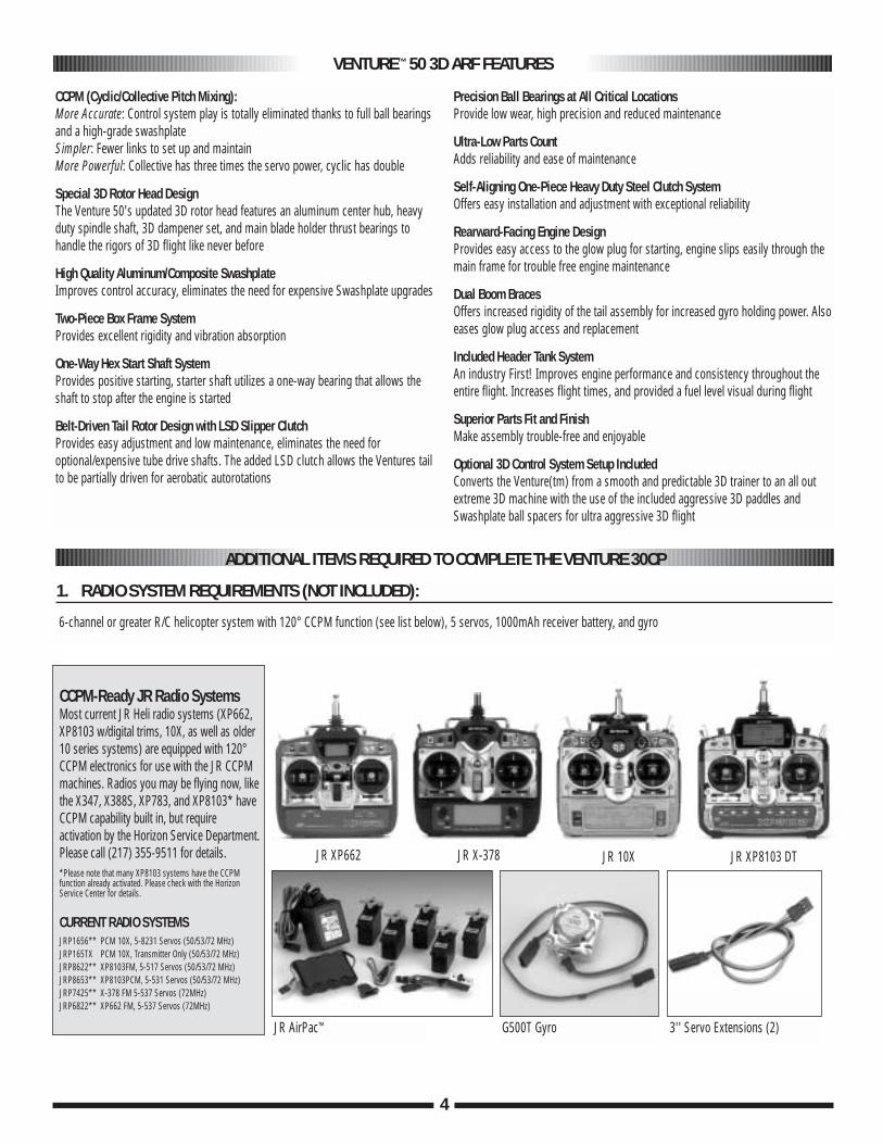
6-channel or greater R/C helicopter system with 120° CCPM function (see list below), 5 servos, 1000mAh receiver battery, and gyro
VENTURE™ 50 3D ARF FEATURES
CCPM (Cyclic/Collective Pitch Mixing):More Accurate: Control system play is totally eliminated thanks to full ball bearingsand a high-grade swashplateSimpler: Fewer links to set up and maintainMore Powerful: Collective has three times the servo power, cyclic has double
Special 3D Rotor Head DesignThe Venture 50's updated 3D rotor head features an aluminum center hub, heavyduty spindle shaft, 3D dampener set, and main blade holder thrust bearings tohandle the rigors of 3D flight like never before
High Quality Aluminum/Composite SwashplateImproves control accuracy, eliminates the need for expensive Swashplate upgrades
Two-Piece Box Frame SystemProvides excellent rigidity and vibration absorption
One-Way Hex Start Shaft SystemProvides positive starting, starter shaft utilizes a one-way bearing that allows theshaft to stop after the engine is started
Belt-Driven Tail Rotor Design with LSD Slipper ClutchProvides easy adjustment and low maintenance, eliminates the need foroptional/expensive tube drive shafts. The added LSD clutch allows the Ventures tailto be partially driven for aerobatic autorotations
Precision Ball Bearings at All Critical LocationsProvide low wear, high precision and reduced maintenance
Ultra-Low Parts CountAdds reliability and ease of maintenance
Self-Aligning One-Piece Heavy Duty Steel Clutch SystemOffers easy installation and adjustment with exceptional reliability
Rearward-Facing Engine DesignProvides easy access to the glow plug for starting, engine slips easily through themain frame for trouble free engine maintenance
Dual Boom BracesOffers increased rigidity of the tail assembly for increased gyro holding power. Alsoeases glow plug access and replacement
Included Header Tank SystemAn industry First! Improves engine performance and consistency throughout theentire flight. Increases flight times, and provided a fuel level visual during flight
Superior Parts Fit and FinishMake assembly trouble-free and enjoyable
Optional 3D Control System Setup IncludedConverts the Venture(tm) from a smooth and predictable 3D trainer to an all outextreme 3D machine with the use of the included aggressive 3D paddles andSwashplate ball spacers for ultra aggressive 3D flight
4
CCPM-Ready JR Radio SystemsMost current JR Heli radio systems (XP662,XP8103 w/digital trims, 10X, as well as older10 series systems) are equipped with 120°CCPM electronics for use with the JR CCPMmachines. Radios you may be flying now, likethe X347, X388S, XP783, and XP8103* haveCCPM capability built in, but requireactivation by the Horizon Service Department. Please call (217) 355-9511 for details.*Please note that many XP8103 systems have the CCPMfunction already activated. Please check with the HorizonService Center for details.
CURRENT RADIO SYSTEMSJRP1656** PCM 10X, 5-8231 Servos (50/53/72 MHz)JRP165TX PCM 10X, Transmitter Only (50/53/72 MHz)JRP8622** XP8103FM, 5-517 Servos (50/53/72 MHz)JRP8653** XP8103PCM, 5-531 Servos (50/53/72 MHz)JRP7425** X-378 FM 5-537 Servos (72MHz)JRP6822** XP662 FM, 5-537 Servos (72MHz)
3'' Servo Extensions (2)G500T Gyro JR AirPac™
JR XP662 JR X-378 JR 10X JR XP8103 DT
5
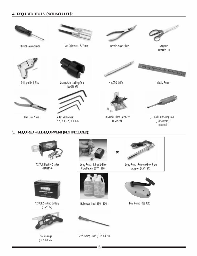
Double-Sided Servo Mounting Tape
Threadlock (blue required)
Nylon Wire Ties (secure radiowires)
2' Silicone Fuel Tubing
Fuel Filter Glow Plugs
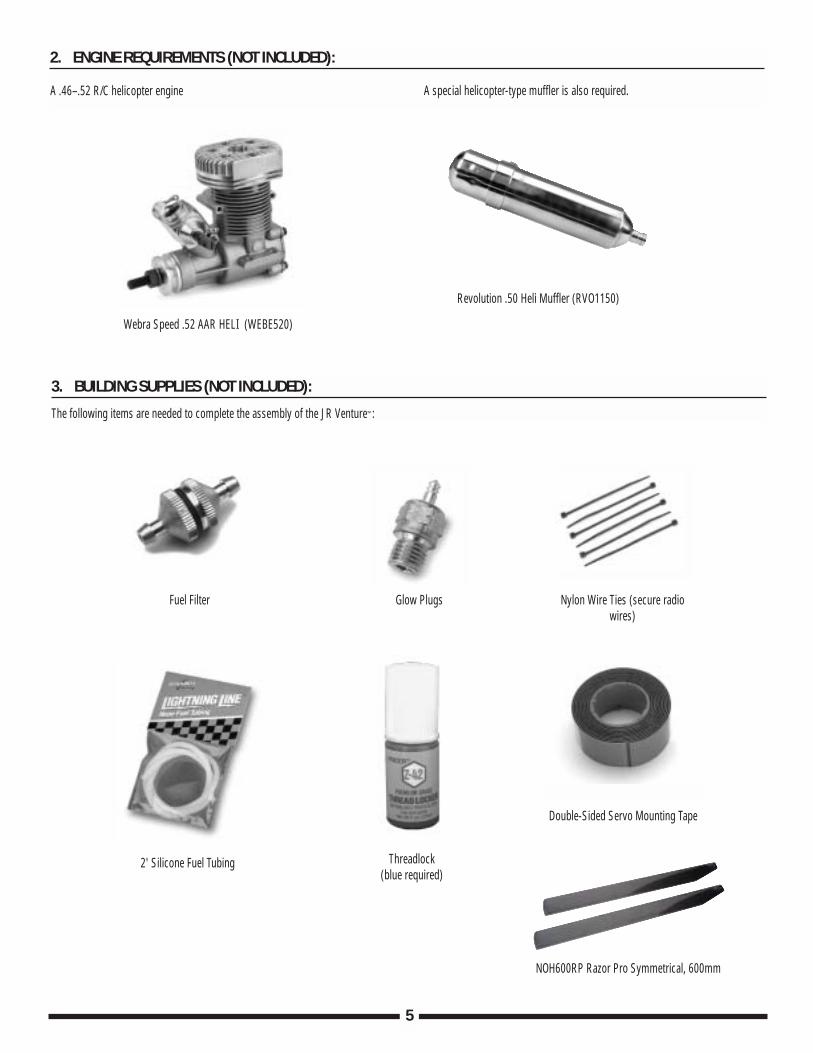
2. ENGINE REQUIREMENTS (NOT INCLUDED):
3. BUILDING SUPPLIES (NOT INCLUDED):
The following items are needed to complete the assembly of the JR Venture™:
A .46–.52 R/C helicopter engine A special helicopter-type muffler is also required.
Webra Speed .52 AAR HELI (WEBE520)
Revolution .50 Heli Muffler (RVO1150)
NOH600RP Razor Pro Symmetrical, 600mm
6
Needle-Nose Pliers
Drill and Drill Bits
Allen Wrenches: 1.5, 2.0, 2.5, 3.0 mm
Ball Link Pliers JR Ball Link Sizing Tool(JRP960219)
(optional)
Universal Blade Balancer(KSJ528)
Crankshaft Locking Tool (RVO1007)
X-ACTO Knife Metric Ruler
Scissors (DYN2511)
12-Volt Electric Starter(HAN110)
12-Volt Starting Battery(HAN102)
Long Reach 1.5-Volt GlowPlug Battery (DYN1960)
Long Reach Remote Glow PlugAdaptor (HAN121)
Helicopter Fuel, 15%–30%
Pitch Gauge(JRP960326)
Fuel Pump (KSJ860)
Hex Starting Shaft (JRP960090)
Phillips Screwdriver Nut Drivers: 4, 5, 7 mm
4. REQUIRED TOOLS (NOT INCLUDED):
5. REQUIRED FIELD EQUIPMENT (NOT INCLUDED):
or
7
Socket Head Bolt Tapping Screw Flat Washer
.05mm
.05mm
Flat Head Screw Lock Nut
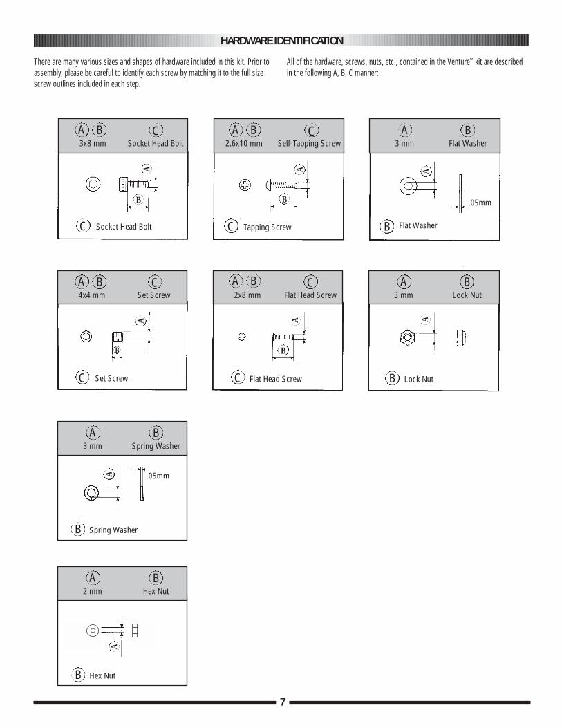
There are many various sizes and shapes of hardware included in this kit. Prior toassembly, please be careful to identify each screw by matching it to the full sizescrew outlines included in each step.
All of the hardware, screws, nuts, etc., contained in the Venture™ kit are describedin the following A, B, C manner:
C C
CA
B
A A
B
B
C3x8 mm Socket Head Bolt
Set ScrewC
A
B
C
CA A
A
2x8 mm Flat Head Screw
2.6x10 mm Self-Tapping ScrewA B
B
3 mm Flat Washer
A B
B
3 mm Lock Nut
Spring Washer
A B
B
3 mm Spring Washer
A
Hex Nut
A B
B
2 mm Hex Nut
C4x4 mm Set Screw
HARDWARE IDENTIFICATION
A B A B
A B A B
8
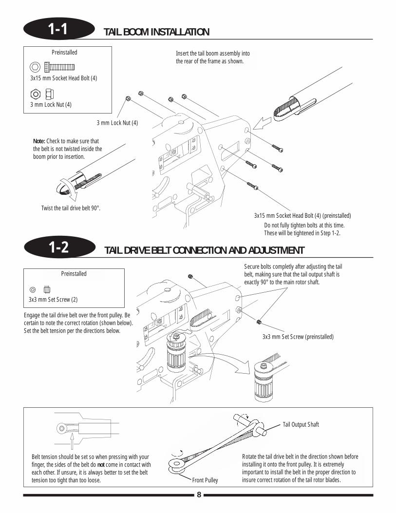
1-1 TAIL BOOM INSTALLATION
1-2 TAIL DRIVE BELT CONNECTION AND ADJUSTMENT
Engage the tail drive belt over the front pulley. Becertain to note the correct rotation (shown below).Set the belt tension per the directions below.
Secure bolts completly after adjusting the tailbelt, making sure that the tail output shaft isexactly 90° to the main rotor shaft.
Rotate the tail drive belt in the direction shown beforeinstalling it onto the front pulley. It is extremelyimportant to install the belt in the proper direction toinsure correct rotation of the tail rotor blades.
Belt tension should be set so when pressing with yourfinger, the sides of the belt do not come in contact witheach other. If unsure, it is always better to set the belttension too tight than too loose.
Insert the tail boom assembly into the rear of the frame as shown.
Note: Check to make sure thatthe belt is not twisted inside theboom prior to insertion.
Do not fully tighten bolts at this time.These will be tightened in Step 1-2.
Preinstalled
3x3 mm Set Screw (2)
3x3 mm Set Screw (preinstalled)
Tail Output Shaft
Front Pulley
3x15 mm Socket Head Bolt (4)
3x15 mm Socket Head Bolt (4) (preinstalled)
Preinstalled
3 mm Lock Nut (4)
3 mm Lock Nut (4)
Twist the tail drive belt 90°.
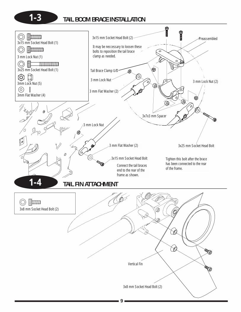
1-3 TAIL BOOM BRACE INSTALLATION
9
Connect the tail bracesend to the rear of theframe as shown.
Tighten this bolt after the bracehas been connected to the rearof the frame.
It may be neccessary to loosen thesebolts to reposition the tail braceclamp as needed.
3x15 mm Socket Head Bolt (1)3x15 mm Socket Head Bolt (2)
Tail Brace Clamp U/D
Preassembled
3x15 mm Socket Head Bolt
3x25 mm Socket Head Bolt
3 mm Lock Nut (1)
3 mm Lock Nut
3 mm Lock Nut
3 mm Flat Washer (2)
3 mm Lock Nut (2)
3x8 mm Socket Head Bolt (2)
3x8 mm Socket Head Bolt (2)
Vertical Fin
3 mm Flat Washer (2)
1-4 TAIL FIN ATTACHMENT
3x25 mm Socket Head Bolt (1)
3mm Lock Nut (5)
3mm Flat Washer (4)
3x7x3 mm Spacer
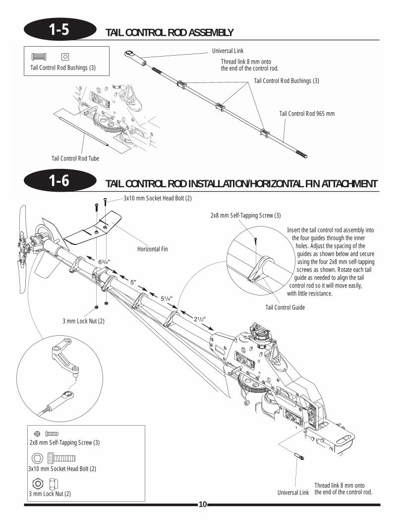
1-5 TAIL CONTROL ROD ASSEMBLY
10
1-6 TAIL CONTROL ROD INSTALLATION/HORIZONTAL FIN ATTACHMENT
Insert the tail control rod assembly intothe four guides through the inner
holes. Adjust the spacing of theguides as shown below and secureusing the four 2x8 mm self-tappingscrews as shown. Rotate each tail
guide as needed to align the tailcontrol rod so it will move easily,
with little resistance.
Thread link 8 mm ontothe end of the control rod.
63/4''
5''
51/4''
Tail Control Rod Bushings (3)
Tail Control Rod Bushings (3)
Tail Control Rod 965 mm
Tail Control Rod Tube
Universal Link
3x10 mm Socket Head Bolt (2)
Horizontal Fin
3 mm Lock Nut (2)
3 mm Lock Nut (2)
3x10 mm Socket Head Bolt (2)
2x8 mm Self-Tapping Screw (3)
2x8 mm Self-Tapping Screw (3)
Tail Control Guide
Universal LinkThread link 8 mm ontothe end of the control rod.
21/2''
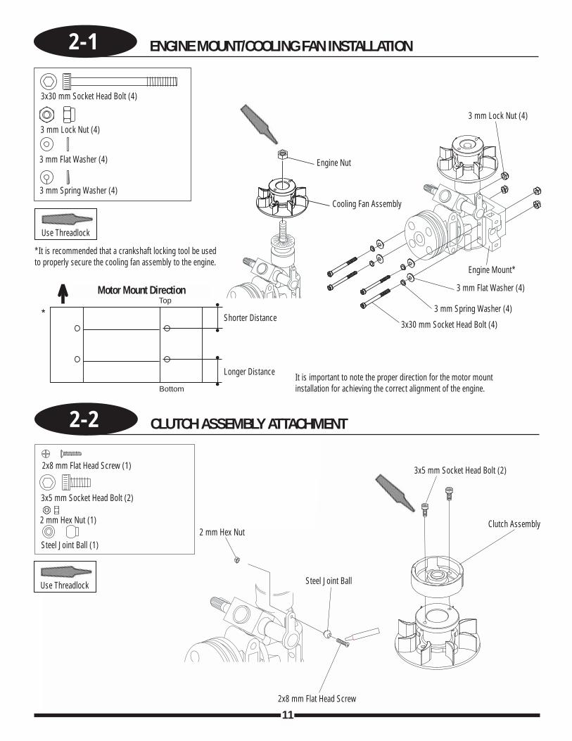
2-1 ENGINE MOUNT/COOLING FAN INSTALLATION
11
2-2 CLUTCH ASSEMBLY ATTACHMENT
Longer Distance
Shorter Distance
*It is recommended that a crankshaft locking tool be usedto properly secure the cooling fan assembly to the engine.
It is important to note the proper direction for the motor mountinstallation for achieving the correct alignment of the engine.
Top
Bottom
Motor Mount Direction
*
Use Threadlock
Use Threadlock
3x30 mm Socket Head Bolt (4)
3x30 mm Socket Head Bolt (4)
3 mm Lock Nut (4)3 mm Lock Nut (4)
3 mm Flat Washer (4)
3 mm Flat Washer (4)
3 mm Spring Washer (4)
3 mm Spring Washer (4)
Engine Nut
Engine Mount*
Cooling Fan Assembly
2x8 mm Flat Head Screw (1)
2x8 mm Flat Head Screw
3x5 mm Socket Head Bolt (2)
3x5 mm Socket Head Bolt (2)
2 mm Hex Nut (1)2 mm Hex Nut
Steel Joint Ball (1)
Steel Joint Ball
Clutch Assembly
2-2 CLUTCH ASSEMBLY ATTACHMENT
12
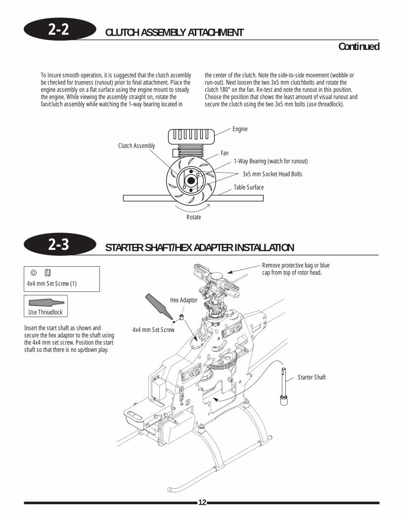
2-3 STARTER SHAFT/HEX ADAPTER INSTALLATION
To insure smooth operation, it is suggested that the clutch assemblybe checked for trueness (runout) prior to final attachment. Place theengine assembly on a flat surface using the engine mount to steadythe engine. While viewing the assembly straight on, rotate thefan/clutch assembly while watching the 1-way bearing located in
the center of the clutch. Note the side-to-side movement (wobble orrun-out). Next loosen the two 3x5 mm clutchbolts and rotate theclutch 180° on the fan. Re-test and note the runout in this position.Choose the position that shows the least amount of visual runout andsecure the clutch using the two 3x5 mm bolts (use threadlock).
Use Threadlock
4x4 mm Set Screw (1)
Engine
Fan1-Way Bearing (watch for runout)
3x5 mm Socket Head Bolts
Table Surface
Rotate
Clutch Assembly
Continued
Hex Adaptor
Remove protective bag or bluecap from top of rotor head.
4x4 mm Set Screw
Starter Shaft
Insert the start shaft as shown andsecure the hex adaptor to the shaft usingthe 4x4 mm set screw. Position the startshaft so that there is no up/down play.
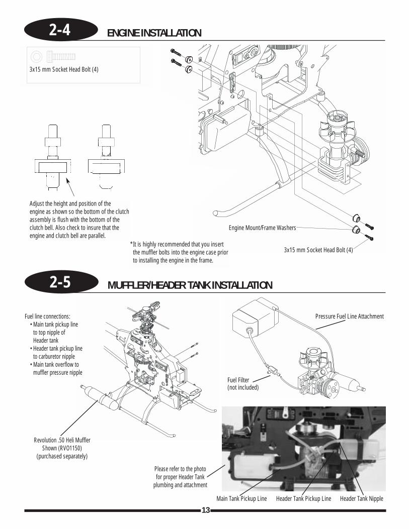
2-4 ENGINE INSTALLATION
13
2-5 MUFFLER/HEADER TANK INSTALLATION
Adjust the height and position of the engine as shown so the bottom of the clutchassembly is flush with the bottom of theclutch bell. Also check to insure that theengine and clutch bell are parallel.
*It is highly recommended that you insertthe muffler bolts into the engine case priorto installing the engine in the frame.
3x15 mm Socket Head Bolt (4)
3x15 mm Socket Head Bolt (4)
Engine Mount/Frame Washers
Pressure Fuel Line Attachment
Fuel Filter(not included)
Revolution .50 Heli MufflerShown (RVO1150)
(purchased separately)
Please refer to the photofor proper Header Tank
plumbing and attachment
Fuel line connections:• Main tank pickup line
to top nipple ofHeader tank
• Header tank pickup lineto carburetor nipple
• Main tank overflow tomuffler pressure nipple
Main Tank Pickup Line Header Tank Pickup Line Header Tank Nipple
14
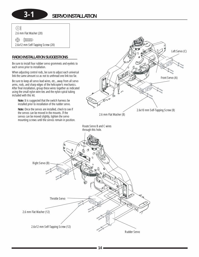
3-1 SERVO INSTALLATION
RADIO INSTALLATION SUGGESTIONS
Be sure to install four rubber servo grommets and eyelets toeach servo prior to installation.
When adjusting control rods, be sure to adjust each universallink the same amount so as not to unthread one link too far.
Be sure to keep all servo lead wires, etc., away from all servoarms, rods, and sharp edges of the helicopter’s mechanics.After final installation, group these wires together as indicatedusing the small nylon wire ties and the nylon spiral tubingincluded with this kit.
Note: It is suggested that the switch harness beinstalled prior to installation of the rudder servo.
Note: Once the servos are installed, check to see ifthe servos can be moved in the mounts. If theservos can be moved slightly, tighten the servomounting screws until the servos remain in position.
2.6 mm Flat Washer (20)
2.6 mm Flat Washer (8)
Left Servo (C)
Front Servo (A)
2.6x12 mm Self-Tapping Screw (20)
2.6x10 mm Self-Tapping Screw (8)
Right Servo (B)
Throttle Servo
2.6 mm Flat Washer (12)
2.6x12 mm Self-Tapping Screw (12)
Rudder Servo
Route Servo B and C wiresthrough this hole.
3-2 GYRO/RECEIVER/SWITCH HARNESS/BATTERY INSTALLATION
15
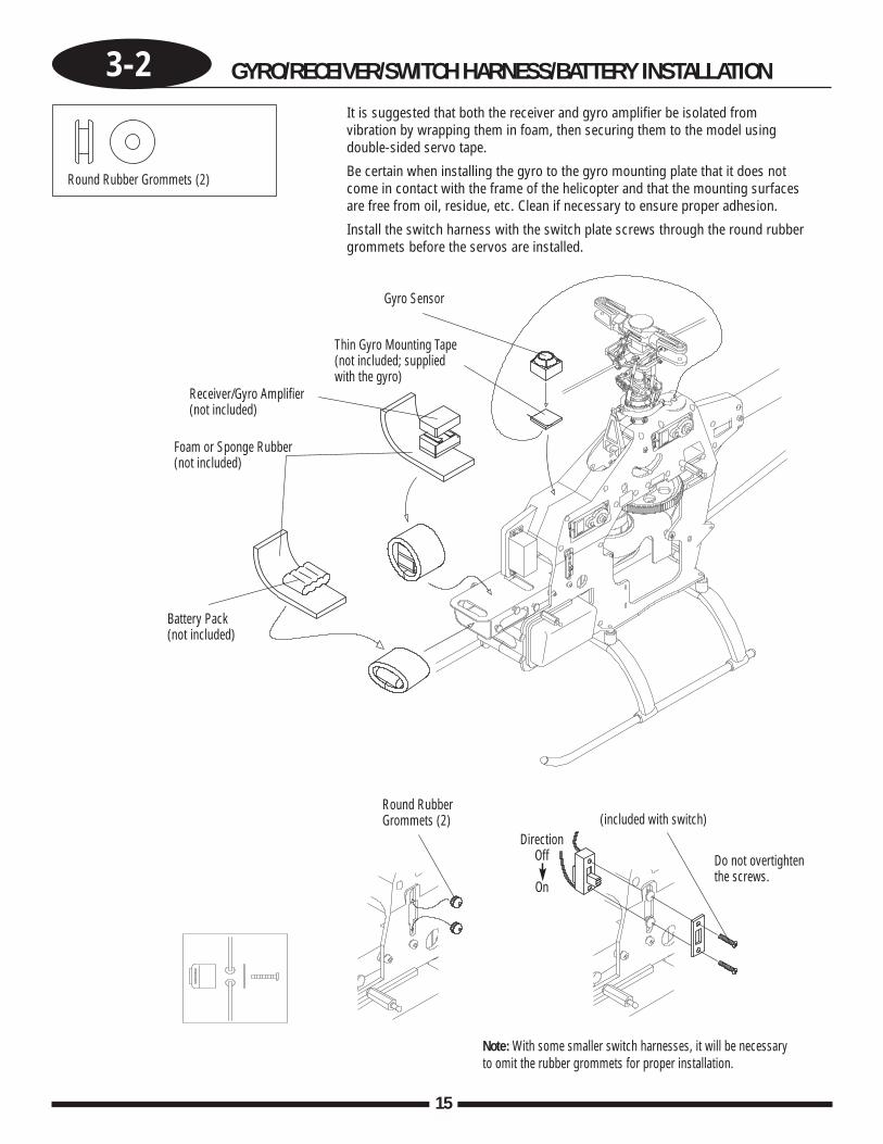
It is suggested that both the receiver and gyro amplifier be isolated fromvibration by wrapping them in foam, then securing them to the model usingdouble-sided servo tape.
Be certain when installing the gyro to the gyro mounting plate that it does notcome in contact with the frame of the helicopter and that the mounting surfacesare free from oil, residue, etc. Clean if necessary to ensure proper adhesion.
Install the switch harness with the switch plate screws through the round rubbergrommets before the servos are installed.
Round Rubber Grommets (2)
Note: With some smaller switch harnesses, it will be necessaryto omit the rubber grommets for proper installation.
Gyro Sensor
Receiver/Gyro Amplifier(not included)
Thin Gyro Mounting Tape(not included; suppliedwith the gyro)
Round RubberGrommets (2) (included with switch)
Do not overtightenthe screws.
DirectionOff
On
Foam or Sponge Rubber(not included)
Battery Pack(not included)
Continued
16
3-2 GYRO/RECEIVER/SWITCH HARNESS/BATTERY INSTALLATION
GEAR
7 CH 72MHz FM SLIMLINERECEIVER
ABC&W INTERFERENCEPROTECTION SYSTEM
BA
TT
RUDD
ELEV
A I L E
THRO
AUX1
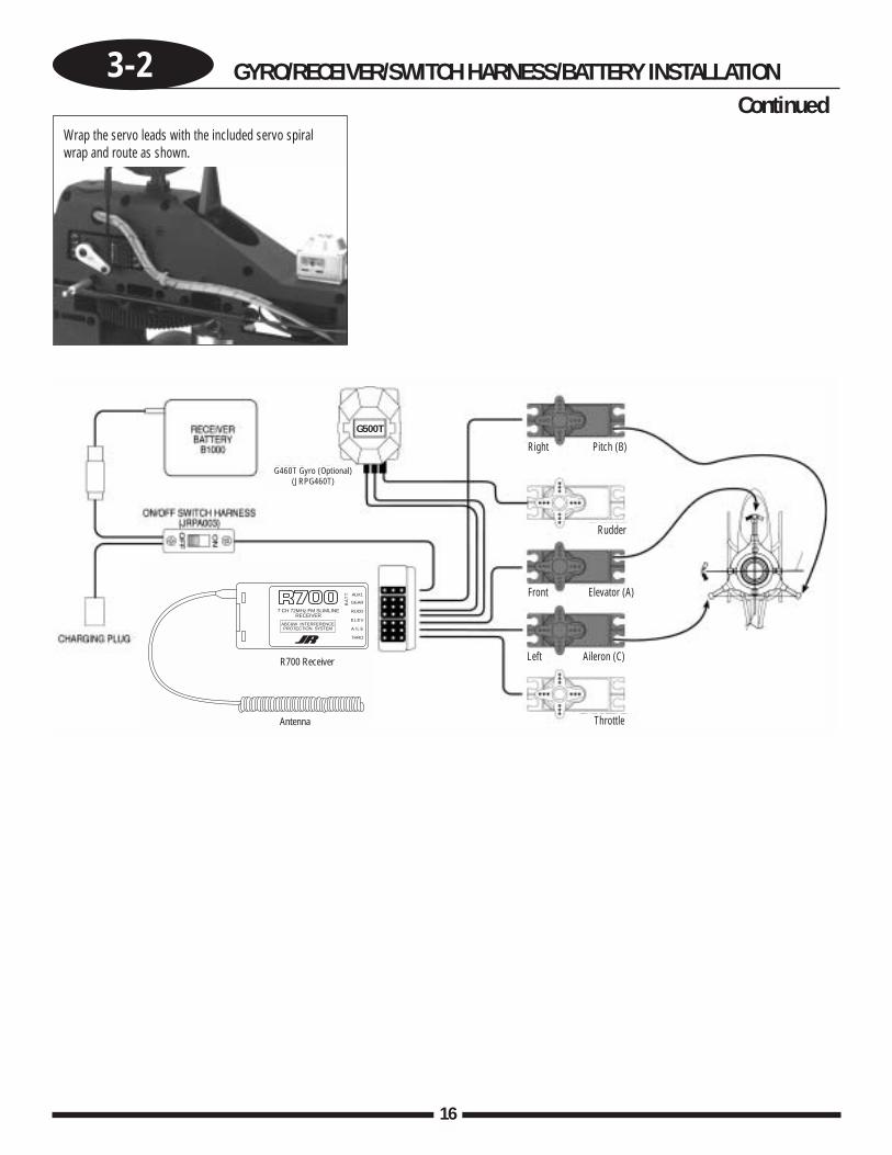
R700 Receiver
Antenna
G460T Gyro (Optional)(JRPG460T)
Wrap the servo leads with the included servo spiralwrap and route as shown.
G500T
Right Pitch (B)
Rudder
Front Elevator (A)
Left Aileron (C)
Throttle
17
UNDERSTANDING SWASHPLATE CONTROL SYSTEMS
Currently, there are several different types of control systems available on the market. Although the mechanical methods fortransferring control to the swashplate vary, the different control systems can be broken down into two categories:
One-Servo (Conventional)CCPM (Cyclic/Collective Pitch Mixing)
The following is an explanation of the two most popular types of swashplate control.
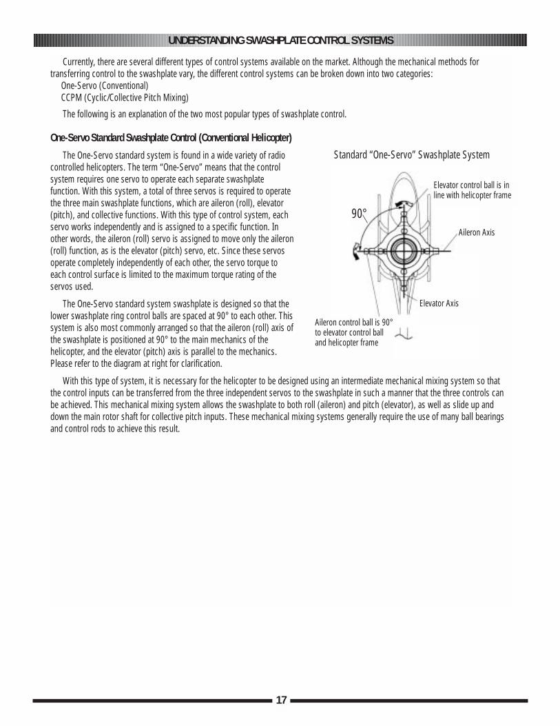
One-Servo Standard Swashplate Control (Conventional Helicopter)
The One-Servo standard system is found in a wide variety of radiocontrolled helicopters. The term “One-Servo” means that the controlsystem requires one servo to operate each separate swashplatefunction. With this system, a total of three servos is required to operatethe three main swashplate functions, which are aileron (roll), elevator(pitch), and collective functions. With this type of control system, eachservo works independently and is assigned to a specific function. Inother words, the aileron (roll) servo is assigned to move only the aileron(roll) function, as is the elevator (pitch) servo, etc. Since these servosoperate completely independently of each other, the servo torque toeach control surface is limited to the maximum torque rating of theservos used.
The One-Servo standard system swashplate is designed so that thelower swashplate ring control balls are spaced at 90° to each other. Thissystem is also most commonly arranged so that the aileron (roll) axis ofthe swashplate is positioned at 90° to the main mechanics of thehelicopter, and the elevator (pitch) axis is parallel to the mechanics.Please refer to the diagram at right for clarification.
With this type of system, it is necessary for the helicopter to be designed using an intermediate mechanical mixing system so thatthe control inputs can be transferred from the three independent servos to the swashplate in such a manner that the three controls canbe achieved. This mechanical mixing system allows the swashplate to both roll (aileron) and pitch (elevator), as well as slide up anddown the main rotor shaft for collective pitch inputs. These mechanical mixing systems generally require the use of many ball bearingsand control rods to achieve this result.
Elevator control ball is inline with helicopter frame
Aileron Axis
Elevator Axis
Aileron control ball is 90°to elevator control ball and helicopter frame
Standard “One-Servo” Swashplate System
90°
18
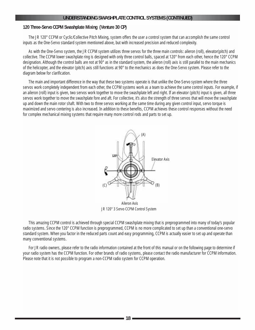
120 Three-Servo CCPM Swashplate Mixing (Venture 30 CP)
The JR 120° CCPM or Cyclic/Collective Pitch Mixing, system offers the user a control system that can accomplish the same controlinputs as the One-Servo standard system mentioned above, but with increased precision and reduced complexity.
As with the One-Servo system, the JR CCPM system utilizes three servos for the three main controls: aileron (roll), elevator(pitch) andcollective. The CCPM lower swashplate ring is designed with only three control balls, spaced at 120° from each other, hence the 120° CCPMdesignation. Although the control balls are not at 90° as in the standard system, the aileron (roll) axis is still parallel to the main mechanicsof the helicopter, and the elevator (pitch) axis still functions at 90° to the mechanics as does the One-Servo system. Please refer to thediagram below for clarification.
The main and important difference in the way that these two systems operate is that unlike the One-Servo system where the threeservos work completely independent from each other, the CCPM systems work as a team to achieve the same control inputs. For example, ifan aileron (roll) input is given, two servos work together to move the swashplate left and right. If an elevator (pitch) input is given, all threeservos work together to move the swashplate fore and aft. For collective, it’s also the strength of three servos that will move the swashplateup and down the main rotor shaft. With two to three servos working at the same time during any given control input, servo torque ismaximized and servo centering is also increased. In addition to these benefits, CCPM achieves these control responses without the need for complex mechanical mixing systems that require many more control rods and parts to set up.
This amazing CCPM control is achieved through special CCPM swashplate mixing that is preprogrammed into many of today’s popularradio systems. Since the 120° CCPM function is preprogrammed, CCPM is no more complicated to set up than a conventional one-servostandard system. When you factor in the reduced parts count and easy programming, CCPM is actually easier to set up and operate thanmany conventional systems.
For JR radio owners, please refer to the radio information contained at the front of this manual or on the following page to determine ifyour radio system has the CCPM function. For other brands of radio systems, please contact the radio manufacturer for CCPM information.Please note that it is not possible to program a non-CCPM radio system for CCPM operation.
UNDERSTANDING SWASHPLATE CONTROL SYSTEMS (CONTINUED)
Elevator Axis120°
JR 120° 3 Servo CCPM Control SystemAileron Axis
(A)
(B)(C)
19
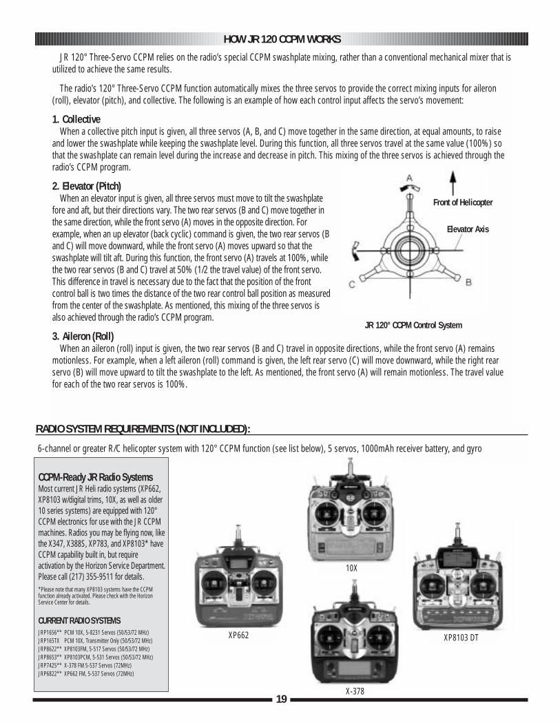
JR 120° Three-Servo CCPM relies on the radio’s special CCPM swashplate mixing, rather than a conventional mechanical mixer that isutilized to achieve the same results.
The radio’s 120° Three-Servo CCPM function automatically mixes the three servos to provide the correct mixing inputs for aileron(roll), elevator (pitch), and collective. The following is an example of how each control input affects the servo’s movement:
1. CollectiveWhen a collective pitch input is given, all three servos (A, B, and C) move together in the same direction, at equal amounts, to raise
and lower the swashplate while keeping the swashplate level. During this function, all three servos travel at the same value (100%) sothat the swashplate can remain level during the increase and decrease in pitch. This mixing of the three servos is achieved through theradio’s CCPM program.
2. Elevator (Pitch)When an elevator input is given, all three servos must move to tilt the swashplate
fore and aft, but their directions vary. The two rear servos (B and C) move together inthe same direction, while the front servo (A) moves in the opposite direction. Forexample, when an up elevator (back cyclic) command is given, the two rear servos (Band C) will move downward, while the front servo (A) moves upward so that theswashplate will tilt aft. During this function, the front servo (A) travels at 100%, whilethe two rear servos (B and C) travel at 50% (1/2 the travel value) of the front servo.This difference in travel is necessary due to the fact that the position of the frontcontrol ball is two times the distance of the two rear control ball position as measuredfrom the center of the swashplate. As mentioned, this mixing of the three servos isalso achieved through the radio’s CCPM program.
3. Aileron (Roll) When an aileron (roll) input is given, the two rear servos (B and C) travel in opposite directions, while the front servo (A) remains
motionless. For example, when a left aileron (roll) command is given, the left rear servo (C) will move downward, while the right rearservo (B) will move upward to tilt the swashplate to the left. As mentioned, the front servo (A) will remain motionless. The travel valuefor each of the two rear servos is 100%.
HOW JR 120 CCPM WORKS
Front of Helicopter
Elevator Axis
JR 120° CCPM Control System
RADIO SYSTEM REQUIREMENTS (NOT INCLUDED):
6-channel or greater R/C helicopter system with 120° CCPM function (see list below), 5 servos, 1000mAh receiver battery, and gyro
XP662
10X
XP8103 DT
X-378
CCPM-Ready JR Radio SystemsMost current JR Heli radio systems (XP662,XP8103 w/digital trims, 10X, as well as older10 series systems) are equipped with 120°CCPM electronics for use with the JR CCPMmachines. Radios you may be flying now, likethe X347, X388S, XP783, and XP8103* haveCCPM capability built in, but requireactivation by the Horizon Service Department. Please call (217) 355-9511 for details.*Please note that many XP8103 systems have the CCPMfunction already activated. Please check with the HorizonService Center for details.
CURRENT RADIO SYSTEMSJRP1656** PCM 10X, 5-8231 Servos (50/53/72 MHz)JRP165TX PCM 10X, Transmitter Only (50/53/72 MHz)JRP8622** XP8103FM, 5-517 Servos (50/53/72 MHz)JRP8653** XP8103PCM, 5-531 Servos (50/53/72 MHz)JRP7425** X-378 FM 5-537 Servos (72MHz)JRP6822** XP662 FM, 5-537 Servos (72MHz)
20
CCPM SOFTWARE ACTIVATION AND INITIAL ADJUSTMENT
The following activation and setup procedure should be used for all JR XP652 and XP662 systems. Please note that the XF622 and XP6426-channel systems do not have the required CCPM software and therefore cannot be activated by the Horizon Service Center.
Prior to activating the CCPM function, it is first suggested that the Data Reset function be performed to reset the desired model number tobe used back to the factory default settings. If you are using a new radio system, proceed to Step C.
Caution: Prior to performing the Data Reset function, it will be necessary to select the desired model number to be used.
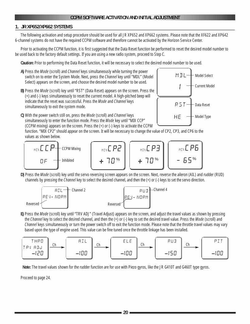
A) Press the Mode (scroll) and Channel keys simultaneously while turning the powerswitch on to enter the System Mode. Next, press the Channel key until “MDL” (ModelSelect) appears on the screen, and choose the desired model number to be used.
B) Press the Mode (scroll) key until “RST” (Data Reset) appears on the screen. Press the(+) and (-) keys simultaneously to reset the current model. A high-pitched beep willindicate that the reset was successful. Press the Mode and Channel keyssimultaneously to exit the system mode.
C) With the power switch still on, press the Mode (scroll) and Channel keyssimultaneously to enter the function mode. Press the Mode key until “MIX CCP”(CCPM mixing) appears on the screen. Press the (+) or (-) keys to activate the CCPMfunction. “MIX CP2” should appear on the screen. It will be necessary to change the value of CP2, CP3, and CP6 to the values as shown below.
D) Press the Mode (scroll) key until the servo reversing screen appears on the screen. Next, reverse the aileron (AIL) and rudder (RUD)channels by pressing the Channel key to select the desired channel, and then the (+) or (-) keys to set the servo direction.
E) Press the Mode (scroll) key until “TRV ADJ” (Travel Adjust) appears on the screen, and adjust the travel values as shown by pressingthe Channel key to select the desired channel, and then the (+) or (-) key to set the desired travel value. Press the Mode (scroll) andChannel keys simultaneously or turn the power switch off to exit the function mode. Please note that the throttle travel values may varybased upon the type of engine used. This value can be fine tuned once the throttle linkage has been installed.
Note: The travel values shown for the rudder function are for use with Piezo gyros, like the JR G410T and G460T type gyros.
Proceed to page 24.
1. JR XP652/XP662 SYSTEMS
mdl
1
Model Select
Current Model
rst
he
Data Reset
Model Type
mixCCP
of
CCPM Mixing
Inhibited
ail
rev.norm
rud
rev.norm
mixCP2
+ 70%
mixCP3
+ 70%
mixCP6
— 65%
Channel 2
Reversed
Channel 4
Reversed
thro
trv adj
-120
ail
-100
ele
-100
rud
-150
pit
-100
Ch Ch Ch Ch
21
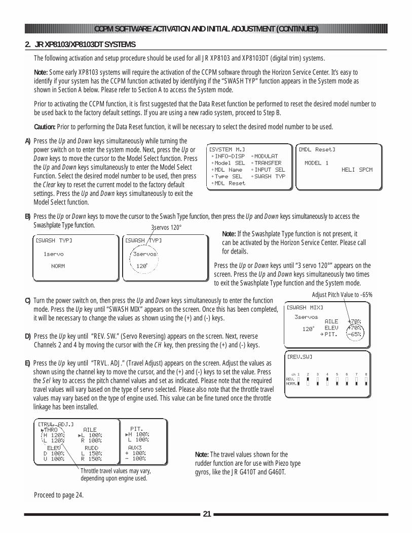
The following activation and setup procedure should be used for all JR XP8103 and XP8103DT (digital trim) systems.
Note: Some early XP8103 systems will require the activation of the CCPM software through the Horizon Service Center. It’s easy to identify if your system has the CCPM function activated by identifying if the “SWASH TYP” function appears in the System mode as shown in Section A below. Please refer to Section A to access the System mode.
Prior to activating the CCPM function, it is first suggested that the Data Reset function be performed to reset the desired model number tobe used back to the factory default settings. If you are using a new radio system, proceed to Step B.
Caution: Prior to performing the Data Reset function, it will be necessary to select the desired model number to be used.
A) Press the Up and Down keys simultaneously while turning thepower switch on to enter the system mode. Next, press the Up orDown keys to move the cursor to the Model Select function. Pressthe Up and Down keys simultaneously to enter the Model SelectFunction. Select the desired model number to be used, then pressthe Clear key to reset the current model to the factory defaultsettings. Press the Up and Down keys simultaneously to exit theModel Select function.
B) Press the Up or Down keys to move the cursor to the Swash Type function, then press the Up and Down keys simultaneously to access theSwashplate Type function.
Note: If the Swashplate Type function is not present, it can be activated by the Horizon Service Center. Please call for details.
Press the Up or Down keys until “3 servo 120°” appears on thescreen. Press the Up and Down keys simultaneously two timesto exit the Swashplate Type function and the System mode.
C) Turn the power switch on, then press the Up and Down keys simultaneously to enter the functionmode. Press the Up key until “SWASH MIX” appears on the screen. Once this has been completed,it will be necessary to change the values as shown using the (+) and (-) keys.
D) Press the Up key until “REV. SW.” (Servo Reversing) appears on the screen. Next, reverseChannels 2 and 4 by moving the cursor with the CH key, then pressing the (+) and (-) keys.
E) Press the Up key until “TRVL. ADJ.” (Travel Adjust) appears on the screen. Adjust the values asshown using the channel key to move the cursor, and the (+) and (-) keys to set the value. Press the Sel key to access the pitch channel values and set as indicated. Please note that the requiredtravel values will vary based on the type of servo selected. Please also note that the throttle travelvalues may vary based on the type of engine used. This value can be fine tuned once the throttlelinkage has been installed.
Proceed to page 24.
CCPM SOFTWARE ACTIVATION AND INITIAL ADJUSTMENT (CONTINUED)
2. JR XP8103/XP8103DT SYSTEMS
[SYSTEM M.]
• INFO-DISP
• Model SEL
• MDL Name
• Type SEL
• MDL Reset
• MODULAT
• TRANSFER
• INPUT SEL
• SWASH TYP
[MDL Reset]
MODEL 1
HELI SPCM
PIT.
£H 100%
L 100%
AUX3
+ 100%
- 100%
[TRVL ADJ.]
£THRO
H 120%
L 120%
AILE
£L 100%
R 100%
ELEV
D 100%
U 100%
RUDD
£L 150%
R 150%
[SWASH TYP]
1servo
NORM
[SWASH MIX]
3servos
120•
[SWASH TYP]
3servos
120•
3servos 120°
AILE +70%
ELEV +70%
∞ PIT. -65%
Adjust Pitch Value to -65%
Throttle travel values may vary,depending upon engine used.
[REV.SW]
1 2 3 4 5 6 7 8ch
REV.
NORM.
Note: The travel values shown for the rudder function are for use with Piezo type gyros, like the JR G410T and G460T.
CCPM SOFTWARE ACTIVATION AND INITIAL ADJUSTMENT (CONTINUED)
22
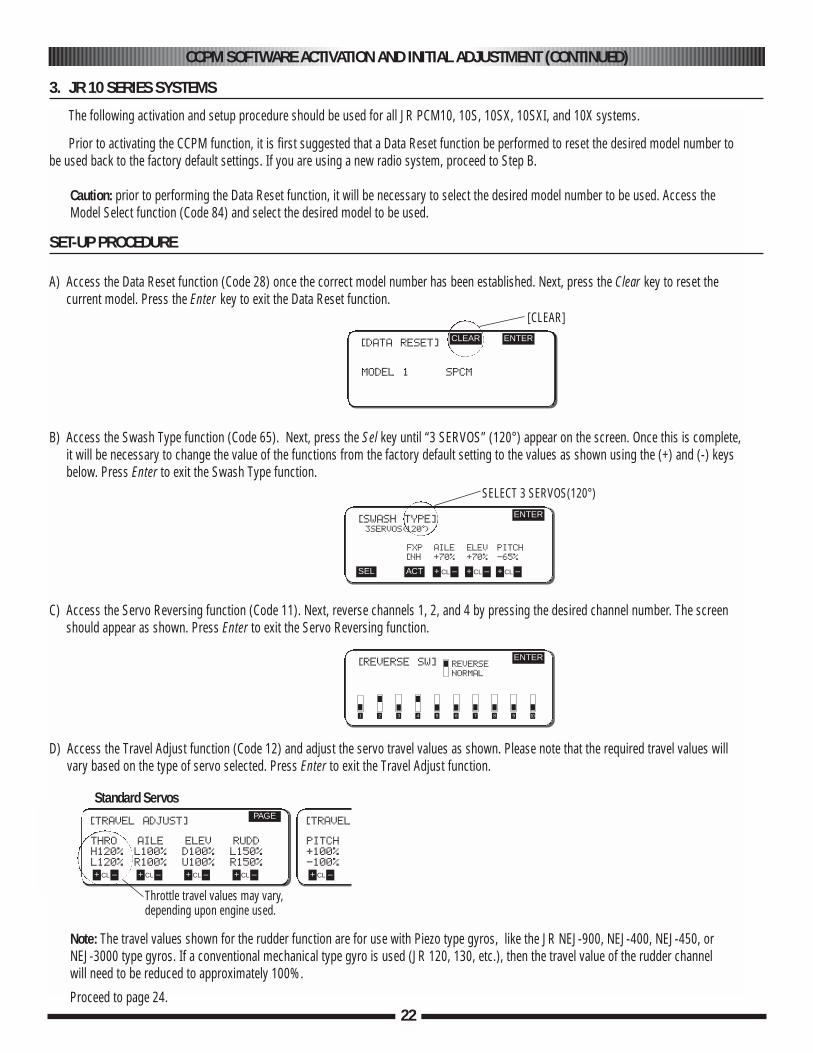
The following activation and setup procedure should be used for all JR PCM10, 10S, 10SX, 10SXI, and 10X systems.
Prior to activating the CCPM function, it is first suggested that a Data Reset function be performed to reset the desired model number tobe used back to the factory default settings. If you are using a new radio system, proceed to Step B.
Caution: prior to performing the Data Reset function, it will be necessary to select the desired model number to be used. Access theModel Select function (Code 84) and select the desired model to be used.
A) Access the Data Reset function (Code 28) once the correct model number has been established. Next, press the Clear key to reset thecurrent model. Press the Enter key to exit the Data Reset function.
B) Access the Swash Type function (Code 65). Next, press the Sel key until “3 SERVOS” (120°) appear on the screen. Once this is complete,it will be necessary to change the value of the functions from the factory default setting to the values as shown using the (+) and (-) keysbelow. Press Enter to exit the Swash Type function.
C) Access the Servo Reversing function (Code 11). Next, reverse channels 1, 2, and 4 by pressing the desired channel number. The screenshould appear as shown. Press Enter to exit the Servo Reversing function.
D) Access the Travel Adjust function (Code 12) and adjust the servo travel values as shown. Please note that the required travel values willvary based on the type of servo selected. Press Enter to exit the Travel Adjust function.
Note: The travel values shown for the rudder function are for use with Piezo type gyros, like the JR NEJ-900, NEJ-400, NEJ-450, or NEJ-3000 type gyros. If a conventional mechanical type gyro is used (JR 120, 130, etc.), then the travel value of the rudder channel will need to be reduced to approximately 100%.
3. JR 10 SERIES SYSTEMS
SET-UP PROCEDURE
[DATA RESET]
MODEL 1 SPCM
CLEAR ENTER
[SWASH TYPE]3SERVOS(120•)
FXP AILE ELEV PITCH
[NH +70% +70% -65%
ENTER
SEL ACT + –CL + –CL + –CL
[REVERSE SW] REVERSE
NORMAL
ENTER
1 2 3 4 5 6 7 8 9 10
[TRAVEL ADJUST]
THRO AILE ELEV RUDD
H120% L100% D100% L150%
L120% R100% U100% R150%
PAGE
+ –CL + –CL + –CL + –CL
[TRAVEL ADJUST]
PITCH
+100%
-100%
+ –CL + –CL + –CL
[CLEAR]
SELECT 3 SERVOS(120°)
Standard Servos
Throttle travel values may vary,depending upon engine used.
Proceed to page 24.
CCPM SOFTWARE ACTIVATION AND INITIAL ADJUSTMENT (CONTINUED)
4. JR X-378 SYSTEMS
23
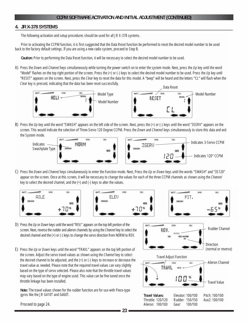
The following activation and setup procedures should be used for all JR X-378 systems.
Prior to activating the CCPM function, it is first suggested that the Data Reset function be performed to reset the desired model number to be usedback to the factory default settings. If you are using a new radio system, proceed to Step B.
Caution: Prior to performing the Data Reset function, it will be necessary to select the desired model number to be used.
A) Press the Down and Channel keys simultaneously while turning the power switch on to enter the system mode. Next, press the Up key until the word“Model” flashes on the top right portion of the screen. Press the (+) or (-) keys to select the desired model number to be used. Press the Up key until“RESET” appears on the screen. Next, press the Clear key to reset the data for this model. A “beep” will be heard and the letters “CL” will flash when theClear key is pressed, indicating that the data has been reset successfully.
B) Press the Up key until the word “SWASH” appears on the left side of the screen. Next, press the (+) or (-) keys until the word “3SERV” appears on thescreen. This would indicate the selection of Three-Servo 120 Degree CCPM. Press the Down and Channel keys simultaneously to store this data and exitthe System mode.
C) Press the Down and Channel keys simultaneously to enter the Function mode. Next, Press the Up or Down keys until the words “SWASH” and “3S120”appear on the screen. Once at this screen, it will be necessary to change the values for each of the three CCPM channels as shown using the Channelkey to select the desired channel, and the (+) and (-) keys to alter the values.
D) Press the Up or Down keys until the word “REV.” appears on the top left portion of thescreen. Next, reverse the rudder and aileron channels by using the Channel key to select thedesired channel and the (+) or (-) keys to change the servo direction from NORM to REV.
E) Press the Up or Down keys until the word “TRAVL” appears on the top left portion ofthe screen. Adjust the servo travel values as shown using the Channel key to selectthe desired channel to be adjusted, and the (+) or (-) keys to increase or decrease thetravel value as needed. Please note that the required travel values can vary slightlybased on the type of servo selected. Please also note that the throttle travel valuesmay vary based on the type of engine used. This value can be fine tuned once thethrottle linkage has been installed.
Note: The travel values shown for the rudder function are for use with Piezo-type gyros like the JR G410T and G460T.
Proceed to page 24.
Model Type
Model Number
Model Number
Data Reset
IndicatesSwashplate Type
Indicates 3-Servo CCPM
Indicates 120° CCPM
3SERV
120
AILE
+70∞
ELEV
+70∞
PIT.
-65∞
RUDD
Rudder Channel
Direction (normal or reverse)
Aileron ChannelTravel Adjust Function
Travel Value
Travel Values:Throttle: 120/120Aileron: 100/100
Elevator: 100/100Rudder: 150/150Gear: 100/100
Pitch: 100/100Aux2: 100/100
IMPORTANT CCPM PROGRAMMING GUIDELINES
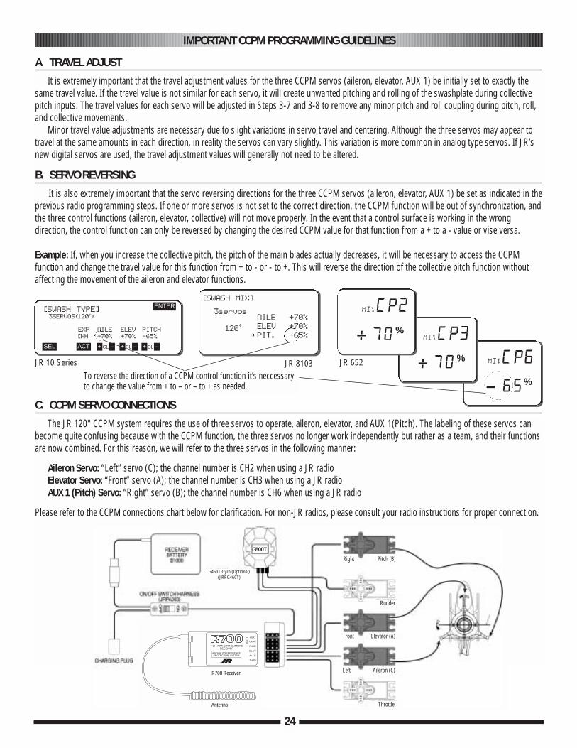
It is extremely important that the travel adjustment values for the three CCPM servos (aileron, elevator, AUX 1) be initially set to exactly thesame travel value. If the travel value is not similar for each servo, it will create unwanted pitching and rolling of the swashplate during collectivepitch inputs. The travel values for each servo will be adjusted in Steps 3-7 and 3-8 to remove any minor pitch and roll coupling during pitch, roll,and collective movements.
Minor travel value adjustments are necessary due to slight variations in servo travel and centering. Although the three servos may appear totravel at the same amounts in each direction, in reality the servos can vary slightly. This variation is more common in analog type servos. If JR’snew digital servos are used, the travel adjustment values will generally not need to be altered.
A. TRAVEL ADJUST
B. SERVO REVERSING
[SWASH TYPE]3SERVOS(120•)
EXP AILE ELEV PITCH
[NH +70% +70% -65%
ENTER
SEL ACT + –CL + –CL + –CL
To reverse the direction of a CCPM control function it’s neccessaryto change the value from + to – or – to + as needed.
[SWASH MIX]
3servos
120•
AILE +70%
ELEV +70%
∞ PIT. -65%
24
It is also extremely important that the servo reversing directions for the three CCPM servos (aileron, elevator, AUX 1) be set as indicated in theprevious radio programming steps. If one or more servos is not set to the correct direction, the CCPM function will be out of synchronization, andthe three control functions (aileron, elevator, collective) will not move properly. In the event that a control surface is working in the wrongdirection, the control function can only be reversed by changing the desired CCPM value for that function from a + to a - value or vise versa.
Example: If, when you increase the collective pitch, the pitch of the main blades actually decreases, it will be necessary to access the CCPMfunction and change the travel value for this function from + to - or - to +. This will reverse the direction of the collective pitch function withoutaffecting the movement of the aileron and elevator functions.
mixCP6
- 65%
mixCP3
+ 70%
mixCP2
+ 70%
The JR 120° CCPM system requires the use of three servos to operate, aileron, elevator, and AUX 1(Pitch). The labeling of these servos canbecome quite confusing because with the CCPM function, the three servos no longer work independently but rather as a team, and their functionsare now combined. For this reason, we will refer to the three servos in the following manner:
Aileron Servo: “Left” servo (C); the channel number is CH2 when using a JR radioElevator Servo: “Front” servo (A); the channel number is CH3 when using a JR radioAUX 1 (Pitch) Servo: “Right” servo (B); the channel number is CH6 when using a JR radio
Please refer to the CCPM connections chart below for clarification. For non-JR radios, please consult your radio instructions for proper connection.
C. CCPM SERVO CONNECTIONS
JR 10 Series JR 8103 JR 652
GEAR
7 CH 72MHz FM SLIMLINERECEIVER
ABC&W INTERFERENCEPROTECTION SYSTEM
BA
TT
RUDD
ELEV
A I L E
THRO
AUX1
R700 Receiver
Antenna
G460T Gyro (Optional)(JRPG460T)
G500T
Right Pitch (B)
Rudder
Front Elevator (A)
Left Aileron (C)
Throttle
3-3 CCPM SERVO ARM PREPARATION AND INSTALLATION
25
2x10 mm Flat Head Screw (3)
Steel Joint Ball (3)
2 mm Hex Nut (3)
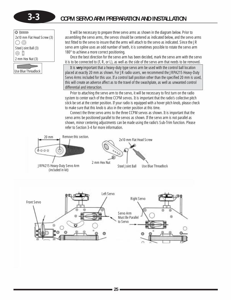
It will be necessary to prepare three servo arms as shown in the diagram below. Prior toassembling the servo arms, the servos should be centered as indicated below, and the servo armstest fitted to the servo to insure that the arms will attach to the servo as indicated. Since the JRservo arm spline uses an odd number of teeth, it is sometimes possible to rotate the servo arm180° to achieve a more correct positioning.
Once the best direction for the servo arm has been decided, mark the servo arm with the servoit is to be connected to (F, R, or L), as well as the side of the servo arm that needs to be removed.
It is very important that a heavy-duty type servo arm be used with the control ball locationplaced at exactly 20 mm as shown. For JR radio users, we recommend the JRPA215 Heavy-DutyServo Arms included for this use. If a control ball position other than the specified 20 mm is used,this will create an adverse affect as to the travel of the swashplate, as well as unwanted controldifferential and interaction.
Prior to attaching the servo arm to the servo, it will be necessary to first turn on the radiosystem to center each of the three CCPM servos. It is important that the radio’s collective pitchstick be set at the center position. If your radio is equipped with a hover pitch knob, please checkto make sure that this knob is also in the center position at this time.
Connect the three servo arms to the three CCPM servos as shown. It is important that theservo arms be positioned parallel to the servos as shown. If the servo arm is not parallel asshown, minor centering adjustments can be made using the radio’s Sub-Trim function. Pleaserefer to Section 3-4 for more information.
Use Blue Threadlock
Steel Joint Ball2 mm Hex Nut
Front Servo
Left ServoRight Servo
Servo Arm Must Be Parallel to Servo
2x10 mm Flat Head ScrewRemove this section.
JRPA215 Heavy-Duty Servo Arm (included in kit)
20 mm
Use Blue Threadlock
26
3-4 CCPM SERVO CENTERING WITH THE SUB-TRIM FUNCTION
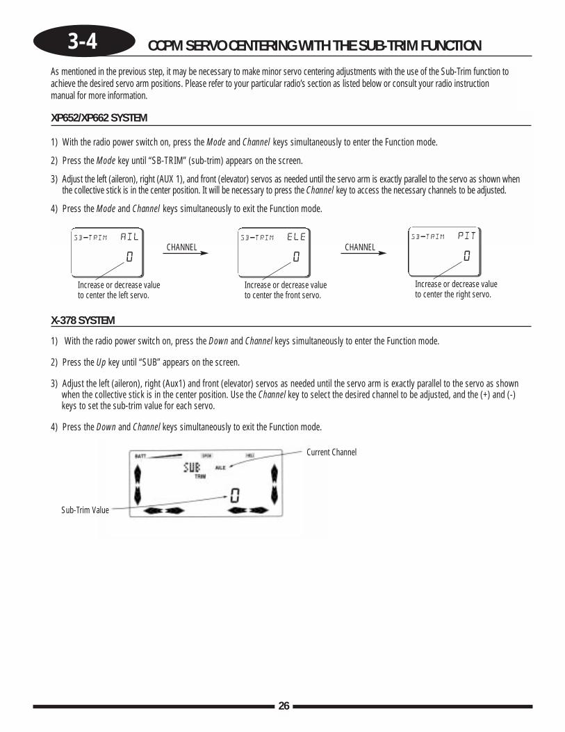
As mentioned in the previous step, it may be necessary to make minor servo centering adjustments with the use of the Sub-Trim function toachieve the desired servo arm positions. Please refer to your particular radio’s section as listed below or consult your radio instructionmanual for more information.
XP652/XP662 SYSTEM
1) With the radio power switch on, press the Mode and Channel keys simultaneously to enter the Function mode.
2) Press the Mode key until “SB-TRIM” (sub-trim) appears on the screen.
3) Adjust the left (aileron), right (AUX 1), and front (elevator) servos as needed until the servo arm is exactly parallel to the servo as shown whenthe collective stick is in the center position. It will be necessary to press the Channel key to access the necessary channels to be adjusted.
4) Press the Mode and Channel keys simultaneously to exit the Function mode.
CHANNEL CHANNELsb-trim ail
0
Increase or decrease valueto center the left servo.
sb-trim ele
0
Increase or decrease valueto center the front servo.
sb-trim pit
0
Increase or decrease valueto center the right servo.
X-378 SYSTEM
1) With the radio power switch on, press the Down and Channel keys simultaneously to enter the Function mode.
2) Press the Up key until “SUB” appears on the screen.
3) Adjust the left (aileron), right (Aux1) and front (elevator) servos as needed until the servo arm is exactly parallel to the servo as shown when the collective stick is in the center position. Use the Channel key to select the desired channel to be adjusted, and the (+) and (-) keys to set the sub-trim value for each servo.
4) Press the Down and Channel keys simultaneously to exit the Function mode.
Current Channel
Sub-Trim Value
3-4 CCPM SERVO CENTERING WITH THE SUB-TRIM FUNCTION
27
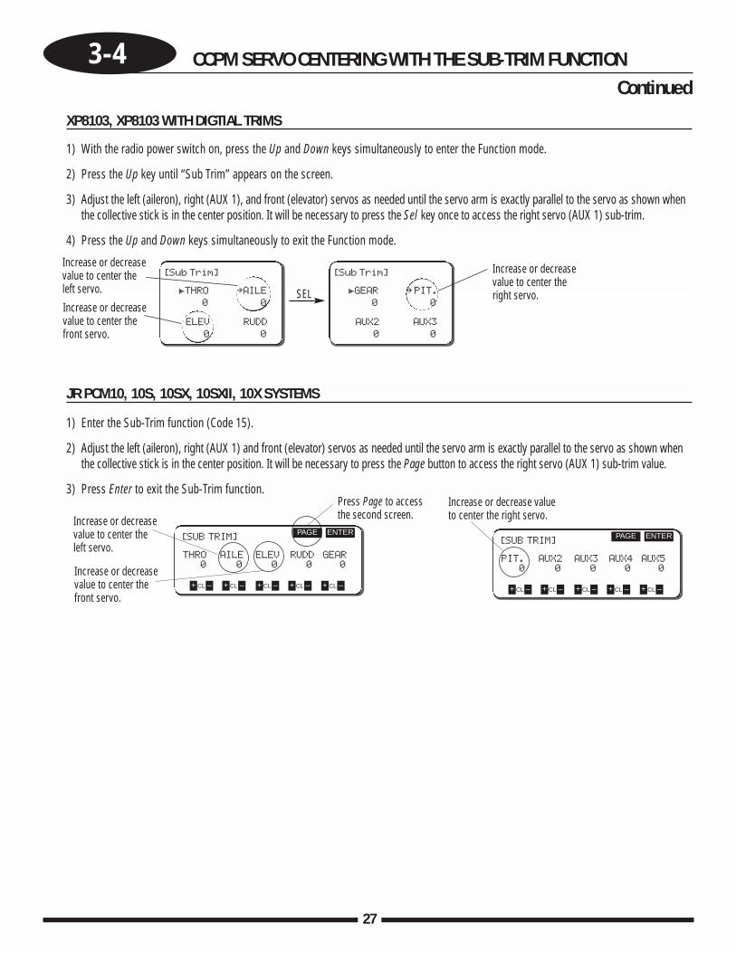
JR PCM10, 10S, 10SX, 10SXII, 10X SYSTEMS
1) Enter the Sub-Trim function (Code 15).
2) Adjust the left (aileron), right (AUX 1) and front (elevator) servos as needed until the servo arm is exactly parallel to the servo as shown whenthe collective stick is in the center position. It will be necessary to press the Page button to access the right servo (AUX 1) sub-trim value.
3) Press Enter to exit the Sub-Trim function.
XP8103, XP8103 WITH DIGTIAL TRIMS
1) With the radio power switch on, press the Up and Down keys simultaneously to enter the Function mode.
2) Press the Up key until “Sub Trim” appears on the screen.
3) Adjust the left (aileron), right (AUX 1), and front (elevator) servos as needed until the servo arm is exactly parallel to the servo as shown whenthe collective stick is in the center position. It will be necessary to press the Sel key once to access the right servo (AUX 1) sub-trim.
4) Press the Up and Down keys simultaneously to exit the Function mode.
[SUB TRIM]
THRO AILE ELEV RUDD GEAR
0 0 0 0 0
ENTERPAGE
+ –CL + –CL + –CL + –CL + –CL
Press Page to accessthe second screen.Increase or decrease
value to center theleft servo.
Increase or decreasevalue to center thefront servo.
[SUB TRIM]
PIT. AUX2 AUX3 AUX4 AUX5
0 0 0 0 0
ENTERPAGE
+ –CL + –CL + –CL + –CL + –CL
Increase or decrease value to center the right servo.
[Sub Trim]
£THRO ∞AILE
0 0
ELEV RUDD
0 0
[Sub Trim]
£GEAR ∞PIT.
0 0
AUX2 AUX3
0 0
Increase or decreasevalue to center thefront servo.
Increase or decreasevalue to center theright servo.
Increase or decreasevalue to center theleft servo. SEL
Continued
28
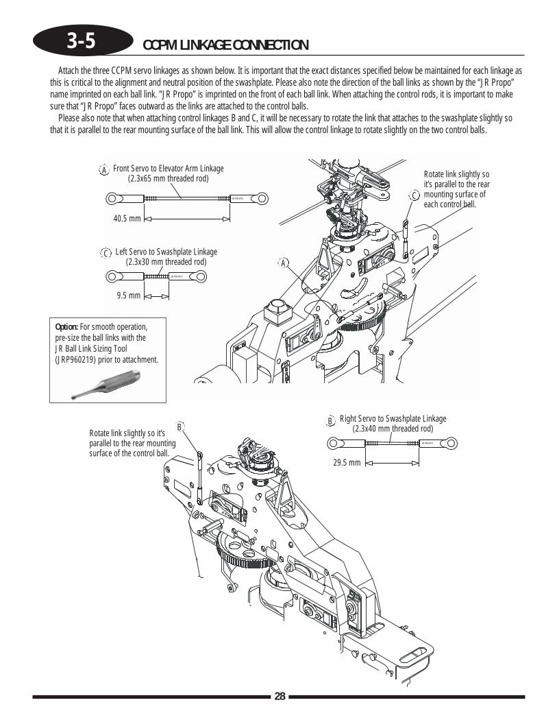
3-5 CCPM LINKAGE CONNECTION
Attach the three CCPM servo linkages as shown below. It is important that the exact distances specified below be maintained for each linkage asthis is critical to the alignment and neutral position of the swashplate. Please also note the direction of the ball links as shown by the “JR Propo”name imprinted on each ball link. “JR Propo” is imprinted on the front of each ball link. When attaching the control rods, it is important to makesure that “JR Propo” faces outward as the links are attached to the control balls.
Please also note that when attaching control linkages B and C, it will be necessary to rotate the link that attaches to the swashplate slightly sothat it is parallel to the rear mounting surface of the ball link. This will allow the control linkage to rotate slightly on the two control balls.
Option: For smooth operation, pre-size the ball links with the JR Ball Link Sizing Tool(JRP960219) prior to attachment.
Rotate link slightly soit’s parallel to the rearmounting surface ofeach control ball.
Rotate link slightly so it’sparallel to the rear mountingsurface of the control ball.
Front Servo to Elevator Arm Linkage(2.3x65 mm threaded rod)
Left Servo to Swashplate Linkage(2.3x30 mm threaded rod)
Right Servo to Swashplate Linkage(2.3x40 mm threaded rod)
40.5 mm
9.5 mm
29.5 mm
A
A
C
C
BB
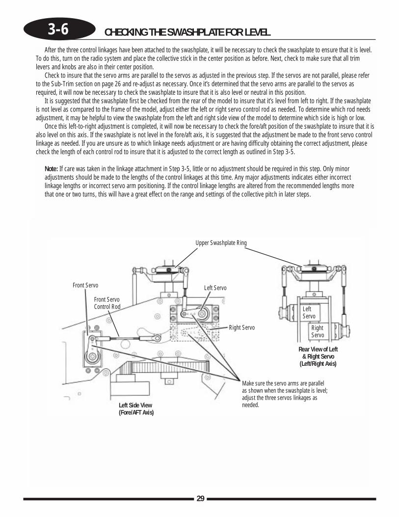
3-6 CHECKING THE SWASHPLATE FOR LEVEL
29
Upper Swashplate Ring
Left Servo
LeftServo
Right Servo RightServo
Left Side View(Fore/AFT Axis)
Rear View of Left & Right Servo
(Left/Right Axis)
Front ServoControl Rod
Make sure the servo arms are parallelas shown when the swashplate is level;adjust the three servos linkages asneeded.
Front Servo
After the three control linkages have been attached to the swashplate, it will be necessary to check the swashplate to ensure that it is level.To do this, turn on the radio system and place the collective stick in the center position as before. Next, check to make sure that all trimlevers and knobs are also in their center position.
Check to insure that the servo arms are parallel to the servos as adjusted in the previous step. If the servos are not parallel, please referto the Sub-Trim section on page 26 and re-adjust as necessary. Once it’s determined that the servo arms are parallel to the servos asrequired, it will now be necessary to check the swashplate to insure that it is also level or neutral in this position.
It is suggested that the swashplate first be checked from the rear of the model to insure that it’s level from left to right. If the swashplateis not level as compared to the frame of the model, adjust either the left or right servo control rod as needed. To determine which rod needsadjustment, it may be helpful to view the swashplate from the left and right side view of the model to determine which side is high or low.
Once this left-to-right adjustment is completed, it will now be necessary to check the fore/aft position of the swashplate to insure that it isalso level on this axis. If the swashplate is not level in the fore/aft axis, it is suggested that the adjustment be made to the front servo controllinkage as needed. If you are unsure as to which linkage needs adjustment or are having difficulty obtaining the correct adjustment, pleasecheck the length of each control rod to insure that it is adjusted to the correct length as outlined in Step 3-5.
Note: If care was taken in the linkage attachment in Step 3-5, little or no adjustment should be required in this step. Only minoradjustments should be made to the lengths of the control linkages at this time. Any major adjustments indicates either incorrectlinkage lengths or incorrect servo arm positioning. If the control linkage lengths are altered from the recommended lengths more that one or two turns, this will have a great effect on the range and settings of the collective pitch in later steps.
30
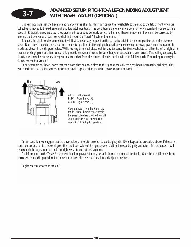
3-7 ADVANCED SETUP: PITCH-TO-AILERON MIXING ADJUSTMENTWITH TRAVEL ADJUST (OPTIONAL)
It is very possible that the travel of each servo varies slightly, which can cause the swashplate to be tilted to the left or right when thecollective is moved to the extreme high and low pitch positions. This condition is generally more common when standard type servos areused. If JR digital servos are used, the adjustment required is generally very small, if any. These variations in travel can be corrected byaltering the travel value of each servo slightly through the Travel Adjustment function.
To check the pitch-to-aileron mixing, it will first be necessary to position the collective stick in the center position as in the previoussteps. Next, move the collective stick from the center position to the high pitch position while viewing the swashplate from the rear of themodel as shown in the diagram below. While moving the swashplate, look for any tendency for the swashplate to roll to the left or right as itreaches the high pitch position. Repeat this procedure several times to be sure that your observations are correct. If no rolling tendency isfound, it will now be necessary to repeat this procedure from the center collective stick position to full low pitch. If no rolling tendency isfound, proceed to Step 3-8.
In our example, we have shown that the swashplate has been tilted to the right as the collective has been increased to full pitch. Thiswould indicate that the left servo’s maximum travel is greater than the right servo’s maximum travel.
In this condition, we suggest that the travel value for the left servo be reduced slightly (5–10%). Repeat the procedure above. If the samecondition occurs, but to a lesser degree, then the travel value of the right servo should be increased slightly and retest. In most cases, it willrequire only the adjustment of the left or right servo to correct this situation.
For information on the Travel Adjustment function, please refer to your radio instruction manual for details. Once this condition has beencorrected, repeat this procedure for the center to low collective pitch position and adjust as needed.
Beginners can proceed to step 3-9.
View is shown from the rear of themodel. Notice how in this example,the swashplate has tilted to the rightas the collective has moved fromcenter to full high pitch position.
High Low
AILE= Left Servo (C)ELEV= Front Servo (A)AUX1= Right Servo (B)
3-8 ADVANCED SETUP: PITCH-TO-ELEVATOR MIXINGADJUSTMENT WITH TRAVEL ADJUST (OPTIONAL)
31
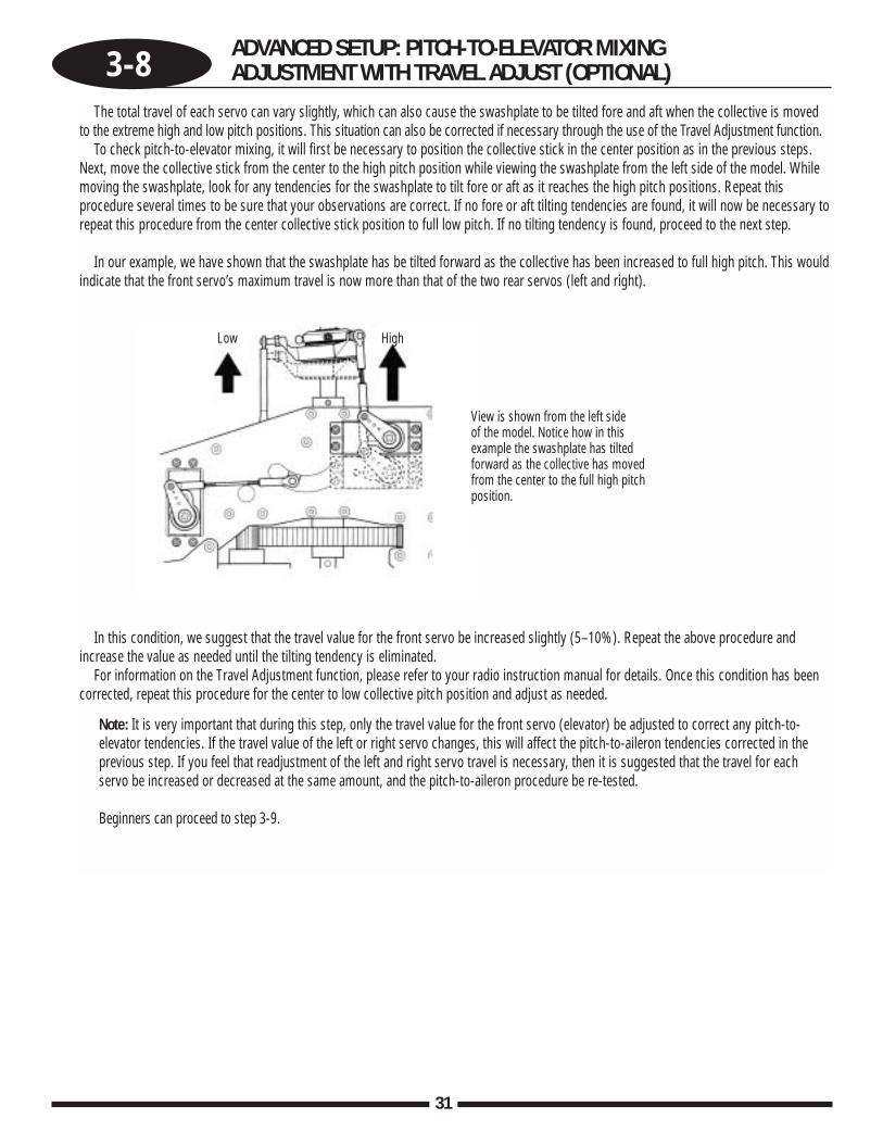
The total travel of each servo can vary slightly, which can also cause the swashplate to be tilted fore and aft when the collective is movedto the extreme high and low pitch positions. This situation can also be corrected if necessary through the use of the Travel Adjustment function.
To check pitch-to-elevator mixing, it will first be necessary to position the collective stick in the center position as in the previous steps.Next, move the collective stick from the center to the high pitch position while viewing the swashplate from the left side of the model. Whilemoving the swashplate, look for any tendencies for the swashplate to tilt fore or aft as it reaches the high pitch positions. Repeat thisprocedure several times to be sure that your observations are correct. If no fore or aft tilting tendencies are found, it will now be necessary torepeat this procedure from the center collective stick position to full low pitch. If no tilting tendency is found, proceed to the next step.
In our example, we have shown that the swashplate has be tilted forward as the collective has been increased to full high pitch. This wouldindicate that the front servo’s maximum travel is now more than that of the two rear servos (left and right).
In this condition, we suggest that the travel value for the front servo be increased slightly (5–10%). Repeat the above procedure andincrease the value as needed until the tilting tendency is eliminated.
For information on the Travel Adjustment function, please refer to your radio instruction manual for details. Once this condition has beencorrected, repeat this procedure for the center to low collective pitch position and adjust as needed.
Note: It is very important that during this step, only the travel value for the front servo (elevator) be adjusted to correct any pitch-to-elevator tendencies. If the travel value of the left or right servo changes, this will affect the pitch-to-aileron tendencies corrected in theprevious step. If you feel that readjustment of the left and right servo travel is necessary, then it is suggested that the travel for eachservo be increased or decreased at the same amount, and the pitch-to-aileron procedure be re-tested.
Beginners can proceed to step 3-9.
View is shown from the left side of the model. Notice how in thisexample the swashplate has tiltedforward as the collective has movedfrom the center to the full high pitchposition.
HighLow
32
3-9 TAIL CONTROL ROD SERVO CONNECTION
Use Blue Threadlock
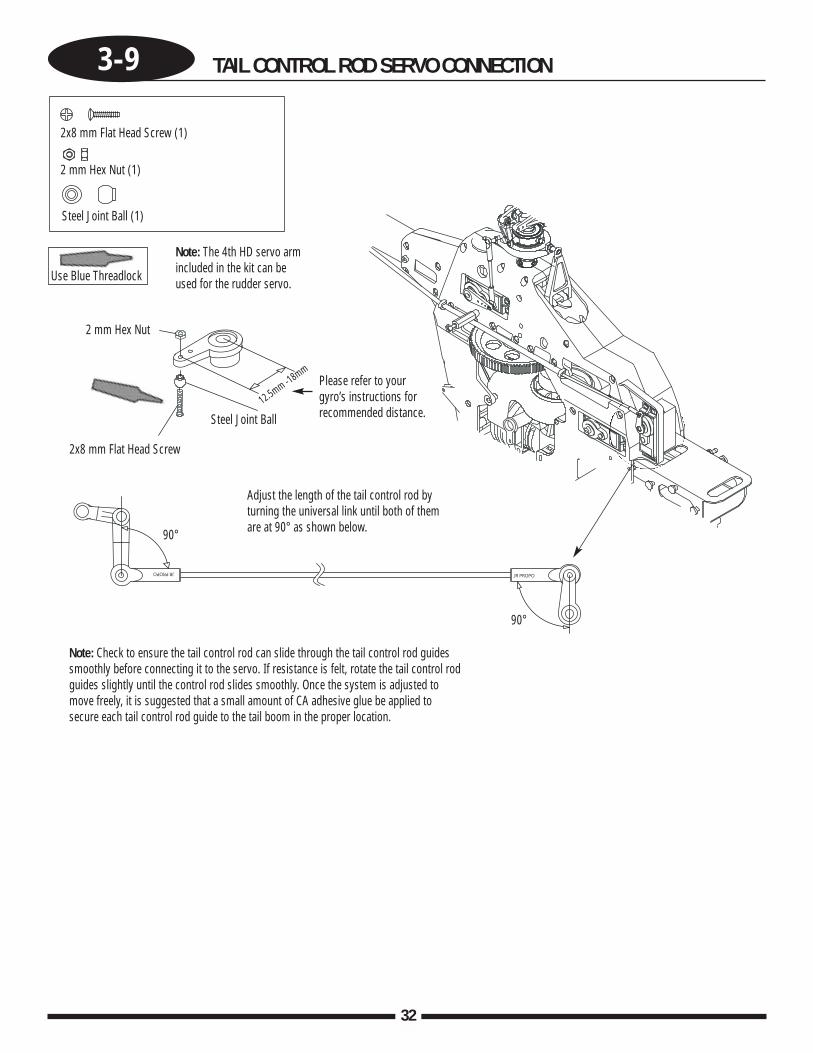
Note: Check to ensure the tail control rod can slide through the tail control rod guidessmoothly before connecting it to the servo. If resistance is felt, rotate the tail control rodguides slightly until the control rod slides smoothly. Once the system is adjusted tomove freely, it is suggested that a small amount of CA adhesive glue be applied tosecure each tail control rod guide to the tail boom in the proper location.
Adjust the length of the tail control rod byturning the universal link until both of themare at 90° as shown below.
Please refer to yourgyro’s instructions forrecommended distance.
Note: The 4th HD servo armincluded in the kit can beused for the rudder servo.
2x8 mm Flat Head Screw (1)
2 mm Hex Nut (1)
Steel Joint Ball (1)
2 mm Hex Nut
Steel Joint Ball12.5mm -18mm
2x8 mm Flat Head Screw
90°
90°
3-10 THROTTLE LINKAGE INSTALLATION
33
Use Blue Threadlock
High
Low
Throttle
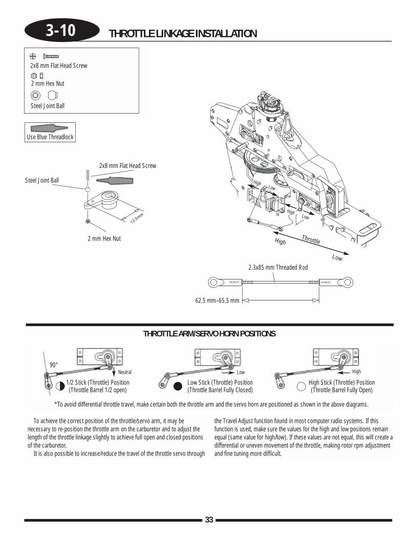
THROTTLE ARM/SERVO HORN POSITIONS
*To avoid differential throttle travel, make certain both the throttle arm and the servo horn are positioned as shown in the above diagrams.
1/2 Stick (Throttle) Position(Throttle Barrel 1/2 open)
Low Stick (Throttle) Position(Throttle Barrel Fully Closed)
High Stick (Throttle) Position(Throttle Barrel Fully Open)
To achieve the correct position of the throttle/servo arm, it may benecessary to re-position the throttle arm on the carburetor and to adjust thelength of the throttle linkage slightly to achieve full open and closed positionsof the carburetor.
It is also possible to increase/reduce the travel of the throttle servo through
the Travel Adjust function found in most computer radio systems. If thisfunction is used, make sure the values for the high and low positions remainequal (same value for high/low). If these values are not equal, this will create adifferential or uneven movement of the throttle, making rotor rpm adjustmentand fine tuning more difficult.
90°
2x8 mm Flat Head Screw
2x8 mm Flat Head Screw
2 mm Hex Nut
2 mm Hex Nut
Steel Joint Ball
Steel Joint Ball
2.3x85 mm Threaded Rod
62.5 mm–65.5 mm
HighLow
HighLow
Neutral Low High
34
4-1 BODY ASSEMBLY/CANOPY ATTACHMENT
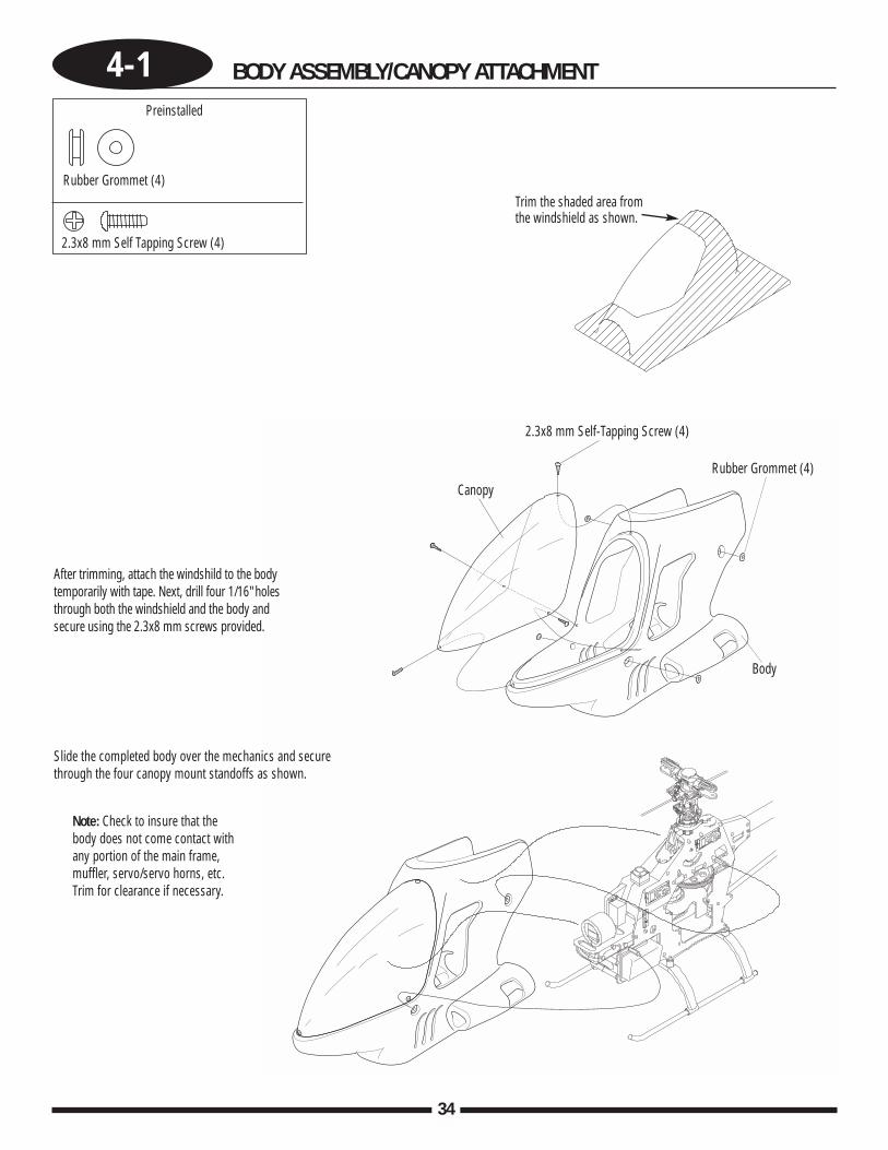
After trimming, attach the windshild to the bodytemporarily with tape. Next, drill four 1/16" holesthrough both the windshield and the body andsecure using the 2.3x8 mm screws provided.
Slide the completed body over the mechanics and securethrough the four canopy mount standoffs as shown.
Note: Check to insure that thebody does not come contact withany portion of the main frame,muffler, servo/servo horns, etc.Trim for clearance if necessary.
Rubber Grommet (4)
Preinstalled
Rubber Grommet (4)
Body
Canopy
2.3x8 mm Self Tapping Screw (4)
2.3x8 mm Self-Tapping Screw (4)
Trim the shaded area fromthe windshield as shown.
35
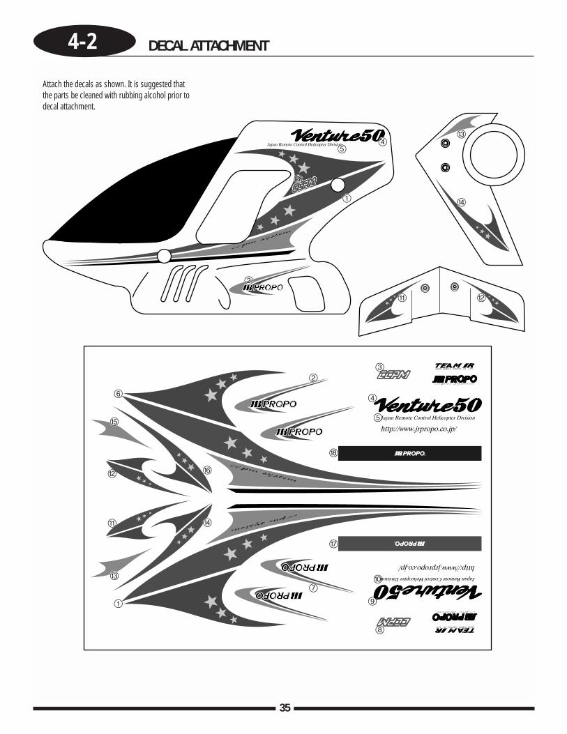
4-2 DECAL ATTACHMENT
Attach the decals as shown. It is suggested thatthe parts be cleaned with rubbing alcohol prior todecal attachment.
36
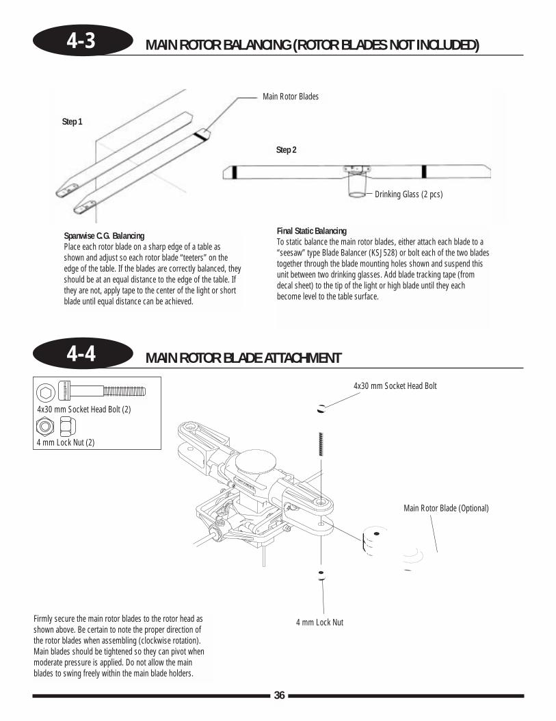
4-3 MAIN ROTOR BALANCING (ROTOR BLADES NOT INCLUDED)
4-4 MAIN ROTOR BLADE ATTACHMENT
4 mm Lock Nut (2)
4 mm Lock Nut Firmly secure the main rotor blades to the rotor head asshown above. Be certain to note the proper direction ofthe rotor blades when assembling (clockwise rotation).Main blades should be tightened so they can pivot whenmoderate pressure is applied. Do not allow the mainblades to swing freely within the main blade holders.
Spanwise C.G. BalancingPlace each rotor blade on a sharp edge of a table asshown and adjust so each rotor blade “teeters” on theedge of the table. If the blades are correctly balanced, theyshould be at an equal distance to the edge of the table. Ifthey are not, apply tape to the center of the light or shortblade until equal distance can be achieved.
Final Static BalancingTo static balance the main rotor blades, either attach each blade to a“seesaw” type Blade Balancer (KSJ528) or bolt each of the two bladestogether through the blade mounting holes shown and suspend thisunit between two drinking glasses. Add blade tracking tape (fromdecal sheet) to the tip of the light or high blade until they eachbecome level to the table surface.
Step 1
Step 2
Drinking Glass (2 pcs)
Main Rotor Blades
4x30 mm Socket Head Bolt (2)
4x30 mm Socket Head Bolt
Main Rotor Blade (Optional)
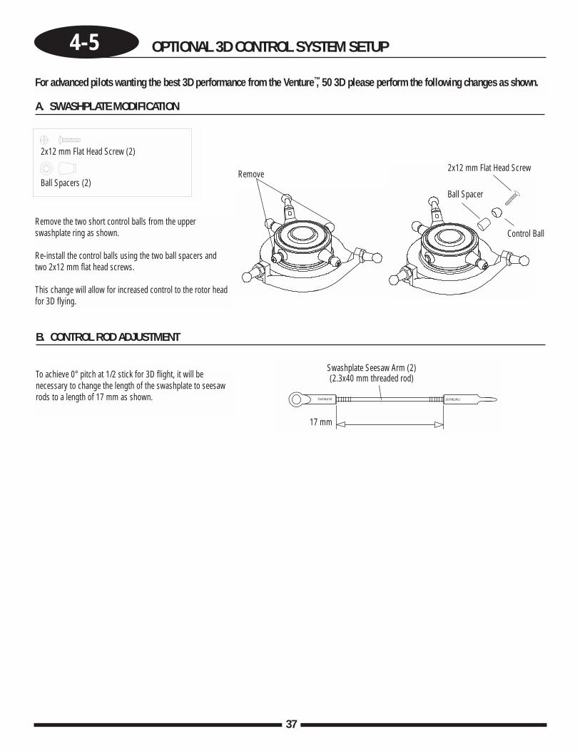
4-5 OPTIONAL 3D CONTROL SYSTEM SETUP
37
For advanced pilots wanting the best 3D performance from the Venture™, 50 3D please perform the following changes as shown.
Remove the two short control balls from the upperswashplate ring as shown.
Re-install the control balls using the two ball spacers and two 2x12 mm flat head screws.
This change will allow for increased control to the rotor headfor 3D flying.
To achieve 0° pitch at 1/2 stick for 3D flight, it will benecessary to change the length of the swashplate to seesawrods to a length of 17 mm as shown.
A. SWASHPLATE MODIFICATION
Remove
B. CONTROL ROD ADJUSTMENT
2x12 mm Flat Head Screw (2)
Ball Spacers (2)
Swashplate Seesaw Arm (2)(2.3x40 mm threaded rod)
17 mm
Ball Spacer
Control Ball
2x12 mm Flat Head Screw
38
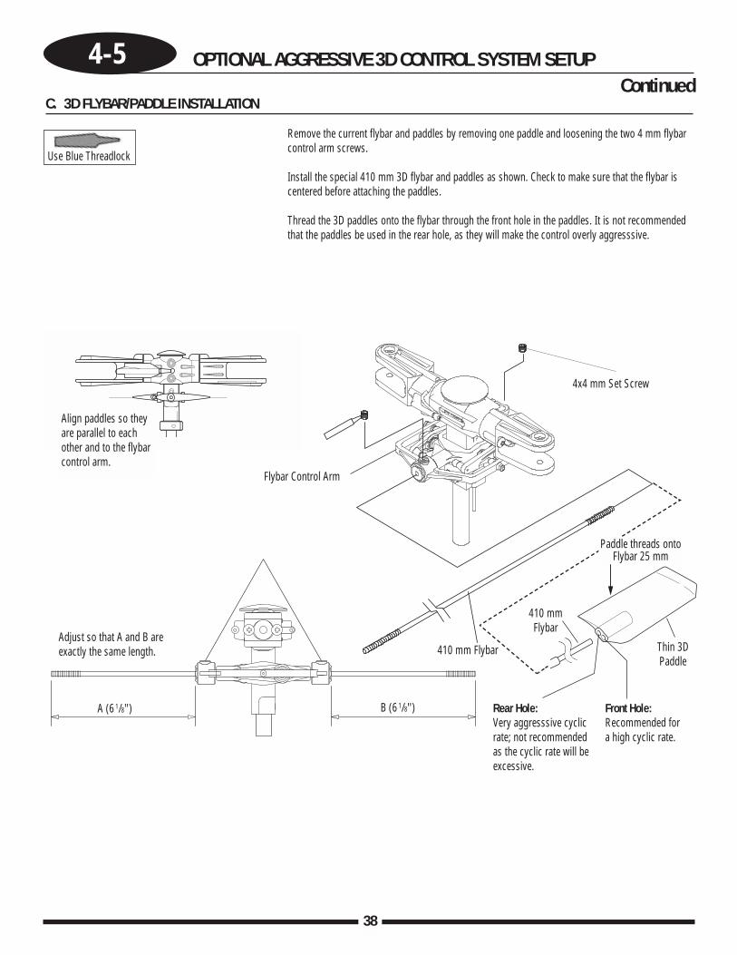
4-5 OPTIONAL AGGRESSIVE 3D CONTROL SYSTEM SETUP
C. 3D FLYBAR/PADDLE INSTALLATION
Remove the current flybar and paddles by removing one paddle and loosening the two 4 mm flybarcontrol arm screws.
Install the special 410 mm 3D flybar and paddles as shown. Check to make sure that the flybar iscentered before attaching the paddles.
Thread the 3D paddles onto the flybar through the front hole in the paddles. It is not recommendedthat the paddles be used in the rear hole, as they will make the control overly aggresssive.
Use Blue Threadlock
Align paddles so theyare parallel to eachother and to the flybarcontrol arm.
Flybar Control Arm
Adjust so that A and B areexactly the same length.
Rear Hole:Very aggresssive cyclicrate; not recommendedas the cyclic rate will beexcessive.
Front Hole:Recommended fora high cyclic rate.
A (61/8'') B (61/8'')
410 mm Flybar
Paddle threads ontoFlybar 25 mm
Thin 3DPaddle
4x4 mm Set Screw
410 mm Flybar
Continued
39
Factory Preset
Factory Preset
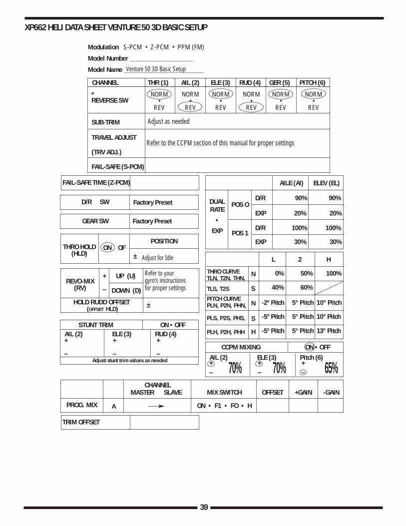
XP662 HELI DATA SHEET VENTURE 50 3D BASIC SETUP
D/R 90% 90%
EXP 20% 20%
D/R 100% 100%
EXP 30% 30%
TRIM OFFSET
CHANNEL THR (1) AIL (2) ELE (3) RUD (4) GER (5) PITCH (6)
NORM NORM NORM NORM NORM NORM• • • • • •
REV REV REV REV REV REV
SUB-TRIM
TRAVEL ADJUST
(TRV ADJ.)
FAIL-SAFE (S-PCM)
REVERSE SW*
FAIL-SAFE TIME (Z-PCM) AILE (AI) ELEV (EL)
POS O
POS 1
L 2 H
N
S
N
S
H
THRO CURVE TLN, T2N, THN,
TLS, T2S
PITCH CURVEPLN, P2N, PHN,
PLS, P2S, PHS,
PLH, P2H, PHH
0% 50% 100%
40% 60%
-2° Pitch 5° Pitch 10° Pitch
-5° Pitch 5° Pitch 10° Pitch
-5° Pitch 5° Pitch 13° Pitch
DUAL RATE
•
EXP
D/R SW
GEAR SW
REVO-MIX(RV)
HOLD RUDD OFFSET(OFFSET HLD)
UP (U)
±
DOWN (D)
+
–
THRO HOLD(HLD)
ON OF
PROG. MIX A
CHANNELMASTER SLAVE MIX SWITCH OFFSET +GAIN -GAIN
ON • F1 • FO • H
POSITION
±
Modulation S-PCM • Z-PCM • PPM (FM)
Model Number ___________________
Model Name ________________________
AIL (2) ELE (3) Pitch (6)
CCPM MIXING ON • OFF
+– 70%70% 65%+
–+–
AIL (2) ELE (3) RUD (4)STUNT TRIM ON • OFF
+
–
+
–
+
–Adjust stunt trim values as needed
Venture 50 3D Basic Setup
Adjust as needed
Adjust for Idle
Refer to yourgyro’s instructionsfor proper settings
Refer to the CCPM section of this manual for proper settings
40
Factory Preset
Factory Preset
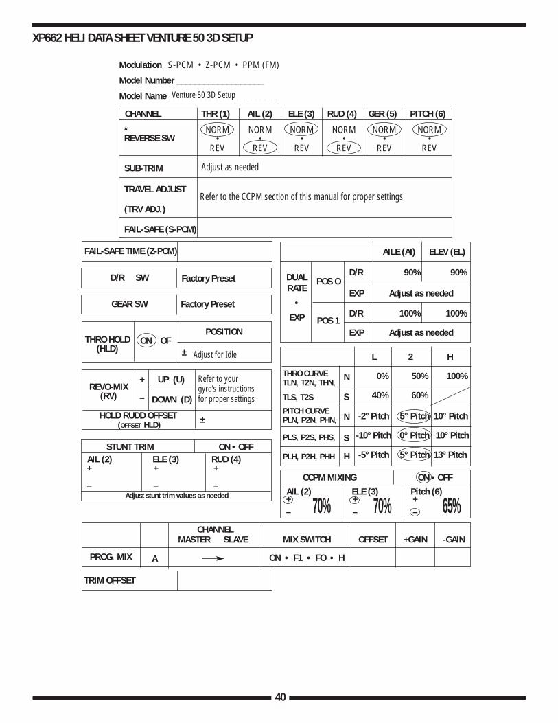
XP662 HELI DATA SHEET VENTURE 50 3D SETUP
D/R 90% 90%
EXP Adjust as needed
D/R 100% 100%
EXP Adjust as needed
TRIM OFFSET
CHANNEL THR (1) AIL (2) ELE (3) RUD (4) GER (5) PITCH (6)
NORM NORM NORM NORM NORM NORM• • • • • •
REV REV REV REV REV REV
SUB-TRIM
TRAVEL ADJUST
(TRV ADJ.)
FAIL-SAFE (S-PCM)
REVERSE SW*
FAIL-SAFE TIME (Z-PCM) AILE (AI) ELEV (EL)
POS O
POS 1
L 2 H
N
S
N
S
H
THRO CURVE TLN, T2N, THN,
TLS, T2S
PITCH CURVEPLN, P2N, PHN,
PLS, P2S, PHS,
PLH, P2H, PHH
0% 50% 100%
40% 60%
-2° Pitch 5° Pitch 10° Pitch
-10° Pitch 0° Pitch 10° Pitch
-5° Pitch 5° Pitch 13° Pitch
DUAL RATE
•
EXP
D/R SW
GEAR SW
REVO-MIX(RV)
HOLD RUDD OFFSET(OFFSET HLD)
UP (U)
±
DOWN (D)
+
–
THRO HOLD(HLD)
ON OF
PROG. MIX A
CHANNELMASTER SLAVE MIX SWITCH OFFSET +GAIN -GAIN
ON • F1 • FO • H
POSITION
±
Modulation S-PCM • Z-PCM • PPM (FM)
Model Number ___________________
Model Name ________________________
AIL (2) ELE (3) Pitch (6)
CCPM MIXING ON • OFF
+– 70%70% 65%+
–+–
AIL (2) ELE (3) RUD (4)STUNT TRIM ON • OFF
+
–
+
–
+
–Adjust stunt trim values as needed
Venture 50 3D Setup
Adjust as needed
Adjust for Idle
Refer to the CCPM section of this manual for proper settings
Refer to yourgyro’s instructionsfor proper settings
41
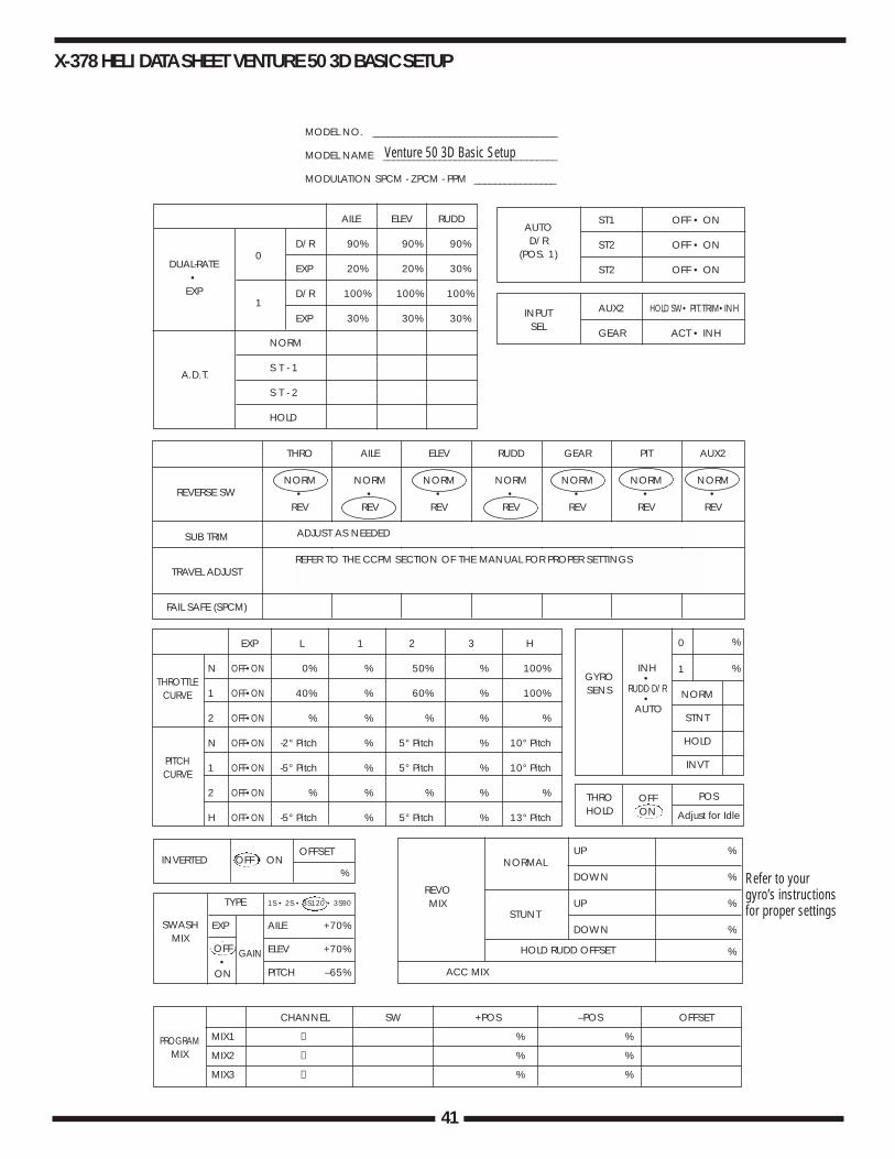
X-378 HELI DATA SHEET VENTURE 50 3D BASIC SETUP
EXP L 1 2 3 H
N OFF•ON 0% % 50% % 100%
1 OFF•ON 40% % 60% % 100%
2 OFF•ON % % % % %
N OFF•ON -2° Pitch % 5° Pitch % 10° Pitch
1 OFF•ON -5° Pitch % 5° Pitch % 10° Pitch
2 OFF•ON % % % % %
H OFF•ON -5° Pitch % 5° Pitch % 13° Pitch
1
MODEL NO. ____________________________________
MODEL NAME __________________________________
MODULATION SPCM - ZPCM - PPM ________________
AILE ELEV RUDD
D/R 90% 90% 90%
EXP 20% 20% 30%
D/R 100% 100% 100%
EXP 30% 30% 30%
NORM
S T - 1
S T - 2
HOLD
0
0 %
%
REVOMIX
ACC MIX
HOLD RUDD OFFSET
NORMAL
NORM
STNT
HOLD
INVT
UP %
DOWN %
UP %
DOWN %
%
GYROSENS
THROHOLD
OFFON
POS
Adjust for Idle
INH•
RUDD D/R•
AUTO
STUNT
PROGRAMMIX
THROTTLECURVE
PITCHCURVE
CHANNEL SW +POS –POS OFFSET
MIX1 → % %
MIX2 → % %
MIX3 → % %
REVERSE SW
SUB TRIM
TRAVEL ADJUST
FAIL SAFE (SPCM)
THRO AILE ELEV RUDD GEAR PIT AUX2
NORM NORM NORM NORM NORM NORM NORM• • • • • • •
REV REV REV REV REV REV REV
DUAL-RATE•
EXP
A.D.T.
AUTOD/R
(POS. 1)
ST1 OFF • ON
ST2 OFF • ON
ST2 OFF • ON
AUX2 HOLD SW• PIT.TRIM•INH
GEAR ACT • INH
INPUTSEL
1
%
OFFSETINVERTED OFF • ON
TYPE 1S • 2S • 3S120 • 3S90
EXP AILE +70%
ELEV +70%
PITCH –65%
SWASHMIX
OFF•
ON
GAIN
Venture 50 3D Basic Setup
ADJUST AS NEEDED
REFER TO THE CCPM SECTION OF THE MANUAL FOR PROPER SETTINGS
Refer to yourgyro’s instructionsfor proper settings
42
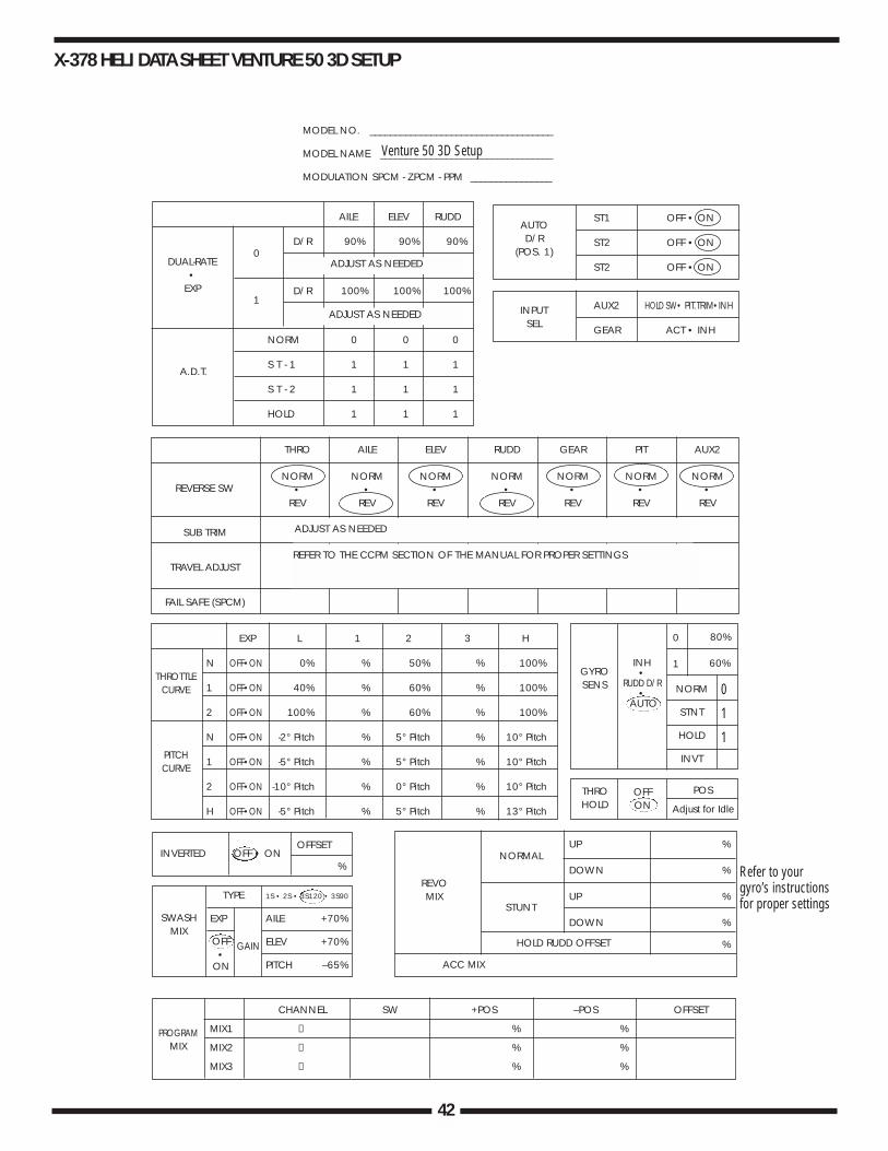
EXP L 1 2 3 H
N OFF•ON 0% % 50% % 100%
1 OFF•ON 40% % 60% % 100%
2 OFF•ON 100% % 60% % 100%
N OFF•ON -2° Pitch % 5° Pitch % 10° Pitch
1 OFF•ON -5° Pitch % 5° Pitch % 10° Pitch
2 OFF•ON -10° Pitch % 0° Pitch % 10° Pitch
H OFF•ON -5° Pitch % 5° Pitch % 13° Pitch
1
MODEL NO. ____________________________________
MODEL NAME __________________________________
MODULATION SPCM - ZPCM - PPM ________________
AILE ELEV RUDD
D/R 90% 90% 90%
D/R 100% 100% 100%
NORM 0 0 0
S T - 1 1 1 1
S T - 2 1 1 1
HOLD 1 1 1
0
0 80%
60%
REVOMIX
ACC MIX
HOLD RUDD OFFSET
NORMAL
NORM
STNT
HOLD
INVT
UP %
DOWN %
UP %
DOWN %
%
GYROSENS
THROHOLD
OFFON
POS
Adjust for Idle
INH•
RUDD D/R•
AUTO
STUNT
PROGRAMMIX
THROTTLECURVE
PITCHCURVE
CHANNEL SW +POS –POS OFFSET
MIX1 → % %
MIX2 → % %
MIX3 → % %
REVERSE SW
SUB TRIM
TRAVEL ADJUST
FAIL SAFE (SPCM)
THRO AILE ELEV RUDD GEAR PIT AUX2
NORM NORM NORM NORM NORM NORM NORM• • • • • • •
REV REV REV REV REV REV REV
DUAL-RATE•
EXP
ADJUST AS NEEDED
ADJUST AS NEEDED
A.D.T.
AUTOD/R
(POS. 1)
ST1 OFF • ON
ST2 OFF • ON
ST2 OFF • ON
AUX2 HOLD SW• PIT.TRIM•INH
GEAR ACT • INH
INPUTSEL
1
%
OFFSETINVERTED OFF • ON
TYPE 1S • 2S • 3S120 • 3S90
EXP AILE +70%
ELEV +70%
PITCH –65%
SWASHMIX
0
1
1
OFF•
ON
GAIN
Venture 50 3D Setup
ADJUST AS NEEDED
REFER TO THE CCPM SECTION OF THE MANUAL FOR PROPER SETTINGS
Refer to yourgyro’s instructionsfor proper settings
X-378 HELI DATA SHEET VENTURE 50 3D SETUP

43
XP8103 HELI DATA SHEET VENTURE 50 3D BASIC SETUP
EXP L 1 2 3 H
N OFF•ON 0% 30% 50% 70% 100%
1 OFF•ON 40% 50% 60% 80% 100%
2 OFF•ON
N OFF•ON -2° pitch % 5° pitch % 10° pitch
1 OFF•ON -5° pitch % 5° pitch % 10° pitch
2 OFF•ON % % % % %
H OFF•ON -5° pitch % 5° pitch % 13° pitch
1
MODEL NO. ____________________________________
MODEL NAME __________________________________
MODULATION SPCM - ZPCM - PPM ________________
AILE ELEV RUDD
D/R 90% 90% 90%
EXP
D/R 100% 100% 100%
EXP
0
0 80%
60%
Set for idle
Adjust asneeded
POS
OFFSET
REVOMIX
ACC MIX
NORMAL
NORM
STNT
HOLD
INVT
UP %
DOWN %
UP %
DOWN %
%
GYROSENS
INH•
RUDD D/R•
AUTO
STUNT
PROGRAMMIX
THROTTLECURVE
PITCHCURVE
THRO HOLD INH • ACT
THRO HOLD INH • ACT
CHANNEL SW EXP L 1 2 3 H
MIX1 → OFF-ON
MIX2 → OFF-ON
+POS -POS OFFSET
MIX3 → % %
REVERSE SW
SUB TRIM
TRAVEL ADJUST
FAIL SAFE (SPCM)
THRO AILE ELEV RUDD GEAR PIT AUX2 AUX3
NORM NORM NORM NORM NORM NORM NORM NORM• • • • • • • •
REV REV REV REV REV REV REV REV
DUAL-RATE•
EXP
AUTOD/R
(POS. 1)
ST1 INH • ACT
ST2 INH • ACT
ST2 INH • ACT
AUX2 HOLD SW• PIT.TRIM•INH
GEAR ACT • INH
INPUTSEL
1
Adjust as needed
Adjust as needed
Adjust as needed
Refer to the CCPM section of this manual for proper settings
Optional
Refer to gyrogain section forsettings
Refer to yourgyro’s instructionsfor proper settings
0
1
11
Swash 1 Servo Norm 2 Servo 180° 3 Servo 120° 4 Servo 90°Type Aile Elev Pit
Exp + + +Act•INH - 70% - 70% - 65%
Venture 50 3D Setup
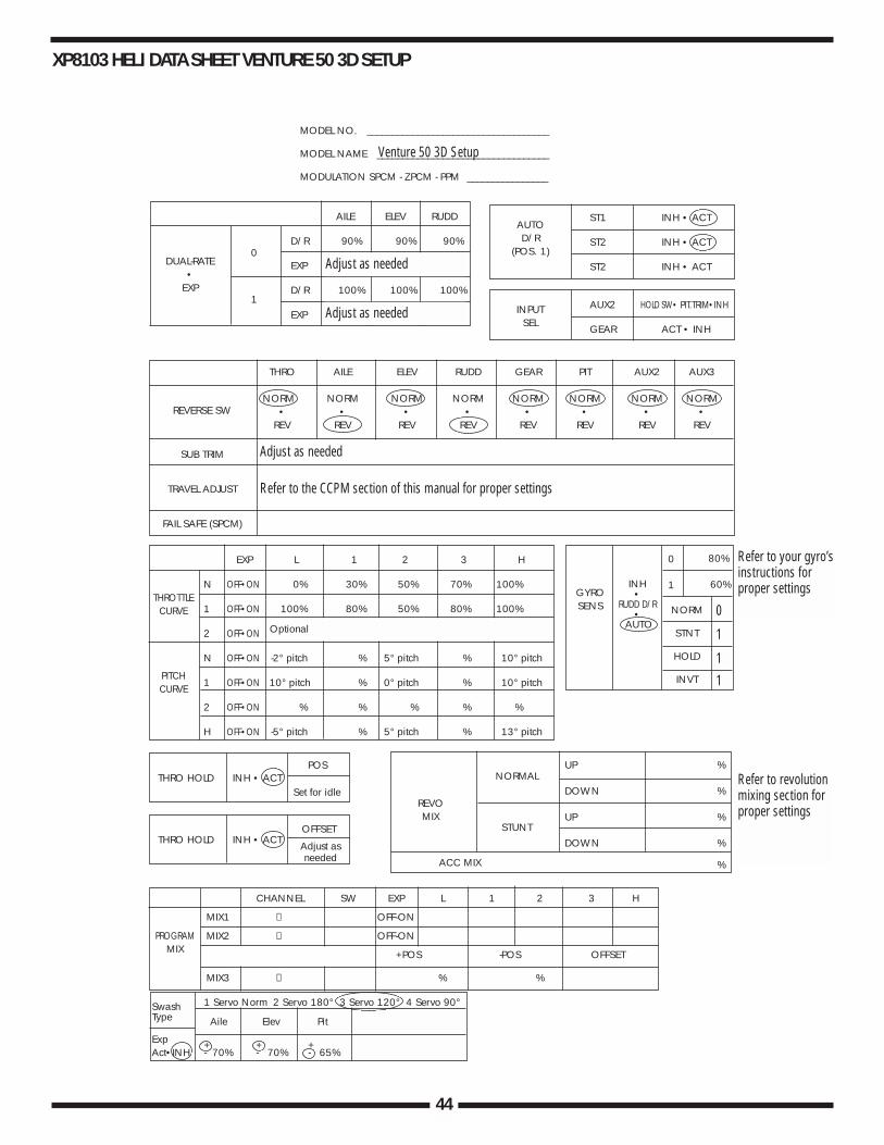
44
XP8103 HELI DATA SHEET VENTURE 50 3D SETUP
EXP L 1 2 3 H
N OFF•ON 0% 30% 50% 70% 100%
1 OFF•ON 100% 80% 50% 80% 100%
2 OFF•ON
N OFF•ON -2° pitch % 5° pitch % 10° pitch
1 OFF•ON 10° pitch % 0° pitch % 10° pitch
2 OFF•ON % % % % %
H OFF•ON -5° pitch % 5° pitch % 13° pitch
1
MODEL NO. ____________________________________
MODEL NAME __________________________________
MODULATION SPCM - ZPCM - PPM ________________
AILE ELEV RUDD
D/R 90% 90% 90%
EXP
D/R 100% 100% 100%
EXP
0
0 80%
60%
Set for idle
Adjust asneeded
POS
OFFSET
REVOMIX
ACC MIX
NORMAL
NORM
STNT
HOLD
INVT
UP %
DOWN %
UP %
DOWN %
%
GYROSENS
INH•
RUDD D/R•
AUTO
STUNT
PROGRAMMIX
THROTTLECURVE
PITCHCURVE
THRO HOLD INH • ACT
THRO HOLD INH • ACT
CHANNEL SW EXP L 1 2 3 H
MIX1 → OFF-ON
MIX2 → OFF-ON
+POS -POS OFFSET
MIX3 → % %
REVERSE SW
SUB TRIM
TRAVEL ADJUST
FAIL SAFE (SPCM)
THRO AILE ELEV RUDD GEAR PIT AUX2 AUX3
NORM NORM NORM NORM NORM NORM NORM NORM• • • • • • • •
REV REV REV REV REV REV REV REV
DUAL-RATE•
EXP
AUTOD/R
(POS. 1)
ST1 INH • ACT
ST2 INH • ACT
ST2 INH • ACT
AUX2 HOLD SW• PIT.TRIM•INH
GEAR ACT • INH
INPUTSEL
1
Adjust as needed
Adjust as needed
Adjust as needed
Refer to the CCPM section of this manual for proper settings
Optional
Refer to your gyro’sinstructions forproper settings
Refer to revolutionmixing section forproper settings
0
1
11
Swash 1 Servo Norm 2 Servo 180° 3 Servo 120° 4 Servo 90°Type Aile Elev Pit
Exp + + +Act•INH - 70% - 70% - 65%
Venture 50 3D Setup
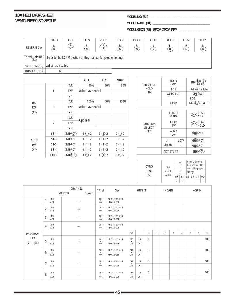
45
10X HELI DATA SHEET VENTURE 50 3D SETUP
THRO AILE ELEV RUDD GEAR PITCH AUX2 AUX3 AUX4 AUX5
R R R R R R R R R RN N N N N N N N N N
%
REVERSE SW
TRAVEL ADJUST(12)
SUB-TRIM (15)
TRIM RATE (83)
PROGRAMMIX
(51) - (58)
AILE ELEV RUDD
D/R 90% 90% 90%
0 EXP
TYPE
D/R 100% 100% 100%
1 EXP
TYPE
D/R % % %
2 EXP % % %
TYPE
ST-1 INH•ACT 0 • 1 • 2 0 • 1 • 2 0 • 1 • 2
ST-2 INH•ACT 0 • 1 • 2 0 • 1 • 2 0 • 1 • 2
ST-3 INH•ACT 0 • 1 • 2 0 • 1 • 2 0 • 1 • 2
ST-4 INH•ACT 0 • 1 • 2 0 • 1 • 2 0 • 1 • 2
HOLD INH•ACT 0 • 1 • 2 0 • 1 • 2 0 • 1 • 2
D/REXP(13)
AUTOD/R(23)
HOLD INH•HOLD
SW GEAR
POS Adjust for IdleAUTO CUT INH•ACT
POSDelay 1/4 1/2 3/4 1
FLIGHT INH•GEAR
EXTRA AILE
GEAR INH•GEAR
SW HOLD
AUX2 INH•ACTSW
PIT. LOW INH•ACTLEVER HI INH•ACT
ADT STUNT INH•ACT
THROTTLEHOLD(16)
INH•
AUX 3•
AUTO
0
12
NR S1 S2 S3 S4 HD
0 1 1
GYROSENS(44)
FUNCTIONSELECT
(17)
CHANNEL TRIM SW OFFSET +GAIN –GAINMASTER SLAVE
INH OFF NR•S1•S2•S3•S41 • → •ACT ON HD•AX2•GER
INH OFF NR•S1•S2•S3•S42 • → •ACT ON HD•AX2•GER
INH OFF NR•S1•S2•S3•S43 • → •ACT ON HD•AX2•GER
INH OFF NR•S1•S2•S3•S44 • → •ACT ON HD•AX2•GER
EXP L 1 2 3 4 5 6 H
INH OFF NR•S1•S2•S3•S4 OFF IN 0 1005 • → • •
ACT ON HD•AX2•GER ON OUT
INH OFF NR•S1•S2•S3•S4 OFF IN 0 1006 • → • •
ACT ON HD•AX2•GER ON OUT
INH OFF NR•S1•S2•S3•S4 OFF IN 0 1007 • → • •
ACT ON HD•AX2•GER ON OUT
INH OFF NR•S1•S2•S3•S4 OFF IN 0 1008 • → • •
ACT ON HD•AX2•GER ON OUT
MODEL NO. (84) _____________________________________
MODEL NAME (81) ___________________________________
MODULATION (85) SPCM-ZPCM-PPM ___________________
Refer to the CCPM section of this manual for proper settings
Adjust as needed
Adjust as needed
Adjust as needed
Optional
Refer to the GyroGain Section of thismanual for propersettings
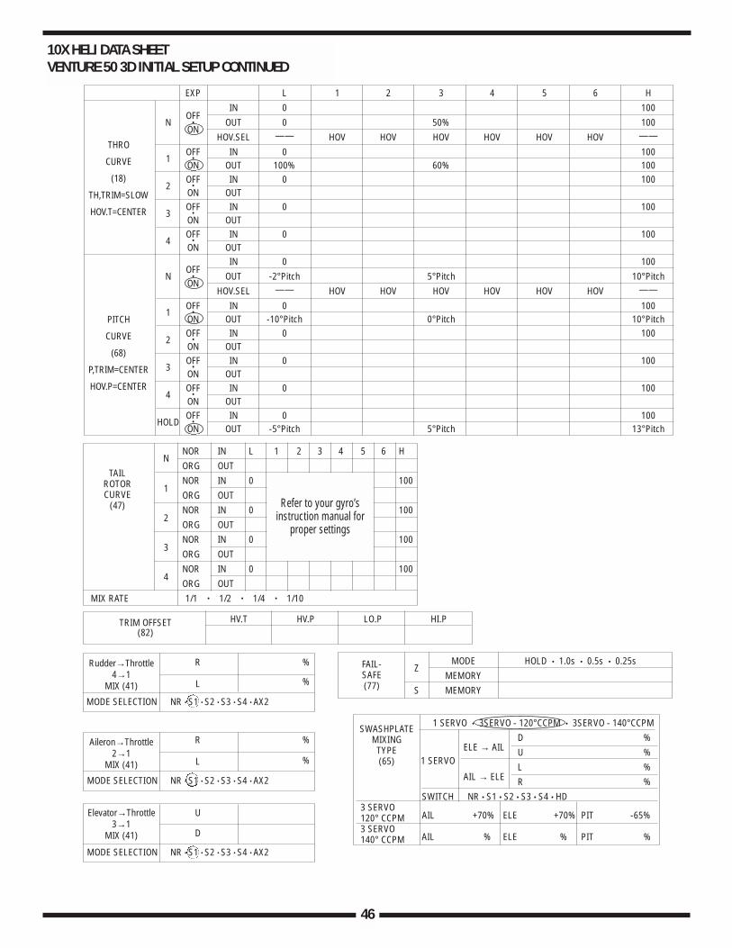
46
TRIM OFFSET HV.T HV.P LO.P HI.P(82)
NNOR IN L 1 2 3 4 5 6 HORG OUT
1NOR IN 0 100ORG OUT
2NOR IN 0 100ORG OUT
3NOR IN 0 100ORG OUT
4NOR IN 0 100ORG OUT
MIX RATE 1/1 • 1/2 • 1/4 • 1/10
TAILROTORCURVE
(47)
ZMODE HOLD • 1.0s • 0.5s • 0.25s
MEMORYS MEMORY
FAIL-SAFE(77)
1 SERVO • 3SERVO - 120°CCPM • 3SERVO - 140°CCPM
ELE → AILD %
1 SERVOU %
AIL → ELEL %R %
SWITCH NR • S1 • S2 • S3 • S4 • HD3 SERVO
AIL +70% ELE +70% PIT -65%120° CCPM3 SERVO
AIL % ELE % PIT %140° CCPM
SWASHPLATEMIXINGTYPE(65)
R %
L %
MODE SELECTION NR • S1 • S2 • S3 • S4 • AX2
Rudder→Throttle4→1
MIX (41)
R %
L %
MODE SELECTION NR • S1 • S2 • S3 • S4 • AX2
Aileron→Throttle2→1
MIX (41)
U
D
MODE SELECTION NR • S1 • S2 • S3 • S4 • AX2
Elevator→Throttle3→1
MIX (41)
10X HELI DATA SHEET VENTURE 50 3D INITIAL SETUP CONTINUED
EXP L 1 2 3 4 5 6 H
OFFIN 0 100
N • OUT 0 50% 100ON
HOV.SEL —— HOV HOV HOV HOV HOV HOV ——
1OFF IN 0 100
•ON OUT 100% 60% 100
2OFF IN 0 100
•ON OUT
3OFF IN 0 100
•ON OUT
4OFF IN 0 100
•ON OUT
OFFIN 0 100
N • OUT -2°Pitch 5°Pitch 10°PitchON
HOV.SEL —— HOV HOV HOV HOV HOV HOV ——
1OFF IN 0 100
•ON OUT -10°Pitch 0°Pitch 10°Pitch
2OFF IN 0 100
•ON OUT
3OFF IN 0 100
•ON OUT
4OFF IN 0 100
•ON OUT
HOLDOFF IN 0 100
•ON OUT -5°Pitch 5°Pitch 13°Pitch
THRO
CURVE
(18)
TH,TRIM=SLOW
HOV.T=CENTER
PITCH
CURVE
(68)
P,TRIM=CENTER
HOV.P=CENTER
Refer to your gyro’sinstruction manual for
proper settings
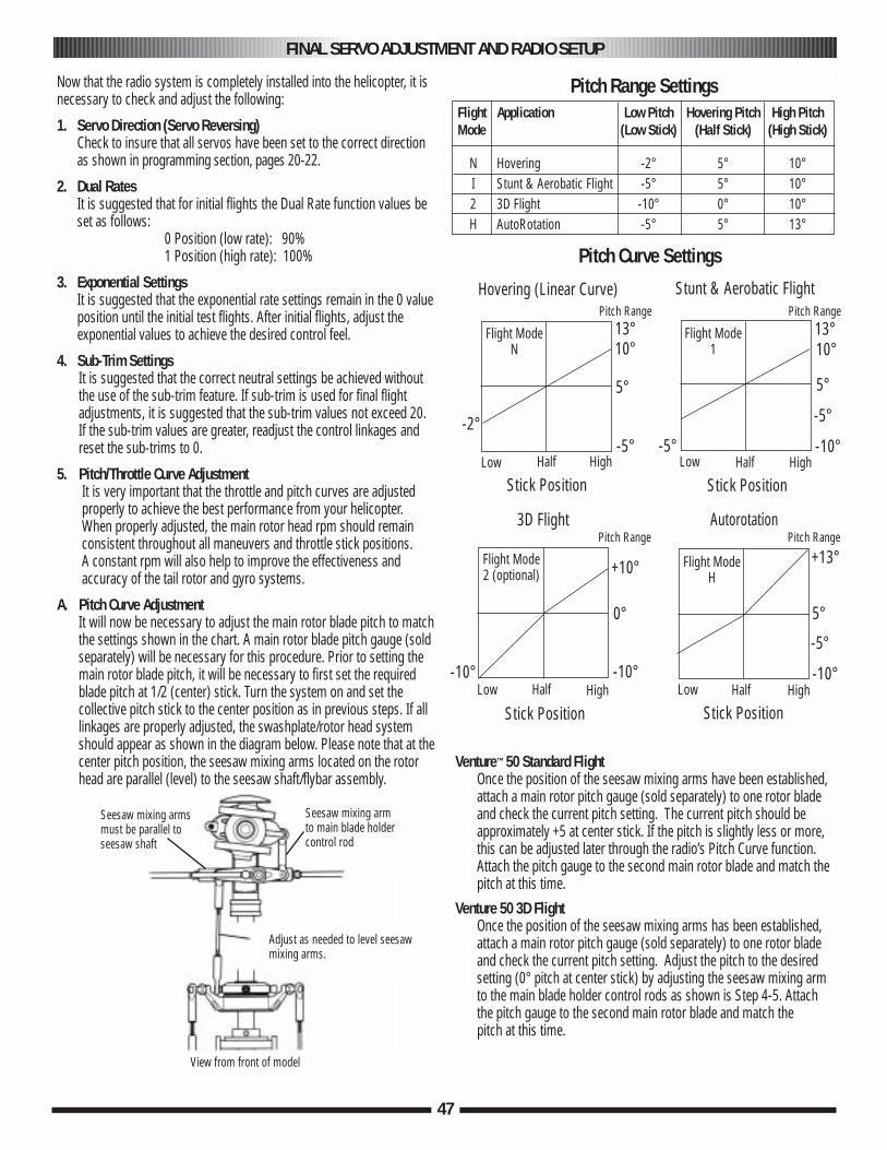
47
FINAL SERVO ADJUSTMENT AND RADIO SETUP
Now that the radio system is completely installed into the helicopter, it isnecessary to check and adjust the following:
1. Servo Direction (Servo Reversing)Check to insure that all servos have been set to the correct directionas shown in programming section, pages 20-22.
2. Dual RatesIt is suggested that for initial flights the Dual Rate function values beset as follows:
0 Position (low rate): 90%1 Position (high rate): 100%
3. Exponential SettingsIt is suggested that the exponential rate settings remain in the 0 value position until the initial test flights. After initial flights, adjust theexponential values to achieve the desired control feel.
4. Sub-Trim SettingsIt is suggested that the correct neutral settings be achieved withoutthe use of the sub-trim feature. If sub-trim is used for final flightadjustments, it is suggested that the sub-trim values not exceed 20. If the sub-trim values are greater, readjust the control linkages andreset the sub-trims to 0.
5. Pitch/Throttle Curve AdjustmentIt is very important that the throttle and pitch curves are adjusted properly to achieve the best performance from your helicopter. When properly adjusted, the main rotor head rpm should remainconsistent throughout all maneuvers and throttle stick positions. A constant rpm will also help to improve the effectiveness andaccuracy of the tail rotor and gyro systems.
A. Pitch Curve AdjustmentIt will now be necessary to adjust the main rotor blade pitch to matchthe settings shown in the chart. A main rotor blade pitch gauge (soldseparately) will be necessary for this procedure. Prior to setting themain rotor blade pitch, it will be necessary to first set the requiredblade pitch at 1/2 (center) stick. Turn the system on and set thecollective pitch stick to the center position as in previous steps. If alllinkages are properly adjusted, the swashplate/rotor head systemshould appear as shown in the diagram below. Please note that at thecenter pitch position, the seesaw mixing arms located on the rotorhead are parallel (level) to the seesaw shaft/flybar assembly.
Venture™ 50 Standard FlightOnce the position of the seesaw mixing arms have been established,attach a main rotor pitch gauge (sold separately) to one rotor bladeand check the current pitch setting. The current pitch should beapproximately +5 at center stick. If the pitch is slightly less or more,this can be adjusted later through the radio’s Pitch Curve function.Attach the pitch gauge to the second main rotor blade and match thepitch at this time.
Venture 50 3D FlightOnce the position of the seesaw mixing arms has been established,attach a main rotor pitch gauge (sold separately) to one rotor bladeand check the current pitch setting. Adjust the pitch to the desiredsetting (0° pitch at center stick) by adjusting the seesaw mixing armto the main blade holder control rods as shown is Step 4-5. Attachthe pitch gauge to the second main rotor blade and match the pitch at this time.
13°10°
-5°
-10°
-5°
-10°
5°
13°10°
5°
-5° -5°-2°
Hovering (Linear Curve)
Flight ModeN
Flight Mode1
Stick Position Stick PositionLow Half High Low Half High
Stunt & Aerobatic Flight
Flight Application Low Pitch Hovering Pitch High PitchMode (Low Stick) (Half Stick) (High Stick)
N Hovering -2° 5° 10°I Stunt & Aerobatic Flight -5° 5° 10°2 3D Flight -10° 0° 10°H AutoRotation -5° 5° 13°
Pitch Range Settings
Pitch Curve Settings
Pitch Range Pitch Range
+10°
0°
-10°-10°
+13°
5°
Flight Mode2 (optional)
Flight ModeH
Stick PositionLow Half High
Stick PositionLow Half High
Autorotation3D FlightPitch Range Pitch Range
Seesaw mixing armsmust be parallel toseesaw shaft
Seesaw mixing armto main blade holdercontrol rod
Adjust as needed to level seesawmixing arms.
View from front of model
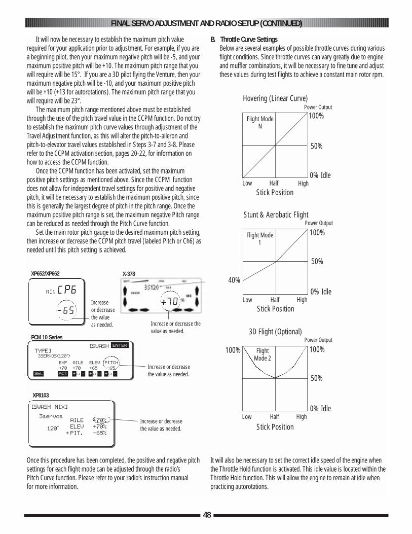
48
It will now be necessary to establish the maximum pitch valuerequired for your application prior to adjustment. For example, if you area beginning pilot, then your maximum negative pitch will be -5, and yourmaximum positive pitch will be +10. The maximum pitch range that youwill require will be 15°. If you are a 3D pilot flying the Venture, then yourmaximum negative pitch will be -10, and your maximum positive pitchwill be +10 (+13 for autorotations). The maximum pitch range that youwill require will be 23°.
The maximum pitch range mentioned above must be establishedthrough the use of the pitch travel value in the CCPM function. Do not tryto establish the maximum pitch curve values through adjustment of theTravel Adjustment function, as this will alter the pitch-to-aileron andpitch-to-elevator travel values established in Steps 3-7 and 3-8. Pleaserefer to the CCPM activation section, pages 20-22, for information onhow to access the CCPM function.
Once the CCPM function has been activated, set the maximumpositive pitch settings as mentioned above. Since the CCPM functiondoes not allow for independent travel settings for positive and negativepitch, it will be necessary to establish the maximum positive pitch, sincethis is generally the largest degree of pitch in the pitch range. Once themaximum positive pitch range is set, the maximum negative Pitch rangecan be reduced as needed through the Pitch Curve function.
Set the main rotor pitch gauge to the desired maximum pitch setting,then increase or decrease the CCPM pitch travel (labeled Pitch or Ch6) asneeded until this pitch setting is achieved.
Once this procedure has been completed, the positive and negative pitchsettings for each flight mode can be adjusted through the radio’s Pitch Curve function. Please refer to your radio’s instruction manual for more information.
B. Throttle Curve SettingsBelow are several examples of possible throttle curves during variousflight conditions. Since throttle curves can vary greatly due to engineand muffler combinations, it will be necessary to fine tune and adjustthese values during test flights to achieve a constant main rotor rpm.
It will also be necessary to set the correct idle speed of the engine whenthe Throttle Hold function is activated. This idle value is located within theThrottle Hold function. This will allow the engine to remain at idle whenpracticing autorotations.
[SWASHTYPE]3SERVOS(120•)
EXP AILE ELEV PITCH
+70 +70 +65 -65
ENTER
SEL ACT + –CL + –CL + –CL
Increase or decreasethe valueas needed. Increase or decrease the
value as needed.
Increase or decreasethe value as needed.
Increase or decreasethe value as needed.
[SWASH MIX]
3servos
120•
XP8103
PCM 10 Series
XP652/XP662 X-378
AILE +70%
ELEV +70%
∞ PIT. -65%
mixCP6
—65
100%
50%
40%
0% Idle
Power OutputHovering (Linear Curve)
Stick PositionLow Half High
Flight ModeN
100%
50%
0% Idle
Power OutputStunt & Aerobatic Flight
Stick PositionLow Half High
Flight Mode1
100% 100%
50%
0% Idle
3D Flight (Optional)
Stick PositionLow Half High
FlightMode 2
Power Output
+70
FINAL SERVO ADJUSTMENT AND RADIO SETUP (CONTINUED)
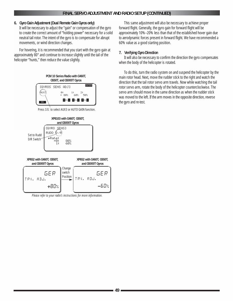
49
6. Gyro Gain Adjustment (Dual Remote Gain Gyros only)It will be necessary to adjust the “gain” or compensation of the gyroto create the correct amount of “holding power” necessary for a solidneutral tail rotor. The intent of the gyro is to compensate for abruptmovements, or wind direction changes.
For hovering, it is recommended that you start with the gyro gain atapproximately 80° and continue to increase slightly until the tail of thehelicopter “hunts,” then reduce the value slightly.
This same adjustment will also be necessary to achieve properforward flight. Generally, the gyro gain for forward flight will beapproximately 10%–20% less than that of the established hover gain dueto aerodynamic forces present in forward flight. We have recommended a60% value as a good starting position.
7. Verifying Gyro DirectionIt will also be necessary to confirm the direction the gyro compensates
when the body of the helicopter is rotated.
To do this, turn the radio system on and suspend the helicopter by themain rotor head. Next, move the rudder stick to the right and watch thedirection that the tail rotor servo arm travels. Now while watching the tailrotor servo arm, rotate the body of the helicopter counterclockwise. Theservo arm should move in the same direction as when the rudder stickwas moved to the left. If the arm moves in the opposite direction, reversethe gyro and re-test.
[GYROS SENS ADJ]
AUX3 0: 1: 2:
∞ 80% 60% 50%
ENTER
SEL+ –CL + –CL + –CL
Press SEL to select AUX3 or AUTO GAIN function.
PCM 10 Series Radio with G460T, G550T, and G5000T Gyros
[GYRO SENS]
RUDD D/R
£Rate: ∞0: 80%1: 60%
XP8103 with G460T, G550T, and G5000T Gyros
Set to RuddD/R Switch
Please refer to your radio’s instructions for more information.
gertrv. adj.
+80%
XP652 with G460T, G550T, and G5000T Gyros
gertrv. adj.
-60%
XP652 with G460T, G550T, and G5000T Gyros
Changeswitch Position
FINAL SERVO ADJUSTMENT AND RADIO SETUP (CONTINUED)
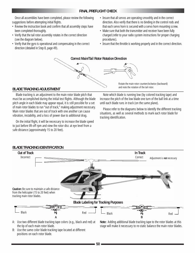
Once all assemblies have been completed, please review the followingsuggestions before attempting initial flights.• Review the instruction book and confirm that all assembly steps have
been completed thoroughly.• Verify that the tail rotor assembly rotates in the correct direction
(see the diagram below).• Verify that the gyro is operational and compensating in the correct
direction (detailed in Step 8, page 49).
• Insure that all servos are operating smoothly and in the correctdirection. Also verify that there is no binding in the control rods andthat each servo horn is secured with a servo horn mounting screw.
• Make sure that both the transmitter and receiver have been fully charged (refer to your radio system instructions for proper charging procedures).
• Insure that the throttle is working properly and in the correct direction.
FINAL PREFLIGHT CHECK
Correct Main/Tail Rotor Rotation Direction
BLADE TRACKING IDENTIFICATION
A: Use two different blade tracking tape colors (e.g., black and red) at the tip of each main rotor blade.
B: Use the same color blade tracking tape located at differentpositions on each rotor blade.
Note: Adding additional blade tracking tape to the rotor blades at thisstage will make it necessary to re-static balance the main rotor blades.
BLADE TRACKING ADJUSTMENTBlade tracking is an adjustment to the main rotor blade pitch that
must be accomplished during the initial test flights. Although the bladepitch angle in each blade may appear equal, it is still possible for a setof main rotor blades to run “out of track,” making adjustment necessary.Main rotor blades that are out of track with one another can causevibration, instability, and a loss of power due to additional drag.
On the initial flight, it will be necessary to increase the blade speedto just before lift-off rpm and view the rotor disc at eye level from asafe distance (approximately 15 to 20 feet).
Note which blade is running low (by colored tracking tape) andincrease the pitch of the low blade one turn of the ball link at a timeuntil each blade runs in track (on the same plane).
Please refer to the diagrams below to identify the different trackingsituations, as well as several methods to mark each rotor blade fortracking identification.
IncorrectOut of Track
CorrectIn Track
Adjustment is not necessary
ARedBlack
BRedBlack
Rotate the main rotor counterclockwise (backward)and note the rotation of the tail rotor.
50
Caution: Be sure to maintain a safe distancefrom the helicopter (15 to 20 feet) whentracking main rotor blades.
Blade Labeling for Tracking Purposes

51
Flight TrainingFlight Simulators
A model helicopter simulator is highly recommended and is an excellent training aid. Simulators like the CSM V10 will help you learn the orientation andinputs needed to fly a model helicopter, without the risk of damaging your model to learn these same reactions. In general, most beginning pilots find that usingan RC simulator prior to their first actual flights with their model increase the speed in which they learn, and also decrease the number of crashes associatedwith learning to fly. Even the most experienced Heli pilots continue to practice with a flight simulator to learn new maneuvers and stick inputs prior to tryingthese maneuvers with their actual models.
Training GearBefore you commence, it is also highly recommended that you first purchase and install helicopter flight training gear to your Venture to prevent accidental
prior to tracking the blades, or attempting to fly the model.
Experienced HelpIt is also highly recommended if possible that you seek help from an experienced RC helicopter pilot prior to your first flights. Contact your local hobby shop
for more information on clubs and pilots in your area.
Where to FlyIt is recommended that for your first flights, you locate a large smooth parking lot or paved surface that is in a private setting. The training gear will allow the
model to slide smoothly on a flat hard surface, which will reduce the risk of tipovers while learning. A smooth grass surface will also work if it is not possible tolocate a large parking lot, however the training gear will have a tendency to catch in the grass which increases the possibility of a tip over.
When to FlyFor your first flights, it is recommended that you chose a day with calm or no wind as the model will be much easier to control without the additional wind
factor. Generally, you will want to pick a day where the wind is below 5 mph if possible for the best results. Please also note that the model should always be positioned nose into the wind for the best results.
Basic Hover Training PracticesOnce you have properly tracked the main rotor blades and have tuned the engine as needed, it is now time to move on to the initial flight training practices
listed below.
Ground SkatingThe first step towards learning to fly is ground skating. The model should be positioned nose into the wind, and the pilots should be located approx-imately
15-20 feet behind the model, and slightly to the left or right. The tail of the model should always face towards the pilot during these initial flight practices. To startground skating, simply increase the throttle slowly until the model starts to become light in the training skids. Next, move the cyclic stick forward slightly; themodel should slide forward. Begin to skate the model slowly to the left, right, forward and backwards gently until you become familiar with the stick inputs. Once you have become comfortable with this, you can also practice rotating the model to the left and right using the rudder stick. Be careful when doing this; ifthe model rotates the nose towards you, the cyclic controls will be reversed.
Short Stationary HoveringOnce you have become comfortable with grounds skating, your next step is to try to perform a short stationary hover. To do this, increase the throttle slowly
until the model starts to lift from the ground. When the model is 1 foot from the ground, gently reduce the throttle so that the model will settle back down gently.Continue this procedure, and try to increase the time that the model remains airborne.It is important that you keep the model within 3 feet of the ground whileperforming this exercise, as this will prevent an accidental tip over.
Long Stationary HoveringOnce you have become comfortable with the short stationary hover, the next step is to try to increase the length of time that you are able to keep the model in
stationary hover. Continue to practice this exercise until you are able to keep the model in a stationary hover for a full tank of fuel.
Traveling HoverOnce you have become comfortable with the long stationary hover, the next step is to try to perform a traveling hover. To do this, lift the model into a
stationary hover approximately 1 foot from the ground. Next, move the cyclic stick forward gently, the model will start moving forward. Once the model hastraveled 10–15 feet, gently pull back on the cyclic stick until the model returns to stationary hover. Next, gently move the cyclic stick backwards until the modelreturns to its original position in stationary hover. Repeat this exercise for left and right cyclic as well.
Once you have completed these exercises, you are well on your way to learning to Hover. Please seek advise from an experienced heli pilot in your area onflight progression from this stage forward.
ADVICE AND BASIC HOVER TRAINING PRACTICES

52
EngineAfter each day of flying, fully drain the fuel tank. Then, start the engine and let it idle until the engine and the fuel line are completely burned
off. It is also suggested that an after-run oil be used to prevent premature engine corrosion.
Tail Rotor BeltPeriodically check the tension on the tail drive belt (as shown in Step 1-2, page 8) to insure that it has sufficient tension for proper
engagement. It is especially important to check this after initial test flights.
Check All Nuts and BoltsA helicopter is subject to high vibration during flight. It is important to check that all screws, nuts, and bolts are properly secured after each
day of flying. It is also suggested that you perform a “quick” inspection between each initial test flight for approximately the first 6–10 flights.
Check Ball Link WearCheck to insure that all universal links fit freely but securely to the control balls. If there is excessive play noted, replace the universal link
in question.
Battery MaintenanceCheck to insure that your batteries are properly mounted and charged. The most frequent cause of crashes (aside from pilot error) is battery
failure or disconnection. Be certain that your batteries are fully charged and limit your flight time to 3 or 4 flights between charging. If more flighttime is required, purchase a reliable quick field charger.
CleaningAt the end of each flight or flying session, wipe down your helicopter with a clean towel or rag. This is also a good time to inspect all parts for
tightness or fatigue. A clean, well-maintained helicopter will provide you with many hours of trouble-free flight.
GENERAL MAINTENANCE

53
VENTURE 50 3D TROUBLESHOOTING GUIDE
PROBLEM CAUSE CURE
Helicopter vibrates excessively a. Rotor blades out of balance Re-balance rotor bladesb. Flybar/paddles not centered Re-center flybar on rotor headc. Engine running roughly Re-adjust engine lean/rich settingsd. Excessive clutch run out Re-align clutch assembly
Engine runs inconsistent a. Incorrect fuel mixture Re-adjust engine settingsb. Fuel line problem Check/replace lines (including
inside the tank)c. Glow plug damaged Replace glow plug
Main rotor blades do not track a. Blade pitch not equal Re-set blade pitch w/ gauge and retestb. Blades warped or twisted Check and replace as needed
Model "wobbles" in hover a. Rotor rpm too low Increase throttle at hover or decrease pitch
Clutch grabs when at idle a. Engine rpm too high Reduce trim value/engine rpmb. Engine/clutch mis-aligned Re-align and retest
Model will not lift off the ground a. Engine too rich Lean needle valve settingsb. Blade pitch incorrect Re-check with pitch gaugec. Throttle curve incorrect Re-check throttle curve settings
Model rotates uncontrollably a. Gyro direction reversed Re-check gyro direction and retryb. Tail servo reversed Re-check servo direction and retryc. Gyro gain too low Increase gyro gain and retryd. Main rotor rpm too low Increase throttle or decrease pitch
Model constantly drifts in same direction a. Linkage out of adjustment Re-check linkages per manualb. Servo centering not correct Re-check servo neutral and resetc. Trim levers not centered Check TX trim lever position
For additional questions, please contact:Venture Help Line: 217-355-9511
9a.m.–5p.m. Mon–Fri CSTE-mail: [email protected]
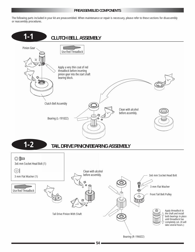
54
1-1 CLUTCH BELL ASSEMBLY
PREASSEMBLED COMPONENTS
The following parts included in your kit are preassembled. When maintenance or repair is necessary, please refer to these sections for disassembly or reassembly procedures.
Pinion Gear
Clutch Bell Assembly
Bearing (L-1910ZZ)
Clean with alcoholbefore assembly.
Apply a very thin coat of redthreadlock before insertingpinion gear into the start shaftbearing block.
Use Red Threadlock
Use Red Threadlock
1-2 TAIL DRIVE PINION/BEARING ASSEMBLY
3x6 mm Socket Head Bolt (1)
3 mm Flat Washer (1)
Tail Drive Pinion With Shaft
3x6 mm Socket Head Bolt
3 mm Flat Washer
Front Tail Belt Pulley
Bearing (R-1960ZZ)
Apply threadlock tothe shaft and installboth bearings in placeuntil threadlock hascompletely set. (It willtake several hours.)
Clean with alcoholbefore assembly.
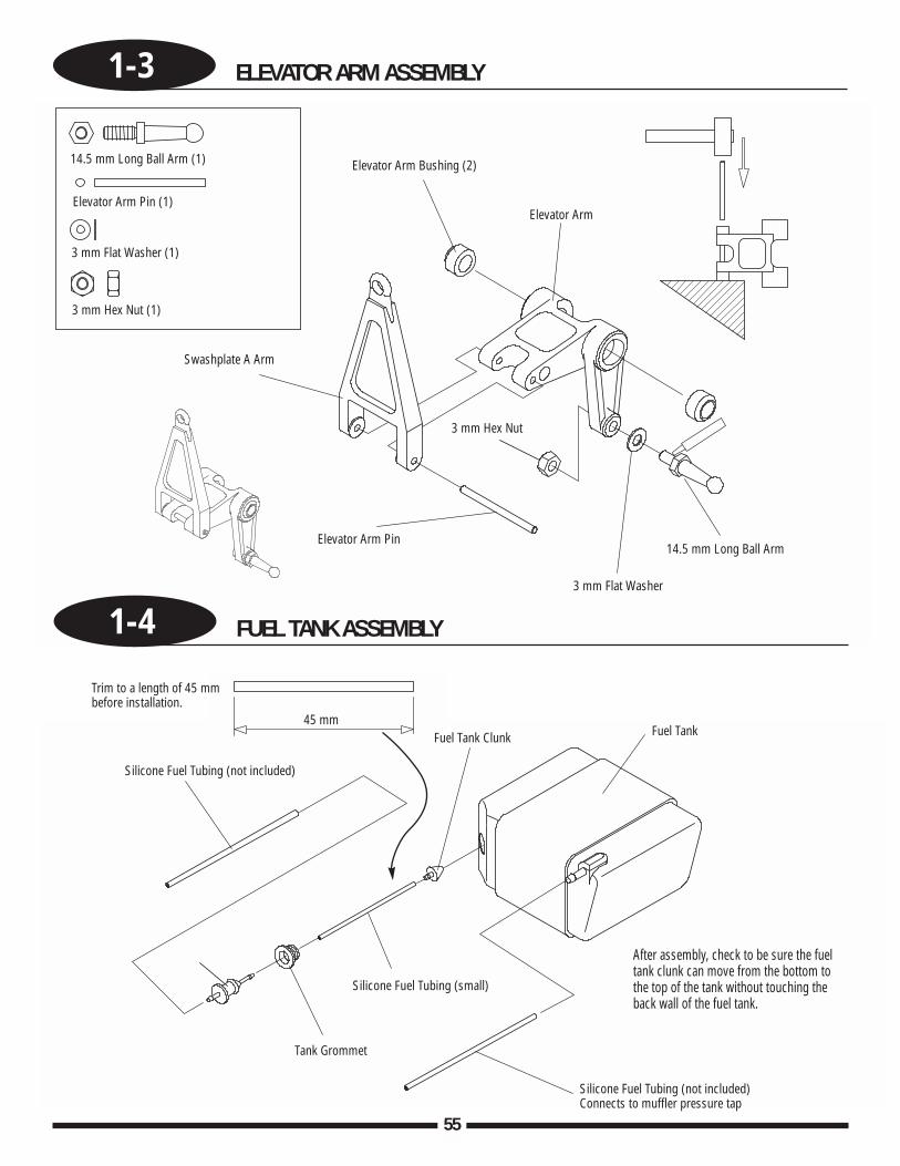
1-3 ELEVATOR ARM ASSEMBLY
55
Elevator Arm Bushing (2)
Elevator ArmElevator Arm Pin (1)
Elevator Arm Pin
Swashplate A Arm
3 mm Flat Washer (1)
3 mm Flat Washer
3 mm Hex Nut (1)
3 mm Hex Nut
14.5 mm Long Ball Arm (1)
14.5 mm Long Ball Arm
1-4 FUEL TANK ASSEMBLY
45 mm
Silicone Fuel Tubing (not included)
Trim to a length of 45 mmbefore installation.
Silicone Fuel Tubing (small)
Tank Grommet
Silicone Fuel Tubing (not included)Connects to muffler pressure tap
Fuel Tank Clunk Fuel Tank
After assembly, check to be sure the fueltank clunk can move from the bottom tothe top of the tank without touching theback wall of the fuel tank.
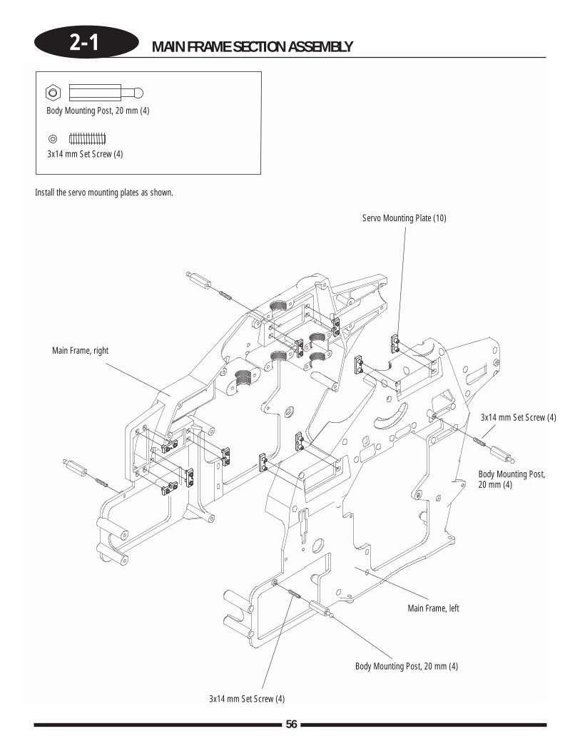
56
2-1 MAIN FRAME SECTION ASSEMBLY
Body Mounting Post, 20 mm (4)
3x14 mm Set Screw (4)
Servo Mounting Plate (10)
Main Frame, right
Install the servo mounting plates as shown.
Main Frame, left
3x14 mm Set Screw (4)
3x14 mm Set Screw (4)
Body Mounting Post, 20 mm (4)
Body Mounting Post, 20 mm (4)
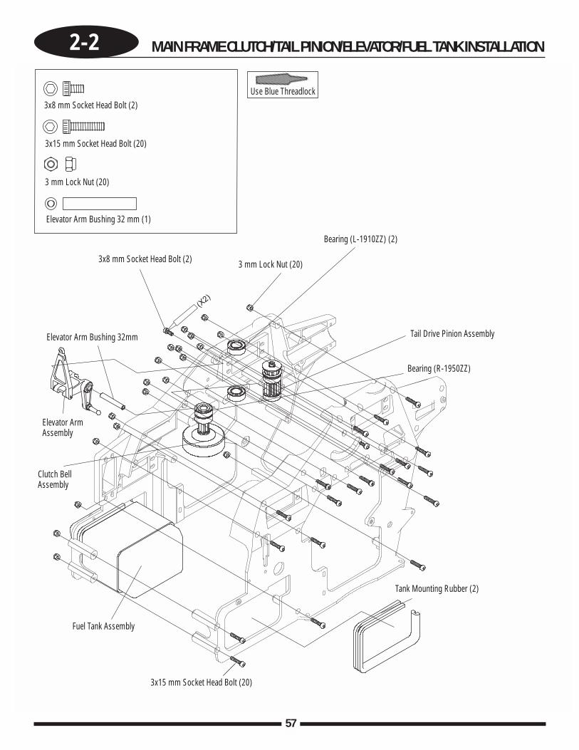
2-2 MAIN FRAME CLUTCH/TAIL PINION/ELEVATOR/FUEL TANK INSTALLATION
57
(X2)
3x8 mm Socket Head Bolt (2)
3x8 mm Socket Head Bolt (2)
3x15 mm Socket Head Bolt (20)
3x15 mm Socket Head Bolt (20)
Fuel Tank Assembly
Clutch BellAssembly
3 mm Lock Nut (20)
3 mm Lock Nut (20)
Bearing (L-1910ZZ) (2)
Bearing (R-1950ZZ)
Tank Mounting Rubber (2)
Tail Drive Pinion Assembly
Elevator Arm Bushing 32 mm (1)
Elevator Arm Bushing 32mm
Elevator ArmAssembly
Use Blue Threadlock
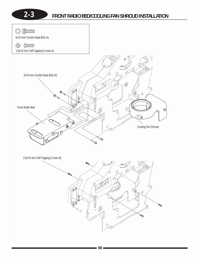
58
2-3 FRONT RADIO BED/COOLING FAN SHROUD INSTALLATION
3x10 mm Socket Head Bolt (4)
2.6x10 mm Self-Tapping Screw (4)
2.6x10 mm Self-Tapping Screw (4)
Cooling Fan Shroud
3x10 mm Socket Head Bolt (4)
Front Radio Bed
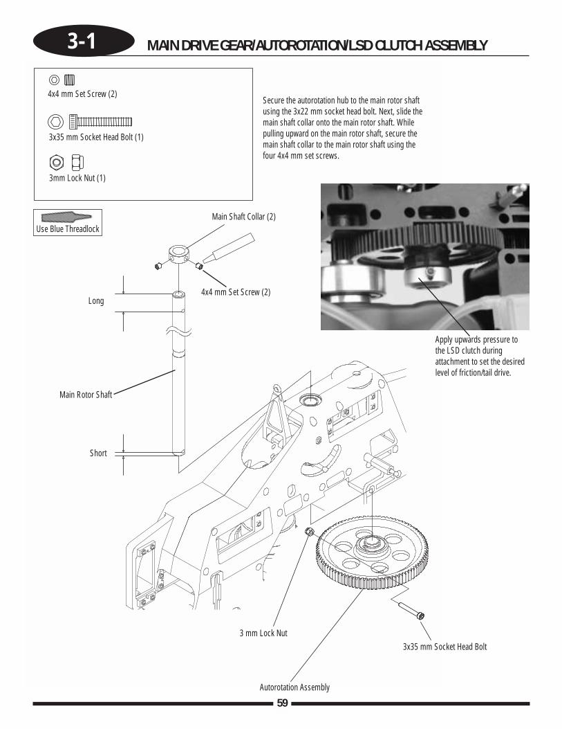
3-1 MAIN DRIVE GEAR/AUTOROTATION/LSD CLUTCH ASSEMBLY
59
4x4 mm Set Screw (2)
4x4 mm Set Screw (2)
Main Shaft Collar (2)
3x35 mm Socket Head Bolt (1)
3mm Lock Nut (1)
3 mm Lock Nut
Autorotation Assembly
3x35 mm Socket Head Bolt
Long
Short
Main Rotor Shaft
Use Blue Threadlock
Secure the autorotation hub to the main rotor shaftusing the 3x22 mm socket head bolt. Next, slide themain shaft collar onto the main rotor shaft. Whilepulling upward on the main rotor shaft, secure themain shaft collar to the main rotor shaft using thefour 4x4 mm set screws.
Apply upwards pressure tothe LSD clutch duringattachment to set the desiredlevel of friction/tail drive.
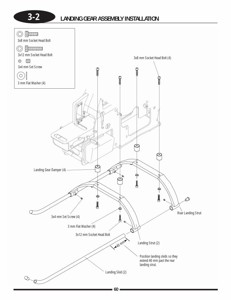
60
3-2 LANDING GEAR ASSEMBLY INSTALLATION
3x8 mm Socket Head Bolt
3x8 mm Socket Head Bolt (4)3x12 mm Socket Head Bolt
3x4 mm Set Screw
3x4 mm Set Screw (4)
3 mm Flat Washer (4)
3x12 mm Socket Head Bolt
3 mm Flat Washer (4)
Landing Gear Damper (4)
Landing Skid (2)
40 mm Landing Strut (2)
Position landing skids so theyextend 40 mm past the rearlanding strut.
Rear Landing Strut
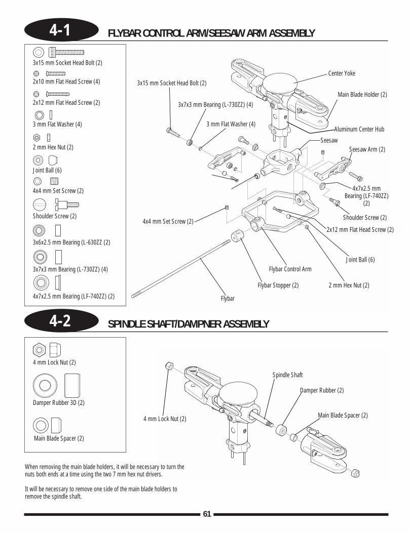
4-1 FLYBAR CONTROL ARM/SEESAW ARM ASSEMBLY
4-2 SPINDLE SHAFT/DAMPNER ASSEMBLY
61
Center Yoke3x15 mm Socket Head Bolt (2)
3 mm Flat Washer (4)
3x15 mm Socket Head Bolt (2)
2x10 mm Flat Head Screw (4)
2x12 mm Flat Head Screw (2)
3 mm Flat Washer (4)
2 mm Hex Nut (2)
Joint Ball (6)
4x4 mm Set Screw (2)
4 mm Lock Nut (2)
4 mm Lock Nut (2)
Spindle Shaft
Damper Rubber (2)
Main Blade Spacer (2)
Damper Rubber 3D (2)
Main Blade Spacer (2)
When removing the main blade holders, it will be necessary to turn thenuts both ends at a time using the two 7 mm hex nut drivers.
It will be necessary to remove one side of the main blade holders toremove the spindle shaft.
Shoulder Screw (2)
3x6x2.5 mm Bearing (L-630ZZ (2)
3x7x3 mm Bearing (L-730ZZ) (4)
4x7x2.5 mm Bearing (LF-740ZZ) (2)
3x7x3 mm Bearing (L-730ZZ) (4)Main Blade Holder (2)
SeesawSeesaw Arm (2)
4x7x2.5 mmBearing (LF-740ZZ)
(2)
Shoulder Screw (2)
2x12 mm Flat Head Screw (2)
Joint Ball (6)
2 mm Hex Nut (2)
Flybar Control Arm
Flybar Stopper (2)
Flybar
4x4 mm Set Screw (2)
Aluminum Center Hub
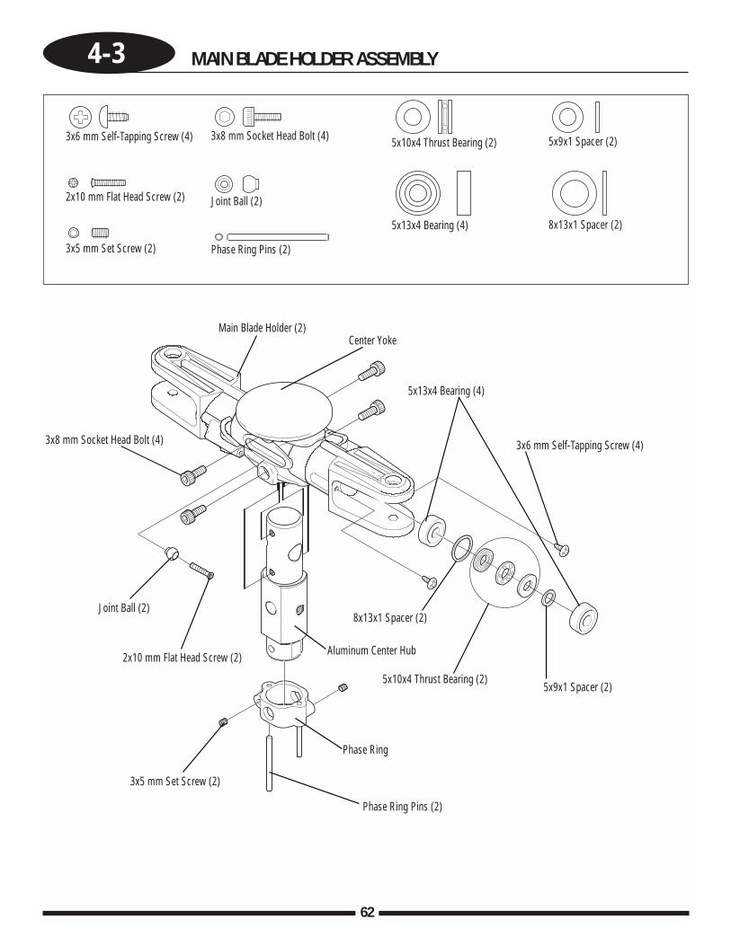
62
4-3 MAIN BLADE HOLDER ASSEMBLY
3x6 mm Self-Tapping Screw (4)
2x10 mm Flat Head Screw (2)
3x5 mm Set Screw (2)
Joint Ball (2)
3x8 mm Socket Head Bolt (4)
Phase Ring Pins (2)
5x10x4 Thrust Bearing (2)
5x13x4 Bearing (4)
5x9x1 Spacer (2)
8x13x1 Spacer (2)
Phase Ring Pins (2)
3x8 mm Socket Head Bolt (4)
Joint Ball (2)
2x10 mm Flat Head Screw (2)
5x13x4 Bearing (4)
Main Blade Holder (2)
3x5 mm Set Screw (2)
8x13x1 Spacer (2)
5x10x4 Thrust Bearing (2)5x9x1 Spacer (2)
3x6 mm Self-Tapping Screw (4)
Phase Ring
Aluminum Center Hub
Center Yoke
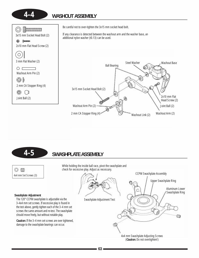
4-4 WASHOUT ASSEMBLY
4-5 SWASHPLATE ASSEMBLY
63
Swashplate AdjustmentThe 120° CCPM swashplate is adjustable via the 3–4x4 mm set screws. If excessive play is found in the test above, gently tighten each of the 3–4 mm setscrews the same amount and re-test. The swashplateshould move freely, but without notable play.
Caution: If the 3–4 mm set screws are over tightened, damage to the swashplate bearings can occur.
While holding the inside ball race, pivot the swashplate andcheck for excessive play. Adjust as necessary.
Swashplate Adjustment Test
CCPM Swashplate Assembly
Upper Swashplate Ring
Aluminum LowerSwashplate Ring
4x4 mm Swashplate Adjusting Screws(Caution: Do not overtighten!)
4x4 mm Set Screws (3)
Ball Bearing
3x15 mm Socket Head Bolt (2)
Washout Arm Pin (2)
2 mm CA Stopper Ring (4) Washout Link (2) Washout Arm (2)
Washout Base Steel Washer
Joint Ball (2)
2x10 mm FlatHead Screw (2)
3x15 mm Socket Head Bolt (2)
2x10 mm Flat Head Screw (2)
3 mm Flat Washer (2)
Washout Arm Pin (2)
2 mm CA Stopper Ring (4)
Joint Ball (2)
Be careful not to over-tighten the 3x15 mm socket head bolt.
If any clearance is detected between the washout arm and the washer base, anadditional nylon washer (t0.13) can be used.
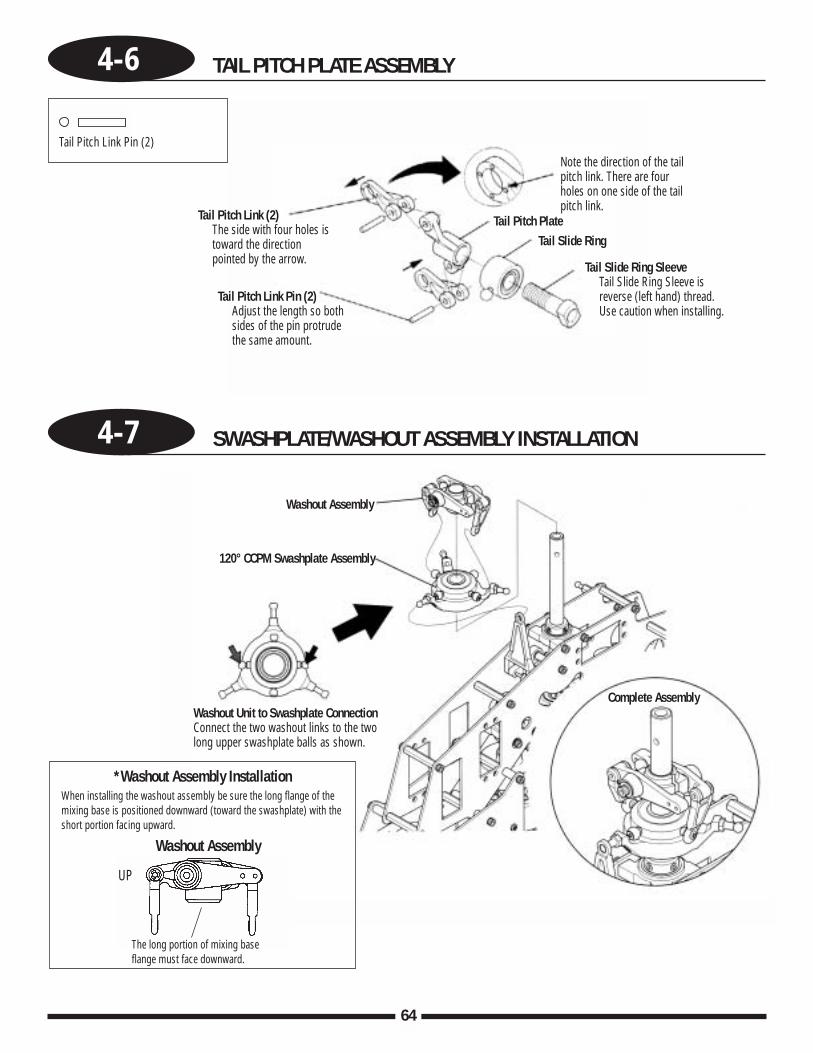
64
4-6 TAIL PITCH PLATE ASSEMBLY
4-7 SWASHPLATE/WASHOUT ASSEMBLY INSTALLATION
Complete Assembly
Washout Assembly
120° CCPM Swashplate Assembly
Washout Unit to Swashplate ConnectionConnect the two washout links to the twolong upper swashplate balls as shown.
*Washout Assembly InstallationWhen installing the washout assembly be sure the long flange of themixing base is positioned downward (toward the swashplate) with theshort portion facing upward.
The long portion of mixing baseflange must face downward.
UP
Washout Assembly
Tail Pitch Link Pin (2)
Tail Pitch Link (2)The side with four holes istoward the directionpointed by the arrow.
Tail Pitch Link Pin (2)Adjust the length so bothsides of the pin protrudethe same amount.
Note the direction of the tailpitch link. There are fourholes on one side of the tailpitch link.
Tail Pitch PlateTail Slide Ring
Tail Slide Ring SleeveTail Slide Ring Sleeve isreverse (left hand) thread.Use caution when installing.
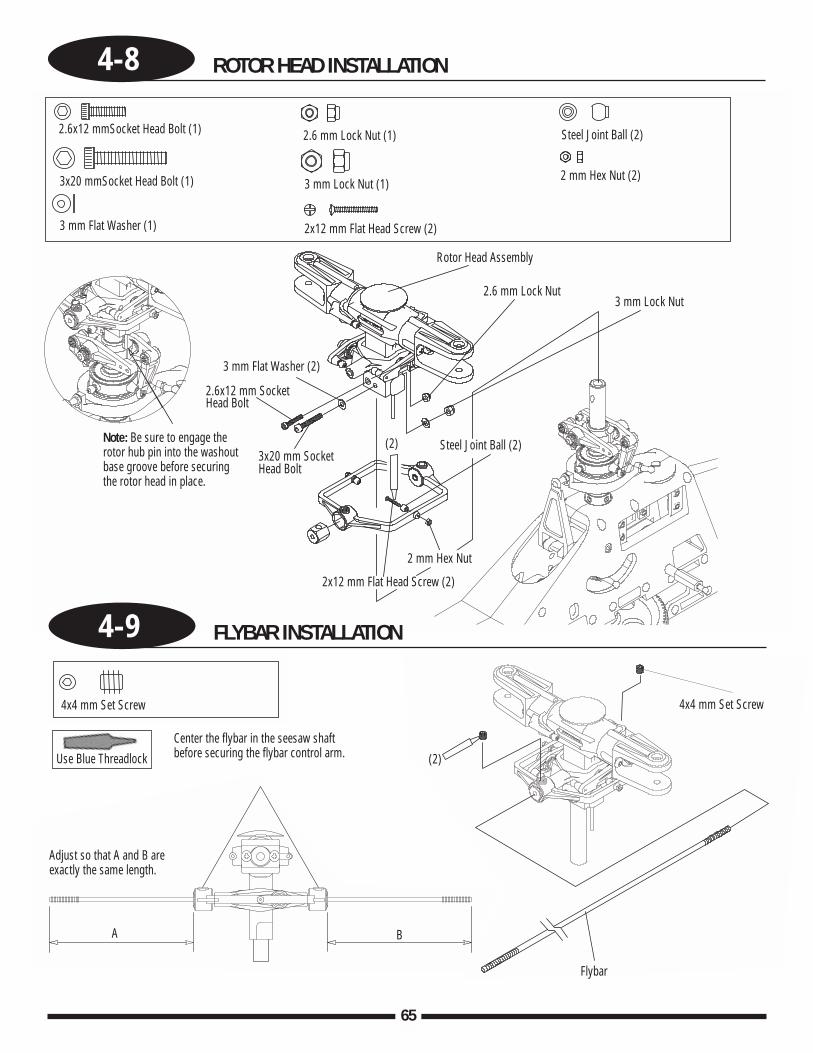
4-8 ROTOR HEAD INSTALLATION
65
2.6x12 mmSocket Head Bolt (1)
3x20 mmSocket Head Bolt (1)
3 mm Flat Washer (1) 2x12 mm Flat Head Screw (2)
2x12 mm Flat Head Screw (2)
Steel Joint Ball (2)
Steel Joint Ball (2)
Rotor Head Assembly
2 mm Hex Nut (2)
2 mm Hex Nut
2.6 mm Lock Nut (1)
2.6 mm Lock Nut3 mm Lock Nut
3 mm Lock Nut (1)
3x20 mm SocketHead Bolt
Note: Be sure to engage therotor hub pin into the washoutbase groove before securingthe rotor head in place.
2.6x12 mm SocketHead Bolt
3 mm Flat Washer (2)
4x4 mm Set Screw
Flybar
Center the flybar in the seesaw shaftbefore securing the flybar control arm.
4-9 FLYBAR INSTALLATION
4x4 mm Set Screw
Use Blue Threadlock
Adjust so that A and B areexactly the same length.
A B
(2)
(2)
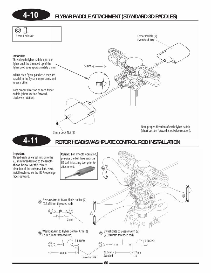
66
4-10 FLYBAR PADDLE ATTACHMENT (STANDARD 3D PADDLES)
Flybar Paddle (2)(Standard 3D)
3 mm Lock Nut (2)
5 mm
Note proper direction of each flybar paddle(short section forward, clockwise rotation).
Important:Thread each flybar paddle onto theflybar until the threaded tip of theflybar protrudes approximately 5 mm.
Adjust each flybar paddle so they areparallel to the flybar control arms andto each other.
Note proper direction of each flybarpaddle (short section forward,clockwise rotation).
4-11 ROTOR HEAD/SWASHPLATE CONTROL ROD INSTALLATION
Important:Thread each universal link onto the2.3 mm threaded rod to the lengthshown below. Not the correctdirection of the universal link. Next,install each rod so the JR Propo logofaces outward.
Option: For smooth operation,pre-size the ball links with theJR ball link sizing tool prior toattachment.
Seesaw Arm to Main Blade Holder (2)(2.3x15mm threaded rod)
3 mm
Washout Arm to Flybar Control Arm (2)(2.3x20mm threaded rod)
Swashplate to Seesaw Arm (2)(2.3x40mm threaded rod)
JR PROPO
Universal Link48mm 23.5mm
Standard17mm3D
JR PROPO
3 mm Lock Nut
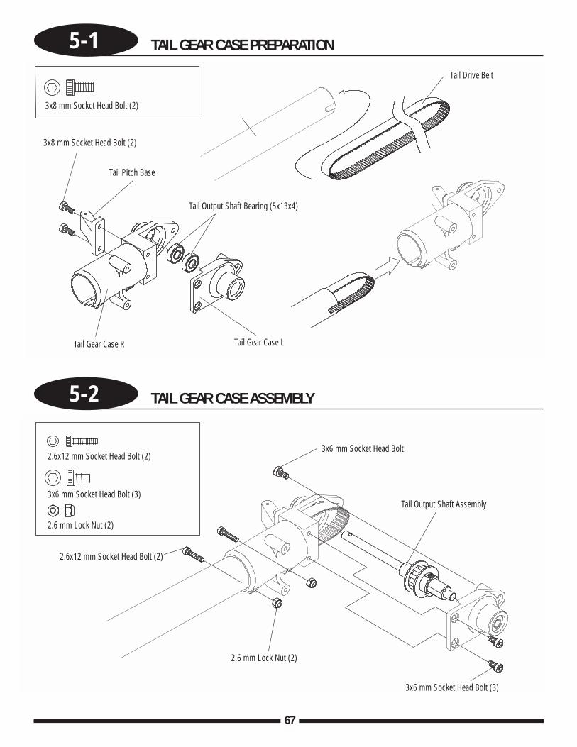
67
5-1 TAIL GEAR CASE PREPARATION
5-2 TAIL GEAR CASE ASSEMBLY
3x8 mm Socket Head Bolt (2)
3x8 mm Socket Head Bolt (2)
Tail Pitch Base
Tail Gear Case R Tail Gear Case L
Tail Drive Belt
Tail Output Shaft Bearing (5x13x4)
2.6x12 mm Socket Head Bolt (2)
2.6x12 mm Socket Head Bolt (2)
3x6 mm Socket Head Bolt (3)
3x6 mm Socket Head Bolt
3x6 mm Socket Head Bolt (3)
Tail Output Shaft Assembly
2.6 mm Lock Nut (2)
2.6 mm Lock Nut (2)
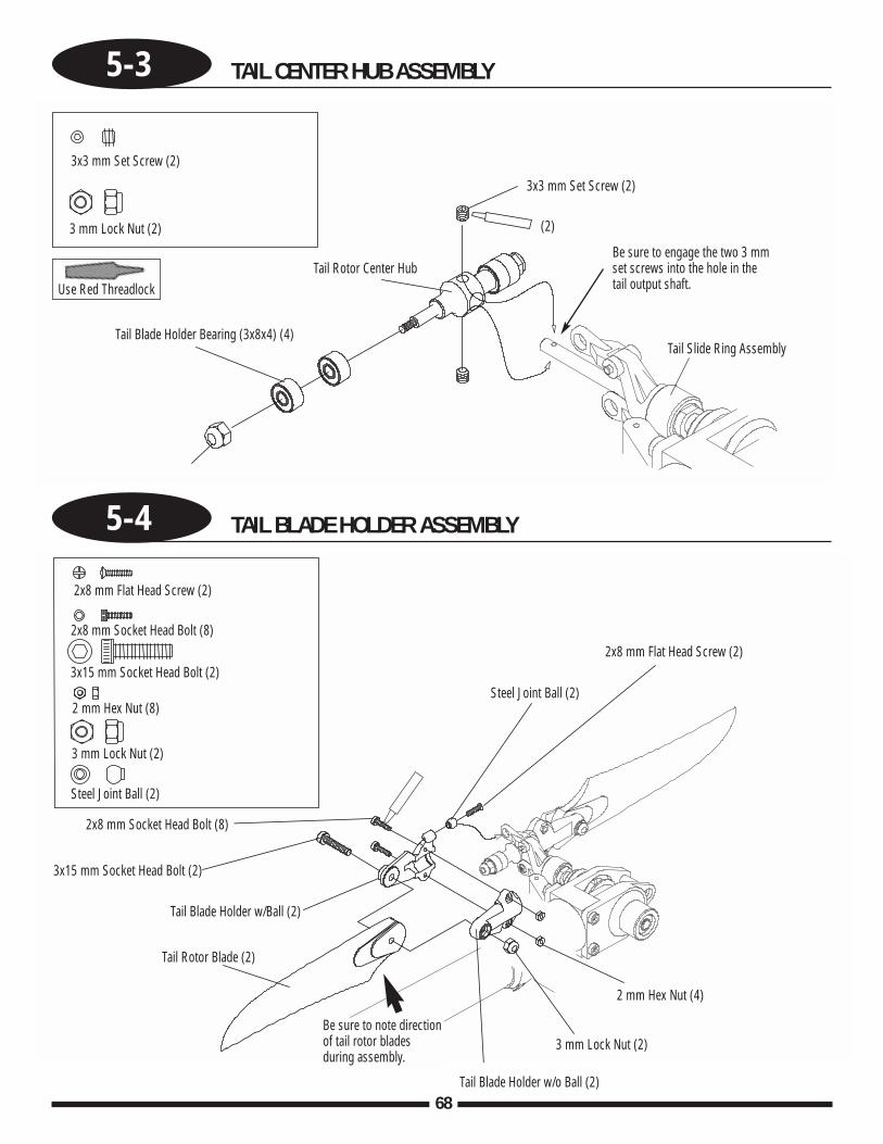
68
5-3 TAIL CENTER HUB ASSEMBLY
5-4 TAIL BLADE HOLDER ASSEMBLY
3x3 mm Set Screw (2)
3x3 mm Set Screw (2)
(2)3 mm Lock Nut (2)
Tail Rotor Center Hub
Tail Slide Ring Assembly
Be sure to engage the two 3 mmset screws into the hole in thetail output shaft.
Tail Blade Holder Bearing (3x8x4) (4)
Use Red Threadlock
2x8 mm Flat Head Screw (2)
2x8 mm Flat Head Screw (2)2x8 mm Socket Head Bolt (8)
3x15 mm Socket Head Bolt (2)
3x15 mm Socket Head Bolt (2)
Tail Blade Holder w/Ball (2)
Be sure to note directionof tail rotor bladesduring assembly.
Tail Blade Holder w/o Ball (2)
Tail Rotor Blade (2)
2 mm Hex Nut (8)
2 mm Hex Nut (4)
3 mm Lock Nut (2)
3 mm Lock Nut (2)
Steel Joint Ball (2)
Steel Joint Ball (2)
2x8 mm Socket Head Bolt (8)
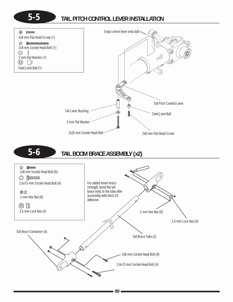
5-5 TAIL PITCH CONTROL LEVER INSTALLATION
5-6 TAIL BOOM BRACE ASSEMBLY (x2)
69
2x8 mm Flat Head Screw (1)
2x8 mm Flat Head Screw
2x8 mm Socket Head Bolt (1)
2x20 mm Socket Head Bolt
2 mm Flat Washer (1)
2 mm Flat Washer
Steel Joint Ball (1)
Steel Joint Ball
Tail Pitch Control Lever
Snap control lever onto ball.
Tail Lever Bushing
2x8 mm Socket Head Bolt (8)
2x8 mm Socket Head Bolt (8)
2.6x15 mm Socket Head Bolt (4)
2.6x15 mm Socket Head Bolt (4)
2 mm Hex Nut (8)
2 mm Hex Nut (8)
2.6 mm Lock Nut (4)
Tail Brace Tube (2)
2.6 mm Lock Nut (4)
Tail Brace Connector (4)
For added boom bracestrength, bond the tailbrace ends to the tube afterassesmbly with thick CAadhesive.
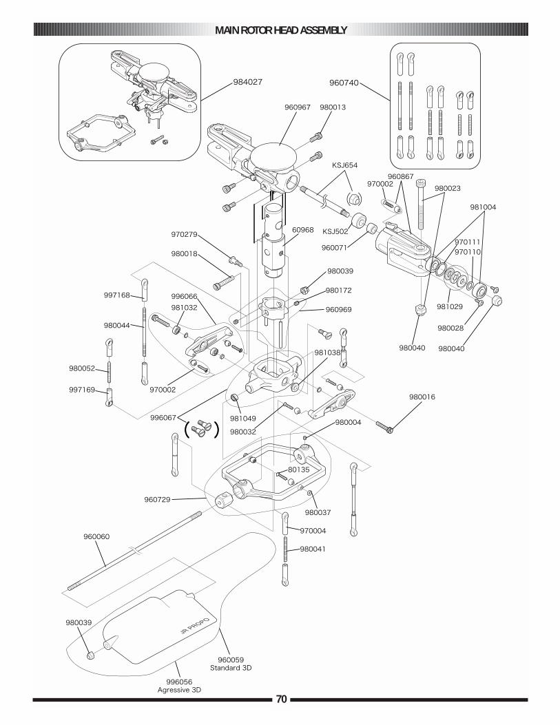
MAIN ROTOR HEAD ASSEMBLY
70

71
MAIN ROTOR HEAD ASSEMBLY PARTS
PART # DESCRIPTION COMMENTS/ADDITIONAL CONTENTS QUANTITY
JRP960729 Flybar Control Arm Flybar Control Arm 1Steel Joint Balls 2Flat Head Screw 2x12 mm 22 mm Hex Nuts 24x4 mm Set Screws 2
JRP960060 Flybar 540 mm Flybar 540 mm (Training) 2JRP996057 Flybar 410 mm Flybar 410 mm (3D) 2JRP980009 2.6x12 mm Socket Head Bolt 2.6x12 mm Socket Head Bolt 10JRP980060 3x20 mm Socket Head Bolt 3x20 mm Socket Head Bolt 10JRP980135 Flat Head Screw 2x12 mm Flat Head Screw 2x12 mm 10JRP960059 Flybar Paddle Standard Flybar Paddle 2
3mm Lock Nut 2JRP996067 Seesaw Arm Seesaw Arm 2
Seesaw Bearing Inner 2Steel Joint Ball 4Flat Head Screw M2x10 4
JRP996056 3D Flybar Paddle 3D Flybar Paddle 2JRP997168 Universal Ball Links, Black Universal Ball Links, Black 10JRP997169 Universal Ball Links Short, Black Universal Ball Links Short, Black 5JRP980052 Control Rod M2.3x15 Control Rod M2.3x15 2JRP980041 Control Rod M2.3x20 Control Rod M2.3x20 2JRP980044 Control Rod M2.3x40 Control Rod M2.3x40 2JRP980023 Main Blade Bolt Main Blade Bolt 4x30 mm 2JRP984027 Main Rotor Head Assembly Main Rotor Head Assembly 1JRP960968 Aluminum Main Rotor Hub Main Rotor Hub 1JRP960969 Phase Ring w/Pins Phase Ring with Pins 1JRP960967 Plastic Yoke Plastic Yoke with screws 1JRP970279 Seesaw Shaft Bolt Seesaw Shaft Bolt 2KSJ654 Heavy Duty Spindle Shaft Spindle Shaft 1KSJ502 Damper Rubber 3D Damper Rubber 2JRP960071 Damper Collar Damper Collar 2JRP981029 Thrust Bearing Set Thrust Bearings 2JRP980028 Self-Tapping Screw 3x6 mm Self Tapping Screw 3x6 mm 10JRP980040 4 mm Lock Nut 4mm Lock Nut 10JRP960867 Main Blade Holder Main Blade Holder 2
Steel Joint Ball 2Flat Head Screw 2x10 mm 2
JRP996067 Seesaw Shaft Seesaw Shaft 1Seesaw Shaft Bolt 2
JRP960740 Head Linkage Set Control Rod M2.3x40 2Control Rod M2.3x20 2Control Rod M2.3x15 2Ball Links, Long 8Ball Links, Short 4
JRP970002 Joint Balls/2x10 mm Screws Joint Balls/2x10 mm Screws 10JRP981004 Ball Bearings, 5x13x4 mm Ball Bearings, 5x13x4 mm 2JRP980039 Lock Nuts, 3 mm Lock Nuts, 3 mm 10JRP980129 Lock Nuts, 2.6 mm Lock Nuts, 2.6 mm 10JRP981032 Washout Arm Bearings Washout Arm Bearings 2JRP981038 Seesaw Pivot Bearings Seesaw Pivot Bearings 2JRP981049 Seesaw/Flybar Bearings Seesaw/Flybar Bearings 2JRP980032 Flat Head Screws, 2x10 mm Flat Head Screws, 2x10 mm 10JRP980037 Hex Nuts, 2 mm Hex Nuts, 2 mm 10JRP980069 Set Screws, 4x6 mm Set Screws, 4x6 mm 10JRP980004 Set Screws, 4x4 mm Set Screws, 4x4 mm 10
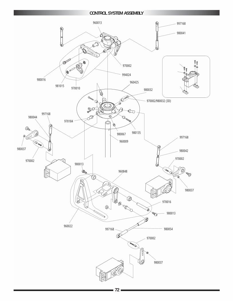
CONTROL SYSTEM ASSEMBLY
72
960013 997168
980041
970002
994024
960425
980032
980135980067
960009
970184
970010981015
980016
997168980044
980037
970002980013
960848
997168
980042
970002
980037
970016
980013
980054
970002
980037
997168960022
970002/980032 (3D)
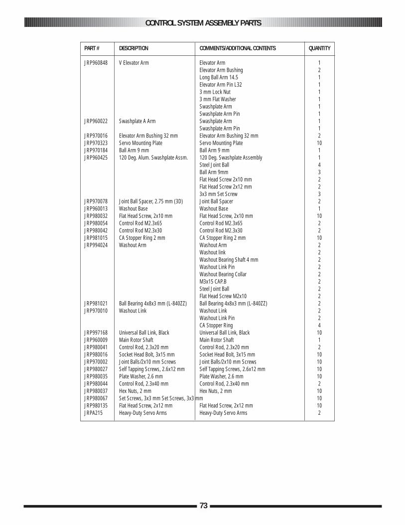
CONTROL SYSTEM ASSEMBLY PARTS
73
PART # DESCRIPTION COMMENTS/ADDITIONAL CONTENTS QUANTITY
JRP960848 V Elevator Arm Elevator Arm 1Elevator Arm Bushing 2Long Ball Arm 14.5 1Elevator Arm Pin L32 13 mm Lock Nut 13 mm Flat Washer 1Swashplate Arm 1Swashplate Arm Pin 1
JRP960022 Swashplate A Arm Swashplate Arm 1Swashplate Arm Pin 1
JRP970016 Elevator Arm Bushing 32 mm Elevator Arm Bushing 32 mm 2JRP970323 Servo Mounting Plate Servo Mounting Plate 10JRP970184 Ball Arm 9 mm Ball Arm 9 mm 1JRP960425 120 Deg. Alum. Swashplate Assm. 120 Deg. Swashplate Assembly 1
Steel Joint Ball 4Ball Arm 9mm 3Flat Head Screw 2x10 mm 2Flat Head Screw 2x12 mm 23x3 mm Set Screw 3
JRP970078 Joint Ball Spacer, 2.75 mm (3D) Joint Ball Spacer 2JRP960013 Washout Base Washout Base 1JRP980032 Flat Head Screw, 2x10 mm Flat Head Screw, 2x10 mm 10JRP980054 Control Rod M2.3x65 Control Rod M2.3x65 2JRP980042 Control Rod M2.3x30 Control Rod M2.3x30 2JRP981015 CA Stopper Ring 2 mm CA Stopper Ring 2 mm 10JRP994024 Washout Arm Washout Arm 2
Washout link 2Washout Bearing Shaft 4 mm 2Washout Link Pin 2Washout Bearing Collar 2M3x15 CAP.B 2Steel Joint Ball 2Flat Head Screw M2x10 2
JRP981021 Ball Bearing 4x8x3 mm (L-840ZZ) Ball Bearing 4x8x3 mm (L-840ZZ) 2JRP970010 Washout Link Washout Link 2
Washout Link Pin 2CA Stopper Ring 4
JRP997168 Universal Ball Link, Black Universal Ball Link, Black 10JRP960009 Main Rotor Shaft Main Rotor Shaft 1JRP980041 Control Rod, 2.3x20 mm Control Rod, 2.3x20 mm 2JRP980016 Socket Head Bolt, 3x15 mm Socket Head Bolt, 3x15 mm 10JRP970002 Joint Balls/2x10 mm Screws Joint Balls/2x10 mm Screws 10JRP980027 Self Tapping Screws, 2.6x12 mm Self Tapping Screws, 2.6x12 mm 10JRP980035 Plate Washer, 2.6 mm Plate Washer, 2.6 mm 10JRP980044 Control Rod, 2.3x40 mm Control Rod, 2.3x40 mm 2JRP980037 Hex Nuts, 2 mm Hex Nuts, 2 mm 10JRP980067 Set Screws, 3x3 mm Set Screws, 3x3 mm 10JRP980135 Flat Head Screw, 2x12 mm Flat Head Screw, 2x12 mm 10JRPA215 Heavy-Duty Servo Arms Heavy-Duty Servo Arms 2
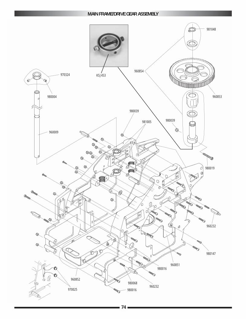
MAIN FRAME/DRIVE GEAR ASSEMBLY
74
981048
960853
980039
980019
981005
980039
960009
980004
970324
960852
970025 980016
980068960232
980016960851
980147
960232
960854KSJ453

MAIN FRAME/DRIVE GEAR ASSEMBLY PARTS
75
PART # DESCRIPTION COMMENTS/ADDITIONAL CONTENTS QUANTITY
JRP960850 Main Frame L/R Main Frame R 1Main Frame L 1
JRP980068 3x15 mm Set Screw 3x15 mm Set Screw 10JRP960232 Body Mounting Standoff L21 Body Mounting Standoff L21 2JRP980013 3x8 mm Socket Head Bolt 3x8 mm Socket Head Bolt 10JRP980039 3 mm Lock Nut 3mm Lock Nut 10JRP960851 Cooling Fan Shroud Cooling Fan Shroud 1
2.6x10 mm Self-Tapping Screw 42.6 mm Flat Washers 4
JRP980147 M2.6x10 Self-Tapping Screw 2.6x10 mm Self-Tapping Screw 10JRP960852 Front Radio Bed Front Radio Bed 1
3x10 mm Socket Head Bolts 4JRP970324 Main Shaft Collar Main Shaft Collar 1
4x4 mm Set Screw 2JRP980004 4x4 mm Set Screw 4x4 mm Set Screw 10JRP980019 3x22 mm Socket Head Bolt 3x22 mm Socket Head Bolt 10JRP960853 Main Drive Gear 88T Main Drive Gear 88T 1JRP960854 Autorotation Bearing Assembly One-way Bearing 1KSJ453 LSD Clutch LSD clutch with o-ring 1
Autorotation Shaft 1Autorotation Spacer 2CA Stopper Ring 11 mm 1
JRP981048 CA Stopper Ring 11 mm CA Stopper Ring 11 mm 1JRP960009 Main Rotor Shaft Main Rotor Shaft 1JRP981005 Main Rotor Shaft Bearings Main Rotor Shaft Bearings 2JRP980016 Socket Head Bolts, 3x15 mm Socket Head Bolts, 3x15 mm 10JRP970025 Switch Damper Rubber Switch Damper Rubber 4
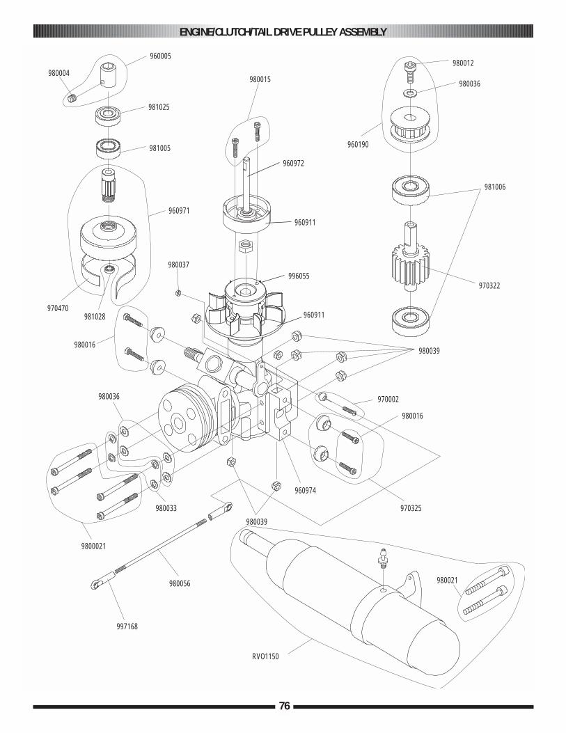
ENGINE/CLUTCH/TAIL DRIVE PULLEY ASSEMBLY
76
960005
981025
981005
960971
980037
980016
981028970470
980004980015
960972
960911
996055
960911
960190
980012
981006
970322
980039
970002
980016
970325
980021
960974
980039
980033
9800021
980036
980056
997168
RVO1150
980036

ENGINE/CLUTCH/TAIL DRIVE PULLEY ASSEMBLY PARTS
77
PART # DESCRIPTION COMMENTS/ADDITIONAL CONTENTS QUANTITY
JRP981005 Ball Bearing 10x19x7 mm Ball Bearing 10x19x7 mm 2JRP960971 Clutch Bell Assembly Clutch Bell Assembly 1JRP970470 Clutch Lining Clutch Lining 1JRP970322 Tail Drive Pinion Tail Drive Pinion 1
3x6 mm Socket Head Bolt 13 mm Flat Washer 1
JRP960190 Front Tail Belt Pulley Front Tail Belt Pulley 13x6 mm Socket Head Bolt 13 mm Flat Washer 1
JRP981006 Ball Bearing 6x19x6 mm Ball Bearing 6x19x6 mm 2JRP981025 Ball Bearing 5x19x6 mm Ball Bearing 5x19x6 mm 2JRP980016 3x15 mm Socket Head Bolt 3x15 mm Socket Head Bolt 10JRP980021 3x30 mm Socket Head Bolt 3x30 mm Socket Head Bolt 10JRP980033 3mm Spring Washer 3mm Spring Washer 10JRP960974 Engine Mount .50 (Aluminum) Engine Mount .50 1JRP996054 Cooling Fan Blades Fan Blades & Screws 1JRP996055 Cooling Fan Hub Cooling Fan Hub 1JRP960972 Clutch Assembly w/ Bearing Clutch Assembly w/Bearing 1
3x12 mm Socket Head Bolt 2JRP970325 Engine Mount/Frame Washers Engine Mount/Frame Washers 4
3x12 mm Socket Head Bolt 43mm Lock Nut 4
JRP960005 Starter Hex Adaptor Starter Hex Adaptor 14x4 mm Set Screw 1
JRP960471 Starter Shaft Starter Shaft 1JRP981007 Ball Bearing 20x32x7 mm Ball Bearing 20x32x7 mm 1JRP980056 Control Rod M2.3x85 Control Rod M2.3x85 2JRP980004 Set Screws, 4x4 mm Set Screws, 4x4 mm 10JRP981028 Clutch Bell Bearing Clutch Bell Bearing 1JRP980015 Socket Head Bolts, 3x12 mm Socket Head Bolts, 3x12 mm 10JRP980036 Plate Washers, 3 mm Plate Washers, 3 mm 10JRP980039 Lock Nuts, 3 mm Lock Nuts, 3 mm 10JRP970002 Joint Balls/2x10 mm Screws Joint Balls/2x10 mm Screws 10JRP997168 Universal Ball Link, Black Universal Ball Link, Black 10RVO1150 Muffler, .46-.50 Muffler, .46-.50 1
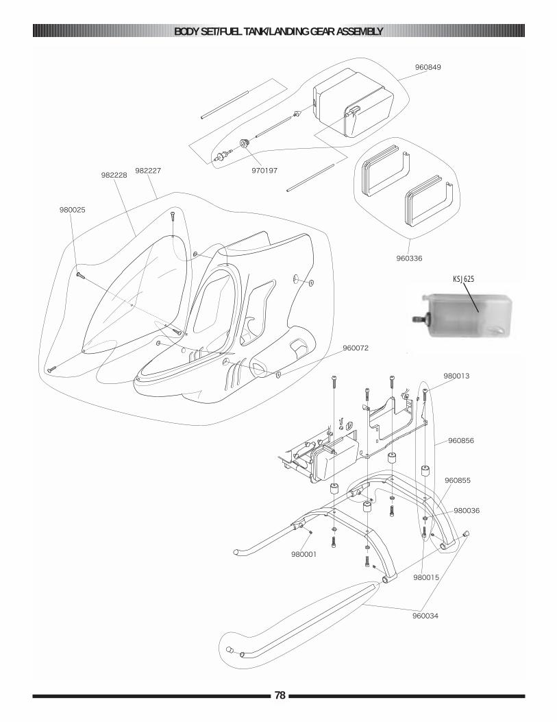
BODY SET/FUEL TANK/LANDING GEAR ASSEMBLY
78
KSJ625
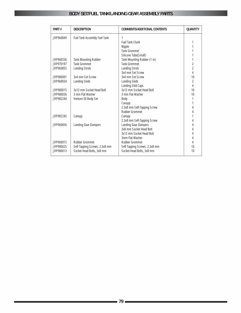
BODY SET/FUEL TANK/LANDING GEAR ASSEMBLY PARTS
79
PART # DESCRIPTION COMMENTS/ADDITIONAL CONTENTS QUANTITY
JRP960849 Fuel Tank Assembly Fuel Tank 1Fuel Tank Clunk 1Nipple 1Tank Grommet 1Silicone Tube(Small) 1
JRP960336 Tank Mounting Rubber Tank Mounting Rubber (1 m) 1JRP970197 Tank Grommet Tank Grommet 2JRP960855 Landing Struts Landing Struts 2
3x4 mm Set Screw 4JRP980001 3x4 mm Set Screw 3x4 mm Set Screw 10JRP960034 Landing Skids Landing Skids 2
Landing Skid Caps 4JRP980015 3x12 mm Socket Head Bolt 3x12 mm Socket Head Bolt 10JRP980036 3 mm Flat Washer 3 mm Flat Washer 10JRP982244 Venture 50 Body Set Body 1
Canopy 12.3x8 mm Self-Tapping Screw 4Rubber Grommet 4
JRP982245 Canopy Canopy 12.3x8 mm Self-Tapping Screw 4
JRP960856 Landing Gear Dampers Landing Gear Dampers 43x8 mm Socket Head Bolt 43x12 mm Socket Head Bolt 43mm Flat Washer 4
JRP960072 Rubber Grommet Rubber Grommet 4JRP980025 Self-Tapping Screws, 2.3x8 mm Self-Tapping Screws, 2.3x8 mm 10JRP980013 Socket Head Bolts, 3x8 mm Socket Head Bolts, 3x8 mm 10
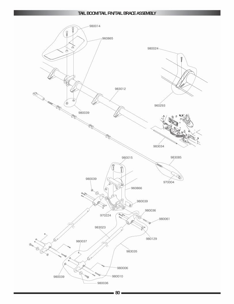
TAIL BOOM/TAIL FIN/TAIL BRACE ASSEMBLY
80

TAIL BOOM/TAIL FIN/TAIL BRACE ASSEMBLY PARTS
81
PART # DESCRIPTION COMMENTS/ADDITIONAL CONTENTS QUANTITY
JRP980129 2.6 mm Lock Nut 2.6 mm Lock Nut 10JRP980014 3x10 mm Socket Head Bolt 3x10 mm Socket Head Bolt 10JRP996064 Horizontal Fin Horizontal Fin 1JRP960865 Fin Set Horizontal and Vertical Fins 1JRP983012 Tail Boom Tail Boom 1JRP983035 Dual Tail Brace Set Tail Brace Tube 430 mm 2
Tail Brace Connector 43x15 mm Socket Head Bolt 42.6x15 mm Socket Head Bolt 42x8 mm Socket Head Bolt 83 mm Lock Nut 42.6 mm Lock Nut 42 mm Hex Nut 8
JRP960866 Tail Brace Clamp Tail Brace Clamp U 1Tail Brace Clamp L 13x12 mm Socket Head Bolt 23x15 mm Socket Head Bolt 13mm Lock Nut 33mm Flat Washer 2
JRP983078 Tail Control Rod 965mm Tail Control Rod 965 mm 1Universal Link 2
JRP960293 Tail Rod Guide B Set Tail Rod Guide B Set 4Rod Guide 1Tail Control Rod Guide B 4Tail Control Rod Bush 13x10 mm Socket Head Bolt 12x8 mm Socket Head Bolt 4
JRP983034 Tail Control Tubing 600 mm Tail Control Tubing 600 mm 2JRP980024 Self-Tapping Screws, 2x8 mm Self-Tapping Screws, 2x8 mm 10JRP980039 Lock Nuts, 3 mm Lock Nuts, 3 mm 10JRP997168 Universal Ball Link, Black Universal Ball Link, Black 10JRP981015 CA Stopper Ring, 2 mm CA Stopper Ring, 2 mm 10JRP980016 CA Stopper Ring, 1.5 mm CA Stopper Ring, 1.5 mm 10JRP980036 Plate Washers, 3 mm Plate Washers, 3 mm 10JRP980006 Socket Head Bolts, 2x8 mm Socket Head Bolts, 2x8 mm 10JRP980010 Socket Head Bolts, 2.6x15 mm Socket Head Bolts, 2.6x15 mm 10JRP980037 Hex Nuts, 2 mm Hex Nuts, 2 mm 10
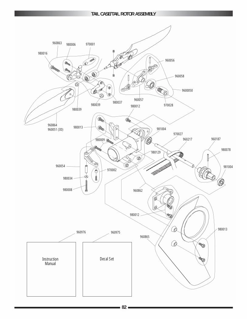
TAIL CASE/TAIL ROTOR ASSEMBLY
82
970001980006960863
980016
980039
960864960051 (3D) 980013
960054
980034
980008
970002
980009
960056
960058
9600050
970028
981004
980129
970027960217 960187
980078
981004
960862
980012
960975960865
980013960976
InstructionManual
Decal Set
980039980037
960057
980012
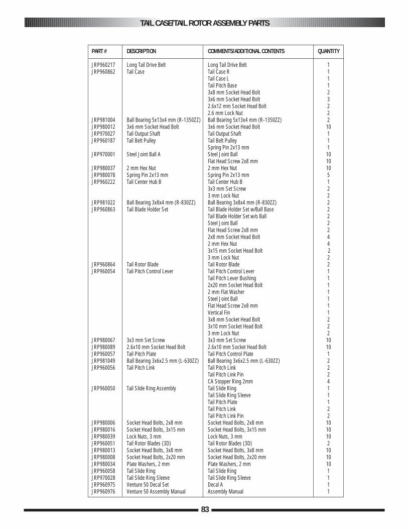
TAIL CASE/TAIL ROTOR ASSEMBLY PARTS
83
PART # DESCRIPTION COMMENTS/ADDITIONAL CONTENTS QUANTITY
JRP960217 Long Tail Drive Belt Long Tail Drive Belt 1JRP960862 Tail Case Tail Case R 1
Tail Case L 1Tail Pitch Base 13x8 mm Socket Head Bolt 23x6 mm Socket Head Bolt 32.6x12 mm Socket Head Bolt 22.6 mm Lock Nut 2
JRP981004 Ball Bearing 5x13x4 mm (R-1350ZZ) Ball Bearing 5x13x4 mm (R-1350ZZ) 2JRP980012 3x6 mm Socket Head Bolt 3x6 mm Socket Head Bolt 10JRP970027 Tail Output Shaft Tail Output Shaft 1JRP960187 Tail Belt Pulley Tail Belt Pulley 1
Spring Pin 2x13 mm 1JRP970001 Steel Joint Ball A Steel Joint Ball 10
Flat Head Screw 2x8 mm 10JRP980037 2 mm Hex Nut 2 mm Hex Nut 10JRP980078 Spring Pin 2x13 mm Spring Pin 2x13 mm 5JRP960222 Tail Center Hub B Tail Center Hub B 1
3x3 mm Set Screw 23 mm Lock Nut 2
JRP981022 Ball Bearing 3x8x4 mm (R-830ZZ) Ball Bearing 3x8x4 mm (R-830ZZ) 2JRP960863 Tail Blade Holder Set Tail Blade Holder Set w/Ball Base 2
Tail Blade Holder Set w/o Ball 2Steel Joint Ball 2Flat Head Screw 2x8 mm 22x8 mm Socket Head Bolt 42 mm Hex Nut 43x15 mm Socket Head Bolt 23 mm Lock Nut 2
JRP960864 Tail Rotor Blade Tail Rotor Blade 2JRP960054 Tail Pitch Control Lever Tail Pitch Control Lever 1
Tail Pitch Lever Bushing 12x20 mm Socket Head Bolt 12 mm Flat Washer 1Steel Joint Ball 1Flat Head Screw 2x8 mm 1Vertical Fin 13x8 mm Socket Head Bolt 23x10 mm Socket Head Bolt 23 mm Lock Nut 2
JRP980067 3x3 mm Set Screw 3x3 mm Set Screw 10JRP980089 2.6x10 mm Socket Head Bolt 2.6x10 mm Socket Head Bolt 10JRP960057 Tail Pitch Plate Tail Pitch Control Plate 1JRP981049 Ball Bearing 3x6x2.5 mm (L-630ZZ) Ball Bearing 3x6x2.5 mm (L-630ZZ) 2JRP960056 Tail Pitch Link Tail Pitch Link 2
Tail Pitch Link Pin 2CA Stopper Ring 2mm 4
JRP960050 Tail Slide Ring Assembly Tail Slide Ring 1Tail Slide Ring Sleeve 1Tail Pitch Plate 1Tail Pitch Link 2Tail Pitch Link Pin 2
JRP980006 Socket Head Bolts, 2x8 mm Socket Head Bolts, 2x8 mm 10JRP980016 Socket Head Bolts, 3x15 mm Socket Head Bolts, 3x15 mm 10JRP980039 Lock Nuts, 3 mm Lock Nuts, 3 mm 10JRP960051 Tail Rotor Blades (3D) Tail Rotor Blades (3D) 2JRP980013 Socket Head Bolts, 3x8 mm Socket Head Bolts, 3x8 mm 10JRP980008 Socket Head Bolts, 2x20 mm Socket Head Bolts, 2x20 mm 10JRP980034 Plate Washers, 2 mm Plate Washers, 2 mm 10JRP960058 Tail Slide Ring Tail Slide Ring 1JRP970028 Tail Slide Ring Sleeve Tail Slide Ring Sleeve 1JRP960975 Venture 50 Decal Set Decal A 1JRP960976 Venture 50 Assembly Manual Assembly Manual 1

©2003 Horizon Hobby, Inc.Distributed exclusively by Horizon Hobby, Inc.
www.horizonhobby.com3886