verification of completeness and consistency in knowledge-based
TRANSCRIPT

Verification of completeness and consistency in
knowledge-based systems
A design theory
Master thesis within IS
Author: Petter Fogelqvist
Tutor: Anneli Edman
Department of Informatics and Media
Uppsala University
Sweden
December 2011

ii
Master Thesis within Information Systems (IS)
Title: Verification of completeness and consistency in knowledge-
based systems: a design theory
Author: Petter Fogelqvist
Tutor: Anneli Edman
Date: 2011 December
Keywords: Verification, completeness, consistency, software quality, design theory,
knowledge-base, rule-based systems, inexact-reasoning, certainty factors
Abstract
Verification of knowledge-bases is a critical step to ensure the quality of a knowledge-based
system. The success of these systems depends heavily on how qualitative the knowledge is.
Manual verification is however cumbersome and error prone, especially for large knowledge-
bases.
This thesis provides a design theory, based upon the suggested framework by Gregor and
Jones (2007). The theory proposes a general design of automated verification tools, which
have the abilities of verifying heuristic knowledge in rule-based systems utilizing certainty
factors. Included is a verification of completeness and consistency technique customized to
this class of knowledge-based systems.
The design theory is instantiated in a real-world verification tool development project at
Uppsala University. Considerable attention is given to the design and implementation of this
artifact – uncovering issues and considerations involved in the development process.
For the knowledge management practitioner, this thesis offers guidance and recommendations
for automated verification tool development projects. For the IS research community, the
thesis contributes with extensions of existing design theory, and reveals some of the
complexity involved with verification of a specific rule-based system utilizing certainty
factors.

iii
Acknowledgments
This was a hard one, requiring a lot of hard work, considerations and coffee breaks. There
have been a lot of obstacles to overcome along the way, such as broken ribs, writers block and
other commitments. Altogether I feel the process has been worthwhile, and I have learned a
lot along the way.
I would like to start and give credits to my supervisor, Anneli Edman, who has been a great
support during the whole process. Thank you for all the time you have invested, for your great
feedback and suggestions of improvement. To the whole staff at the department at
Information and Media, thank you for the inclusive and welcoming atmosphere I have
perceived during my studies and work at the department. I especially want to mention
Researcher Jonas Sjöström, Professor Per Ågerfalk and Lecturer Torsten Palm for giving me
good advices and support. To my fellow classmates, it has been a joy to get to know all of you
and I wish you the best of luck in the future.
To my co-bandmembers – our weekly jamsessions helped me release thesis-related
frustrations. I also want to promote the podcasts by Ricky Gervais, Stephen Merchant and
Karl Pilkington which has repeatedly been the background-soundtrack during the whole
thesis. Thanks to Uppsala University, SHE AB, Jakob Fogelqvist & Ransta Trädgård for
giving me various part-time employments during the thesis writing, and by that, financial
support. Finally, I want to thank my family; father Bo-Göran, mother Britta, and my three
brothers Johan, Simon and Jonathan for your healthy levels of support and interest in my
work.

iv
Table of Contents
1 Introduction ....................................................................................................................... 1
1.1 Problem ........................................................................................................................ 2
1.2 Motivation .................................................................................................................... 2
1.3 Aim ............................................................................................................................... 3
1.4 Research Questions ...................................................................................................... 3
1.5 Limitations and Demarcations ..................................................................................... 3
1.6 Definition of Key Terminology .................................................................................... 3
1.7 Disposition ................................................................................................................... 4
1.8 Audience ....................................................................................................................... 5
Research Method ............................................................................................................... 6
2.1 Design Science in Information Systems (IS) ............................................................... 6
2.2 Eliciting the System Requirements .............................................................................. 9
2.3 Methodology for Instantiating the Design Theory ..................................................... 10
2.4 Evaluation of the Results ............................................................................................ 10
3 Theoretical Background ................................................................................................. 12
3.1 Knowledge-Based Systems (KBS) ............................................................................. 12
3.1.1 Experts and Expertise .......................................................................................... 13
3.1.2 Components of a Knowledge-Based System ...................................................... 14
3.1.3 Benefits of Knowledge-Based Systems ............................................................. 15
3.2 Knowledge Engineering ............................................................................................. 16
3.2.1 Knowledge Acquisition ....................................................................................... 17
3.2.2 Knowledge Representation ................................................................................. 18
3.2.3 Knowledge Verification and Validation ............................................................. 19
3.2.4 Inferencing .......................................................................................................... 19
3.2.5 Explanation and Justification .............................................................................. 20
3.3 Knowledge Represented by Rules .............................................................................. 20
3.3.1 Rule-Based Systems ............................................................................................ 20
3.3.2 Business Rules and Rule Engines ....................................................................... 22
3.4 Inexact Reasoning in Knowledge-Based Systems ..................................................... 22
3.4.1 Statistical Probabilities ........................................................................................ 23
3.4.2 Certainty Factors ................................................................................................. 23
3.4.3 Fuzzy Logic ......................................................................................................... 29
3.5 Verification of a Knowledge-Base ............................................................................. 30

v
3.6 Prolog ......................................................................................................................... 36
3.6.1 Syntax of Prolog .................................................................................................. 36
3.6.2 Meta-Programming ............................................................................................. 38
3.7 Klöver ......................................................................................................................... 39
3.7.1 Architecture of Klöver ........................................................................................ 40
3.7.2 Representations in the Knowledge Database ...................................................... 41
3.7.3 Inference Mechanism .......................................................................................... 42
Development of the Design Theory ................................................................................ 43
4.1 System Requirements ................................................................................................. 43
4.2 Design ......................................................................................................................... 44
4.2.1 The Rule-Base in Klöver ..................................................................................... 44
4.2.2 Inconsistencies in the Rule-Base of Klöver ........................................................ 45
4.3 Instantiation of the Design Theory ............................................................................. 51
4.3.1 Overview of development life-cycle ................................................................... 52
4.3.2 Implementation of a Redundancy Checker ......................................................... 53
4.3.3 Implementation of a Subsumption Checker ........................................................ 58
4.3.4 Implementation of a Completeness Checker ....................................................... 61
4.4 Prototype of the Artifact ............................................................................................. 64
4.5 Evaluation of the Artifact ........................................................................................... 67
5 Conclusions ...................................................................................................................... 69
6 Discussion ......................................................................................................................... 73
6.1 Future Work ............................................................................................................... 73
References ........................................................................................................................... 75
Appendices .......................................................................................................................... 80
Appendix 1: Manual of Klöver ........................................................................................ 80
Appendix 2: Prolog Tutorial ............................................................................................ 92

vi
List of Figures
Figure 2.1: Guidelines for design science research Hevner et al (2004) .................................... 6
Figure 2.2: Components of a design theory Gregor& Jones (2007) .......................................... 7
Figure 3.1: Components of a knowledge-based system ........................................................... 14
Figure 3.2: Narrow definition of the process of knowledge engineering (Turban, 2011) ....... 16
Figure 3.3: Broad definition pf the process of knowledge engineering (Durkin, 1994) .......... 17
Figure 3.4: The production system model (Durkin, 1994) ....................................................... 21
Figure 3.5: Syntactic inconsistencies in a rule-base ................................................................. 32
Figure 3.6: Illustration of collaboration between different components in Klöver .................. 41
Figure 4.1: Integration of the artifact into Klöver .................................................................... 52
Figure 4.2: Screenshot of output of detected redundant rules .................................................. 57
Figure 4.3: Screenshot of output of detected subsumed rules .................................................. 60
Figure 4.4: Screenshot of output of detected inconsistencies affecting the completeness ....... 64
Figure 4.5: Screenshot of the main menu of klöver in SICStus ............................................... 65
Figure 4.6: Screenshot of the verification menu of Klöver in SICStus .................................... 65
Figure 4.7: Screenshot of the help menu .................................................................................. 66
Figure 4.8: Screenshot of the output information regarding redundancy................................. 66
Figure 4.9: Screenshot of the examples regarding redundancy in a rule-base ......................... 67
Figure 4.10: Implemented verification of consistency and completeness .............................. 68

vii
List of Tables
Table 3.1: Relationships between P and MB, MD and CF (Durkin, 1994) ............................. 25
Table 3.2: CF value interpretation (Durkin, 1994) ................................................................... 25
Table 3.3: Formula for estimating CF of conclusions .............................................................. 26
Table 3.4: Formulas for estimating CF of multiple premises (Durkin, 1994).......................... 26
Table 3.5: Formulas for combining two certainty factors for the same conclusion ................. 27
Table 3.6: Fuzzy set of the fuzzy term ‖tall‖ ........................................................................... 29
Table 3.7: Fuzzy set of the fuzzy term ‖very tall‖ ................................................................... 30
Table 5.1: Summary of errors affecting the completeness and consistency in rule-bases ....... 70
1
"Knowledge is hassle”
Karl Pilkington
1 Introduction
Developing computer programs simulating human reasoning have for a long time been a topic
of interest for Artificial Intelligence (AI) researchers (Metaxiotis et al, 2003). A result from
these efforts is the Knowledge-Based Systems (KBS), which are one branch of applied AI.
The basic idea behind KBS is to transfer knowledge from a human to a computer. The system
simulates a human consultant, giving advices to a user, and can explain the logic behind the
advice (Turban & Aronson, 2001).
The application of KBS has been proved to obtain solutions to problems that often cannot be
dealt with by other, more traditional and orthodox methods (Liao, 2005). During the 2000s,
KBS have been applied in a variety of problem domains, such as decision making (Mockler et
al, 2000), environmental protection (Gomolka et al, 2000), urban design (Xirogiannis et al,
2004), and planar robots (Sen et al, 2004).
In general, the major bottleneck in the development of KBS is the knowledge acquisition
stage, which is the process of capturing and transforming knowledge from sources to a
computer program (Metaxiotis, 2003; Turban, 2011). Poor knowledge acquisition may result
in knowledge that is incomplete and inconsistent (Turban, 2011). This is problematic because
the success of a KBS depends heavily on how qualitative the knowledge is (Metaxiotis,
2003).
The startup of this thesis was an inquiry about developing a rule-base debugger of a
knowledge-based system called Klöver. The inquiry came from the department of Informatics
and Media at Uppsala University, Sweden. In consultation with the client, who also was to
become my supervisor, the project was decided to be the foundation for this Master thesis
within IS.

2
1.1 Problem
The quality of software remains a key business differentiator. A survey by International Data
Corporation (IDC) found that the costs of debugging are still significant for business and IT
organizations. It proposed the necessity of improved automated approaches for code analysis
and testing to help enable more secure, successful, better managed software implementations
(Coverity press release, 2008).
Software development has evolved from an art to an engineering science. This science is
called software engineering and was early defined as (Adrion et al, 1982):
“The practical application of scientific knowledge in the design and construction of
computer programs and the associated documentation required to develop, operate, and
maintain them.”
From this definition follows that the progress of software development is dependent on the
development of relevant and sound scientific knowledge. However, as first proposed by
Orlikowsi and Iacono (2001), the research community in the field of IS has not deeply
engaged its core subject matter – the information technology (IT) artifact. Design-oriented
research may be described as fundamental to the IS discipline (March and Storey, 2008), and
perhaps also for the business and IT industry.
Validation and verification are essential steps in all system development, to ensure the quality
of the software (Gonzalez et al, 1993; Sommerville, 2007). Traditional verification, validation
and testing of knowledge-based systems are conducted by the knowledge engineer. These
processes include reading the knowledge-base looking for syntactic and semantic errors, and
searching for mismatch between the output of the system and the expertise. This tends to be
time consuming, error prone and does not guarantee finding all anomalies in the knowledge-
base, especially for large systems (Bahill, 1991). This is the motive for developing tools
helping the knowledge engineer debug the knowledge-base.
1.2 Motivation
Verification of completeness and consistency in knowledge-based systems is a topic early
recognized and elaborated upon by researchers such as Buchanan & Shortcliffe (1982) and
Suwa et al (1982). Further contributions enriching the subject were later work by, for
example, Cragunt & Steudel (1986), Nguyen et al (1987), Preece (1990), and O´Keefe &
O´Leary (1993). Examples of automated verification tools developed for knowledge-based
systems are ONCOCIN (Shortcliffe et al, 1981), CHECK (Nguyen et al (1987), and EVA
(Stachowitz et al, 1987). A common trait of previous research is a focus on verification of
categorical knowledge in knowledge-based systems, and the attempt of generalizing theory
about verification of completeness and consistency. However, there is a lack of theory

3
regarding how verification tools really should be designed and implemented, visualizing the
principles inherent in the design of such an artifact.
1.3 Aim
The purpose is to propose an applicable design theory regarding development of debugging
tools for verification of diffuse knowledge in knowledge-bases. These tools should have the
ability to detect the complete set of anomalies that may exist in a knowledge-base, affecting
the consistency and completeness. Furthermore, the instantiations of the design theory should
result in artifacts interacting with the user in a comprehensible way. Not only for the necessity
of presenting the results of the debugging in an understandable way, but also for increasing
the possibility of using the debugger as a learning tool for knowledge representation.
An additional goal is to provide insight into the process of developing this kind of artifacts,
possibly useful for both the research community and the industry.
1.4 Research Questions
In the realms of knowledge-based systems and software quality, this thesis focuses on the
following research questions:
How can a verification tool with the ability of debugging knowledge-bases be developed?
What properties are essential in verification tools debugging knowledge-bases that utilize
certainty factors?
1.5 Limitations and Demarcations
The topic explored in this thesis is delimited to verification of rule-based KBS, that is, a
system where the knowledge is represented as IF-THEN rules. Furthermore, the design
theory will only look into verification of syntactic consistency and completeness.
The instantiation of the design theory is not a complete prototype - delimited to debug a
subset of possible syntactic anomalies affecting the completeness and consistency of a
knowledge-base.
1.6 Definition of Key Terminology
IS – The research field of Information Systems

4
KBS – Knowledge-Based Systems
ES – Expert Systems
CF – Certainty Factor
Rule-base – a component of a knowledge-based system containing knowledge represented as
rules
Verification – ensuring that the system is built in the right way, that is, correctly implements
the specifications (Boehm, 1984).
Consistency – a knowledge-base is consistent if it lacks contradictive and redundant
knowledge (Suwa et al, 1982).
Completeness - a knowledge-base is complete if all possible conclusions can be reached by
the system (Suwa et al, 1982).
1.7 Disposition
Chapter 1 introduces the topic of verification of rule-bases, and motivates why it is a matter of
interest. The purpose of this thesis is presented along with general information and definitions
regarding the outline of this paper.
Chapter 2 present the research method and methods used for developing the instantiation of
the design theory.
Chapter 3 presents the theoretical background of the topic. Explicitly and implicitly, the
content of chapter 3 serves as the knowledge-base for the development of the proposed design
theory. Additionally, this knowledge-base provides the audience with prerequisite knowledge
to be able to assimilate the design theory.
Chapter 4 discusses the design and implementation of the design theory. Finally, the prototype
of the artifact is presented and evaluated.
Chapter 5 includes conclusions, a summary of the results, and evaluation of the design theory
based on the framework by Gregor and Jones (2007)..
Chapter 6 includes a discussion about the applicability of the results and propositions for
future work.

5
1.8 Audience
The proposed design theory aims to expand- and elaborate upon the knowledge domain of
designing verification tools to ensure the completeness and consistency of knowledge-bases.
Presumably, major interest groups of this topic are students and researchers of IS, and the
knowledge management industry.
A theoretical background is included in this thesis. One motive for this is to enable readers
without prior experience from the knowledge domain, the ability to assimilate the design
theory.
The prototype of the design product, i.e. the verification tool, is intended to primarily be used
as a resource for master students of knowledge engineering.

6
Research Method
The request from the department of Informatics and Media at Uppsala University included the
design and implementation of a technological artifact, based on appropriate IS methodologies.
Therefore this thesis lies within the Information System Design Science research paradigm.
2.1 Design Science in Information Systems (IS)
One major paradigm of Information Systems research is design science, which focus on the
development and performance of artifacts, with the purpose of improving the functional
performance of artifacts (Hevner et al., 2004). An artifact in this context may not only be a
piece of software, but also instantiations of methods or models (Marsch and Smith, 1995).
Hevner et al. (2004) has presented a set of guidelines for design science research, which
describes important characteristics of the paradigm (see figure 2.1).
Figure 2.1: Guidelines for design science research Hevner et al (2004)
Design Science research is not simply ―system building‖ efforts but addresses evaluation,
contributions and rigor. Furthermore, the design science researcher should develop and
evaluate artifacts that are purposeful and innovative, i.e. addresses unsolved problems or

7
solved problems with more effective or efficient solutions. The goal of design science
research is therefore utility (Hevner et al, 2004).
Design theory
Creation of design theory is a significant part of design science research. The product of these
theories is knowledge regarding design and action in Information Systems. In other words, a
design theory explains ―how to do something‖ by explicitly prescribe how to design and
develop an artifact (Gregor and Jones, 2007). Examples of design theories are the Systems
Development Life Cycle (SDLC) model, and prescriptions regarding architecture of decision
support systems (Turban and Aronson, 2001). The goal of design theory is to produce
utilizable knowledge.
The meta-design theory method to be used for this thesis is derived from the award winning
article on the anatomy of design theory by Gregor and Jones (2007). In their article, Gregor
and Jones propose a framework for developing design theory, consisting of eight components
(see Figure 2.2).
Figure 2.2: Components of a design theory Gregor & Jones (2007)
It is the intention of the author to develop a design theory that satisfies the demands of Gregor
and Jones framework. Descriptions of the eight components of this framework are presented
below:
1) Purpose and scope

8
The requirements of the artifact have to be understood in terms of the environment in
which it is to operate. The purpose and scope is the set of meta-requirements, they are not
the requirements for one instance of a system. The aim is to create a design theory with
high level of generality which is applicable for a whole class of artifacts that have these
meta-requirements (Gregor & Jones, 2007). An example of purpose and scope for design
theory is how the need of the relational database model have been described in the context
of large databases being accessed by many people and where productivity is important
(Codd, 1982).
2) Constructs
Constructs are defined as ―the representations of the entities of interest in the theory‖. The
entities can be physical phenomena or abstract theoretical terms. They are often
represented by words, but mathematical symbols or diagrams can also be used. It is
important that the terms used to refer to the entities, are defined as clearly as possible
(Gregor & Jones, 2007). Example of a construct is the theoretical expression of an ―n-ary
relation‖ to represent a relational database table (Codd, 1982).
3) Principles of form and function
The architecture of the design product (i.e. the artifact) has to be represented in the design
theory. This includes the properties, functions, features, or attributes that the design
product possess (Gregor & Jones, 2007). An example from the relational database model
is the description of both the form of relational tables and how they are used, in terms of
access and manipulation (Codd, 1982).
4) Artifact Mutability
Information System artifacts differ from other artifacts in that they are often in an almost
constant state of change. Specifying the degree of mutability of a designed artifact ―may
deal not only with changes in system state, but also with changes that affect the basic form
or shape of the artifact, for example, in allowing for a certain amount of adaptation or
evolution‖(Gregor & Jones, 2007). One way of representing reflections upon the
mutability of the artifact, relevant for certain approaches, is to include suggestions of
improvements of the artifact for future works. For example, Iversen et. al (2004) argues
that their risk management approach may be beneficial for different organizations, but
adaption may be needed by adding specific risk items or resolution actions, to adapt the
approach to the organizational context.
5) Testable propositions
Testable propositions or hypotheses about the artifact can take the following general form:
―An instantiated system or method that follows these principles will work, or it will be
better in some way than other systems or methods‖ (Gregor & Jones, 2007).
9
Testing the design propositions is done by constructing a system or implementing a
method, or possibly through deductive logic (Gregg et al., 2001; Hevner and March,
2003).
6) Justificatory knowledge
Justificatory knowledge is the underlying explanatory knowledge or theory that links
goals, shape, processes and materials. For example, the relational database design was
built on knowledge from relational algebra, mathematical set theory and some limitations
of human cognition (Codd, 1982).
7) Principles of implementation
Principles of implementation show how the design is brought into being; a process which
involves agents and actions. In other words, this component requires descriptions of the
process for implementing the theory (either product or method) in specific contexts. An
example is the normalization principles for relational databases which guides the
developer who is constructing a specific database.
8) Expository instantiation
An instantiation of the design theory is recommended as a representation of the theory or
exposition. An artifact can communicate the design principles in a theory, and with better
communicative power illustrate how the system functions than by describing it in natural
language (Gregor & Jones, 2007). An example is how Codd (1970) give simple examples
of the rows and columns and data elements in a relational database table.
The proposed design theory will be evaluated by verifying the representations of these eight
components in the theory. This evaluation will be presented in the conclusions (chapter 5).
2.2 Eliciting the System Requirements
Elaboration of the general system requirements will be made in collaboration with the
customer of the verification artifact. The customer is also one of the creators and developers
of the rule based system Klöver which the artifact will verify. Therefore, the customer
possesses deep knowledge about the architecture and reasoning of the specific rule-based
system.
Due to an iterative and incremental development approach, revisions of the system
requirements are accepted during the whole development process.

10
2.3 Methodology for Instantiating the Design Theory
The motive for using a system development method is to express and communicate
knowledge about the system development process. Verified methods encapsulate knowledge
of good design practice that enables developers to be more effective and efficient in their
work (Ågerfalk & Fitzgerald, 2006).
The iterative and incremental development (IID) method will be used in the development of
the instantiation of the design theory, i.e. a debugger of knowledge-bases. One reason for this
choice is that the development process of a KBS itself is highly iterative and incremental
(Durkin, 1994). It is therefore appropriate to use a similar approach for developing the
debugger, as these artifacts may be part of the development of KBS. Another reason is the
advantage of IID with a testable version of the artifact in a fairly early stage in the
development process (Sommerville, 2007).
The basic idea of IID is to divide the implementation of the system, based on the
requirements, into subsystems by functionality. Each iteration result in a functional
subsystem. The system builds up to full functionality with each new release (Pfleeger, 2001).
For IID development it is recommended to start building the most complex and error prone
subsystem in the first iteration. There are several reasons for this recommendation, such as
(Sommerville, 2007):
Attack the high-risk areas first to conclude as early as possible if the project will
succeed or not.
With the highest priority features delivered first, and later releases integrated with
them, the most important system services will receive the most testing.
2.4 Evaluation of the Results
The proposed design theory is evaluated by implementing an instantiated artifact, i.e. an
integrated debugging tool for the knowledge-based system Klöver. The proposed design
theory is also evaluated in comparison to Gregor & Jones (2007) framework, in section 5.2.
The artifact is tested during the whole development process. Because of the incremental and
iterative system development approach the tests in one iteration will probably yield
refinements of the artifact in the next iteration.
The prototype of the artifact is finally evaluated by the customer, which have vast experience
of knowledge acquisition and knowledge-based systems. The customer tests the verification
tool on a rule-base containing multiple anomalies. Afterwards, an informal interview is
carried out to capture the customer’s feedback of the prototype. Lastly, the customer reviews
the source code, which includes evaluation of the understandability of the code, and looking

11
for logical errors and exceptions. The results from the customer evaluation are presented in
section 4.5.

12
3 Theoretical Background
The purpose of this chapter is to present the theoretical knowledge needed for the construct of
the design theory. Additionally, this chapter may aid the reader interpreting the design
theory.
3.1 Knowledge-Based Systems (KBS)
Knowledge-based systems are one branch in the computer science research field of applied
artificial intelligence (AI). Examples of other applications of AI are robotics, natural language
understanding, speech recognition, and computer vision. Major thrusts in the field of AI are
development of intelligent computer power that supplement human brain power, and better
understanding of how humans thinks, reason and learn. KBS are probably the most practical
application of AI (Liebowitz, 1995).
The terms expert systems (ES) and knowledge-based systems (KBS) are often used
simultaneously (cf. eg. Edman, 2001; Metaxiotis & Psarras, 2003). Expert systems are usually
described as computer-based information systems that emulate human experts reasoning with
deep and task-specific knowledge in a narrow problem domain (Turban, 2007). The research
literature suggests different views of what KBS is, and is not. According to Laudon & Laudon
(2002), KBS comprises all technology applications regarding organizational information, with
the purpose of helping managing knowledge assets in organizations. With this view, KBS not
only includes ES, but also applications such as groupware and database management systems
(DBMS) (ibid). Turban (2007) provides a more narrow definition of KBS: ―A KBS is identical
to an ES, except that the source of expertise may include documented knowledge‖. Therefore,
ES can be viewed as a branch of KBS (Liao, 2005). This thesis will use the definition of
knowledge-based systems as identical to expert systems by Turban (2007).
Knowledge-based systems were first developed in the mid-1960s by the AI community
(Turban & Aronson, 2001). During the 1980s KBS were primarily an academic notion (see
Hayes-Roth et al., 1984; Nguyen et al.,1987; Suwa et al., 1982; Waterman, 1986). This
rapidly changed during the 1990s with ―a virtual explosion of interest in the field known as
expert systems (or, alternatively, as knowledge-based systems)‖ (Metaxiotis & Psarras, 2003).
Knowledge-based systems quickly evolved into a proven and highly marketable product.
During the last decade their application have been proven to be critical in decision support
and decision making processes, and KBS have successfully been applied to a wide range of
sectors (Metaxiotis & Psarras, 2003), such as, marketing (Wright & Rowe, 1992),
manufacturing (Wong et al., 1994), life support systems (Liebowitz, 1997), medicine
(Metaxiotis & Samouilidis, 2000) and production planning and scheduling (Metaxiotis et al.,
2001).

13
The basic idea behind knowledge-based systems is that ―some decisions are qualitative in
nature and need judgmental knowledge that resides in human experts‖ (Turban, 2011). The
basic concepts of KBS include how to determine who experts are, define expertise, how to
transfer expertise from a person to a computer and features of a working system (Turban,
2011).
3.1.1 Experts and Expertise
Human experts are people who possess the special knowledge, experience, judgment, and
methods to solve problems and give advice, in a certain domain, along with the ability to
apply these properties. The chosen expert has to provide knowledge about how he or she
solves and reason about a problem, that a KBS will implement. An expert is supposed to
know which facts are important and how different facts relate and affect each other. There is
no standard definition of expert, but typically, the decision performance and level of domain
knowledge of a person are criteria’s used to determine whether a person is an expert (Turban,
2011).
Expertise is the task-specific knowledge that experts possess. The level of expertise
determines the expert´s performance in a problem-solving situation. The knowledge
constituting expertise is often acquired through reading, training, and practical experience. It
includes both explicit knowledge and implicit knowledge. The following list of knowledge
types affects the experts’ ability to make fast and proper decisions when solving complex
problems: (Turban, 2011)
Theories about the problem domain
Procedures and rules regarding the problem domain
Heuristics about what to do in a given problem domain
Global strategies for solving a certain class of problems
Meta-knowledge (i.e., knowledge about knowledge)
Facts about the problem domain
Additionally, expertise often includes the following characteristics: (Turban, 2011)
Expertise is usually associated with a high degree of intelligence
Experts is usually associated with a large quantity of knowledge
Expertise is based on learning from past mistakes and successes

14
Expertise is based on knowledge that is well stored, organized, and quickly retrievable
from an expert
3.1.2 Components of a Knowledge-Based System
The major components of a conventional knowledge-based system are a knowledge base, an
inference engine, an explanation mechanism and a user interface as shown in figure 3.1. One
advantage of the knowledge-based system architecture is that often most of the components
except the knowledge base can be domain independent. A reusable expert system shell can be
utilized for development of new systems. A typical expert system shell has already a
functional inference engine and user interface, and only the knowledge base needs to be
developed (Liebowitz, 1995; Edman, 2001; Turban, 2007; Aniba et al., 2008).
Expert knowledge Users
Figure 3.1: Components of a knowledge-based system
The knowledge base
The purpose of the knowledge base is to represent and store all relevant information, facts,
rules, cases, and relationships used by the knowledge-based system. Knowledge of multiple
human experts can be combined and represented in the knowledge base (Abraham, 2005).
The inference engine
As indicated in figure 3.1, the ―brain‖ of an expert system is the inference engine. Its purpose
is to seek information and relationships from the knowledge base and user input, and to
conclude answers, predictions and suggestions like a human expert would (Abraham, 2005).
Many inference engines have the capability for reasoning with the presence of uncertainty
(Metaxiotis & Psarras, 2003). There are two commonly inference methods used – backward
chaining and forward chaining (Abraham, 2005).
Explanation
mechanism
User
interface
Inference
engine
Knowledge
-base

15
The explanation mechanism
An advantage of knowledge-based systems compared to other decision support systems is the
ability to explain to the user how and why the system arrived at the certain results (Abraham,
2005). Many explanation mechanisms are expanded to, for example, allow the user to get
explanations of why questions are asked, and provide access to deep domain knowledge to the
user. The explanation mechanism can generate explanations based upon the knowledge in the
knowledge base (Edman, 2001). Therefore, the explanation mechanism expands the
knowledge-based system, not only to provide decision making support, but also allowing the
user to learn by using the system.
The user interface
The user interface controls the dialog between the user and the system (Aniba et al, 2008). It
is today common with specialized user interface software for designing, updating and using
knowledge-based systems (Abraham, 2005).
3.1.3 Benefits of Knowledge-Based Systems
From an organization’s point of view, there are several reasons to implement a knowledge-
based system. The foremost reason is to provide a mechanism to preserve or document
knowledge and experiences of the firm, so this would not be lost when individuals leaves the
organization. Other important reasons for using knowledge-based systems are: (Liebowitz,
1995)
An expert ―surrogate‖ – if expertise is unavailable, scarce or expensive.
A way to train employees.
A way to improve productivity, time and cost savings.
A tool for decision making support
In the following section the general development process of a KBS is presented.
16
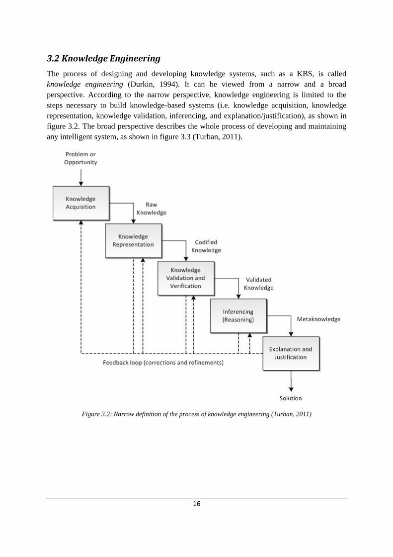
3.2 Knowledge Engineering
The process of designing and developing knowledge systems, such as a KBS, is called
knowledge engineering (Durkin, 1994). It can be viewed from a narrow and a broad
perspective. According to the narrow perspective, knowledge engineering is limited to the
steps necessary to build knowledge-based systems (i.e. knowledge acquisition, knowledge
representation, knowledge validation, inferencing, and explanation/justification), as shown in
figure 3.2. The broad perspective describes the whole process of developing and maintaining
any intelligent system, as shown in figure 3.3 (Turban, 2011).
Figure 3.2: Narrow definition of the process of knowledge engineering (Turban, 2011)

17
Figure 3.3: Broad definition pf the process of knowledge engineering (Durkin, 1994)
Both figure 3.2 and 3.3 may be interpreted as if the development process is sequential. In
practice though, the development phases are often performed in parallel. Furthermore, the
development process of a KBS is highly iterative and incremental. As new information
emerges during the development process there will almost certainly be need of refinements of
earlier tasks. The system incrementally evolves from one with limited ability to one with
increasing capability due to improvements of knowledge and problem-solving skills (Durkin,
1994).
3.2.1 Knowledge Acquisition
Knowledge acquisition is the collection, transfer and transformation of knowledge from
knowledge sources to a computer program. Knowledge can be acquired from sources such as
books, databases, pictures, articles and sensors, as well as human experts. Knowledge

18
acquisition from human experts specifically, is often called knowledge elicitation. The person
interacting with experts to elicit their knowledge is called a knowledge engineer (Turban,
2011). To accurately capture an expert´s understanding of a problem is, by its nature, a
complex task (Durkin, 1994). It often poses the biggest challenge in the development of a
knowledge-based system (Durkin, 1994; Byrd, 1995). The manual methods of knowledge
elicitation include interviewing, tracking the reasoning process, and observing. These methods
are slow, expensive and sometimes inaccurate. Therefore, semi-automated and fully
automated methods have been developed to acquire knowledge. However, the manual
methods of knowledge elicitation still dominate in real-world projects (Turban, 2011).
The following factors contribute to the difficulties in knowledge acquisition from experts and
its transfer to a computer:
Experts may not know how-, or may be unable to articulate their knowledge.
Experts may provide incorrect knowledge.
Experts may lack time or may be unwilling to cooperate.
Complexity of testing and refining knowledge is high.
Methods for knowledge elicitation may be baldy defined.
System developers often tend to collect knowledge from one source, but the
relevant knowledge may be scattered across several sources.
Knowledge collected may be incomplete.
Knowledge collected may be inconsistent.
Difficulties to recognize specific knowledge when it is mixed up with irrelevant
data.
Experts may change their behavior when they are observed or interviewed.
Problematic interpersonal communication factors may affect the knowledge
engineer and the expert (Durkin, 1994; Turban, 2011).
3.2.2 Knowledge Representation
Once the raw knowledge is acquired, it must be represented in a format that is understandable
by both humans and computers, and of course, without affecting the meaning of the
knowledge. Several knowledge representation methods exist: heuristic rules, semantic
networks, frames, objects, decision tables, decision trees, and predicate logic (Durkin, 1994;

19
Turban, 2011). Heuristic rules, which is the most popular method (Turban, 2011), is
conditional statements, usually in the form IF-THEN, that links given conditions to a
conclusion. A KBS that represents knowledge with heuristic rules is also called a rule-based
system, which will be further described in section 3.3. An example of another approach is to
use frames to relate an object or item to various facts or values. Expert systems making use of
frames are also called frame-based expert systems, and are ideally suited for object-
programming techniques (Abraham, 2005).
3.2.3 Knowledge Verification and Validation
The acquired knowledge needs to be evaluated for quality. This activity must be repeated each
time the prototype is changed (Turban, 2011).
Verification and validation of knowledge is a central theme of this thesis and is presented in
section 3.5.
3.2.4 Inferencing
The inferencing is about how the system shall control and reason about the knowledge.
Forward chaining and backward chaining are two different inferencing techniques. The choice
of inferencing technique shall be made by studying how the experts solve and reason about
the problem (Durkin, 1994).
Forward chaining is appropriate when the expert(s) first collect information about a problem
and then try to draw conclusions from it. In other words, the data is driving the reasoning
process. Another indication that this approach is suitable is if the amount of data is far smaller
then the number of solutions (ibid).
Backward chaining is appropriate when the expert(s) first considers some conclusions, and
then attempts to verify it by looking for supporting information. In this situation, the main
concern of the expert(s) is about proving some hypothesis or recommendation. Also, if the
number of conclusions is much fewer than the amount of possible data, then a backward
chaining approach might be the most suitable inferencing technique (ibid).
Another way of helping the knowledge engineer choose both the knowledge representation
technique and inferencing technique is to review what have been done in the past, in similar
projects with successful outcomes. For example, diagnostic systems are usually backward
chaining, while control systems are usually forward chaining (ibid).

20
3.2.5 Explanation and Justification
The last component implemented is the explanation and justification capability, which adds
to the interactivity with the users. This component has several purposes (Turban, 2011):
Uncover the defects and limitations of the knowledge base to the user (i.e. manual
debugging of the system by the knowledge engineer).
Explain situations that were not anticipated by the user.
Satisfy social and psychological needs by helping the user to feel confidence about the
actions of the system.
Reveal the underlying assumptions of the system´s operations to both the user and
knowledge engineer.
Allow the user to test and predict the effects of changes on the system (Turban, 2011).
The explanation and justification component is in general designed and implemented with the
ability to answer questions such as how a certain conclusion was derived by the system, or
why a piece of information is needed (ibid).
3.3 Knowledge Represented by Rules
3.3.1 Rule-Based Systems
A rule-based system is a system in which knowledge is completely represented by rules in the
form of IF-THEN (Turban et al, 2007), such as:
IF situation X is TRUE
THEN action Y
A knowledge-based system using rules for the knowledge representation in the knowledge
base is often called a rule-based expert system (Durkin, 1994).
Rule-based systems evolved from the production systems (Buchanan & Duda, 1982). This
was a human problem-solving model developed by Newell and Simon at Carnegie-Mellon
University (CMU), during the 1960s. The production system represent a human’s long-term
memory as a set of situation-action rules called productions, and the short-term memory as a
set of situations or specific information about a problem. The idea behind the production
system is that humans solve some problem using a set of productions from their long-term
memory, which apply to a given situation stored in their short-term memory. The situation

21
causes some productions to be executed and the resulting action is added into the short-term
memory as shown in figure 3.4. This process is similar to human reasoning – to infer new
information from known information (Durkin, 1994).
Figure 3.4: The production system model (Durkin, 1994)
The main components of a rule-based system, as in general knowledge-based systems, are a
knowledge base, an inference engine, a user interface and an explanation facility. Like any
other tool, a rule-based system has its advantages and disadvantages.
Advantages
For many problems, IF-THEN type statements are a natural expression of humans’ problem-
solving knowledge. In a suitable problem domain, a rule-based approach for developing
knowledge-based systems simplifies the knowledge capture process for the knowledge
engineer. Another advantage is that a rule is an independent piece of knowledge, which easily
can be reviewed, verified and checked for consistency. Furthermore, the system will only
execute those rules that are relevant to the problem. Often a rule base consists of a big number
of rules, capable of dealing with a number of problem issues. Based on discovered
information, the rule-based system can decide which set of rules to use in order to solve the
problem. Rule-based systems are also well-suited for incorporation of heuristic knowledge. A
human expert is often skillful in using rules-of-thumb, or heuristics, to solve a problem
efficiently. With heuristic rules the system can efficiently control the search space of the
knowledge base. Finally, for many problems, the problem-solving human expert often utilizes
knowledge with some degree of uncertainty, i.e. level of belief. In other words, with the
available information, the expert cannot reach a conclusion with complete certainty (Durkin,
1994). There are several techniques to capture this uncertainty relationship with rules, which
will be presented in section 3.4.
Disadvantages
A rule-based approach for knowledge representation causes high demands of strict and
consistent coding. The presence of syntactical- and semantic errors may cause poor

22
conclusions drawn by the system, which will be discussed in chapter 3.5. Furthermore, the
number of rules in a knowledge base can grow very large, and rules are allowed to be placed
anywhere in the knowledge base. Therefore it is often difficult during debugging and testing
to trace the logical relationship between rules in an inference chain. A disadvantage of
forward-chaining rule-based systems is that systems with a large set of rules can be slow
during execution. The system needs to scan the complete set of rules to determine which rules
to apply, which can cause slow processing times. This is particularly problematic for real-time
applications. Lastly, a disadvantage of rule-based systems is that some knowledge is hard to
capture in the IF-THEN format, making rule-based system implementation unsuitable for
certain knowledge domains (Durkin, 1994).
3.3.2 Business Rules and Rule Engines
Business rules have been proclaimed to be a new and exciting development in the Business
Intelligence (BI) field (Watson, 2009). Business rules is an alternative for organizations where
the business policies, procedures and business logic are too dynamic to be managed
effectively in conventional software application source code. As in conventional rule-based
systems, business rules are expressed as IF-THEN statements. Rule engines, similar to the
inference engine, interprets the business rules and acts as a tool for decision making in
applications with highly dynamic business logic (Mahmoud, 2005).
Business rules claims to have the following advantages:
Policies represented by business rules are easily communicated and understood.
Business rules bring a high level of independency compared to conventional
programming languages.
Business rules separate the knowledge from its implementation logic.
Business rules can be changed without changing the source code (ibid).
The similarities between business rule engines and rule-based systems make it legitimate to
view business rules, rather than a new technology, as a new application of the concepts of
rule-based systems. This development is an example of the movement from stand-alone rule-
based systems to embedded systems, that is, systems part of an overall conventional software
package, forecasted by Metaxiotis & Psarras (2003).
3.4 Inexact Reasoning in Knowledge-Based Systems
The design theory, and artifact, presented in this thesis, focus on verification of the rule-base
of a KBS utilizing inexact reasoning. Therefore, this section provides a background to inexact

23
reasoning theory. Emphasis is on certainty factors, a common method of inexact reasoning.
Alternative techniques are presented as well.
For many problem domains, knowledge-based systems have to adopt inexact reasoning. The
reason is, in many problem solving situations, human experts cannot simply conclude true or
false. The expert is in these situations required to make judgments when solving a problem.
The presence of uncertainty can be caused by several reasons. The available information may
be dubious or incomplete, or some of the knowledge for interpreting the information may be
unreliable (Durkin, 1994). The expert may also face situations where several outcomes are
possible for the same information at hand (Turban et al, 2007). For example, how can a user
of a medical diagnosis knowledge-based system answer the following question with complete
certainty?
Does the patient have a severe headache?
It is unlikely that a user would comfortably conclude this as either completely true or false,
because the question is subjective of nature and therefore require the user to make a judgment
(Durkin, 1994). Uncertain reasoning in complex problem domains requires tacit knowledge
acquisition from experts with long experience. Experience includes intuitions, values and
beliefs (Awad & Ghaziri, 2003).
There are several approaches to apply inexact reasoning in knowledge-based systems, each
technique have its advantages and drawbacks.
3.4.1 Statistical Probabilities
Probability theory might seemingly be the most convenient approach because it is
scientifically sound. Elementary statistics in the form of Bayes’ theorem can be used to
weight uncertain parameters and conclusions in knowledge-based systems with a probability
value between 0 and 1. However, this approach is often limited by practical difficulties; the
lack of data to adequately ―estimate the a priori and conditional probabilities used in the
theorem‖ (Buchanan & Shortliffe, 1984). Even if data is available, it can be time consuming
estimating statistical probabilities. Therefore this technique may be an inconvenient choice for
KBS projects with limited resources (Durkin, 1994). Other statistical approaches to
accommodate uncertainty in KBS are probability ratios and the Dempster-Shafer theory of
evidence (Turban, 2011).
3.4.2 Certainty Factors
Certainty factors (CF’s) is the most commonly used method to represent inexact reasoning in
knowledge-based systems (Turban, 2011). It is based on the concepts of belief and disbelief.

24
CF’s is used, like statistical probability, to weight the system’s belief that a parameter or
hypothesis is true or false. This technique was created during the MYCIN project in the mid-
late 1970s, during the development of a medical diagnosis rule-based expert system at
Stanford University (Buchanan & Duda, 1982).
CF’s is a heuristic inexact reasoning technique that has its basis in statistical probabilities.
However, CF’s should not be interpreted as probabilities, as the defining equations are more
ad hoc, and designed to mimic human inexact reasoning. A central idea in the theory is that ―a
given piece of evidence can either increase or decrease an expert’s belief in a hypothesis‖
(Durkin, 1994). The measure of belief (MB) is a ―number that reflects the measure of
increased belief in a hypothesis H based on evidence E‖. Conversely, the measure of disbelief
(MD) is a ―number that reflects the measure of increased disbelief in a hypothesis H based on
evidence E‖ (Durkin, 1994). MB and MD can be assigned a number in the interval 0 ≤ MB,
MD ≤ 1. A certainty factor value can be derived from MB and MD, as shown in table 3.1, and
was first calculated as:
CF = MB – MD
but later changed to:
CF = MB – MD / (1 – min(MB,MD))
CF values are in the interval -1 to 1.
Probabilities
MB, MD, CF Values
Hypothesis True
P(H|E) = 1
MB = 1
MD = 0
CF = 1
Hypothesis False
P(~H|E) = 1
MB = 0
MD = 1
CF = -1
Lack of evidence
P(H|E) = P(H)
MB = 0
MD = 0
CF = 0
Positive evidence
P(H) < P(H|E) < 1
MB > 0
MD = 0
CF = MB
Positive evidence
P(H) < P(H|E) < 1
MB > 0
MD > 0
MB > MD
CF = MB – MD / (1 – MD)
Negative evidence
0 < P(H|E) < P(H)
MB = 0
MD > 0
CF = -MD

25
Negative evidence
0 < P(H|E) < P(H)
MB > 0
MD > 0
MB < MD
CF = MB – MD / (1 – MB)
Table 3.1: Relationships between P and MB, MD and CF (Durkin, 1994)
Certainty factors are not probabilities, and not scientifically reliable measures. Instead they try
to informally represent humans’ degree of belief if the evidence is true in a knowledge-based
system. For example, see the uncertain statement below:
―It will probably rain today‖
With certainty theory, the statement above can be rewritten as an exact term, when adding an
appropriate CF value to it, as shown below:
―It will rain today‖ CF 0.6
Uncertain statements is valued with a CF value in the interval -1.0 to 1.0, as illustrated in
table 3.2 that shows a typical mapping of CF values for uncertain statements (Durkin, 1994).
Uncertain term CF
Definitely not -1.0
Almost certainly not -0.8
Probably not -0.6
Maybe not -0.4
Unknown -.2 to .2
Maybe 0.4
Probably 0.6
Almost certainly 0.8
Definitely 1.0
Table 3.2: CF value interpretation (Durkin, 1994)
Uncertain rules
Just like statements, CF values can be attached to rules to represent the uncertain relationship
between the premise and the conclusion of the rule. The simple structure for representing
uncertain rules with certainty factors is as follows:
IF premise X THEN conclusion Y CF(RULE)

26
The value of CF(RULE) represent the level of belief of conclusion Y given that premise X is
true:
CF(Y,X) = CF(RULE)
The following rule is an example of a rule implemented with the certainty model:
Rule1
IF There are dark clouds
THEN It will rain
CF = 0.8
According to table 3.2, this rule can be expressed in natural language as:
―If there are dark clouds then it will almost certainly rain.‖
If the premise in a single premise rule as above is associated with uncertainty, the total belief
of the conclusion, given the premise, is calculated by simply multiplying the CF of the
premise with the CF of the rule, as in table 3.3. Therefore, if the premise in rule1 above is
estimated to have a CF of 0.5, then the belief of the conclusion, given the premise, is:
CF(Y,X) = 0.5 * 0.8 = 0.4
Rule Formula
Rule CF(rule)
IF X CF(premise)
THEN Y
CF(Y,X) = CF(premise) * CF(rule)
Table 3.3: Formula for estimating CF of conclusions
The conclusion of rule 1 would then be expressed, according to table 3.2 as:
―It will maybe rain‖
If the rule has multiple premises associated with uncertainty, a combined CF of the premises
needs to be estimated (Durkin, 1994). Multiple premises are connected by Boolean operators
AND, OR, also called conjunction (x˄y), and disjunction (x˅y) (Boole, 2003). How to
estimate the CF of two combined premises depends on the Boolean operator, as shown in
table 3.4.
Multiple premise conditions Formula IF P1 CF(P1)
AND P2 CF(P2)
THEN C
CF(P1,P2) = min{CF(P1),CF(P2)]
IF P1 CF(P1)
OR P2 CF(P2)
THEN C
CF(P1,P2) = max{CF(P1),CF(P2)}
Table 3.4: Formulas for estimating CF of multiple premises (Durkin, 1994)

27
The following example show the estimation of CF(conclusion, premises) of a rule with
multiple premises, according to table 3.3 and table 3.4:
Rule2
(
IF P1 CF(0.6)
AND P2 CF(0.4)
)
OR P3 CF(-0.6)
THEN C
CF(Rule2)= 0.8
CF(P12) = CF(P1,P2) = min{0.6,0.4} = 0.4
CF(P12,P3) = max{0.4,-0.6} = 0.4
CF(C) = 0.4 * 0.8 = 0.32
In a rule base it is common to have multiple rules showing the same conclusion. It is the same
as to strengthen a hypothesis by looking for multiple supporting evidences. Intuitively, if two
sources support a hypothesis with some degree of belief, our confidence in the hypothesis
would increase. The CF model makes use of a technique called incrementally acquired
evidence to combine values of belief and disbelief established by rules showing the same
conclusion. There are different formulas for combining two rules CF of conclusions,
depending on the condition of the CF, as shown in table 3.5. The resulting CF of a
combination can of course never exceed 1, or fall below -1.
CF values can be used to increase the heuristic search of the rule base. The system can be
designed to make a best-first search that pursue the rules with the highest CF first, that is, the
most promising rules. CF values can also be used to terminate the search. If the CF of a
hypothesis falls below a pre-set value, the system will reject this hypothesis (Durkin, 1994).
Table 3.5: Formulas for combining two certainty factors for the same conclusion
Limitations of certainty theory
Certainty theory is a simple and practical approach for managing inexact reasoning in
knowledge-based systems. The technique is suited for problems that do not have a strong
statistical basis. However, the model´s lack of formal foundation brings about certain
limitations for the rule base developer. There are two problems with deep inference chains in
rules with certainty factors. The first problem is caused by the distantness to conditional
CF1 and CF2 conditions Formula
CF1 and CF2 > 0 CF comb(CF1,CF2) = CF1 + CF2 * (1 - CF1)
One of CF1 and CF2 < 0 CF comb(CF1,CF2) = CF1 + CF2 / (1 – min{|CF1|,|CF2|})
CF1 and CF2 < 0 CF comb(CF1,CF2) = CF1 + CF2 * (1 + CF1)
Table 6
Table 7

28
probability theory. To illustrate the problem, consider RULE1 and RULE2, where conclusion
of RULE1 supports the premise in RULE2:
RULE1 RULE2
IF A IF B
THEN B CF=0.8 THEN C CF=0.9
According to table 3.3, the certainty theory model ―propagates the certainty value through an
inference chain as independent probabilities‖ (Durkan, 1994):
CF(C,A) = CF(C,B) *CF(B,A)
The second problem with deep inference chain is the inherent decrease of belief of a
hypothesis, exemplified by RULE1 and RULE2 where the premise A in RULE1 is set to have
CF(A) = 0.8:
RULE1 RULE2
IF CF(A) = 0.8 IF CF(B) = 0.64
THEN CF(B) = 0.8*0.8 = 0.64 THEN CF(C) = 0.9*0.64 = 0.58
So in a deep inference chain, the CF of the top-level hypothesis will converge towards 0,
resulting in a very low belief in the hypothesis. Therefore, deep inference chains should be
avoided in a KBS using certainty theory to deal with inexact reasoning.
If a rule base consists of many rules concluding the same hypothesis, the value will converge
towards 1 (see table 3.5). An example of this problem is where a number of experts all maybe
believe a hypothesis is true, the KBS will combine the belief of sources and conclude that the
hypothesis is definitely true. Therefore, many rules supporting the same conclusion should be
avoided.
Rules with multiple premises in conjunctive form, that is, premises connected by the Boolean
operator ARE, may cause inappropriate CF estimations. As shown in table 3.4, the certainty
model simply takes the minimum of the premises CF value and multiplies it with the CF value
of the rule. The example below show a problematic estimation of CF value of a hypothesis:
IF Sky is dark CF = 1.0
AND Wind is increasing CF = 1.0
AND Temperature is dropping CF = 0.2
THEN It will rain CF 0.9
CF(It will rain) = min{0.2,1.0,1.0}×0.9 = 0.18
The example above will conclude that I don´t know if it is going to rain. Two of the premises
has the highest belief, but it is the third premise´s low CF that determine the low confidence
of the hypothesis. In some applications, this is acceptable. In applications where it is not, rules
with multiple conjunctive premises should be considered to be rewritten into multiple rules
with fewer premises with the same conclusion (Durkin, 1994).

29
3.4.3 Fuzzy Logic
Fuzzy logic is an approach to represent fuzzy knowledge and information in KBS, introduced
by Zadeh (1965). A fuzzy expert system is an expert system that uses a set of fuzzy
membership functions and rules, to reason about data (Abraham, 2005).
There are inexact fuzzy knowledge and information that certainty theory and statistical
probabilities are not able to represent in KBS. Fuzzy concepts, such as tall, good, and hot,
form the substance of a significant part of the natural language. This fuzziness occurs when
the boundary of a piece of information is not clear. Uncertainty, explained in section 3.4.2,
occurs when you cannot be absolute certain about a piece of information. Uncertainty and
fuzziness may occur simultaneously in some situations, such as in the statements below:
―Paul is rather tall‖. (0.8)
―If the price is high, then the profit should be good‖. (0.9)
The certainty factors in this example are the values 0.8 and 0.9. ―Rather tall‖, ―high‖, and
―good‖ are fuzzy terms. Furthermore, the uncertainty itself can sometimes be fuzzy, such as in
this statement:
―Paul is very tall‖. (around 0.7)
―Around 0.7‖ is a fuzzy certainty factor, and ―very tall‖ is a fuzzy term.
To illustrate how fuzzy logic can deal with fuzzy concepts and approximate reasoning, the
fuzzy term tall can be defined by the fuzzy set in table 3.6.
Height (cm) Grade of membership (possibility value)
140 0.0
150 0.1
160 0.2
170 0.5
180 0.8
190 1.0
200 1.0
Table 3.6: Fuzzy set of the fuzzy term ”tall”
The grades of membership values in table 3.6 constitute a possibility distribution of the term
tall. The values can be bound to a number in the interval 0 to 1. The possibility distribution of
the fuzzy terms very tall and quite tall can then be obtained by applying arithmetic operations

30
on the fuzzy set for tall. For example, to obtain the fuzzy set for very tall, each possibility
value in table 3.6 can be squared, to form a new fuzzy set as in table 3.7.
Height (cm) Grade of membership (possibility value)
140 0.0
150 0.01
160 0.04
170 0.25
180 0.64
190 1.0
200 1.0
Table 3.7: Fuzzy set of the fuzzy term ”very tall”
The fuzzy logic approach should be considered for KBS developments in problem domains
with a high presence of fuzzy data.
3.5 Verification of a Knowledge-Base
Verification of knowledge-based systems involves testing the systems reasoning capability.
More specifically, the system has to be verified if it concludes satisfying hypothesis, and if the
knowledge base consists of complete and consistent knowledge
The purpose of verification and validation is to ensure the quality of software. For knowledge-
based systems in critical-use, as well as many noncritical-use applications, the reliability of
the system must be guaranteed before employment of the system should be considered.
Knowledge-based systems is also supposed to be ―intelligent‖, if the system draws wrong
conclusions this may lead to a loss of credibility by the users. It may lead to less frequent use
of the system and in the end a complete shutdown of the knowledge-based system (Gonzalez
et al, 1993).
This thesis deals mainly with verification of rule-based expert systems but it may be
appropriate to define the distinctions between verification and validation, as this is known to
often be confused (Gonzalez et al, 1993; O’Leary et al, 1990; Preece, 2000). Verification in
software engineering (and therefore also in knowledge engineering) is the process of checking
that the system meets the specified user requirements. Validation is the process of checking
whether the software meets the actual user requirements (Preece, 2000). A well-known
characterization of the differences of V&V was formulated by Boehm (1984): ―Verification is
building the system right. Validation is building the right system‖. Preece (2000) elaborate

31
further on this view of V&V by arguing that it is unlikely to succeed in ―building the right
system‖ without ―building it right‖. Therefore verification may be a part of the validation
process. However, verification rarely makes up the whole of the validation process, because
of the commonly imposed difficulties in capturing specified user requirements.
In a knowledge-based system-engineering context, verification of the knowledge base is the
process of ensuring the quality of the knowledge base. Validation on the other hand is the
process of checking that the knowledge of the human experts is accurately represented in the
knowledge base (Preece, 2000).
Verification of the knowledge base is really a two-step process (Gonzalez et al, 1993):
Check for compliance between the knowledge base and the system specifications.
This includes for example consideration if a proper knowledge
presentation paradigm has been implemented. Also, to examine if the
user interface meets the specification and if the requirements regarding
time effectivity of the system are met.
Check for errors induced by the developers of the knowledge base.
These errors are categorized as either semantic or syntactic
inconsistencies.
Both steps are equally important to ensure the reliability of the knowledge base. However,
because Klöver, the rule based system to-be verified by the instantiated artifact, was
developed and implemented over a decade ago, the system is therefore considered to be
verified regarding compliance to the specifications. Therefore this thesis has the focus on the
second step of the verification of knowledge bases; checking for inconsistencies in the
knowledge base.
Errors introduced by the knowledge engineer during development of the knowledge base
might happen for several reasons. It might be mistakes in spelling or syntax, but errors can
also be induced because the expert´s knowledge to start with is incomplete, inconsistent, or
simply partially wrong. Moreover, the cause of the error might also be that the expert´s
knowledge has not been adequately transferred to the computer-based representation (Suwa et
al, 1982).
Syntactic and semantic inconsistencies affect the completeness and consistency of the
knowledge base. A complete and consistent knowledge base ensures that the knowledge-
based system correctly represents the experts’ knowledge, but does not imply that the system
will draw correct conclusions (Gonzalez et al, 1993). A complete knowledge base means that
it is possible to reach all conclusions that can be drawn by the inference engine. A consistent
knowledge base is free of conflicting-, identical- and subsumed rules (Suwa et al, 1982).

32
Verification of syntactic inconsistencies in a general rule base implies to check for the eight
inconsistencies displayed in figure 3.5.
Table 8
As indicated in figure 3.5, the first five of the inconsistencies affects the consistency of the
rule base, and the last three affects the completeness of the rule base.
Verification of consistency and completeness in a knowledge-base is a heuristic approach,
rather than deterministic, for two reasons. Firstly, an anomaly can be considered a potential
error – it may be an actual error, or may alternatively be intended. Secondly, some methods
for detecting anomalies are themselves heuristic, and thus do not guarantee that all
identifiable anomalies will be detected (O´Keefe & O´Leary, 1993).
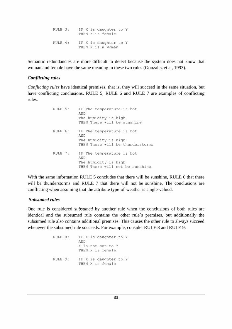
Redundant rules
Two syntactically redundant rules have identical premises as well as identical conclusions.
RULE 1 and RULE 2 are for example syntactically redundant.
RULE 1: IF X is daughter to Y
AND
Y is daughter to Z
THEN X is a grandchild to Z
RULE 2: IF Y is daughter to Z
AND
X is daughter to Y
THEN X is grandchild to Z
Both rules will succeed under the same circumstances, and will draw the same conclusion that
―X is the grandchild of Z‖.
Semantic redundancy occurs when two rules are syntactically redundant except the premises
or the conclusions have different syntax, but the meaning is the same. RULE 3 and RULE 4
are for example semantically redundant:
1. Redundant rules Consistency
2. Conflicting rules
3. Subsumed rules
4. Circular rules
5. Unnecessary IF conditions
6. Dead-end rules
7. Missing rules
8. Unreachable rules
Completeness
Figure 3.5: Syntactic inconsistencies in a rule-base
33
RULE 3: IF X is daughter to Y
THEN X is female
RULE 4: IF X is daughter to Y
THEN X is a woman
Semantic redundancies are more difficult to detect because the system does not know that
woman and female have the same meaning in these two rules (Gonzalez et al, 1993).
Conflicting rules
Conflicting rules have identical premises, that is, they will succeed in the same situation, but
have conflicting conclusions. RULE 5, RULE 6 and RULE 7 are examples of conflicting
rules.
RULE 5: IF The temperature is hot
AND
The humidity is high
THEN There will be sunshine
RULE 6: IF The temperature is hot
AND
The humidity is high
THEN There will be thunderstorms
RULE 7: IF The temperature is hot
AND
The humidity is high
THEN There will not be sunshine
With the same information RULE 5 concludes that there will be sunshine, RULE 6 that there
will be thunderstorms and RULE 7 that there will not be sunshine. The conclusions are
conflicting when assuming that the attribute type-of-weather is single-valued.
Subsumed rules
One rule is considered subsumed by another rule when the conclusions of both rules are
identical and the subsumed rule contains the other rule´s premises, but additionally the
subsumed rule also contains additional premises. This causes the other rule to always succeed
whenever the subsumed rule succeeds. For example, consider RULE 8 and RULE 9:
RULE 8: IF X is daughter to Y
AND
X is not son to Y
THEN X is female
RULE 9: IF X is daughter to Y
THEN X is female

34
Both rules have the same conclusion, and RULE 9 has only one of the two premises in RULE
8 and will always succeed whenever RULE 8 succeeds. Therefore RULE 8 is subsumed by
RULE 9.
Circular rules
A set of rules are circular if the set of rules forms a cycle. RULE 10, RULE 11 and RULE 12
are an example of circular rules.
RULE 10: IF Body temperature of X > 38 degrees Celsius
THEN X has a fever
RULE 11: IF X has a fever
AND
X has flat pink spots on his/her skin
THEN Disease of X is measles
RULE 12: IF Disease of X is measles
THEN Body temperature of X > 38 degrees Celsius
The conclusion of RULE 10 is a condition for RULE 11, the conclusion of RULE 11 is the
condition of RULE 12 and the conclusion of RULE 12 is the condition for RULE 10, thus the
rules forms a circular chain. The danger of circular rules is that it can create an infinite loop
during execution.
Unnecessary IF conditions
Two rules contain unnecessary IF conditions (premises) if the rules have the same conclusion
and if one premise in each rule contradicts one another while the rest of the premises are
identical (Nguyen et al, 1987). Consider RULE 13 and RULE 14:
RULE 13: IF It is sunshine
AND
it is summer
THEN The temperature is hot
RULE 14: IF It is not sunshine
AND
it is summer
THEN The temperature is hot
If the contradicting premises in these rules are truly unnecessary, RULE 13 and RULE 14 can
be collapsed into the following rule:
RULE 15: IF It is summer
THEN The temperature is hot
Conflicting rules and unnecessary IF conditions are very often caused by missing knowledge
or incorrect knowledge expressed within a rule. Caution should therefore be taken before
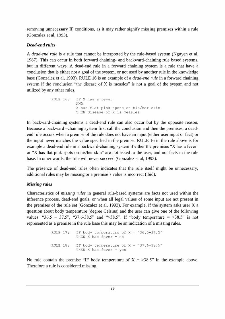
35
removing unnecessary IF conditions, as it may rather signify missing premises within a rule
(Gonzalez et al, 1993).
Dead-end rules
A dead-end rule is a rule that cannot be interpreted by the rule-based system (Nguyen et al,
1987). This can occur in both forward chaining- and backward-chaining rule based systems,
but in different ways. A dead-end rule in a forward chaining system is a rule that have a
conclusion that is either not a goal of the system, or not used by another rule in the knowledge
base (Gonzalez et al, 1993). RULE 16 is an example of a dead-end rule in a forward chaining
system if the conclusion ―the disease of X is measles‖ is not a goal of the system and not
utilized by any other rules.
RULE 16: IF X has a fever
AND
X has flat pink spots on his/her skin
THEN Disease of X is measles
In backward-chaining systems a dead-end rule can also occur but by the opposite reason.
Because a backward –chaining system first call the conclusion and then the premises, a dead-
end rule occurs when a premise of the rule does not have an input (either user input or fact) or
the input never matches the value specified in the premise. RULE 16 in the rule above is for
example a dead-end rule in a backward-chaining system if either the premises ―X has a fever‖
or ―X has flat pink spots on his/her skin‖ are not asked to the user, and not facts in the rule
base. In other words, the rule will never succeed (Gonzalez et al, 1993).
The presence of dead-end rules often indicates that the rule itself might be unnecessary,
additional rules may be missing or a premise´s value is incorrect (ibid).
Missing rules
Characteristics of missing rules in general rule-based systems are facts not used within the
inference process, dead-end goals, or when all legal values of some input are not present in
the premises of the rule set (Gonzalez et al, 1993). For example, if the system asks user X a
question about body temperature (degree Celsius) and the user can give one of the following
values: ―36.5 – 37.5‖, ―37.6-38.5‖ and ―>38.5‖. If ―body temperature = >38.5‖ is not
represented as a premise in the rule base this may be an indication of a missing rules.
RULE 17: IF body temperature of X = “36.5-37.5”
THEN X has fever = no
RULE 18: IF body temperature of X = “37.6-38.5”
THEN X has fever = yes
No rule contain the premise ―IF body temperature of X = >38.5‖ in the example above.
Therefore a rule is considered missing.

36
A dead-end goal appears when the attributes of a goal is not askable, or the goal is not
matched by a conclusion of any rules in the rule-base (Nguyen et al, 1987).
Unreachable rules
Unreachable rules are the inverse of dead-end rules described above, and likewise, differ
depending on if the system is forward chaining or backward-chaining. An unreachable rule in
a forward-chained system has a premise that will never be matched, either because of missing
rules, lack of input data, lack of facts or spelling errors. This is the equivalent of a dead-end
rule in a backward-chaining system. Conversely, in a backward-chaining rule-based system,
an unreachable rule has a conclusion that is not a goal of the system and not a condition of
another rule. The consequence will be that the rule is untraceable, which is the equivalent of a
dead-end rule in a forward chaining system (Gonzalez et al, 1993).
3.6 Prolog
Prolog stands for PROgramming in LOGic, and is a declarative logic programming language
(Johansson et al, 1989). Declarative programming means to describe what the program is
supposed to accomplish, rather than describing how it shall accomplish it. Prolog is suitable
for artificial intelligence and non-numerical programming in general, and is particularly well
suited for solving problems that involve objects and relations between objects (Bratko, 2001).
Prolog has for example been used in the following fields of applications (Johansson et al,
1989):
Natural language processing
Databases
Expert systems & knowledge-based systems
Planning
Construction of compilators
CAD (Computer Aided Design)
3.6.1 Syntax of Prolog
A program written in Prolog consists of Horn clauses. The Horn clauses are a subset of the
predicate calculus, a form of logic. A Horn clause can have the following formats (Johansson
et al, 1989):

37
Logic: x1...xn (AB1 … Bi)
Prolog logic: A B1 B2 … Bi written as A:- B1, B2 ,..., Bi (i)
A written as A. (ii)
A written as ?- A. (iii)
In (i) the relation A is true if all the relations B1 up to Bi are true. This means that the
conclusion A is true if the conditions B1 and B2 and … and Bi are satisfied. (ii) means that
the relation A is always true. (iii) is the form for a question to the system whether the relation
A is true. The answer is yes if A can be fulfilled and if not the answer is no.
The three possible formats of Horn clauses, explained above, are rules (i), facts (ii), and
questions (iii) (Johansson et al, 1989).
Prolog clauses such as:
offspring(X,Y) :- parent(Y,X).
head body
are called rules, and the example above can be read as:
For all X and Y,
X is an offspring of Y
if Y is a parent of X.
Rules always have:
a condition part (the right-hand side of the rule) and
a conclusion part (the left-hand side of the rule).
The conclusion part is also called the head of a clause, and the condition part the body of a
clause (Bratko, 2001).
A daughter relation can be described in Prolog by the following rule:
daughter(Y,X) :- parent(X,Y), female(Y).
As in the example above, a comma between two conditions indicates the conjunction of the
conditions (Boolean operator AND), meaning that both conditions have to be true (Bratko,
2001).
Another offspring relation can be described in Prolog by the following rule:
offspring(Y,X) :- father(X,Y); mother(X,Y).

38
As in the example above, a semicolon between two conditions indicates the disjunction of the
conditions (Boolean operator OR), meaning that at least one of the conditions have to be true
(Bratko, 2001).
A fact about the parent relation can be written in Prolog as:
parent(susan,karl).
and is always unconditionally true.
When a program has been loaded into a Prolog system, questions can be communicated to the
Prolog system by, for example, typing into the terminal (Bratko, 2001):
?- offspring(karl,susan).
With the following program consisting of two clauses; one rule and one fact:
offspring(Y,X) :- parent(X,Y).
parent(susan,karl).
Prolog´s answer to the question above is:
yes
because the goal offspring(karl, susan) was satisfiable, i.e. proved true.
For more information regarding Prolog, see Appendix 2.
3.6.2 Meta-Programming
Due to its symbol-manipulation capabilities, Prolog is a powerful language for meta-
programming. A meta-program is a program that takes other programs as data. Examples of
meta-programs are interpreters and compilers. A meta-interpreter is a particular kind of meta-
program; an interpreter for a language written in that same language. So a Prolog meta-
interpreter is an interpreter for Prolog, itself written in Prolog (Bratko, 2001).
Prolog implementations, such as SICStus Prolog (SICStus Prolog, 10 October 2011),
provides a set of built-in predicates usable for meta-programming (Bratko, 2001).
The following are some of the built-in predicates to-be used for the implementation of the
artifact:
clause/2
The built-in method clause with the two arguments Head and Body retrieves a clause of a
rule from a consulted program. Head is the conclusion part of the clause and Body is its

39
condition part. The condition part of a rule can contain one or several premises. If the
condition part is made-up by several premises, then they are retrieved as a pair (Bratko,
2001):
Body = (FirstPremise, OtherPremises)
bagof/3, setof/3 and findall/3
These three methods are used for retrieving a group of objects, collected into a list (Bratko,
2001). For example, the goal bagof with three arguments X, P and L will produce the list L
of all the objects X, where the condition(s) P is satisfied.
The only differences between bagof, setof and findall are that setof returns a list which
is ordered, and without duplicated items. The findall difference with respect to bagof in
that it succeeds even when no objects satisfies the condition, and returns an empty list, where
bagof will fail (setof as well) (Bratko, 2001).
assert/1, retract/1 and retractall/1
A Prolog program can be viewed as a relational database, i.e. a specification of a set of
relations. In Prolog, the specification of relations is partly explicit (facts), and partly implicit
(rules). The built-in predicates assert, retract and retractall makes it possible to update
this database during the execution of a program (Bratko, 2001).
The goal
assert(X)
always succeeds, and adds a clause X to the database. The goal
retract(X)
deletes a clause X from the database. The goal
retractall(X)
deletes all instances of clauses X from the database (ibid).
3.7 Klöver
The artifact will be customized to debug the knowledge-base of Klöver. Therefore, a general
presentation of this specific program is appropriate. This section is delimited to explain

40
general aspects of Klöver, and entities of Klöver - related to the artifact. Information about the
knowledge-base in Klöver is further elaborated in section 4.3.1.
Klöver is a knowledge-based system, developed in the late 80s by postgraduate students
Anneli Edman and Lena Sundling at the Department of Computer Science of Uppsala
University, Sweden (Edman et al, 2000). This program is a backward-chaining KBS utilizing
certainty factors. The knowledge-base is composed by rules in IF-THEN format, therefore the
program satisfy the definition of a rule-based system. Klöver is coded in Prolog and has been
implemented, in different versions, to run on SICStus Prolog and LPA Prolog (ibid).
The system Klöver has successfully been implemented in several problem domains, for
example:
As an educational KBS for environment protection (Edman and Sundling, 1991).
As an ES for analyzing environmental consequences (Håkansson and Öijer, 1993).
As an intelligent rule editor supporting the knowledge acquisition process (Håkansson
et al, 2000).
As a decision support system for teachers of drug abuse (Jeppesen and Lundén, 2005).
Klöver is also used in the education at the department of Informatics and Media, Uppsala
University, in the master course Knowledge Management.
3.7.1 Architecture of Klöver
According to Edman et al (2000), Klöver has the following components (see figure 3.6):
The Database stores the results from the latest execution of Klöver, i.e. user input,
conclusions drawn by the system, and rejected hypothesis.
The Knowledge-base consists of rules, information on rules and information related to
the conclusions.
The Question-base contains all the system's issues and information that is linked to
these.
The Interpreter will draw conclusions based on rules and user input, dealing with
uncertainty management and presentation of results. The interpreter also adds up the
menu bar.
The Question generator handles the initial questioning.
The explanation mechanism handles How-explanations and Why-definitions.

41
Figure 3.6: Illustration of collaboration between different components in Klöver
a) Questions generated by the question generator.
b) Questions generated by the interpreter from rules.
c) Any supplementary questions to the issues in b.
d) Reading and storage of the responses.
e) Interpretation of the rules.
f) Reading and storage of the responses.
g) Reading of rules for explanations.
h) Reading of information on how the rules were used.
3.7.2 Representations in the Knowledge Database
Klöver is a rule-based system. The rules generally have the following form:
rule(Number,Object, Attribute, Certaintyfactor):-
condition1,

42
condition2,
...
condition_n.
The certainty factor may have a value between -1000 (definitely not true) and 1000 (definitely
true). The conditions are connected with and (,), or (;) and negation (\ +). The conditional
clauses can be arbitrary Prolog clauses or of the type check. Conditions of the latter kind will
be interpreted by the system´s inference mechanism (Edman et al, 2000).
3.7.3 Inference Mechanism
The inference mechanism is a traditional, backward chaining depth-first interpreter. All
parameters declared as goal parameters, i.e. goal_conclusions, in the system will be examined
in the order they are declared. The goal parameters are normally set by the rules, which in its
part have conditions. These conditions will then be the system's new targets to explore, etc.
The parameters are examined in two steps, first the system tries to find the value of the
parameter and then decide whether the conditions set are valid (Edman et al, 2000).
In order to find a value for a parameter there are several methods. These are examined in the
following order:
If it is a user-given response.
If it is a drawn conclusion.
If it is an unanswered question, the question itself and any follow-up questions will be
asked and the answers stored.
If there are rules for the object they will be examined and the conclusion will be
stored.
When the parameter is set to a value in any of these steps, the condition is examined. All goal
parameters are unconditional, i.e. they always succeed if they are set to a value (ibid).
Searching the rules for an object is based on lists of rules that will set every object. Each rule
is examined and if its condition goes through the inference mechanism, the conclusion is
drawn in the head of the rule. The certainty factor of an object´s attribute is updated for each
rule that proves satisfiable for that object (ibid).
See Appendix 1 for more information regarding Klöver.

43
Development of the Design Theory
The design theory and its instantiation are presented in this chapter. Firstly, the requirements
for the artifact are introduced. Secondly, the design of a verification tool for a KBS utilizing
certainty factors is presented, along with information regarding the specific design of the
artifact. Thirdly, the process of implementing the design product is described, followed by
overall presentation of the final prototype of the artifact. Finally, the results from the
customer evaluation of the prototype are presented.
4.1 System Requirements
The specific system requirements of the artifact were elaborated in collaboration with the
customer; a researcher at the department of Informatics and Media at Uppsala University,
Sweden. The formalized requirements for the debugger of Klöver are as follows:
The artifact shall be integrated with the knowledge-based system Klöver.
The artifact shall be able to dynamically detect syntactical anomalies in different
knowledge-bases implemented in Klöver.
The artifact shall not modify the knowledge base.
The artifact shall be able to efficiently detect inconsistencies in big rule-bases.
The artifact shall provide the knowledge engineer with clear and understandable
information about the inconsistencies found in the rule base.
The usability of the artifact shall be high enough for a student of knowledge-based
systems to be able to make use of the artifact.
As shown, a majority of the requirements concerned the functionality of the artifact. The
system requirements will be the foundation for the customer evaluation of the prototype of the
artifact, presented in section 4.5.
Some of the requirements above are presumably applicable for developments of verification
tools for KBS in general:
The verification tool shall be able to dynamically detect syntactical anomalies in
different knowledge-bases implemented in the KBS.
The verification tool shall not modify the knowledge base.
The verification tool shall be able to efficiently detect inconsistencies in big rule-
bases.

44
The verification tool shall provide the knowledge engineer with clear and
understandable information about the inconsistencies found in the rule base.
4.2 Design
A key topic of the design theory presented in this master thesis is to highlight and elaborate
the design process of an artifact with the ability to verify a rule-base regarding completeness
and consistency. This process includes an analysis of the rule-based system to-be verified.
The purpose of this analysis is to identify constructs and entities in the rule-based system,
affecting the verification of completeness and consistency. The results of this analysis are
presented in section 4.2.1.
Based on the results in 4.2.1, the next step in the design process is to customize the general
definitions of the inconsistencies of consistency and completeness to Klöver, the inexact-
reasoning rule-based system to-be verified by the artifact. The results of this process are
presented in section 4.2.2.
4.2.1 The Rule-Base in Klöver
The design and implementation of a rule-base influences the development of a verification
tool customized to verify this specific rule base. The specific rule-base may also affect the
appearance and effects of inconsistencies regarding completeness and consistency. Therefore,
identified constructs and entities affecting the interpretation of the rule-base in Klöver will be
presented below.
rule/4
A rule in Klöver is written in the following format:
rule(Rule_number, Object, Attribute, Certainty_factor):-
check(Premise A),
check(Premise B).
As shown, the conclusion of a rule is defined before the conditions, because Klöver is a
backward-chaining system. The predicate rule has four attributes; Rule_number is instantiated
to an integer, Object can be interpreted as a conclusion of the system, Attribute represents
an attribute of the object Object, and Certainty_ factor represents the system belief in the
attribute of the object. The premises of the rule are arguments to the predicate check(), which
return true if the premise is satisfiable, otherwise false.
rule_info/2

45
rule_info(Object, List_of_rulenumbers) is a predicate assigned to control the order of
the rules during execution. An instantiation of rule_info/2 is supposed to be declared for
every unique Object in the rule base. Furthermore, the rule numbers of all rules with the
same Object in the rule-base has to be represented in the attribute List_of_rulenumbers, in
rule_info/2. See the example below:
rule_info(Object1, [1,2,3,4,5]).
rule_info(Object2, [6,7,8]).
Two instantiations of rule_info/2 have been declared. During execution, the inference
engine will call the top predicate of rule_info/2. Rule 1-5 with the Object1 will be
executed in that order. The inference engine then calls the second structure and executes the
rules 6 to 8 with the Object2.
As shown, rule_info/2 both controls the order of rules during execution, as well as the order
of the objects during execution.
goal_conclusions/1
goal_conclusions(List_of_objects) is a structure containing all the conclusions, i.e. the
objects, the system will conclude. Despite the name of the predicate, the conclusions in
goal_conclusion/2 do not have to be goals of the system, but may instead be conditions of
other conclusions. During execution of the rule-base, goal_conclusion/1 is called by the
inference engine to identify the instantiations of rule_info/2.
4.2.2 Inconsistencies in the Rule-Base of Klöver
A major part during the design of a tool verifying a rule-base is to identify how
inconsistencies of completeness and consistency may appear in the rule base, and what effects
they bring upon. In this section, identified possible inconsistencies in the rule-base of Klöver
are presented. Furthermore, the differences between the identified inconsistencies in Klöver
and the inconsistencies in exact-reasoning rule-based systems (see section 3.5.1) are presented
as well.
The general method of verifying a rule base of completeness and consistency is the process of
identifying the eight inconsistencies described in section 3.5 (see figure 3.5).
For verification of the rule-base in Klöver, great consideration about the relevancy,
appearance, definition, and effects of each inconsistency was required. The results of this
process are presented below.
Redundant rules in Klöver

46
Redundant rules are generally defined as rules with identical conclusions and premises. In a
KBS utilizing certainty factors, the CFs of the rules are not required to be identical to indicate
redundancy. Redundant rules will result in defective estimations of the system´s belief of goal
conclusions drawn by the system. Therefore, the validation tool will be designed to detect
these inconsistencies in Klöver.
Conflicting rules in Klöver
The inconsistency of two conflicting rules is generally defined as two rules with identical
premises, yet separate conclusions, previously explained in section 3.5.1. However, this is not
an inconsistency in an inexact reasoning rule-based system. From definition, inexact
reasoning technique is to be applied for problem domains where a problem-solver faces
situations where several outcomes are possible for the same pieces of information. The
validation tool for Klöver will therefore not warn the rule-base developer about these rule
structures.
Subsumed rules in Klöver
The inconsistency regarding subsumed rules in rule-based systems utilizing certainty factors
is questionable. In section 3.5.1, subsumed rules in general rule-based systems were defined
as ―a rule is considered subsumed by another rule when the conclusions of both rules are
identical and the subsumed rule contains the other rule´s premises, but additionally the
subsumed rule also contains additional premises. This causes the other rule to always succeed
whenever the subsumed rule succeeds‖. In a rule-based system such as Klöver, the format of
subsumed rules can be considered acceptable, and even beneficial for many problem domains.
Consider the example below:
RULE 2, CF = 0.6 IF premise(A)
AND
premise(B)
THEN Conclusion(C)
RULE 3, CF = 0.05 IF premise(A)
THEN Conclusion(C)
RULE 4, CF = 0.05 IF premise(B)
THEN Conclusion(C)
In inexact reasoning decision-making, a decision-maker may confront situations where
multiple supporting evidences together strongly indicate a conclusion, but separately, the
evidences are much lesser indicators of the same conclusion. In a rule-based system utilizing
certainty factors, it can be motivated to use the rule structure shown in the example above, to
represent these knowledge relationships and to aggregate the CFs of the conclusion.
Conversely, the same applies for situations as above, where the only difference is that the
evidences are indicators for rejecting a conclusion, as in the example below:

47
RULE 2, CF = -0.6 IF premise(A)
AND
premise(B)
THEN Conclusion(C)
RULE 3, CF = -0.05 IF premise(A)
THEN Conclusion(C)
RULE 4, CF = -0.05 IF premise(B)
THEN Conclusion(C)
The major purpose of the validation tool is to inform the rule-base developer of anomalies in
the rule base. Even if the rule examples above can be seen as useful representations of
knowledge, arguably, they can also be viewed as inconsistencies regarding subsumed rules,
causing unwanted estimations of certainty factors. Inconsistency or not, it depends on the
intention of the rule-base developer. Consequently, the designer has to decide if the validation
tool shall warn the rule-base developer about these rule structures. Irrelevant warnings about
potential anomalies may cause the validation tool to loose credibility by the user. No warnings
may of course result in non-detected anomalies in the rule-base, and lower quality in the
results of the rule-based system.
After consultation with the customer, a decision was taken to design the subsumed rule
checker as follows:
The validation tool shall suggest that a rule B is subsumed by a rule A if both rules have
identical conclusions, where the conditions of rule A is a subset of the conditions in rule B.
Additionally, one of the following two cases must be satisfied:
Case 1: CF of rule A is greater than CF of rule B, where CFs of both rules are greater than 0.
Case 2: CF of rule A is less than CF of rule B, where CFs of both rules are below 0.
The following example shows a subsumed rule inconsistency according to case 1:
RULE 5, CF1 = 0.2 IF premise(A)
AND
premise(B)
THEN Conclusion(C)
RULE 6, CF2 = 0.4 IF premise(A)
THEN Conclusion(C)
RULE 6 will always be true when RULE 5 is true. The total CF of conclusion(C) is calculated
according to the formula derived from figure 3.5.
CF comb(CF1,CF2) = 0.2 + 0.4 * (1 – 0.2) = 0.52

48
The estimation of the total CF of RULE 5 and RULE 6 in the example above show an
insignificant increase of the CF compared to the CF of RULE 6. The example represents a
situation where an evidence is an indicator of a conclusion (RULE 6), where the presence of a
second evidence slightly increase the belief in the conclusion, conditional that the first
evidence is true (RULE 5). I consider this situation to be sufficiently exceptional to rather
regard this rule structure as unintentional, and as a subsumed rule inconsistency. The same
reasoning applies for case 2, when CFs of both rules are less than 0.
Circular rules in Klöver
The inconsistency of circular rules is defined as a set of rules that forms a cycle. In other
words, the condition of one rule is the conclusion in a second rule, where the condition of the
second rule is derived from the conclusion of the first rule. Consider the following example:
RULE 7: IF A
THEN B
RULE 8: IF B
AND
C
THEN D
RULE 9: IF D
THEN A
Circular rules in a rule-based system may cause an infinite loop during execution.
In Klöver, the execution of the rule-base is controlled by the structure rule_info/2, where
all rule numbers are instantiated as elements in a list. At start of the execution, the inference
engine fire the rule represented as the first element in the list of rule_info/2, next rule to be
fired is the next element. This continues until the list is empty. The consequence of this
implementation is that a rule can only be fired once. Therefore, circular rules in Klöver do not
result in infinite loops.
Unnecessary IF-conditions in Klöver
In exact-reasoning rule-based systems, two rules contain unnecessary premises if they are
contradictive, while the conclusions and rest of the premises are identical, such as in the
example below:
RULE 10: IF A
AND
B
THEN C
RULE 11: IF not A
AND
B
THEN C

49
To be applicable for rule-based systems utilizing certainty factors, another condition needs to
be added to the definition of unnecessary IF-conditions above; The premises are unnecessary,
if and only if, the CF of both rules are identical.
Dead-end rules
Rules that cannot be interpreted by the rule-based system are called dead-end rules. In a
backward-chaining system such as Klöver, a rule cannot be interpreted when the premise does
not have an input, or alternatively, has an illegal input. This is the same definition as for dead-
end rules in backward-chaining exact-reasoning rule-based systems, described in section
3.5.1.
Identifying dead-end rules in Klöver can be done by checking if premises in rules are either
objects in the question base or conclusions in other rules.
Missing rules
The definition of missing rules in section 3.5.1 needs to be elaborated. In Klöver, it is not
obligatory to have all facts represented in the rule base. In other words, if an object in the
question base is not used within the rule base, this should not be regarded as a sign of
incompleteness. However, after analysis of Klöver and discussions with the customer, it was
concluded that a rule should be considered missing if a number in the list attribute of
rule_info/2 is not represented as a rule number in any rule. During execution, the inference
engine will search for a rule with the specific rule number and object from rule_info/2.
Dead-end goals, described in section 3.5.1, can also appear in Klöver. Checking for dead-end
goals can be made by controlling that each Object in goal_conclusions/1 is represented in a
clause of rule_info/2 and at least in one rule in the rule-base.
Unreachable rules
In a general backward-chaining system, a rule is unreachable if it has a conclusion that is not
a goal of the system and not a condition of another rule. The consequence is that the rule will
never be executed.
The implementation of Klöver allows us to define an unreachable rule as a rule which rule
number is not represented in the list of the predicate rule_info/2 for the object of that rule.
Therefore, unreachable rules can be identified in Klöver by checking if all rule numbers in the
rule base are represented in the predicate rule_info/2 for the specific object. The reason is
the control property of rule_info/2 during execution, previously explained in the presentation
of circular rules in Klöver.

50
The artifact should also warn the developer if an instantiation of rule_info/2 is missing.
Consider the following example of the predicate rule_info/2 and a small rule-base in
Klöver:
rule_info(Object1, [13]).
rule-base:
rule(13,Object1,Attribute,Certainty_factor):-
check(Premise A).
rule(14,Object1,Attribute,Certainty_factor):-
check(Premise B).
rule(15,Object2,Attribute,Certainty_factor):-
check(Premise C).
The instantiation of rule_info/2 above suggests a rule base consisting of a single rule with
the attributes rule number 13 and Object1. However, the implemented rule base holds three
rules. The artifact should inform the rule-base developer that rule number 14 is missing in the
rule_info/2 structure for Object1, and that an instantiation of rule_info/2 for Object2 is
missing.
A second scenario making a rule unreachable in Klöver is possible. Rules with identical rule
numbers and objects affect the completeness of the rule base. Consider the following example
of two rules in Klöver:
rule(1,Object1,Attribute,CF1):-
check(Premise A).
rule(1,Object1,Attribute,CF2):-
check(Premise B).
If the first rule succeeds during execution, none of the other rules with the same rule number
and object will be fired, and are therefore unreachable in this situation.
An object of a rule has to be represented in the predicate goal_conclusion/1 to be
reachable. If not, the inference engine will not identify the instantiated rule_info/2 for that
object, and the affected rules will not be reached. This situation is shown in the example
below:
goal_conclusions([Object1]).
rule_info(Object1, [1,2,3,4,5]).
rule_info(Object2, [6,7,8]).

51
In the example above, rules 6-8 are unreachable because Object2 is not represented in the list
attribute of goal_conclusions/1. This error causes a never-ending loop during execution of
the rule-base in Klöver if a rule with Object1 has the missing Object2 as a premise.
4.3 Instantiation of the Design Theory
The purpose of implementing the artifact is to make an instantiation of the design theory,
verifying that the design will work. Furthermore, the implementation process describes and
demonstrates the applicability of the design theory in a specific context. This section will
describe the implementation process of the artifact. Each implemented consistency and
completeness checker is presented separately.
Implementing a verification artifact with the purpose of analyzing another program requires
meta-programming. Therefore, these types of artifacts have to be implemented in a
programming language with sufficient meta-programming capabilities.
The verification tool of Klöver was implemented in the declarative programming language
Prolog. It was coded in Notepad++, a free source code editor. The artifact was integrated into
the code of Klöver, and runs on the Prolog development system SICStus, versions 4.2.0 and
3.12.8.
Due to time constraints, the artifact was implemented to identify a subset of the described
inconsistencies presented in section 4.2.2. In consultancy with the customer, the following
four categories were chosen to be implemented:
1. Redundant rules
2. Subsumed rules
3. Missing rules
4. Unreachable rules
Verification of these four categories of consistency and completeness solely involve the
knowledge-base component of the KBS, as shown in figure 4.1.

52
Figure 4.1: Integration of the artifact into Klöver
4.3.1 Overview of development life-cycle
The instantiation of the design theory was developed with an iterative and incremental
approach. The system requirements and design of the artifact was established before the first
iteration. However, changes of the pre-fixed requirements and design were tolerated during,
and in-between, the iterations. In this way, the developments of the design theory and its
instantiation were in practice intertwined, and expanded incrementally.
A recommendation for iterative and incremental development (IID) is to start develop parts of
the system ascertain with the highest risk. The inconsistency regarding redundant rules was
assumed to be the most complex and error prone part of the debugger to develop. Therefore it
was implemented during the first iteration. The assumption regarding the high complexity of
this part was confirmed; as this iteration took the longest to complete. The automated
verification of subsumed rules was implemented in a second iteration. In the third iteration,
the verification of completeness was implemented. In the last iteration, the usability of the
complete system was improved, with improvements of the user output and the integration of a
help menu.
Each iteration resulted in a fully functional and testable release.
Verification tool

53
4.3.2 Implementation of a Redundancy Checker
Two forms of redundancy in Klöver were described in section 4.2.1. The redundancy checker
was implemented to identify one of these forms; redundant rules which has identical premises
and conclusions. Three aspects of this inconsistency became evident during the
implementation process:
1. Rules can never be redundant if they have different number of premises
2. A redundancy checker must be able to interpret the bonding of Boolean operators
connecting premises, as well as parenthesis surrounding a set of premises.
3. A redundancy checker must be able to detect redundant rules where the premises are
arranged in different order.
The second aspect is visualized in the following example of two rules:
RULE 1: IF A
AND
B
OR
C
THEN Conclusion
RULE 2: IF A
AND
(B
OR
C)
THEN Conclusion
The Boolean operator AND bonds stronger than the Boolean operator OR. Therefore, RULE
2 should not be interpreted as redundant with RULE 1 because of the parenthesis around ―B
OR C‖.
Furthermore, the redundancy checker must have the ability to detect rules which have
identical conclusions but premises in different order, yet the logical implication remain
identical. Consider the following example:
RULE 3: IF A
AND
B
OR
C
THEN Conclusion
RULE 4: IF C
OR
A
AND
B

54
THEN Conclusion
RULE 3 and RULE 4 share the same conclusion and the same premises, yet the order of the
premises differ.
The first step of the implementation is to extract all rules in the rule-base. In Prolog, the built-
in predicate findall/3 together with the built-in meta-predicate clause/2 enables us to
return a list with all rule predicates, i.e. the rules, in the rule-base to-be verified.
The second step, in a declarative programming environment, is to recursively check each rule-
if redundant with other rules-, until no rules are left. In the artifact, the redundancy checker
starts to compare if the conclusions of the rules are identical. The premises of the rules are
then counted. If the number of premises differs between two rules, further comparisons of
these rules are unnecessary, accordingly to the first aspect presented above: ―rules can never
be redundant if they have different number of premises.” In this way, the effectivity of the
redundancy checker is improved. When two rules have identical conclusions, and the same
number of premises, the next task for the redundancy checker is to start comparing the content
of the two rules´ premises.
The capability of discovering, logically and syntactically, identical premises appeared to
constitute the most challenging and time-consuming task of the whole implementation
process. The task was therefore divided into subtasks. The implemented solution consists of
several functions that make use of the recursive and backtracking capabilities in Prolog. The
significant parts of the working solution are (1) to search for structures composed of premises
surrounded by parenthesis, i.e. ―(Premises)‖, and (2) to search for structures composed of
premises disjuncted by Boolean operator OR, i.e. ―A OR B‖. Whenever a structure of premises
surrounded by a pair of parenthesis is identified in the premises of a rule, in general, this
structure has to be present in the premises of other rules, in order to not exclude the possibility
of identical premises. The same reasoning applies for the second part; when a structure of
premises disjuncted by Boolean operator OR is identified. Practically, when one of the
structures explained above is present in both rules, the redundancy checker then unwraps the
structures and compares the content, i.e. the premises.
When a set of redundant rules are identified, these rules will not be analyzed again, to avoid
redundant output and make the execution more effective. The following are sample extracts of
the code of the redundancy checker (see section 3.6 and Appendix 2 for information about
Prolog):
Prolog:
% redundant_check(+List)
% List = all rules in rule base
% Recursively goes through all rules and search for redundant rules in rest
% of the list:

55
% Base case:
redundant_check([]).
redundant_check([[Head,Body|_]|Rest]):-
count_premises(Body,Number),
check_redundancy(Head,Body,Number,Rest,New_Rest),
output_redundancy(Head,Body),
retractall(redundant_rule(_,_)),
redundant_check(New_Rest).
% check_redundancy/5
% check_redundancy(+ConclusionX, +PremisesX, +Nr_of_premisesX,
% +Rest_of_rules, -New_Rest),
% compares ruleX with all rules in Rest_of_rules.
% if redundant rule found, then don’t add rule to New_Rest:
% Base case:
check_redundancy(_,_,_,[],[]).
% Does not add rule[E,F] to Rest2:
check_redundancy(rule(Nr,Obj,Val,CF),Premises,N1,[[E,F]|Rest],Rest2):-
rule(_,Obj,Val,_)=E,
count_premises(F,N2),
N1 == N2, !,
compare_clauses(Premises,F),
assert(redundant_rule(E,F)),
check_redundancy(rule(Nr,Obj,Val,CF),Premises,N1,Rest,Rest2).
% rule[E,F] not redundant add to New_Rest:
check_redundancy(rule(Nr,Obj,Val,CF),Clause,N,[[E,F]|Rest],[[E,F]|Rest2]):-
check_redundancy(rule(Nr,Obj,Val,CF),Clause,N,Rest,Rest2).
% compare_clauses/2
% compare_clauses(+Premises1, +Premises2)
% Checks if premises of two rules are identical
% compare_clauses/2 fails if premises are not identical
% Case1: When last structure P3 is multiple premises of structure: (A;B),
% and first structure P1 and rest of premises is disjuncted with Boolean
% operator OR. Search for structure P1 OR (P2,P3), then analyze structure
% P1, then structure P2, lastly search for structure P3:
compare_clauses(((P1);(P2,P3)), Body):-
P3 = (A;B),!,
find_structure_OR(((P1);(P2,P3)), Body,Body1,Body2),
compare_clauses(P1, Body1),
compare_clauses(P2, Body2),
find_structure_parenthes((A;B),Body2).
% Case2: When premises disjuncted by Boolean operator OR (;), search for OR
% in Body, then analyze structure P1, lastly analyze structure P2:

56
compare_clauses(((P1);P2), Body):-
find_structure_OR(((P1);P2),Body,Body1,Body2),
compare_clauses(P1, Body1),
compare_clauses(P2, Body2).
% Case3: When last structure P3 is multiple premises of structure: C OR D,
% and first structure P1 is multiple premises of structure A OR B.
% Search for structure P1, then analyze structure P2, lastly search for
% structure P3:
compare_clauses((P1,(P2,P3)), Body):-
P1 = (A;B),!,
P3 = (C;D),!,
find_structure_parenthes((A;B),Body),
compare_clauses(P2, Body),
find_structure_parenthes((C;D),Body).
% Case4: When P1 is a structure of premises in parentheses disjuncted by
% Boolean operator OR. Checks if Body contains the same structure P1, then
% analyze structure P2:
compare_clauses((P1,P2), Body):-
P1 = (A;B),!,
find_structure_parenthes((A;B),Body),
compare_clauses(P2, Body).
% Case5: When P1 is a single premise, and P3 a structure of multiple
% premises disjuncted by OR and surrounded by parenthesis. Firstly check if
% premise P1 is in Body, secondly, start analyzes structure P2, thirdly,
% search for structure P3:
compare_clauses((P1,(P2,P3)), Body):-
P3 = (A;B),!,
\+ P1 = (_,_),
\+ P1 = (_;_),
find_member(P1,Body), !,
compare_clauses(P2, Body),
find_structure_parenthes((A;B),Body).
% Case6: When structure P1 is a single premise, conjuncted with rest of
% premises by Boolean operator AND. Check if single premise P1 is a member
% in Body, then analyze rest of premises:
compare_clauses((P1,P2), Body):-
\+ P1 = (_,_),
\+ P1 = (_;_),
find_member(P1,Body),
compare_clauses(P2, Body).
% Case7: When P = single premise, check if Body contain P:
compare_clauses(P, Body):-
\+ P = (_,_),
\+ P = (_;_),
find_member(P, Body),!.

57
% Case8: When P = single premise and Body does not contain P ->
% compare_clauses/2 fails:
compare_clauses(P, Body):-
\+ P = (_,_),!,
\+ P = (_;_),!,
fail.
Figure 4.2 show an example of the artifact´s output after verification of redundant rules.
.
Figure 4.2: Screenshot of output of detected redundant rules

58
The code of the redundancy checker is applicable to verify all rule-bases where the rules are
declared in the format of rule/4, described in section 4.2.1.
4.3.3 Implementation of a Subsumption Checker
The design of a subsumed rule checker of a rule-base system utilizing certainty factor,
previously described in section 4.2.2, suggests that a rule B is considered subsumed by a rule
A if both rules have identical conclusions, where the conditions of rule A is a subset of the
conditions in rule B. Additionally, one of the following two cases must be satisfied:
CF of rule A is greater than CF of rule B, where CFs of both rules are greater than 0.
CF of rule A is less than CF of rule B, where CFs of both rules are less than 0.
The implementation of a subsumed rule checker appeared to be less complex than expected
due to the possibility of reusing functions of the redundancy checker. Therefore, a subsumed
rule checker is suggested to be implemented after the redundancy checker has been
completed. Alternatively, the verification of redundancy and subsumed rules can be
conjoined.
The predicate compare_clauses/2 in the redundancy checker compares the premises of two
rules and succeeds when the premises are interpreted as identical (see code extracts in section
4.3.2). Explicitly, the set of premises of one rule are checked if identical to the set of premises
of the other rule. In the redundancy checker it is not possible for a set of premises to be
concluded as a subset of the other set of premises in compare_clauses/2, due to the
constraint that the number of premises has to be identical for both rules. Conversely,
compare_clauses/2 can be reused to check if the predicates of a rule are a subset of the
predicates of another rule, with the constraint that the number of premises of the potentially
subsumed rule is concluded to be less than the number of premises in another rule.
Like in the redundancy check, the first step of the subsumed check is to extract the rules in the
rule-base by using a combination of the built-in predicates findall/3 and clause/2 in
Prolog, which returns a list with all rules declared in the format rule/4. The subsumed check
recursively check all combinations of the rules in the extracted list. More explicitly, each
recursive call compares two rules with each other, and checks if one of the rules is subsumed
by the other. Firstly, the conclusions of both rules have to be concluded as identical.
Secondly, before the predicate compare_clauses/2 in the redundancy checker will be called,
the two rules have to satisfy one of the two cases:
CF of rule1 is greater than CF of rule2, where the CF of both rules are greater than 0.
CF of rule1 is less than CF of rule2, where the CF of both rules are less than 0.

59
With the additional constraint:
Number of premises of rule1 must be less than number of premises of rule2.
Thirdly, when one of the cases above is satisfied, compare_clauses/2 will check if premises
of rule1 are a subset of the premises in rule2. If true, the user will be informed that rule1 is
subsumed by rule2.
The following is a sample extract of the code of the implemented subsumed rule checker:
Prolog:
% subsumed_check(+List)
% List = all rules in rule base
% Recursively goes through all rules and search for subsumed rules in rest
% of the list:
subsumed_check([]).
subsumed_check([[E,F]|Rest]):-
count_premises(F,N1),
check_subsumed(E,F,N1,Rest),
output_subsumed,
retractall(subsumed_rules(_,_,_,_)),
subsumed_check(Rest).
% check_subsumed/4
%check_subsumed(ConclusionX, PremisesX, Number_of_PremisesX, Rest_of_rules)
% Recursively compares ruleX with rest of rule-base:
% Base case:
check_subsumed(_,_,_,[]).
% Case1: When CFs of both rules are positive, where CF of rule1 is less or
% equal to CF of rule2 and number of premises in rule1 is greater than
% number of premises in rule2. Checks if premises of rule2 are subset of
% premises of rule1. If true, then store results.
check_subsumed(rule(Nr,Obj,Val,CF1),Prem1,N1,[[rule(Nr2,Obj2,Val2,CF2),Prem
2]|Rest]):-
rule(_,Obj,Val,_)= rule(_,Obj2,Val2,_),
CF1 >= 0,
CF2 >= 0,
CF1 =< CF2,
count_premises(Prem2,N2),
N1 > N2,
compare_clauses(Prem2,Prem1), % predicate in redundancy checker
assert(subsumed_rules(rule(Nr,Obj,Val,CF1),Prem1,rule(Nr2,Obj2,V
al2,CF2), Prem2)),
check_subsumed(rule(Nr,Obj,Val,CF1),Prem1,N1,Rest).
% Case2: When CFs of both rules are positive, where CF of rule2 is less or
% equal to CF of rule1 and number of premises in rule1 is less than

60
% number of premises in rule2. Checks if premises of rule1 are a subset of
% premises of rule2. If true, then store results.
check_subsumed(rule(Nr,Obj,Val,CF1),Prem1,N1,[[rule(Nr2,Obj2,Val2,CF2),Prem
2]|Rest]):-
rule(_,Obj,Val,_)= rule(_,Obj2,Val2,_),
CF1 >= 0,
CF2 >= 0,
CF1 >= CF2,
count_premises(Prem2,N2),
N1 < N2,
compare_clauses(Prem1,Prem2), % predicate in redundancy checker
assert(subsumed_rules(rule(Nr2,Obj2,Val2,CF2),Prem2,rule(Nr,Obj,
Val,CF1), Prem1)),
check_subsumed(rule(Nr,Obj,Val,CF1),Prem1,N1,Rest).
Figure 4.3 show an example of the artifact´s output after verification of subsumed rules.
Figure 4.3: Screenshot of output of detected subsumed rules

61
The code of the subsumed rule checker is applicable to verify all rule-bases where the rules
are declared in the format of rule/4, described in section 4.2.1.
4.3.4 Implementation of a Completeness Checker
The verification of missing rules, and unreachable rules was decided to be conjoined. The
user have the option to verify the rule-base of completeness, where the artifact search for
incompleteness regarding both missing rules and unreachable rules in the rule-base of Klöver,
and display all the results to the user. However, the code of the two incompleteness checkers
is independent of each other. The completeness checker analyzes the rule-base of different
types of incompleteness in the following order:
1. Unreachable rules
2. Missing rules
The majority of the tasks of the completeness checker are about verifying that various objects
are present in certain entities of the rule-base. This part of the artifact was proven to be the
most straightforward and least complex part to implement, due to the meta-programming
capabilities in Prolog.
Unreachable rule-checker
In section 4.2.2, the design of an artifact verifying the rule-base of Klöver regarding
unreachable rules resulted in four definitions:
1. A rule is unreachable if its rule number and object are the same as the rule number
and object of another rule, which has already been proven satisfiable during
execution.
2. A rule is unreachable if its rule number is not present in the list of the clause of
rule_info/2 containing the Object of the respective rule.
3. A rule is unreachable if a clause of rule_info/2 containing the Object of the
respective rule is missing.
4. A rule is unreachable if its Object is not present in the list of goal_conclusions/1.
The artifact is implemented to identify all four definitions of unreachable rules.
The meta-data needed for implementing the three first definitions are the attributes
Rule_number and Object from all rules in the rule-base. The first step of the unreachable
rule-checker is therefore to extract these two attributes from all rules in the rule-base with
findall/3 and clause/2 in Prolog. The artifact then starts searching for unreachable rules of
the first definition (1), by checking if the meta-data contains duplicates. (2) is implemented by
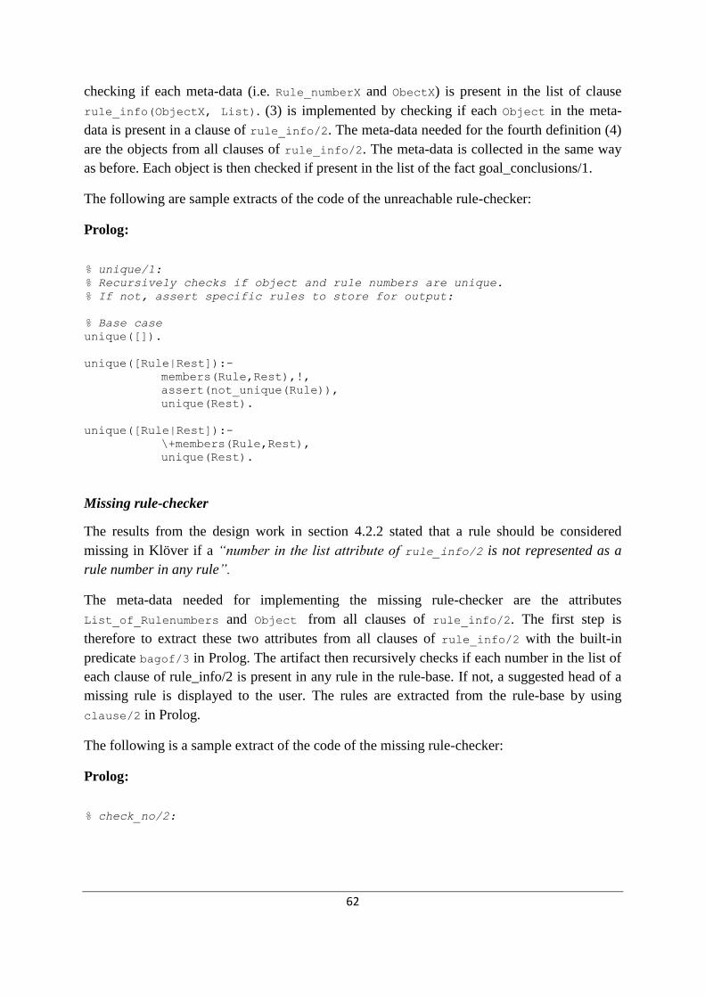
62
checking if each meta-data (i.e. Rule_numberX and ObectX) is present in the list of clause
rule_info(ObjectX, List). (3) is implemented by checking if each Object in the meta-
data is present in a clause of rule_info/2. The meta-data needed for the fourth definition (4)
are the objects from all clauses of rule_info/2. The meta-data is collected in the same way
as before. Each object is then checked if present in the list of the fact goal_conclusions/1.
The following are sample extracts of the code of the unreachable rule-checker:
Prolog:
% unique/1:
% Recursively checks if object and rule numbers are unique.
% If not, assert specific rules to store for output:
% Base case
unique([]).
unique([Rule|Rest]):-
members(Rule,Rest),!,
assert(not_unique(Rule)),
unique(Rest).
unique([Rule|Rest]):-
\+members(Rule,Rest),
unique(Rest).
Missing rule-checker
The results from the design work in section 4.2.2 stated that a rule should be considered
missing in Klöver if a “number in the list attribute of rule_info/2 is not represented as a
rule number in any rule”.
The meta-data needed for implementing the missing rule-checker are the attributes
List_of_Rulenumbers and Object from all clauses of rule_info/2. The first step is
therefore to extract these two attributes from all clauses of rule_info/2 with the built-in
predicate bagof/3 in Prolog. The artifact then recursively checks if each number in the list of
each clause of rule_info/2 is present in any rule in the rule-base. If not, a suggested head of a
missing rule is displayed to the user. The rules are extracted from the rule-base by using
clause/2 in Prolog.
The following is a sample extract of the code of the missing rule-checker:
Prolog:
% check_no/2:

63
% Recursively checks each number in list of rule_info/2 if a corresponding
% rule exists (with that Object and Number), if not – store as a missing
% rule.
% Base case
check_no(_,[]).
% Case1: A rule with specific Object and rule number already exists
check_no(Object,[No|Rest]):-
clause(rule(No,Object,_,_),_),
check_no(Object,Rest).
% Case2: A rule with specific Object and rule number is missing
check_no(Object,[No|Rest]):-
\+ clause(rule(No,Object,_,CF),_),
assert(missing_rules(Object,No)),
check_no(Object,Rest).
Figure 4.4 show an example of the artifact´s output after verification of completeness.

64
Figure 4.4: Screenshot of output of detected inconsistencies affecting the completeness
4.4 Prototype of the Artifact
According to Gregor and Jones (2007), an expository instantiation of the artifact is motivated
to represent the theory and illustrate how the system functions. The preceding sections of this
chapter have focused on presenting the implemented functionality of the artifact. In this
section, the focus will be on revealing how the user may interact and navigate through the

65
system, the usability of the artifact, and provide insight about the integration of the artifact
into Klöver. This will be done with the help of screenshots from an execution of the prototype
of the artifact.
At the initialization of Klöver, the user is provided with several options in the main menu,
shown in figure 4.5. A new option has been added: ―Verify rule base‖, which, when chosen,
initializes the verification of the rule-base, i.e. the artifact.
Figure 4.5: Screenshot of the main menu of klöver in SICStus
When the artifact has been initialized from the main menu, the user is provided with a menu
of options regarding the verification, as shown in figure 4.6.
Figure 4.6: Screenshot of the verification menu of Klöver in SICStus
If the user chooses one of the three first options (―Redundancy‖, ―Subsumed‖,
―Completeness‖), the artifact starts verifying the rule-base regarding these inconsistencies.
Expository instantiations of these three options have previously been presented in this chapter.
The option ―Back‖ navigates the user back to the main menu of Klöver.

66
The option ―Help‖ directs the user to a help menu (figure 4.7) where the user can find
information regarding the artifact and the different types of inconsistencies.
Figure 4.7: Screenshot of the help menu
The last option ‖Quit help‖ directs the user back to the verification menu (figure 4.6). When
one of the three options ―Redundancy‖, ―Subsumed‖ or ―Completeness‖ is chosen, the user is
provided with information regarding this inconsistency in Klöver, exemplified in figure 4.8.
Figure 4.8: Screenshot of the output information regarding redundancy
The user has then two options; get further information regarding the chosen type of
inconsistency in Klöver, or go back to the help menu. If the user chooses the first option,
examples of the appearances of the inconsistencies in Klöver is shown (figure 4.9).
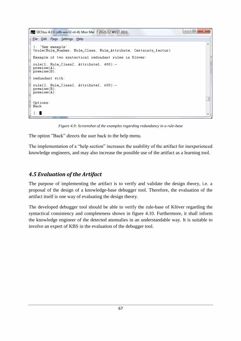
67
Figure 4.9: Screenshot of the examples regarding redundancy in a rule-base
The option ‖Back‖ directs the user back to the help menu.
The implementation of a ―help section‖ increases the usability of the artifact for inexperienced
knowledge engineers, and may also increase the possible use of the artifact as a learning tool.
4.5 Evaluation of the Artifact
The purpose of implementing the artifact is to verify and validate the design theory, i.e. a
proposal of the design of a knowledge-base debugger tool. Therefore, the evaluation of the
artifact itself is one way of evaluating the design theory.
The developed debugger tool should be able to verify the rule-base of Klöver regarding the
syntactical consistency and completeness shown in figure 4.10. Furthermore, it shall inform
the knowledge engineer of the detected anomalies in an understandable way. It is suitable to
involve an expert of KBS in the evaluation of the debugger tool.

68
The evaluation of the debugger tool was done in collaboration with the customer, who has
both the theoretical background and a vast experience from developing and using KBS. The
evaluation was conducted at two occasions in the end of the artifact´s development life-cycle.
At each occasion, the customer tested the prototype and then had the opportunity to provide
viewpoints and criticism in a subsequent discussion. Each occasion resulted in minor
refinements of the prototype which are summarized below.
Summary of customer´s first evaluation, September 3, 2011
The prototype was considered to fully realize the system requirements regarding the
functionality of the artifact. The prototype is able to detect all appearances of inconsistency
and incompleteness, which the artifact was implemented to identify.
The customer gave suggestions for improvements regarding the usability of the artifact;
mainly refinements of the text output to the user, but also about the user navigation through
the system. The customer also suggested an extension of the help section, by adding practical
examples of appearances of errors in the rule-base of Klöver.
Summary of customer´s second evaluation, September 23, 2011
The customer performed a code review before the second meeting. The feedback concerned
the documentation of the code. The customer gave a few suggestions for improvements
regarding the user interface. All suggestions were later realized into the final prototype.
Dead-end rules
Missing rules
Unreachable rules
Completeness
Figure 4.10: Implemented verification of consistency and completeness
Consistency
Redundant rules
Subsumed rules

69
5 Conclusions
Design science research should have both a practical contribution as well as contributing to
the knowledge-base according to Hevner et al (2004).
The proposed design theory in this thesis prescribes how a tool for automated verification of
rule-bases can be designed and developed. The successfully instantiated artifact is above all a
practical contribution, as it can verify a rule-base utilizing certainty factors of completeness
and consistency, by applying partly new and extended knowledge regarding this subject. The
positive results from the evaluation of the instantiation also give support to the theory.
The contribution to the knowledge-base comprises of constructs and methods which are
summarized below.
The theory prescribe a thorough analysis of the KBS to-be verified, early in the development
phase of the automated verification software. The purpose is to detect potential entities and
properties in the KBS that affect the completeness and consistency of the rule-base. For
example, errors in entities responsible for the order of the execution of rules may affect the
completeness in the rule-base. This analysis requires the developer of the verification tool to
possess deep knowledge about the implemented KBS. Alternatively, the developer needs to
involve and collaborate with the developers of the KBS during this analysis.
An iterative and incremental approach is also recommended for development of automated
verification software. Specific advices are to tolerate changes and updates of system
requirements during, and in-between, iterations. Furthermore, it was concluded beneficial to
start develop the most complex and error prone parts of the software.
One significant part of the design theory is the definitions of anomalies of consistency and
completeness relevant for KBS utilizing certainty factors (section 4.2). This work is based
upon, and extends, previous research regarding completeness and consistency in exact-
reasoning KBS (section 3.5). The combined theory regarding syntactical inconsistency and
incompleteness in both exact-reasoning KBS and KBS utilizing certainty factors are
summarized in table 5.1. Column 1 shows the general definitions of potential anomalies in
exact-reasoning KBS, as defined by previous research. Column 2 summarizes the potential
anomalies for general KBS utilizing certainty factors, proposed by the design theory. Column
3 summarizes the potential anomalies for the specific KBS Klöver, proposed by the design
theory.
Categories Column 1
Exact-reasoning rule-
based systems
Column 2
Inexact reasoning rule-
based systems utilizing
certainty factors
Column 3
Klöver

70
Redundant
rules
Identical conclusions and
premises
Identical conclusions and
premises
Identical conclusions and
premises
Conflicting
rules
Identical premises, and
conflicting conclusions
- -
Subsumed
rules
Identical conclusions, and
premises1 a subset of
premises2
- -
Subsumed
rules
- (Potential anomaly) Identical
conclusions, and premises1 a
subset of premises2 where
CFs > 0 and CF1 > CF2
(Potential anomaly)
Identical conclusions, and
premises1 a subset of premises2
where CFs > 0 and CF1 > CF2
Subsumed
rules
- (Potential anomaly) Identical
conclusions, and premises1 a
subset of premises2 where
CFs < 0 and CF1 < CF2
(Potential anomaly)
Identical conclusions, and
premises1 a subset of premises2
where CFs < 0 and CF1 < CF2
Circular rules A set of rules forms a cycle,
causing an infinite loop
A set of rules forms a cycle,
causing an infinite loop
A set of rules forms a cycle, does
not cause an infinite loop
Unnecessary
IF-conditions
Identical conclusions, and
contradicting premises
Identical conclusions, and
contradicting premises, and
CFs are identical
Identical conclusions, and
contradicting premises, and CFs
are identical
Dead-end
rules
A premise does not have an
input, or the input is illegal
(backward-chaining)
A premise does not have an
input, or the input is illegal
(backward-chaining)
A premise does not have an input,
or the input is illegal (backward-
chaining)
Missing rules Facts or question-values not
used within the rule-base
(Potential anomaly) Facts or
question-values not used
within the rule-base
-
Missing rules Dead-end goals Dead-end goals Dead-end goals
Missing rules - - A number in the list attribute of
rule_info/2 is not represented
as a rule number in any rule
Unreachable
rules
A conclusion is not a goal
of the system, and not a
condition of another rule
(backward-chaining)
A conclusion is not a goal of
the system, and not a
condition of another rule
(backward-chaining)
A conclusion is not a goal of the
system, and not a condition of
another rule (backward-chaining)
Unreachable
rules
- - Object and rule number of a rule
is not represented in a clause of rule_info/2
Unreachable
rules
- - Identical rule numbers and objects
Unreachable
rules
- - Object not represented in goal_conclusions/1
Table 5.9: Summary of errors affecting the completeness and consistency in rule-bases

71
Based on the results summarized in table 5.1, it can be concluded that potential anomalies
which may be an error, or may alternatively be intended, are possible in KBS utilizing
certainty factors. This demands the developer of a verification tool to make heuristic decisions
of when an anomaly should be considered an error. Furthermore, the results show that certain
anomalies in exact-reasoning KBS are actually legitimate in KBS utilizing certainty factors.
Moreover, as shown in Column 3, the analysis of Klöver resulted in the detection of several
anomalies specific for this system. A majority of these detected anomalies affected the
completeness of the rule-base. But in general, there are no differences between verification of
completeness in exact-reasoning and inexact-reasoning KBS utilizing certainty factors.
Furthermore, it can be concluded that the verification of consistency in Klöver does not differ
from the prescriptions for general KBS utilizing certainty factors. In summary, the results in
table 5.1 show the complexity of verification of completeness and consistency in KBS, and
that the appearances of anomalies in rule-bases are not always obvious.
As the proposed design theory is based upon existing theory about verification of
completeness and consistency, the result of this design science research is rather an
improvement of an already existing design theory.
Finally, the design theory is based on the framework by Gregor and Jones (2007), which was
introduced in section 2.1. The following section presents a final validation of the design
theory, checking if all components of the framework by Gregor and Jones (2007) are
represented in the proposed theory.
Purpose and Scope
Proposals of general requirements for automated verification tools for KBS was presented in
section 4.1
Constructs
Representations of entities in the proposed design of the verification tool are the elaborated
sub-categories of consistency and completeness, shown in figure 3.5. The definitions and
consequences of these entities vary, depending on the type of KBS the artifact debug, as
shown in section 4.2.2 and summarized in table 5.1.
Principle of Form and Function
Emphasis has been put on presenting and explaining the design product (i.e. the artifact) in
detail; functions, features and attributes of the artifact are presented in sections 4.3 and 4.4.
Domain knowledge needed to assimilate this information is provided in the theoretical
background (chapter 3).
Artifact Mutability

72
The artifact is limited to verify the completeness and consistency of rule-bases in the KBS-
shell Klöver. The verification tool can dynamically debug all implemented rule-bases in
Klöver.
Testable Propositions
Some of the propositions of the design theory can be formalized in the following testable
hypothesis:
To develop a consistent debugging tool of rule-bases, it is critical to perform a
preparatory analyze of the KBS to-be verified, to identify entities and inferencing
mechanisms affecting the appearances of inconsistencies and incompleteness.
An iterative and incremental development method is appropriate for developing KBS
debuggers by small teams.
By providing clear definitions and explanations of detected inconsistencies, the
verification tool can be used as a learning tool for knowledge representation.
Justificatory Knowledge
The proposed definitions of the sub-categories of consistency and completeness are based on
logic, and explained with the help of Prolog code examples, a programming language based
on first-order logic.
Principles of Implementation
The encouraging results from the evaluation of the artifact make it appropriate to propose an
iterative and incremental approach for developing these artifacts.
Implementation of the verification of redundant rules is recommended to precede the
implementation of the verification of subsumed rules, because of the possibility of reusing
capabilities of the redundancy check in the subsumed rule check.
Expository Instantiation
The implementation of the artifact is presented in detail in sections 4.4 and 4.5.

73
6 Discussion
The design theory has a focus on verification of inexact-reasoning KBS utilizing certainty
factors. This can be interpreted as a limitation of the applicability of the theory. However, the
certainty factor technique is the most applied inexact-reasoning method in KBS today
(Turban, 2011). One significant product of this research is the customization of completeness
and consistency theory for a specific class of KBS. A reflection made during this research is
that it is difficult to construct design theories applicable to general development of
verification tools for all classes of KBS. This is usually the case in the field of IS.
The encouraging results from the evaluation of the artifact strengthen the proposal of an
iterative and incremental development approach. However, other development methods could
of course be proven to be equally suitable. Furthermore, the verification tool was developed
by a single person. Therefore, the suitability of an IID approach for mid- and large sized
projects still needs to be verified.
Part of this design science research is the actual verification tool software developed and
integrated into the specific KBS shell Klöver. As explained before, the main benefit of this
software is to automate the process of verifying rule-bases of completeness and consistency,
which saves time for the rule developer and ensure a certain level of quality of the rule-base.
However, there might be other benefits to reap with these artifacts. Verification tools that
output detailed and understandable explanations to the rule developers about why the detected
rules are potentially incomplete and inconsistent, might as an side-effect act as a learning tool.
The construction of a design theory for automated verification of rule-bases, and the detailed
presentation of its instantiation will hopefully contribute and enrich the knowledge-domain of
this topic. Retrospectively, this design science research revealed processes, considerations and
decisions involved in the development of automated verification tools for rule-bases. In
summary, this research has visualized some of the complexity involved in verification of
completeness and consistency in rule-bases.
6.1 Future Work
To further test and evaluate the proposed design theory, future work could expand the
instantiation of the theory, verifying a rule-base of the remaining categories of completeness
and consistency. Further work is also needed to look into the design of automated verification
of semantic consistency and completeness.

74
Another suggestion is to investigate if existing design theory about automated verification of
completeness and consistency applies for business rules and rule engines. There is arguably
great potential benefits of such software in that context, as modern business organizations in
dynamic and competitive environments are increasingly complex, and exposed to frequent
change. Consequently, business rules need to frequently be updated, added or deleted. This
put demands on the consistency and completeness of the business rules.
Another suggestion for future work is to study the actual interaction between rule developers
and automated verification tools. For example, it could be interesting to investigate whether or
not these artifacts are beneficial for developments of fairly small rule-bases, where manual
verification is less cumbersome and error-prone. It is also essential to investigate what
experiences rule developers actually get from using automated verification tools.

75
References
Abraham, A. (2005). Rule-based expert systems- Handbook of Measuring System Design,
John Wiley & Sons, N.J, pp. 909-919.
Adrion, W.R., M.A. Branstad and J.C Cherniavsky (1982). Validation, verification and testing
of computer software. ACM Computing Surveys (US), 14, 2, pp. 159-192.
Aniba, M.R., S. Siguenza, A. Friedrich, F. Plewniak, O. Poch, A. Marchler-Bauer and J.D.
Thompson. (2008). Knowledge-based expert systems and a proof-of-concept case study
for multiple sequence alignment construction and analysis. Briefings in bioinformatics,
(10)1, pp. 11-23.
Awad, E. M. & H. M. Ghaziri (2003). Knowledge management. (1. ed.) Upper Saddle River,
N.J.: Prentice Hall.
Bahill, A.T. (1991). Verifying and validating personal computer-based expert systems.
Englewood Cliffs, N.J: Prentice Hall
Boehm, B. (1984). Verifying and validating software requirements and design specifications.
IEEE Software, Vol. 1(1).
Boole, G. (2003). [1854] An investigation of the laws of thought. Amherst, NY: Prometheus
Books.
Bratko, I. (2001). PROLOG – programming for artificial intelligence. (3. Ed) Harlow:
Addison-Wesley.
Buchanan, B. G. & R. O. Duda. (1982). Principles of rule-based expert systems,.Advances in
Computers, Vol. 22.
Buchanan, B. G. & E. H. Shortliffe (1984). Rule-based expert systems – the MYCIN
experiments of the Stanford heuristic programming project. Addison-Weasley
Publishing Company.
Byrd, T. A. (1995). Expert systems implementation: interviews with knowledge engineers.
Industrial Management and Data Systems, Vol. 95, No. 10, pp. 67-75.
Coverity press release (2008) Quality Problems Cost Software Companies Up to $22 Million
Annually According to New Report. [Online] Avaliable at:
http://www.coverity.com/html/press_story65_08_04_08.html. [Accessed 15 November
2011].
Codd, E. F. (1970). A relational model of data for large shared data banks. Communications

76
of the ACM, (13)6, pp. 377-387.
Codd, E. F. (1982). Relational database: a practical foundation for productivity (The 1981
Turing Award Lecture). Communications of the ACM, (2)25, pp. 109-117.
Cragunt, B. J.& H. J. Steudel (1986). A decision-table-based processor for checking
completeness and consistency in rule-based expert systems. Int. J. Man-Machine
Studies. (1987) 26, pp. 633-648.
Durkin, J., (1994). Expert systems – design and development. Macmillan Publishing Co, NJ,
Prentice-Hall.
Edman, A. & L. Sundling (1993). An educational knowledge-based expert system for
environment protection. In Proceedings of Sixth International PEG Conference, pp.
124-128. Rapallo, Italy.
Edman, A., A. Håkansson, and L. Sundling (2000). A consultative system for investments,
Klöver. Department of Information Science, Uppsala University, Sweden.
Edman, A. (2001). Combining knowledge systems and hypermedia for user co-operation and
learning. Ph.D. Thesis, Uppsala University, Sweden.
Galliers, R.D. (1991). Choosing appropriate information systems research approaches: a
revised taxonomy. Information System Research: Contemporary Approaches and
Emergent Traditions, Elsevier Science Publishers B.V., North-Holland.
Gomolka, Z., & C. Orlowski (2000). Knowledge management in creating hybrid systems for
environmental protection. Cybernetics and Systems: An International Journal, 31, pp.
507-529.
Gonzalez, A.J. & D.D. Dankel. (1993). The engineering of knowledge-based systems – theory
and practice. Englewood Cliffs, N.J.: Prentice-Hall.
Gregg, D., U. Kulkarni, & A. Vinze. (2001). Understanding the philosophical underpinnings
of software engineering research in information systems. Information Systems
Frontiers, (2)3, pp. 169-183.
Hayes-Roth, F., D. Waterman and D. Lenat (1984). Building expert systems. Addison-Wesley,
MA, United States.
Hevner, A. & S. March. (2003). The information systems research cycle. IEEE Computer,
(36)11, pp. 111-113.
Håkansson A. & C. Öijer (1993). Developing an expert system for analyzing environmental
consequences. Thesis for the degree of Bachelor of Science, Majoring in Computer
Science, Uppsala University, Sweden.
77
Håkansson, A., A. Widmark, A. Edman (2000). The KANAL-system, an intelligent rule
editor supporting the knowledge acquisition process. Proceedings of Swedish AI Society
Workshop, SAIS-00. Linköping, Sweden.
Iversen, J., L. Mathiassen, and P. Nielsen (2004). Managing process risk in software process
improvement: an action research approach. MIS Quarterly, (28)3, pp. 395-434.
Jeppesen, S. & A. Lundén (2005). Sune – ett beslutstödsystem för lärare om
narkotikamissbruk. Thesis for the degree of Master of Science, Majoring in Computer
Science, Uppsala University, Sweden.
Johansson, A., A. Eriksson-Granskog, and A. Edman (1989). Prolog versus you. (2 ed.) Lund:
Studentlitteratur.
Laudon, K. C., & J. P. Laudon (2002). Essential of management information systems. (5. ed.)
Englewood cliffs, NJ: Prentice Hall.
Leung, K. S., & W. Lam (1988). Fuzzy concepts in expert systems. Computer, (21)9, pp. 43-
56.
Liao, S.H. (2005). Expert system methodologies and applications—a decade review from
1995 to 2004. Expert Systems with Applications 28, pp. 93–103.
Liebowitz, J, (1994). Expert systems: a short introduction. Engineering Fracture Mechanics,
(50) 5/6, pp. 601-607.
Liebowitz, J. (1997). Knowledge-based/expert systems technology in life support systems.
Kybernetes, (26)5, pp. 55-73.
Mahmoud, Q, H. (2005). Java rule engine API (JSR 94): toward rule-based applications.
[Online]. Available at:
http://java.sun.com/developer/technicalArticles/J2SE/JavaRule.html
[Accessed 28 May 2011].
March, S.T., and V.C. Storey (2008). ―Editorial,‖ MIS Quarterly: Special Issue on Design
Science Research, September.
March, S. T., and Smith, G (1995). ―Design and Natural Science Research on Information
Technology,‖ Decision Support Systems (15:4), pp. 251-266.
Metaxiotis, K., & J.E. Samouilidis (2000). Expert systems in medicine: academic illusion or
real power? Information Management and Computer Security, (8)2, pp. 75-9.
Metaxiotis, K., D. Askounis, J. Psarras (2001). Expert systems in production planning and
scheduling; a state-of-the-art survey. Journal of Intelligent Manufacturing.

78
Metaxiotis, K. & J. Psarras. (2003). Expert systems in business: applications and future
directions for the operations researcher. Industrial Management & Data Systems,
(103)5, pp. 361-368.
Mockler, R.J., D.G. Dologite and M.E. Gartenfeld (2000). Talk with the experts: learning
management decision-making using CAI. Cybernetics and Systems: An International
Journal, 31, pp. 431-464.
Nguyen, T., W. Perkins, T. Laffey, and D. Pecora (1987). Knowledge base verification. AI
Magazine, (8)2, pp. 69-75.
O’Keefe, R., 0. Balci and E. Smith (1987). Validating expert system performance. IEEE
Expert, (2)4, pp. 81-89.
O´Keefe, R., & D. E. O´Leary (1993). Expert system verification and validation: a survey and
tutorial. Artificial Intelligence Review. Vol. 7, pp. 3-42.
O´Leary, T.J., M. Goul., E. Kathleen, E. Moffitt, and A.E. Radwan (1990). Validating expert
systems. IEEE Expert: Intelligent Systems and Their Applications , (5)3, pp. 51 – 58.
Pfleeger, S.L. (2001). Software engineering: theory and practice. (2nd
ed) Upper Saddle
River: Prentice Hall.
Preece, A. (1993). A new approach to detecting missing knowledge in expert system rule
bases. Int. J. Man-Machine Studies, 38, pp. 661-688.
Preece, A. (2000). Evaluating verification and validation methods in knowledge engineering.
Springer-Verlag, pp. 91-104.
Sen, M.D.L., J.J. Minambres, A.J. Garrido, A. Almansa and J.C. Soto (2004). Basic
theoretical results for expert systems, application to the supervision of adaption
transients in planar robots. Artificial intelligence, 152, pp. 173-211.
SICStus Prolog [Online] Avaliable at: http://www.sics.se/isl/sicstuswww/site/index.html
[Accessed 10 October 2011].
Shortcliffe, E.H., A.C. Scott, M.B. Buschoff, A.B. Campbell, W.V. Melle amd C.D. Jacobs
(1981). ONCOCIN: an expert system for Oncology protocol management. In Proc 7th
IJCAI Conference, Vancouver: IEEE, pp. 876-881.
Sommerville, I (2007). Software engineering. (8. ed.) Harlow: Addison-Wesley.
Spencer, L. & A. Dale (1979). Integration and regulation in organizations: a contextual
approach. Sociological Review, 27(4), pp. 679-702.
Stachowitz, R.A., J.B. Combs and C.L. Chang (1987). Validation of knowledge-based

79
systems. In Second AIAA/NASA/USAF Symposium on Automation, Robotics and
Advanced Computing for the National Space Program. New York: American Institute
of Aeronautics and Astronautics, pp. 1-9.
Suwa, M., A. C. Scott, and E.H. Shortliffe (1982). Completeness and consistency in a rule-
based system. The AI Magazine , (3), pp. 16-21.
Reigeluth, C. M. (red.) (1999). Instructional-design theories and models: a new paradigm of
instructional theory. [Ny utg.] Mahwah, N.J.: Lawrence Erlbaum
Turban, E. & J. E. Aronson (2001). Decision support systems and intelligent systems. (6th
ed). Hong Kong: Prentice International Hall.
Turban, E., J. E. Aronson, T. P. Liang and R. Sharda (2007). Decision support and business
intelligence systems. (8th ed.). N.J: Prentice International Hall, USA.
Turban, E., R. Sharda and D. Delen (2011). Decision support and business intelligence
systems. (9th ed.). N.J: Prentice International Hall, USA.
Waterman, D. (1986). A guide to expert systems. Addison-Weasley Pub, MA, United States.
Watson, H. J. (2009). Tutorial: Business intelligence – past, present, and future.
Communications of the Association for Information Systems, 25(39), pp. 487-510.
Wong, B.K., J.K.S Chong and J. Park (1994). Utilization and benefits of expert systems in
manufacturing : a study of large American industrial corporations. International Journal
of Operations & Production Management, (14)1, pp. 38-49.
Wright, G. & G. Rowe (1992). Expert systems in marketing: current trends and an alternative
scenario. Marketing Intelligence & Planning, (10)6.
Xirogiannis, G., J. Stefanou, B. Fu, S. Xiao and C. Peng (2004). The internet-based
knowledge acquisition and management method to construct large-scale distributed
medical expert system. Computer Methods and Programs in Biomedicine, 74, pp. 1-10.
Zadeh, L.A. (1965). Fuzzy Sets. Information and Control, 8, 338–353.
Ågerfalk, P.J. and B. Fitzgerald (2006). Exploring the concept of method rationale: a
conceptual tool to understand method tailoring. Advanced Topics in Database Research.
Volume 5, pp. 63-76.

80
Appendices
Appendix 1: Manual of Klöver
Authors: Anneli Edman, Lena Sundling and Anne Håkansson
The purpose of Klöver
Klöver have been carried out as an assignment for a course ―Knowledge-based system in
Prolog‖. The main purpose has been to give students experience in how to create a
knowledge-based system from the start to a functioning program in the programming
language Prolog. The proposal of the domain was investment advice on the basis of written
material.
Klöver asks a person about factors related to both his private financial situation as well as
national economic factors. Based on these issues Klöver then gives a recommendation on how
the person should invest the money. The system has rudimentary knowledge of gold,
diamonds, stocks, index options, bonds, tax-deductible savings accounts and art.

81
User manual
The development system SICStus Prolog is used to run the knowledge-based system Klöver.
When the system has loaded the file, it is clear to start. This is done by writing expert.
(Followed by a point.)
? - expert.
What happens then is that these options are presented:
Consult
Starts a new consultation with Klöver.
Consult with given answers
Start a consultation where Klöver has kept the already given answers from the previous
session, and will therefore only ask questions that were previously not answered.
Save answers
Saves all the answers given to a file that you can name.
Save Session
Saves all the answers (the predicate answer / 2) given to a file with the conclusions (trigged /
3) and information on rules that succeeded and failed (how / 4).
Fetch old answers
Loading responses saved on a file to Klöver and lists them. In connection with the upload
Klöver will ask if the predicate answer / 2 should be redefined. If the answer is yes type: y.
Fetch old session
Loading the saved response and achieved results to Klöver, and lists the information.
Confirm that the predicates how / 4, answer / 2 and trigged / 3 will be redefined.
List database
Lists the predicates answer, trigged and how.
Quit
Ends Klöver completely and allows you to return to Prolog.
When you do a consultation with Klöver, you will have to answer questions of different types.
If you want to know why a question is asked, print Why to get a text explanation. Then
answer the question.
When Klöver has asked all relevant questions the program will present the results. After that
you can choose between the following actions:
New Session
Klöver starts a new consultation and the old answers are cleared.

82
Change answers
Possibility to change the answers. If you don´t change your answers the previous given values
remains.
How explanation
Provides explanations of how Klöver came to the conclusions. You can choose the conclusion
you want have explained from a menu.
Interrupt
Terminates the session completely and goes up to the top level of Klöver.
In addition, Consult with given answers, Save answers, Save session, Fetch old answers,
Fetch old session, and List database (which are all defined above) can be elected.

83
The architecture of the system
Klöver has the following components (Figure 1):
- The Knowledge Base (KB) consists of rules, information on rules and information related to
the conclusions.
- Query base containing all the system's issues and information that is linked to these.
- The interpreter will draw conclusions based on rules, dealing with uncertainty management
and presentation of results. The interpreter also adds up the menu bar.
- The query generator handles the initial questioning.
- The explanation mechanism handles How-explanations and Why-definitions.
Figure 1: Illustration of how the different parts in the system collaborate.
a) Questions generated by the query generator.
b) Questions generated by the interpreter from rules.
c) Any supplementary questions to the issues in b.
d) Reading and storage of the responses.
e) Interpretation of the rules.
f) Reading and storage of the responses.
g) Reading of rules for explanations.
h) Reading of information on how the rules were used.

84
Representations in the knowledge database
Rules
Klöver is a rule-based system. The rules generally have the following form:
rule(Number,Object, Attribute, Certaintyfactor):-
condition1,
condition2,
...
condition_n.
The certainty factor may have a value between -1000 and 1000. The conditions are connected
with and (,), or (;) and negation (\ +). The conditional clauses can be arbitrary Prolog clauses
or of the type check. Conditions of the latter kind will be interpreted by the system´s inference
mechanism. The predicate check can look as follows:
For objects given by the questions:
check(Object, Conditions, Attribute)
Where conditions can be one of the following; =, >, >=, <, =<, '<>'.
check(Object, Number, Attributelist)
Checks that Object is equal to the minimum number of attributes of the attribute list.
For objects determined by the rules:
check(Object, Attribute, Conditions, Value)
Where conditions may be one of the following; 'cf>=', 'cf<', 'value>=', 'value<', 'value='
and cf means certainty factor.
check(Object, Attribute, Truth_value)
Where the Truth_value is either true or false.
check(Object, Number, outof, Attributelist)
Checks that Object is equal to the minimum Number of attributes of the Attributelist. Only the
attributes set with a certainty factor of 1000 (true) will be considered.

85
Information on objects determined by rules
All conclusions will be declared together with the rules. The rules can set the conclusions as
follows: List_of_rulenumbers gives the rules that can deduce the conclusion Object.
rule_info(Object, List_of_rulenumbers).
The system's all goal parameters are added in a list of goal parameters as follows:
goal_conclusions(List_of_goalparameters)
The objects to be presented in the system's presentation of the results are declared as follows:
to_present(List_of_objects).
The text to be attached to the objects at the presentation of the results are stored as follows:
text(Object, 'String').
Representation of questions
All questions are declared as follows:
question_info(Object, 'Question', List_of_alternatives, Type, Condition)
The type can be:
w = fill in question, arbitrary response
s = single choice question
m = multi-choice question
The conditions may have the following forms:
Empty list - no conditions
or (Simple condition1, Simple condition2) - disjunction, one or the other or both.
and - a list of simple conditions
not (simple condition) - negated conditions
simple condition – only one simple condition
Simple conditions are written on the form:
Objects (Attributes) - true if the user answered Attributes to the question concerning the
Object or
(Object Value Terms)
where conditions are the following:>, <,> =, = <, =

86
Information on objects determined by questions
The order in which the initial questions are to be examined is in the query sequence:
question_order(List_of_objects).
Some questions are generated from the knowledge base through the interpreter. It is possible
to declare follow-up questions to those questions and they will be asked in direct connection.
This is done like this:
question_sequence(Object, List_of_objects_that_are_follow-up_questions).

87
The question generator
All questions in Klöver are declared as question_info clauses, but they are used differently.
Whether a question shall be asked is determined by the past given answers and the conditions
connected to the question.
The questions not included in the initial query session may be generated from the inference
mechanism. These questions may also have follow-up questions declared to be asked in direct
connection. Follow-up questions exist in a list which is fed into the dialogue generator and
subjected to the same procedure as the initial questions, i.e. with conditions. In this way, there
is an opportunity to address the complete area of questions when one question is generated
from the inference mechanism.
Since all the questions in principle, can be asked either from the question generator or from
the inference mechanism, it is difficult to know whether the findings are a result generated
from the questions or the inference mechanism. Therefore all findings are always reviewed
when the user changes the answer.
A possible extension of the query strategy would be to be able to control the order of the
questions generated from inference machine also. This could be implemented simply by doing
the following:
1. Examine initial questions
2. Examine all goal parameters and every time a condition that is an unanswered question is
found, store this question in a ‖need-to-know-set‖.
3. When all rules are examined the "need-to-know-set" is sorted in accordance with the
regulations for the order of the questions and can be stored together with the initial (other,
ordinary) questions.
4. The questions in the "need-to-know-set" are asked in arranged order.
5. Repeat 2-4 until no more questions need to be asked.
This solution means that rules might have to be reviewed several times but controls of simple
conditions do not require significant resources. It would not be as ineffective as it might seem.
Moreover, no information on the conclusions or explaining information is saved until a rule is
completely ready.

88
Representation in the database
There are three different types of clauses in the system's dynamic database, user-specified
response, drawn conclusions and information used for the systems how-explanations. These
are represented as follows:
Answer: answer(Object1,Attribute1).
answer(Object2,Attribute2).
......
answer (Objectn, Attributn).
Where n>= 0
Eg: answer(capital,100000).
answer(interest,stock).
answer(interest,art).
Drawn conclusions:
trigged(Object, Attribute, Certaintyfactor)
Eg: trigged(object_of_investment, stock, 500)
Explanatory Information:
how(Rulenumber1, Object1, Attribute, Value1)
how(Rulenumber2, Object2, Attribute, Value2)
.....
how(Rulenumber, Objectnumber, Attribute, Value_n)
Where n>= 1
Eg: how(70, object_of_investment, shares, 500).
If the rule fails the explanatory information is saved as follows:
how(Rulenumber, Object, Attribute, rejected).
Eg: how(10, object_of_investment, gold, rejected).

89
The inference mechanism
The inference mechanism is a traditional, backward chaining depth-first interpreter. All
parameters declared as goal parameters, i.e. goal_conclusions, in the system will be examined
in the order they are declared. The goal parameters are normally set by the rules, which in its
part have conditions. These conditions will then be the system's new targets to explore, etc.
The parameters are examined in two steps, first the system tries to find the value of the
parameter and then decide whether the conditions set are valid.
In order to find a value for a parameter there are several methods. These are examined in the
following order:
- If it is a user-given response.
- If it is a drawn conclusion.
- If it is an unanswered question, the question itself and any follow-up questions will be asked
and the answers stored.
- If there are rules for the object they will be examined and the conclusion will be stored.
When the parameter is set to a value in any of these steps, the condition is examined. All goal
parameters are unconditional, that is they always succeed if they are set to a value.
Searching the rules for an object is based on lists of rules that will set every object. Each rule
is examined and if its condition goes through the inference mechanism the conclusion is
drawn in the head of the rule. Because the system is working with an uncertainty management
á la Mycin the certainty factor has to be updated for each rule that goes through. This is done
and the clause that is being stored will have the new updated certainty factor as its value.

90
Explanations
Klöver has simple why-explanations. In connection to a question being asked, you can choose
to have an explanation to why the question is asked using Why. The explanation is given in
the form of a text.
Klöver offers how-explanations after a session. These are implemented relatively simple and
are based on the assumption that the rules of the system can serve as explanations. All the
information on the drawn conclusions is stored in the database. When the user is presented
with the result of the system's performance, he or she can choose How. A list of all objects,
on which the system has been able to draw any conclusions upon, will be displayed. The user
can choose what conclusion to be explained. The explanation consists of the rules and the
information about if the premises are given by the user or drawn as a conclusion. Equal to the
why-explanations this process can continue with new conclusions until the user is satisfied.

91
Presentations
The system presents its results to the user in a text window. Which response that is presented
is governed by the parameters declared as presentation parameters in the knowledge-base.
For each presentation parameter a text string is stored that can be used during the presentation
of the parameter.
After a session, you can see the certainty factors that the system reached via List database.
After the results are displayed the certainty factors are translated to text as follows:
Very probable if CF> = 700
Probable if 400 = <CF <700
Can not be excluded if 0 = <CF <400
Not recomended for CF <0
This classification is defined in the predicate evaluation can easily be reprogrammed. The
presentation of the results is pretty rudimentary but we consider it sufficient for the
application. There is also no problem to extend it and make it more sophisticated.

92
Appendix 2: Prolog Tutorial
Educational material written by Anneli Edman. Adapted from Johansson et al (1989).
Prolog, PROgramming in LOGic, is an example of a logic programming system.
Some of Prolog’s fields of applications:
- Natural language processing
- Databases
- Expert systems & knowledge-based systems
- Planning
- Construction of compilators
- CAD (Computer Aided Design)
Prolog is a general programming language with a mechanism that can draw logical
conclusions from the statements in a Prolog program.
A Prolog program consists of Horn clauses. The Horn clauses are a subset of the predicate
calculus, a form of logic. A Horn clause can have the following formats:
in logic x1...xn (AB1 … Bi)
in Prolog A B1, B2 ,… , Bi written as A:- B1, B2 ,..., Bi (i)
A written as A. (ii)
A written as ?- A. (iii)
In (i) the relation A is true if all the relations B1 up to Bi are true. This means that the
conclusion A is true if the conditions B1 and B2 and … and Bi are satisfied. (ii) Means that
the relation A is always true. (iii) Is the form for a question to the system whether the relation
A is true. The answer is yes if A can be fulfilled and if not the answer is no.
The Horn clauses will also be called clauses.
Prolog is a declarative programming language. This means that we declare what is valid for a
world, i.e., what is true in our world. Most of the programming languages are imperative,
which means that we define what should be performed when a condition is fulfilled. In Prolog
we investigate what is true and false and we are not focused on a sequence of actions.

93
Introduction to Prolog
Let us start with an ancient legendary world, that of Norse mythology.
Facts
We would like to describe that Thor is an as, which is a Norse god.
Note: The clauses end with a full stop ".".
The number of arguments decides the arity of the predicate. The predicate or relation as has
arity 1.
Balder is also an as.
Our Prolog program should be extended with the fact that Freya is a van.
as('Thor'). (1)
as('Balder'). (2)
van('Freya'). (3)
When a variable gets a value, e.g., when X gets the value Thor, you say that the variable gets
instantiated.
as('Thor'). clause
predicate name
argument
as('Thor').
as('Balder').
relation
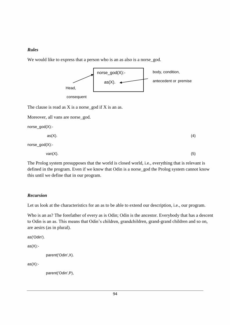
94
Rules
We would like to express that a person who is an as also is a norse_god.
The clause is read as X is a norse_god if X is an as.
Moreover, all vans are norse_god.
norse_god(X):-
as(X). (4)
norse_god(X):-
van(X). (5)
The Prolog system presupposes that the world is closed world, i.e., everything that is relevant is
defined in the program. Even if we know that Odin is a norse_god the Prolog system cannot know
this until we define that in our program.
Recursion
Let us look at the characteristics for an as to be able to extend our description, i.e., our program.
Who is an as? The forefather of every as is Odin; Odin is the ancestor. Everybody that has a descent
to Odin is an as. This means that Odin’s children, grandchildren, grand-grand children and so on,
are aesirs (as in plural).
as('Odin').
as(X):-
parent('Odin',X).
as(X):-
parent('Odin',P),
norse_god(X):-
as(X).
body, condition,
antecedent or premise
Head,
consequent

95
parent(P,X).
as(X):-
parent('Odin',P1),
parent(P1,P2),
parent(P2,X).
and so on.
Since we don’t know how many generations we need to define the relation as for we need to define
the relation in a more general form – and also in a more effective way. What we describe above is
that someone is an as if the parent is an as. This can be described in the following way:
as('Odin'). (6)
as(X):-
parent(P,X),
as(P). (7)
(6) Describes that Odin is an as. (7) Expresses that X is an as if P is a parent to X and if P is also an
as. (7) Is a recursive definition since we use the definition for as to define what is true for as. In
recursive definitions there has to be at least one base case, in this case (6) is our base case, to
prohibit an infinite evaluation of the predicate.
To be able to use the predicate as as it is defined in (6) and (7) we need to define the relation parent.
A person is a parent to a child if the person is the mother or the father to the child.
parent(P,C):-
mother(P,C). (8)
parent(P,C):-
father(P,C). (9)
(8) can be read as P is a parent to C if P is a mother to C.
as('Odin').
as(X):-
parent(P,X),
as(P).
base case
recursive case

96
father('Odin','Thor'). (10)
father('Thor','Trud'). (11)
father('Thor','Magne'). (12)
The connective “and” and “or”
If you don’t want to use the definition of parent in the predicate as you can use the predicates
mother and father in the statement (7).
as('Odin'). (6)
as(X):-
mother(P,X),
as(P). (7a1)
as(X):-
father(P,X),
as(P). (7a2)
(7a1) and (7a2) can be put together in a clause if you use the connective for ―or‖,i.e., ―;‖.
as(X):-
(mother(P,X); father(P,X)),
as(P). (7b)
Since the connective ―and‖ binds harder than ‖or‖ you have to use parenthesis to get a right
definition. If you don’t use the parenthesis (7b) will be:
as(X):-
mother(P,X);
father(P,X),
as(P).
The interpretation of this statement is that if P is a mother to X then X is an as, alternatively X is an
as if P is the father till X and P is an as. This interpretation can also be described by the following
two clauses:

97
as(X):-
mother(P,X).
as(X):-
father(P,X),
as(P).
Prolog’s way of reasoning
Let us look at the following problem: How are animals behaving?
mammal(X):- (13)
viviparous(X),
carnivore(X).
viviparous(lion). (14)
viviparous(tiger). (15)
carnivore(Y):- (16)
has_sharp_teeth(Y),
has_claws(Y).
has_sharp_teeth(lion). (17)
has_sharp_teeth(tiger). (18)
has_claws(tiger). (19)
has_claws(lion). (20)
Prolog is searching for the answers
- upside and down (from question to answer)
- from left to right (in questions comprising several conditions)
- depth first (investigates a branch first)
The proof procedure from input to output

98
Different types of objects
Constants
• atoms
- starts with a lower case letter, e.g., anna, tiger, viviparous
- strings of special characters, e.g., <-->
- strings within ' ', e.g., 'Thor', 'Has sharp teeth'
• numbers, include integer and real numbers
1 121 3.13 -573
Variables
Starts with an upper-case letter or _ ,e.g., X, Father, Person, _t1, _4
data objects
simple objects structures
constants variables
atoms numbers
mammal(X)
yes/no
X = lion
question/goal
Program
succeed/fail
instantiation of
variables
Execution

99
Structures
Have the form functor(arg1, arg2, ..., argN)
e.g., date(2009,1,21), personal_number(850807,-,4567)
student( name(’Anna’, ’Johansson’) ,’IM’)
functor argument
Matching/unification
If a question could match a fact or a rule’s head they have to be able to be unified. The rules for the
unification are:
• Two predicates can be unified if
- they have the same predicate name
- they have the same arity (equal number of arguments)
- the arguments can be unified
• Two terms can be unified if either
- one is an variable
- both are the same constants
- both are structures and
- they have the same functor
- they have the same arity
- the arguments can be unified