verisurf x – verisurf tools · pdf fileverisurf tools are specific tools developed by...
TRANSCRIPT
Verisurf Software, Inc.
Verisurf X – Verisurf Tools

Verisurf X Tools User Manual
Preface
This Reference Manual contains information protected by copyright and subject to change without notice. No part of this Manual may be reproduced in any form without prior and written consent from Verisurf Software, Inc.
Verisurf Software, Inc. shall not be responsible for technical or editorial errors or omissions. Product names are trademarks or registered trademarks of their respective companies.
The software described herein is furnished under license and non-disclosure agreement, and may be used only in accordance with the terms of the sales agreement.
© Verisurf Software All rights reserved
Manual release July, 2013
Contact
Verisurf Software, Inc.
4907 E. Landon Drive
Anaheim, CA 92807
Phone 714-970-1683
Fax 714-701-0280
www.verisurf.com
Feedback
Your feedback is important as we strive to improve the quality of our documentation. Please use the following E-Mail address to send in suggestions:

Ver isur f X6.1/X7 Table of Con tents | 1
Contents Verisurf Tools Overview..................................................................................................................................................... 1
Using Verisurf Tools .......................................................................................................................................................... 3 Screenshot ..................................................................................................................................................................... 4 HiddenLine ..................................................................................................................................................................... 4 Notepad ......................................................................................................................................................................... 4 Calculator....................................................................................................................................................................... 4 Verisurf Hole Axis .......................................................................................................................................................... 5 Auto Hole Axis ............................................................................................................................................................... 6 Minimum Bounding Box ................................................................................................................................................ 7 Verisurf Pierce ............................................................................................................................................................... 9
Verisurf Pierce Dialog ................................................................................................................................................. 9 Extend Lines ................................................................................................................................................................. 10 PowerSelect ................................................................................................................................................................. 11 Auto Flip Normals ........................................................................................................................................................ 12 Name Points ................................................................................................................................................................ 14 Fit Curve from Chain .................................................................................................................................................... 15 Verisurf Planes ............................................................................................................................................................. 17 Verisurf WCS ................................................................................................................................................................ 18 Add a Capture View ..................................................................................................................................................... 19

Ver isur f X6.1/X7 Ver isur f Tools | 1
Ver isur f X6.1/X7 Ver isur f Tools | 1
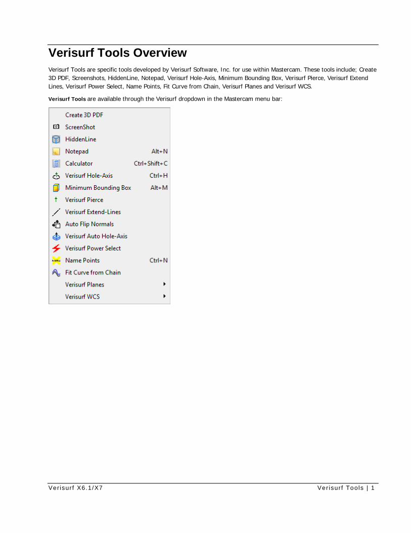
Verisurf Tools Overview Verisurf Tools are specific tools developed by Verisurf Software, Inc. for use within Mastercam. These tools include; Create 3D PDF, Screenshots, HiddenLine, Notepad, Verisurf Hole-Axis, Minimum Bounding Box, Verisurf Pierce, Verisurf Extend Lines, Verisurf Power Select, Name Points, Fit Curve from Chain, Verisurf Planes and Verisurf WCS.
Verisurf Tools are available through the Verisurf dropdown in the Mastercam menu bar:

Ver isur f X6.1/X7 Ver isur f Tools | 3
Using Verisurf Tools The following paragraphs will outline the use of the Verisurf Tools Menu functions:
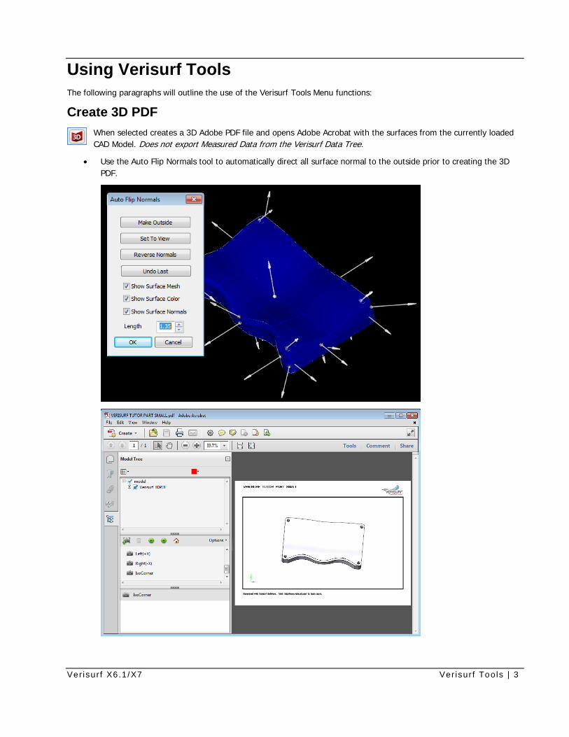
Create 3D PDF When selected creates a 3D Adobe PDF file and opens Adobe Acrobat with the surfaces from the currently loaded CAD Model. Does not export Measured Data from the Verisurf Data Tree.
• Use the Auto Flip Normals tool to automatically direct all surface normal to the outside prior to creating the 3D PDF.
Ver isur f X6.1/X7 Ver isur f Tools | 4
Screenshot When selected opens Microsoft Paintbrush with the current view of the CAD window with a White Background. Use the options in Paintbrush to Edit/Save the screenshot as required.
From all Verisurf Operations Managers (Analysis, MBD, Measure, and Reverse) the Screenshot tool button is available for use at any time.
HiddenLine A useful tool when interrogating a CAD Model, the operator may use this Tool to temporarily hide the Lines in the current CAD view in Mastercam X providing a clearer view of many parts. The Lines may be brought back by
simply using the ESC key on the keyboard to make all Lines visible again.
Notepad This tool provides the operator a method to save important information about the Model in use or other general information that you want available regardless of the CAD Model being used.
The Notepad includes two tabs, labeled Note and Part Note.
• Note - saved in an external file and exist in all models.
• Part Note - are associated with a particular model file, and are saved in the .MCX file.
The Notes Dialog
1. On the Note tab, enter notes that you want to be able to access regardless of the file you are working with.
2. On the Part Note tab, enter notes that pertain only to the current model.
3. Close the notepad when you are done entering notes.
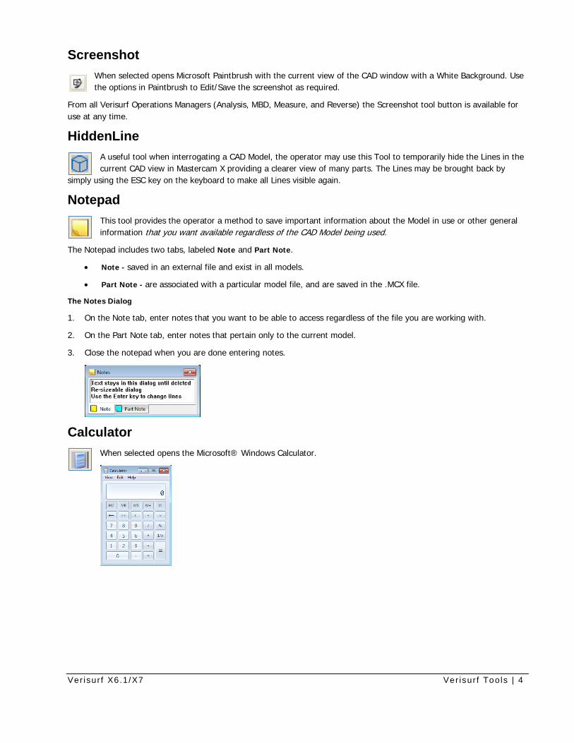
Calculator When selected opens the Microsoft® Windows Calculator.
Ver isur f X6.1/X7 Ver isur f Tools | 5
Verisurf Hole Axis The Hole-Axis tool allows you to construct the elements of a circle – including the circumferential curve, center point and axis – from a hole-type feature in a model. The elements of the constructed circle become elements of the CAD model.
Measurement processes that requires Hole measurement the CAD Model being used will not have the correct information required for the Report Manager to report Hole location, radius etc.
For instance; a CAD Model that contains only Surfaces will not correctly load Hole location information automatically into the Verisurf Report Manager, however the use of Verisurf Hole-Axis easily creates the information that is required.
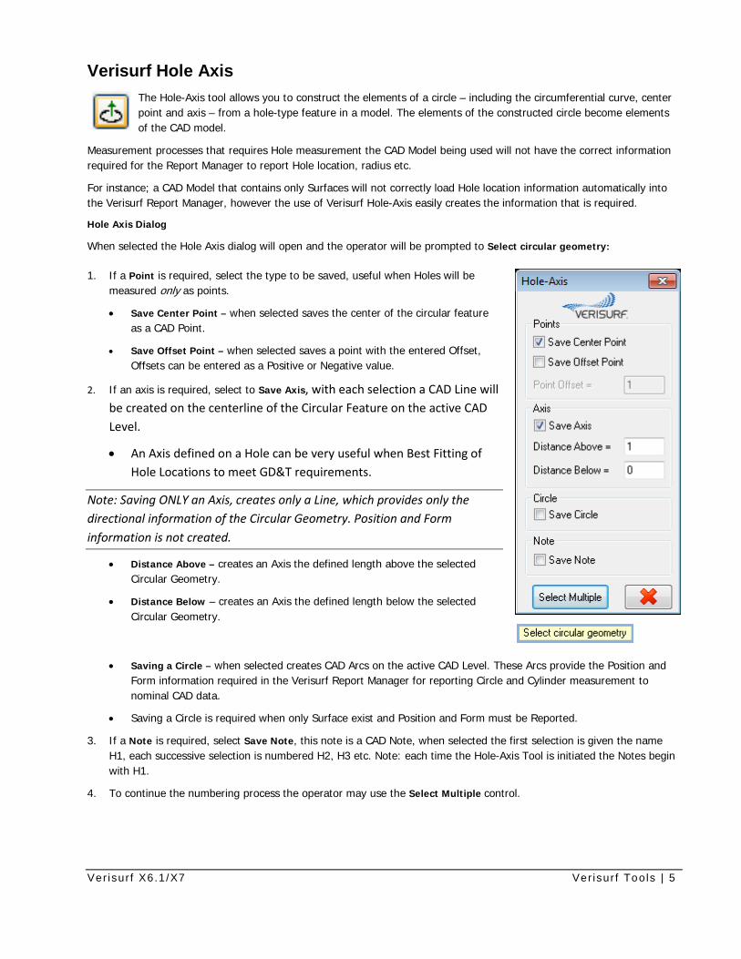
Hole Axis Dialog
When selected the Hole Axis dialog will open and the operator will be prompted to Select circular geometry:
1. If a Point is required, select the type to be saved, useful when Holes will be measured only as points.
• Save Center Point – when selected saves the center of the circular feature as a CAD Point.
• Save Offset Point – when selected saves a point with the entered Offset, Offsets can be entered as a Positive or Negative value.
2. If an axis is required, select to Save Axis, with each selection a CAD Line will be created on the centerline of the Circular Feature on the active CAD Level.
• An Axis defined on a Hole can be very useful when Best Fitting of Hole Locations to meet GD&T requirements.
Note: Saving ONLY an Axis, creates only a Line, which provides only the directional information of the Circular Geometry. Position and Form information is not created.
• Distance Above – creates an Axis the defined length above the selected Circular Geometry.
• Distance Below – creates an Axis the defined length below the selected Circular Geometry.
• Saving a Circle – when selected creates CAD Arcs on the active CAD Level. These Arcs provide the Position and Form information required in the Verisurf Report Manager for reporting Circle and Cylinder measurement to nominal CAD data.
• Saving a Circle is required when only Surface exist and Position and Form must be Reported.
3. If a Note is required, select Save Note, this note is a CAD Note, when selected the first selection is given the name H1, each successive selection is numbered H2, H3 etc. Note: each time the Hole-Axis Tool is initiated the Notes begin with H1.
4. To continue the numbering process the operator may use the Select Multiple control.
Ver isur f X6.1/X7 Ver isur f Tools | 6
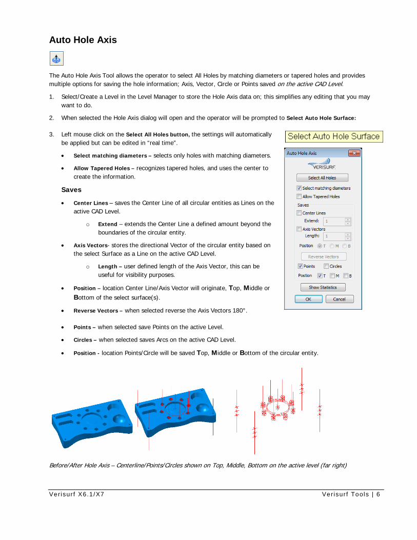
Auto Hole Axis
The Auto Hole Axis Tool allows the operator to select All Holes by matching diameters or tapered holes and provides multiple options for saving the hole information; Axis, Vector, Circle or Points saved on the active CAD Level.
1. Select/Create a Level in the Level Manager to store the Hole Axis data on; this simplifies any editing that you may want to do.
2. When selected the Hole Axis dialog will open and the operator will be prompted to Select Auto Hole Surface:
3. Left mouse click on the Select All Holes button, the settings will automatically be applied but can be edited in “real time”.
• Select matching diameters – selects only holes with matching diameters.
• Allow Tapered Holes – recognizes tapered holes, and uses the center to create the information.
Saves
• Center Lines – saves the Center Line of all circular entities as Lines on the active CAD Level.
o Extend – extends the Center Line a defined amount beyond the boundaries of the circular entity.
• Axis Vectors- stores the directional Vector of the circular entity based on the select Surface as a Line on the active CAD Level.
o Length – user defined length of the Axis Vector, this can be useful for visibility purposes.
• Position – location Center Line/Axis Vector will originate, Top, Middle or Bottom of the select surface(s).
• Reverse Vectors – when selected reverse the Axis Vectors 180°.
• Points – when selected save Points on the active Level.
• Circles – when selected saves Arcs on the active CAD Level.
• Position - location Points/Circle will be saved Top, Middle or Bottom of the circular entity.
Before/After Hole Axis – Centerline/Points/Circles shown on Top, Middle, Bottom on the active level (far right)
Ver isur f X6.1/X7 Ver isur f Tools | 7
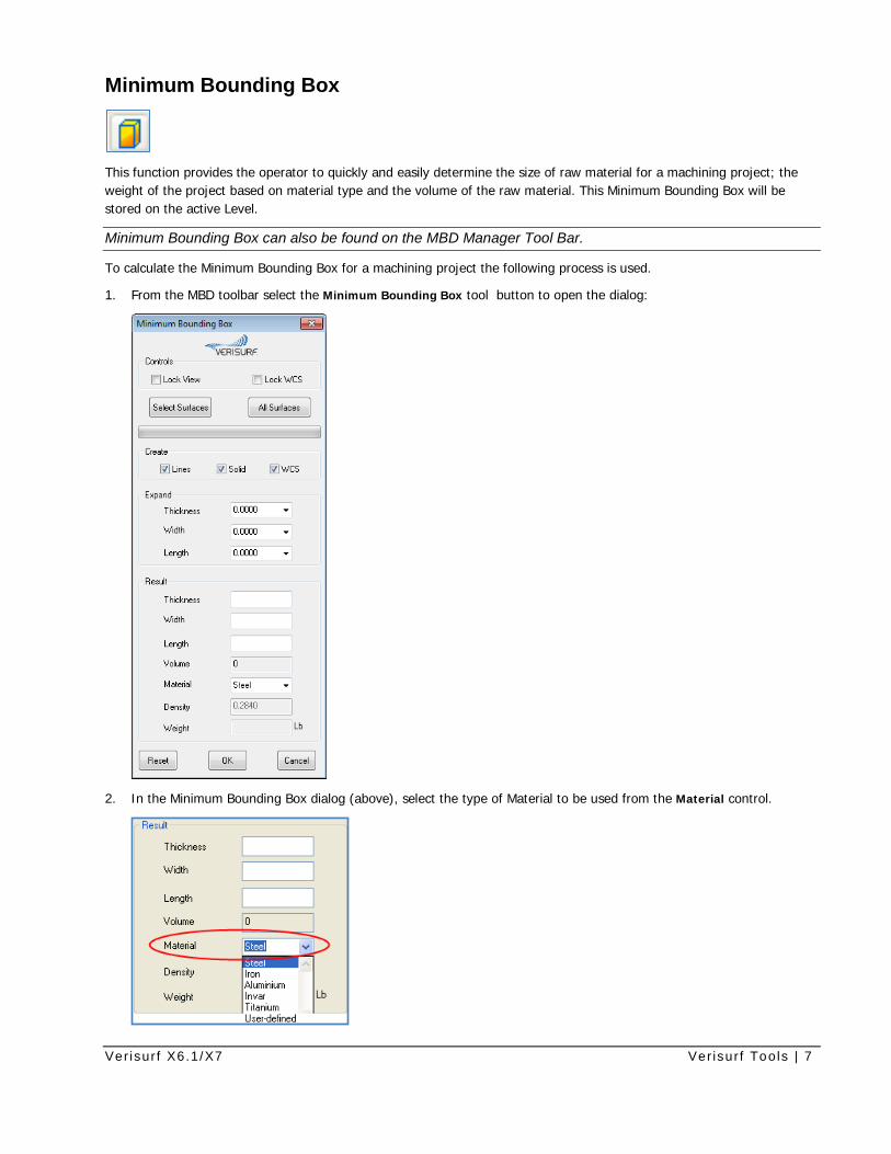
Minimum Bounding Box
This function provides the operator to quickly and easily determine the size of raw material for a machining project; the weight of the project based on material type and the volume of the raw material. This Minimum Bounding Box will be stored on the active Level.
Minimum Bounding Box can also be found on the MBD Manager Tool Bar.
To calculate the Minimum Bounding Box for a machining project the following process is used.
1. From the MBD toolbar select the Minimum Bounding Box tool button to open the dialog:
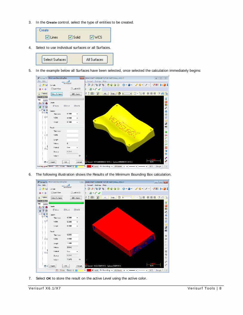
2. In the Minimum Bounding Box dialog (above), select the type of Material to be used from the Material control.
Ver isur f X6.1/X7 Ver isur f Tools | 8
3. In the Create control, select the type of entities to be created.
4. Select to use individual surfaces or all Surfaces.
5. In the example below all Surfaces have been selected, once selected the calculation immediately begins:
6. The following illustration shows the Results of the Minimum Bounding Box calculation.
7. Select OK to store the result on the active Level using the active color.
Ver isur f X6.1/X7 Ver isur f Tools | 9
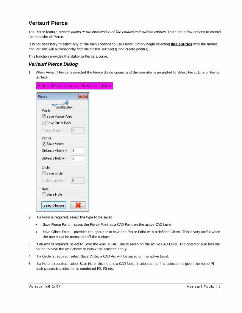
Verisurf Pierce The Pierce feature creates points at the intersection of line entities and surface entities. There are a few options to control the behavior of Pierce.
It is not necessary to select any of the menu options to use Pierce. Simply begin selecting line entities with the mouse and Verisurf will automatically find the closest surface(s) and create point(s).
This function provides the ability to Pierce a curve.
Verisurf Pierce Dialog 1. When Verisurf Pierce is selected the Pierce dialog opens, and the operator is prompted to Select Point, Line or Pierce
Surface.
2. If a Point is required, select the type to be saved.
• Save Pierce Point – saves the Pierce Point as a CAD Point on the active CAD Level.
• Save Offset Point – provides the operator to save the Pierce Point with a defined Offset. This is very useful when the part must be measured off the surface.
3. If an axis is required, select to Save the Axis, a CAD Line is saved on the active CAD Level. The operator also has the option to save the axis above or below the selected entity.
4. If a Circle is required, select Save Circle, a CAD Arc will be saved on the active Level.
5. If a Note is required, select Save Note, this note is a CAD Note, if selected the first selection is given the name P1, each successive selection is numbered P2, P3 etc.
Ver isur f X6.1/X7 Ver isur f Tools | 10
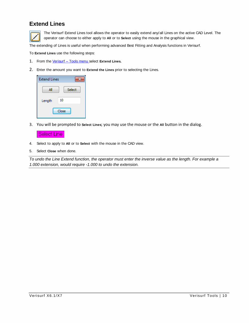
Extend Lines The Verisurf Extend Lines tool allows the operator to easily extend any/all Lines on the active CAD Level. The operator can choose to either apply to All or to Select using the mouse in the graphical view.
The extending of Lines is useful when performing advanced Best Fitting and Analysis functions in Verisurf.
To Extend Lines use the following steps:
1. From the Verisurf – Tools menu select Extend Lines.
2. Enter the amount you want to Extend the Lines prior to selecting the Lines.
3. You will be prompted to Select Lines; you may use the mouse or the All button in the dialog.
4. Select to apply to All or to Select with the mouse in the CAD view.
5. Select Close when done.
To undo the Line Extend function, the operator must enter the inverse value as the length. For example a 1.000 extension, would require -1.000 to undo the extension.
Ver isur f X6.1/X7 Ver isur f Tools | 11
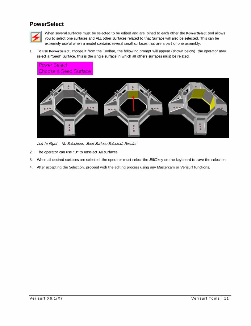
PowerSelect When several surfaces must be selected to be edited and are joined to each other the PowerSelect tool allows you to select one surfaces and ALL other Surfaces related to that Surface will also be selected. This can be extremely useful when a model contains several small surfaces that are a part of one assembly.
1. To use PowerSelect, choose it from the Toolbar, the following prompt will appear (shown below), the operator may select a “Seed” Surface, this is the single surface in which all others surfaces must be related.
Left to Right – No Selections, Seed Surface Selected, Results
2. The operator can use “U” to unselect All surfaces.
3. When all desired surfaces are selected, the operator must select the ESC key on the keyboard to save the selection.
4. After accepting the Selection, proceed with the editing process using any Mastercam or Verisurf functions.
Ver isur f X6.1/X7 Ver isur f Tools | 12
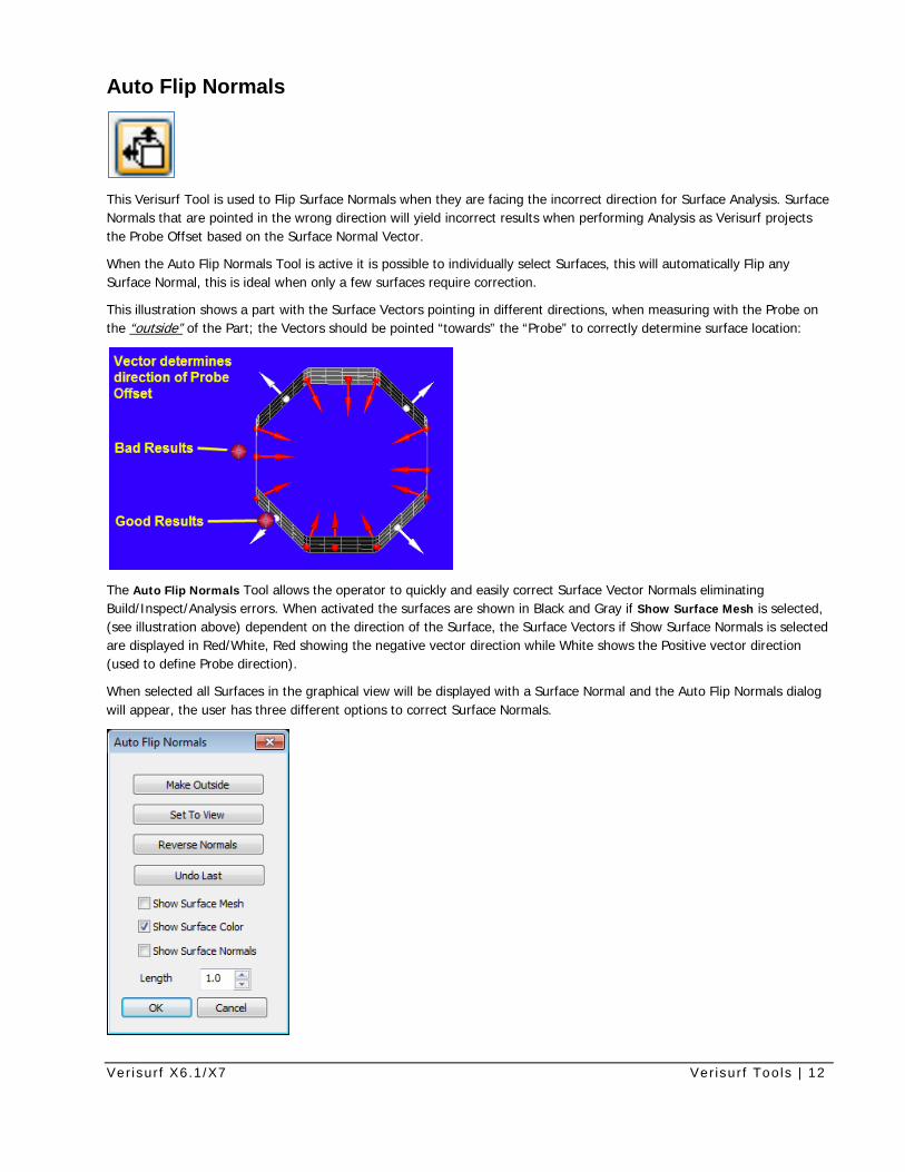
Auto Flip Normals
This Verisurf Tool is used to Flip Surface Normals when they are facing the incorrect direction for Surface Analysis. Surface Normals that are pointed in the wrong direction will yield incorrect results when performing Analysis as Verisurf projects the Probe Offset based on the Surface Normal Vector.
When the Auto Flip Normals Tool is active it is possible to individually select Surfaces, this will automatically Flip any Surface Normal, this is ideal when only a few surfaces require correction.
This illustration shows a part with the Surface Vectors pointing in different directions, when measuring with the Probe on the “outside” of the Part; the Vectors should be pointed “towards” the “Probe” to correctly determine surface location:
The Auto Flip Normals Tool allows the operator to quickly and easily correct Surface Vector Normals eliminating Build/Inspect/Analysis errors. When activated the surfaces are shown in Black and Gray if Show Surface Mesh is selected, (see illustration above) dependent on the direction of the Surface, the Surface Vectors if Show Surface Normals is selected are displayed in Red/White, Red showing the negative vector direction while White shows the Positive vector direction (used to define Probe direction).
When selected all Surfaces in the graphical view will be displayed with a Surface Normal and the Auto Flip Normals dialog will appear, the user has three different options to correct Surface Normals.
Ver isur f X6.1/X7 Ver isur f Tools | 13
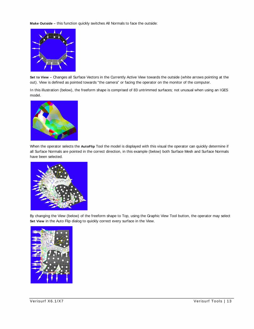
Make Outside – this function quickly switches All Normals to face the outside:
Set to View – Changes all Surface Vectors in the Currently Active View towards the outside (white arrows pointing at the out). View is defined as pointed towards “the camera” or facing the operator on the monitor of the computer.
In this illustration (below), the freeform shape is comprised of 83 untrimmed surfaces; not unusual when using an IGES model.
When the operator selects the AutoFlip Tool the model is displayed with this visual the operator can quickly determine if all Surface Normals are pointed in the correct direction, in this example (below) both Surface Mesh and Surface Normals have been selected.
By changing the View (below) of the freeform shape to Top, using the Graphic View Tool button, the operator may select Set View in the Auto Flip dialog to quickly correct every surface in the View.
Ver isur f X6.1/X7 Ver isur f Tools | 14
Results seen below after using the Set View command, note tha all bad vectors that were visible in the Top View (above), are turned to the Outside. If the part is to be measured or analyzed to the outer surface this would be the correct configuration for the measurement/analysis job.
Reverse Normals – this command switches ALL active Surface Normals, this is ideal when all the visible Surfaces are incorrect. Using the Level Manager to separate surfaces can be useful when large numbers of Surfaces exist.
Undo Last – use this to Undo the last Auto Flip command.
Name Points This feature is a convenient way to create labels to identify various points in your database, such as tooling ball locations. Verisurf will consider note entities as points, and can compare those notes to your CAD model. When notes are used instead of points, the reports generated by Verisurf will contain the text of the notes. This makes the reports easier to read and understand.
Please Note: These labels are created as separate entities from the points that they represent, and are not associated with the points in any way, other than that they have the same location in space.
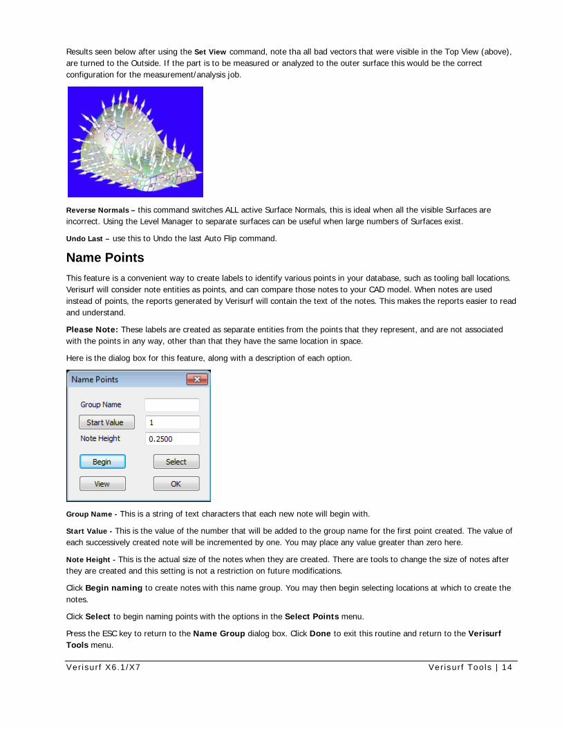
Here is the dialog box for this feature, along with a description of each option.
Group Name - This is a string of text characters that each new note will begin with.
Start Value - This is the value of the number that will be added to the group name for the first point created. The value of each successively created note will be incremented by one. You may place any value greater than zero here. Note Height - This is the actual size of the notes when they are created. There are tools to change the size of notes after they are created and this setting is not a restriction on future modifications.
Click Begin naming to create notes with this name group. You may then begin selecting locations at which to create the notes.
Click Select to begin naming points with the options in the Select Points menu.
Press the ESC key to return to the Name Group dialog box. Click Done to exit this routine and return to the Verisurf Tools menu.
Ver isur f X6.1/X7 Ver isur f Tools | 15
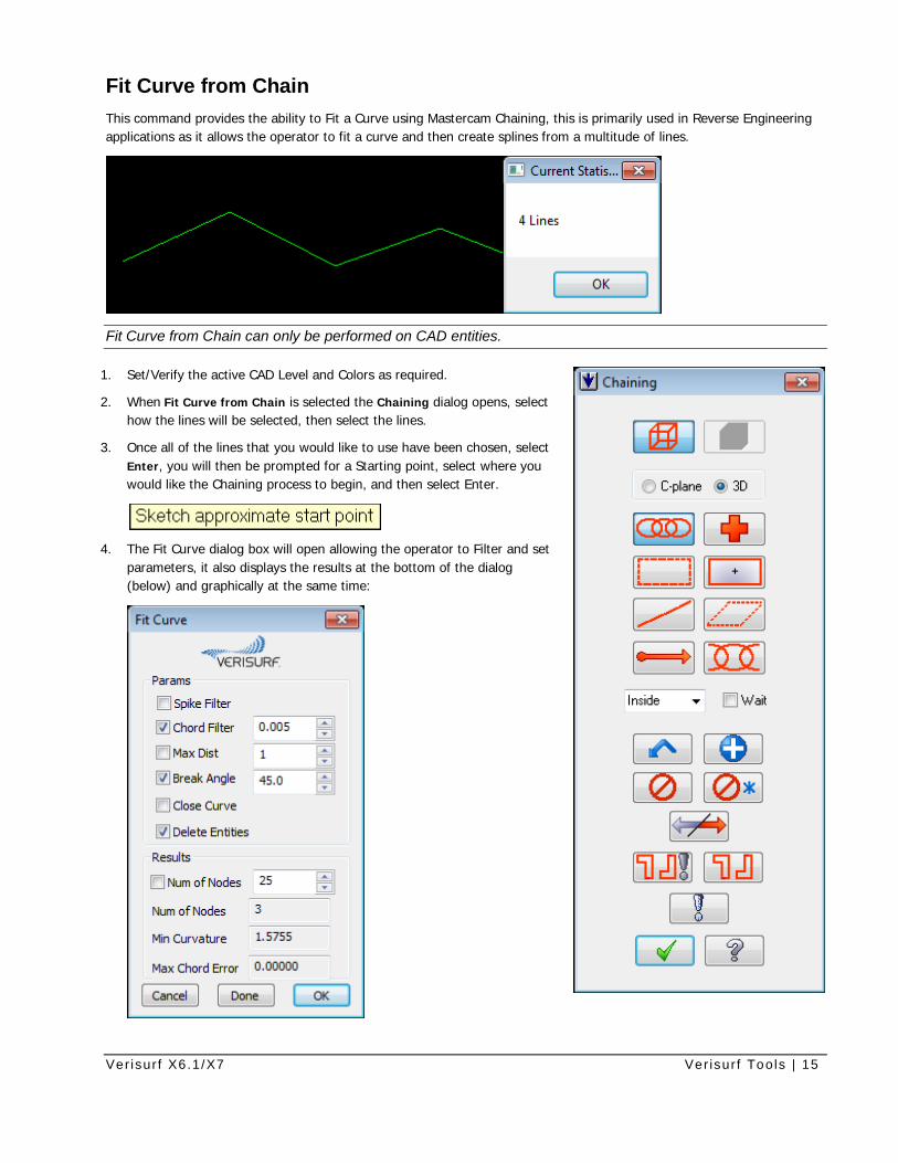
Fit Curve from Chain This command provides the ability to Fit a Curve using Mastercam Chaining, this is primarily used in Reverse Engineering applications as it allows the operator to fit a curve and then create splines from a multitude of lines.
Fit Curve from Chain can only be performed on CAD entities.
1. Set/Verify the active CAD Level and Colors as required.
2. When Fit Curve from Chain is selected the Chaining dialog opens, select how the lines will be selected, then select the lines.
3. Once all of the lines that you would like to use have been chosen, select Enter, you will then be prompted for a Starting point, select where you would like the Chaining process to begin, and then select Enter.
4. The Fit Curve dialog box will open allowing the operator to Filter and set parameters, it also displays the results at the bottom of the dialog (below) and graphically at the same time:
Ver isur f X6.1/X7 Ver isur f Tools | 16
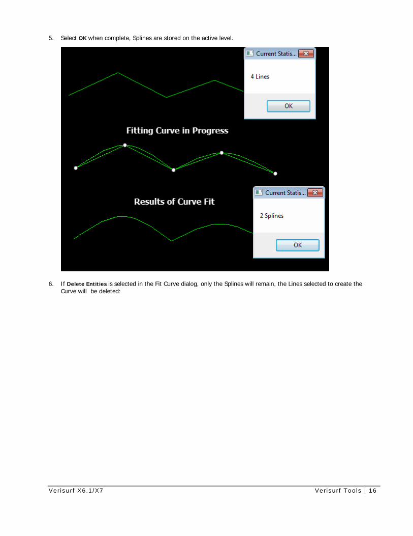
5. Select OK when complete, Splines are stored on the active level.
6. If Delete Entities is selected in the Fit Curve dialog, only the Splines will remain, the Lines selected to create the Curve will be deleted:
Ver isur f X6.1/X7 Ver isur f Tools | 17
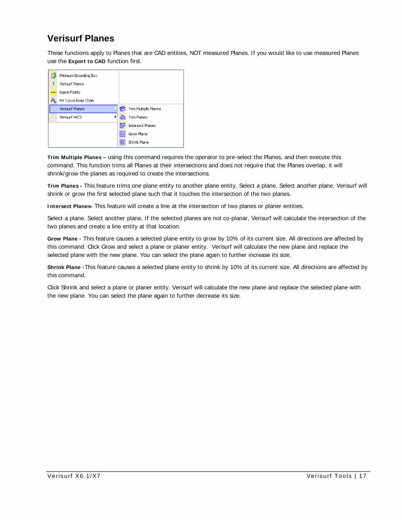
Verisurf Planes These functions apply to Planes that are CAD entities, NOT measured Planes. If you would like to use measured Planes use the Export to CAD function first.
Trim Multiple Planes – using this command requires the operator to pre-select the Planes, and then execute this command. This function trims all Planes at their intersections and does not require that the Planes overlap, it will shrink/grow the planes as required to create the intersections.
Trim Planes - This feature trims one plane entity to another plane entity. Select a plane. Select another plane. Verisurf will shrink or grow the first selected plane such that it touches the intersection of the two planes.
Intersect Planes- This feature will create a line at the intersection of two planes or planer entities.
Select a plane. Select another plane. If the selected planes are not co-planar, Verisurf will calculate the intersection of the two planes and create a line entity at that location.
Grow Plane - This feature causes a selected plane entity to grow by 10% of its current size. All directions are affected by this command. Click Grow and select a plane or planer entity. Verisurf will calculate the new plane and replace the selected plane with the new plane. You can select the plane again to further increase its size.
Shrink Plane -This feature causes a selected plane entity to shrink by 10% of its current size. All directions are affected by this command.
Click Shrink and select a plane or planer entity. Verisurf will calculate the new plane and replace the selected plane with the new plane. You can select the plane again to further decrease its size.
Ver isur f X6.1/X7 Ver isur f Tools | 18
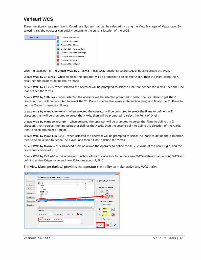
Verisurf WCS These functions create new World Coordinate System that can be selected by using the View Manager of Mastercam. By selecting F9, the operator can quickly determine the current location of the WCS.
With the exception of the Create WCS by 3 Points, these WCS functions require CAD entities to create the WCS.
Create WCS by 3 Points – when selected the operator will be prompted to select the Origin, then the Point along the X axis, then the point to define the XY Plane.
Create WCS by 2 Lines- when selected the operator will be prompted to select a Line that defines the X axis, then the Line that defines the Y axis.
Create WCS by 3 Planes – when selected the operator will be selected prompted to select the first Plane to get the Z direction, then will be prompted to select the 2nd Plane to define the X-axis (Intersection Line) and finally the 3rd Plane to get the Origin (Intersection Point).
Create WCS by Plane Line Point – when selected the operator will be prompted to select the Plane to define the Z direction, then will be prompted to select the X Axis, then will be prompted to select the Point of Origin.
Create WCS by Plane Axis Origin – when selected the operator will be prompted to select the Plane to define the Z direction, then to select the first point that defines the X axis, then the second point to define the direction of the X axis, then to select the point of origin.
Create WCS by Plane Line Line – when selected the operator will be prompted to select the Plane to define the Z direction, then to select a Line to define the X axis, and then a Line to define the Y axis.
Create WCS by Matrix – this advanced function allows the operator to define the X, Y, Z value of the new Origin, and the directional vectors of I, J, K.
Create WCS by XYZ ABC – this advanced function allows the operator to define a new WCS relative to an existing WCS and defining a New Origin value and new Rotations about A, B, C.
The View Manager (below) provides the operator the ability to make active any WCS active:
Ver isur f X6.1/X7 Ver isur f Tools | 19
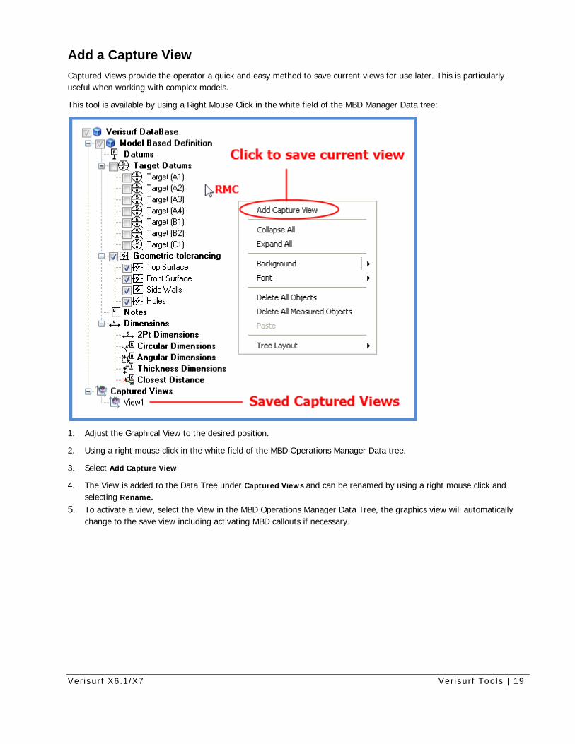
Add a Capture View Captured Views provide the operator a quick and easy method to save current views for use later. This is particularly useful when working with complex models.
This tool is available by using a Right Mouse Click in the white field of the MBD Manager Data tree:
1. Adjust the Graphical View to the desired position.
2. Using a right mouse click in the white field of the MBD Operations Manager Data tree.
3. Select Add Capture View
4. The View is added to the Data Tree under Captured Views and can be renamed by using a right mouse click and selecting Rename.
5. To activate a view, select the View in the MBD Operations Manager Data Tree, the graphics view will automatically change to the save view including activating MBD callouts if necessary.