vermont agency of transportation program...
TRANSCRIPT
Vermont Agency of Transportation Program Management Division Materials and Research Section
To: Ken Upmal, Project Manager, Highway Safety and Design From: Thomas D. Eliassen, Transportation Geologist via Christopher C.
Benda, Soils and Foundations Engineer Date: February 20, 2014 Subject: Coventry STP 0113(66) - Rock Slope Stability Recommendations The VTrans geologist has conducted a rock slope stability investigation at an existing rock slope located adjacent to the southbound travel lane at mile marker 3.35 of U.S. 5 in the town of Coventry (Figure 1). This project developed from a request by VTrans Maintenance District 9 as rock overhangs the roadway, sight distance is poor, rock periodically falls onto the roadway and there is little to no catchment ditch at the toe of slope. This rock slope was identified in the VTrans 2007 Rockfall Hazard Rating (RHRS) study as an “A” cut with a RHRS score of 595. This score is the eleventh highest noted in the study. “A” ranked slopes represent slopes where rockfall is expected to occur and reach the roadway. This soil and vegetation (mostly cedar) covered slope has a natural surface that lay’s at a 40° angle and continues at this angle for about 900-feet up the slope. At the roadway, this slope has been cut at an angle of about 75° with a cut height of 30 to 50-feet. There is inadequate catchment ditch here and there are large areas of overhanging rock on the slope.
Figure 1: Project Location The roadway occupies a narrow corridor between the subject rock cut on the west and the Black River to the east. The roadway here is on a horizontal curve and consists of 29 feet of pavement with no shoulder on the southbound lane. The posted speed limit here is 50 miles-per-hour and measured sight distance is 155 feet. The AADT on this roadway in
Coventry STP 0113(66) Project Location

Coventry STP 0113(66) Rock Slope Remediation Report February 20, 2014
Page 2 of 14
2012 was 2,600 vehicles per day. This roadway is frequently used by heavy trucks (logging trucks and dump trucks) and traffic has been observed traveling at excessive speeds. The combination of poor sight distance, lack of adequate catchment ditch, poor slope conditions and propensity for vehicles to exceed the speed limit at this location increases the likelihood that fallen rock could impact the traveling public. A photograph of a portion of the rock slope is presented as Figure 2.
Figure 2: Photograph of rock cut looking south. Notice poor ditch, overhanging rock
slabs and heavy vegetation on slope.
GEOLOGY According to the state geologic map1, bedrock in the project area consists of rocks of the Ayers Cliff and Barton River Members of the Waits River Formation. The Ayers Cliff Member consists of siliceous crystalline limestone containing thin beds of slate and phyllite and the Barton River Member is made up of interbedded siliceous crystalline limestone and sercite-quartz-chlorite phyllite.
1 Doll, C.G., Cady, W.M., Thompson Jr., J.B., and Billings, M.P., 1961, Centennial Geologic Map of Vermont: State of Vermont, scale 1:250,000.

Coventry STP 0113(66) Rock Slope Remediation Report February 20, 2014
Page 3 of 14
Slate and phyllite of the Ayers Cliff Member makes up the bulk of rock at the project location while the contact with the Barton River Member occurs approximately 150 feet up-slope of the toe. Figure 3 shows a portion of the 1961 bedrock map and the location of the project.
Figure 3: Bedrock geologic map of project area. The Ayers Cliff Member of the Waite River Formation is labeled Dwa and the Barton River Member is labeled Dwb. Formation/Member contacts are depicted by solid black lines.
The most prominent discontinuity in the rock is cleavage. Cleavage planes within the phyllite and slate (C1) dips toward the west northwest at angles between 50° and 70°. These cleavage planes dip steeply into the slope and where the rock slope has been cut, slabs of rock develop resulting in toppling failure. Two joint systems are present in this rock. One set (J1) dips from 30° to 50° in an east southeasterly direction and the other joint set (J2) dips almost vertically in a north northeasterly direction. A discussion of the orientation of planar features in this rock cut and how it relates to rockfall potential is presented later in this report. FIELD ACTIVITIES Discontinuity Mapping
Measurements of discontinuities in rock at this cut were made using a Brunton Geo™ Pocket Transit. This compass allows for the measurement of the orientation of planar features in the rock. Measurements were made at a number of locations near the base of the cut (within reach by the geologist). These measurements were used in stereographic analysis (discussed below) to evaluate the kinematic possibility of rock failure. A total of 23 individual measurements were made (dip and dip direction) and this data was input into the program RockPack III that was developed by Dr. Skip Watts of Radford University in Virginia. RockPack allows for the representation of planar features and how these features and intersection of features relate to kinematic stability using
Coventry STP 0113(66) Project Location

Coventry STP 0113(66) Rock Slope Remediation Report February 20, 2014
Page 4 of 14
Markland Test Plot methods. A discussion of the stereographic and Markland Test Plot methods are presented in Appendix A.
Slope Profiles
As a general practice, VTrans usually measures and records two dimensional slope profiles at various stationing using a Laser Technology, Inc. slope profiler system. These profiles are used to measure two dimensional coordinates of the cut slope at a number of Stations. These profiles are used along with rockfall modeling software in evaluating the potential for falling rock to reach the roadway and to estimate design parameters such as bounce height and total kinetic energies of individual rock blocks. Due to the heavy vegetation on this slope, limited exposures of rock were profiled.
Field Tests (Point Load Testing)
Point load testing was not performed during this study. LABORATORY TESTING Petrographic Analysis
Petrographic analysis was not performed on this rock as part of this study.
Uniaxial Compression Testing
Uniaxial compression testing was not performed on this rock as part of this study. Based on published information, the expected uniaxial compressive strength of phyllite/slate is from 5,000 psi to 15,000 psi. DATA ANALYSIS Rockfall Analysis
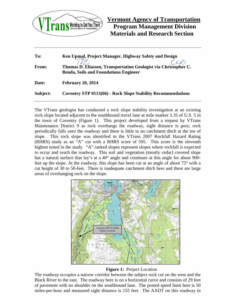
Rockfall analysis was performed utilizing RocFall® software developed by the company Rocscience. RocFall® is a statistical analysis program designed to assist with the risk assessment of rockfalls. The program simulates the path of falling rock based on a slope profile input and determines energy, velocity, bounce height and the location of fallen rock end points. Profiles at three locations were measured. Two of the three profiles show extensive overhanging conditions. Analysis conducted in RocFall® indicates that individual rocks which may fall from the slope face will end up on and across the roadway. Figure 4 shows the slope profile near the northern portion of the rock cut.
Coventry STP 0113(66) Rock Slope Remediation Report February 20, 2014
Page 5 of 14
Figure 4: a) Profile of rock slope showing large overhanging rock face in upper portion of the rock exposure. b) RocFall® analysis output. Red traces reflect rockfall trajectories.
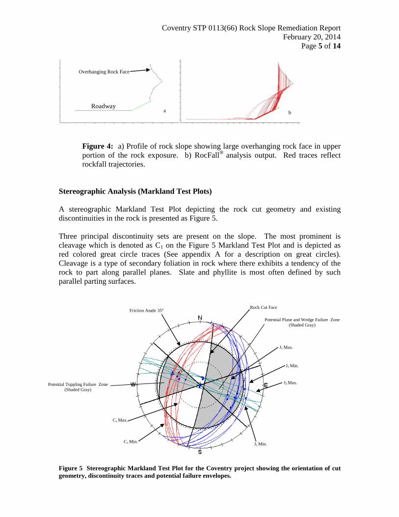
Stereographic Analysis (Markland Test Plots)
A stereographic Markland Test Plot depicting the rock cut geometry and existing discontinuities in the rock is presented as Figure 5. Three principal discontinuity sets are present on the slope. The most prominent is cleavage which is denoted as C1 on the Figure 5 Markland Test Plot and is depicted as red colored great circle traces (See appendix A for a description on great circles). Cleavage is a type of secondary foliation in rock where there exhibits a tendency of the rock to part along parallel planes. Slate and phyllite is most often defined by such parallel parting surfaces.
Figure 5 Stereographic Markland Test Plot for the Coventry project showing the orientation of cut geometry, discontinuity traces and potential failure envelopes.
C1 Max.
C1 Min.
J1 Max.
J1 Min.
J2 Max.
J2 Min.
Friction Angle 35°
Potential Plane and Wedge Failure Zone (Shaded Gray)
Rock Cut Face
Potential Toppling Failure Zone (Shaded Gray)
Roadway
Overhanging Rock Face
a b

Coventry STP 0113(66) Rock Slope Remediation Report February 20, 2014
Page 6 of 14
The orientation of cleavage surfaces measured on the slope dips from 50° to 70° toward the west northwest. Two joint sets are present in the rock (J1 and J2). Joints are fractures in rock usually vertical to transverse to bedding that exhibits no apparent separation between adjoining blocks. Joint surface J1 (blue great circles) dips from 30° to 50° in an east southeasterly direction and J2 (green great circles) dips near vertical in a north northeasterly direction. In order to evaluate for kinematic sliding potential, a method of selecting the range of great circles for each discontinuity set was used as described in Section 4.0 of the RockPack III manual. Three types of rock failure modes are represented at this location (Plane, Wedge and Toppling). These following conditions must be met for kinematic failure conditions:
Plane Failure Plane failure in rock slopes is possible when the following conditions are met:
1. The dip of the discontinuity is toward the slope face at an angle greater than the internal angle of friction of the particular rock under investigation,
2. The discontinuity daylights out of the slope, and 3. The dip direction is within 20° ± of the dip direction of the slope face.
Wedge Failure Wedge failure is possible when the intersection of two or more discontinuities is such that the line of intersection of these planes trends out of the slope face at an angle greater than the internal friction angle of friction of the particular rock under investigation. Toppling Failure Toppling failure involves overturning or rotation of rock layers. Steeply dipping discontinuities that dip away from the slope surface can lead to toppling failure when the critical angle of the release surface places the center of gravity of the slabs out over the open cut face.
As can be seen on Figure 5, all three potential failure modes are present at the subject rock slope. The red great circle traces (cleavage C1) represent dip directions and magnitudes of dip of possible toppling conditions as the normals to the traces (blue dots on the plot) occur in the gray shaded area of the Markland Test Plot. The slabs of rock that are susceptible to toppling can be seen clearly in Figure 2. Toppling is the most prominent failure mode at this location. The normals to clusters of blue colored great circles representing joint set J1 fall within the plane failure area (shaded gray) on the plot and are within the 20° ± critical zone. Traces of joint set J2 act as release surfaces for wedge failures defined by the intersection of J1 and J2 great circle traces.

Coventry STP 0113(66) Rock Slope Remediation Report February 20, 2014
Page 7 of 14
Cleavage C1
Stability Analysis
Figure 6: Sketch showing the development of toppling failure on the subject slope. The predominant type of failure at this location is toppling. The excavation along the 80° cut that was constructed in 1931 (Coventry-Project No. 130A) has undermined slope, setting-up ideal conditions for toppling. Over time, rock slabs rotate out of the slope as the slab center of gravity shifts toward the roadway. A sketch, shown as Figure 6 shows the likely development of toppling failure on this project. The toppling failure shown in the sketch represents block toppling where strong tabular slabs of rock rotate out of the slope individually and the jointing at the base of the slabs serve only as a release plane for the slabs to rotate out on. Although plane failure was identified associated with joint set J1, These joint surfaces are short and discontinuous and is not expected to result in a classical plane failure manner. As mentioned above, this joint set provides the release surfaces needed for the block toppling to rotate about. Because joint set J1 is discontinuous, wedges formed by the intersection of J1 and J2 are small in scale and as such only provide for the release of smack blocks of rock. Toppling stability analysis was performed using the toppling module of the RockPack III computer program. In the RockPack III program, quantitative analyses presented in Seegmiller, 19822 is used to calculate the sum of moments for each rock slab. Input parameters include the length and thickness for each rock slab and the angle the slab makes with horizontal. A diagram showing the forces acting on a toppling slap is presented as Figure 7.
2 Seegmiller, B.L. 1982. Artificial Support of Rock Slopes. In Stability in Surface Mining, Vol. 3. Edited by C.O. Brawner. New York: Society of Mining Engineers of the American Institute of Mining, Metallurgical and Petroleum Engineers.
Joint Set J1

Coventry STP 0113(66) Rock Slope Remediation Report February 20, 2014
Page 8 of 14
Figure 7: Force diagram for toppling analysis.
For the toppling analysis, the height of slab was estimated to be 15-feet, the thickness of slab 0.2-feet and angle of slab 40°. The unit weight of rock used in these calculations was 170 lbs/ft3. Input and output for the analysis is presented below: Topple Failure Analysis Input Data Height of Block = 15 ft Width of Block = 0.2 ft Angle of Block = 40 ° Density of Water = 62.4 lb(f)/ft ³ Density of Rock = 170 lb(f)/ft ³ Topple Failure Analysis Output Data The Sum of the Moments = 2419.59 lb(f).ft This indicates that the slope is UNSAFE MITIGATION ALTERNATIVES Presented below is a discussion of possible mitigation alternatives. These discussions address various common methods that are used to eliminate or greatly reduce the risk associated with rockfall events. Each slope has its own unique set of conditions which will influence the most appropriate and cost effective mitigation action.

Coventry STP 0113(66) Rock Slope Remediation Report February 20, 2014
Page 9 of 14
Stabilization
Stabilization involves eliminating or minimizing the possibility of rockfall events by removal of all or portions of the rock exposure, reinforcement of the slope face or protection such as providing an effective catchment ditch. Removal techniques include:
• Blasting the slope at shallower angles and scaling of the loose blocks of rock that may be present.
• Trim blasting of select rock blocks. • Hand or machine scaling of loose rock on the face of the slope.
Reinforcement techniques include:
• Securing masses of rock either by doweling/bolting, • Applying shotcrete or constructing some type of buttress or • Providing drainage by drilling into the rock to relieve water pressure.
Protective measures include:
• Constructing catchment ditches, • Installation of wire or wire rope drapes, • Erection of rockfall fencing, • Construction of barriers and • Cable lashing of individual or masses of loose rock.
Removal Limited rock removal is recommended for this slope.
Blasting Based on kinematic analysis, it has been determined that in order to eliminate day lighting of the plane features on the slope, a slope angle of approximately 40° would be required. The existing slope extends up-hill for about 900-feet. VTrans Right-of-Way only extends 50-feet from the center of the roadway. Both the long up-hill extent of this slope and the limited ROW available, make laying this slope back to an angle that would provide stabilization impractical. Hand Scaling
Hand scaling utilizing rope access techniques is one of the mitigation techniques considered for this slope. Hand scaling could include prying loose rock off of the slope surface utilizing steel scaling bars, air bags, Boulder Blaster® or hydraulic splitters/jacks. Hand scaling is most effectively performed using rope access techniques whereby scaling crew members rappel down each section of the slope as they scale. Hand scaling using rope access techniques allows for a small footprint in terms of equipment on the roadway in the work zone.

Coventry STP 0113(66) Rock Slope Remediation Report February 20, 2014
Page 10 of 14
Based on observations made of the slope conditions and site access, hand scaling would be required to prepare the slope for other mitigation techniques (discussed below). It is estimated that a scaling crew of 4 (3-scalers and 1-foreman) can scale the length of the slope in about one week.
Machine Scaling
Machine scaling involves the removal of rock using excavators, hoe rams or other heavy equipment. Care should be taken not to over aggressively remove rock that might lead to the development of overhangs. As with hand scaling, some machine scaling would be required for this slope in order to prepare the slope for other mitigation techniques (discussed below). Approximately 50 yd3 of material would need to be removed.
Reinforcement
Rock Doweling
Rock doweling involves drilling a hole into the rock to a depth adequate to penetrate beyond any discontinuity that may lead to slope failure. A steel bar with centralizers is then inserted into the hole and the annulus filled with a cement or epoxy grout. Rock dowels are un-tensioned and can be installed as singular anchors or in a pattern to supply the needed resistive force to a slope. Because of the way the rock at this site breaks (into relatively thin planar slabs), rock doweling or bolting alone would not be an appropriate mitigation method. Doweling/bolting works well when a well defined rock of rock exists. Phyllite and slate are relatively weak rock types and as such, attempts to drill and dowel/bolt them would result in crushing of the rock face and subsequent loss of tension. Used however in conjunction with the application of a shotcrete cover, rock doweling can work well to provide stabilization to masses of rock beneath the shotcrete surface. It is expected that the installation of pattern rock doweling on an about 10-foot spacing through the shotcrete will provide for the stabilization of loose masses of rock within the slope.
Rock Bolting
Rock bolting consists of drilling and installing a tensioned rock bolt through unstable blocks into sound rock in the slope. Rock bolting is appropriate when there has been some dilation along a critical discontinuity as the tensioning forces act to increase cohesion at the failure interface. The same issues regarding rock doweling apply to rock bolting techniques in this type of rock. Rock bolting is not recommended for this project.

Coventry STP 0113(66) Rock Slope Remediation Report February 20, 2014
Page 11 of 14
Shotcrete
Shotcrete can be an effective mitigation method for providing surface treatment or buttress support. Surface treatment could be used to fill open joints/fractures and bind small rock blocks together. Rock doweling is often used in conjunction with surface treatments to help secure the shotcreted areas to sound rock. Drainage components such as such as drain fabric and weep holes are most often necessary to prevent water buildup behind the shotcrete. After careful consideration of all of the mitigative techniques available, it was determined that the subject slope would benefit by the application of a shotcrete surface secured to the slope by rock dowels. The shotcrete thickness will vary depending upon the geometry of the slope face, but for design purposes, it is assumed that a thickness of 6-inches will be required. Drainage
Drainage can be accomplished by drilling upward-tilting drain holes that are designed to intercept water filled joints, fractures or voids. Anytime shotcrete is applied to a slope, it is advisable to install drains. It is estimated that 200 linear feet of drill holes will be necessary.
Buttress
Buttresses can be used to provide support for overhanging rock masses as well as providing lateral support. Buttressing at the base of overhanging rock exposures is recommended. This will provide for a strong foundation for the shotcrete and will add support for overhanging masses of rock.
Protection
Ditches
The distance from the edge of roadway to the toe of slope is less than two feet in places and does not provide any catchment area for falling rock. Widening of the catchment area is not advisable as this would require excavating the toe of the slope that would be detrimental to the overall slope stability.
Mesh Drape
Netting systems consist of double-twist high strength woven wire (or steel), rock anchors, cables and clips could be attached to the slope (at the top). This allows any rock that might fall to do so underneath the mesh and drop in a controlled manner into the catchment ditch. The lack of adequate catchment at the toe of the slope and the expected size of potential rockfalls make this technique inappropriate for this location.

Coventry STP 0113(66) Rock Slope Remediation Report February 20, 2014
Page 12 of 14
Rockfall Catchment Fence
Rockfall Catchment Fences are engineered systems consisting of a wire or wire rope netting hung from steel posts with cables and breaking systems. Rockfalls are caught by the netting and the breaking system effectively reduces the velocity of the falling rock so that it prevents the rocks from reaching the roadway. Because there is limited distance between the roadway and the base of the slope, there is not enough room for such a system to be installed. Cable Lashing
Cable lashing is an effective mitigation technique for securing large individual blocks of rock. This technique involves draping steel cables over a rock mass and securing the ends of the cable to the ground using steel anchors. Cable lashing is not appropriate for this project. Retaining Wall/Barriers Retaining and barriers walls can be effective in adding support to unstable rock slopes or to provide continuity to raveling slope faces. Walls can be in the form of cast in place walls, pre-cast panels, gabion baskets, metal bin walls or other wall designs. Because of the limited distance from toe-of-slope to roadway, the use of retaining walls or barriers on this project is not recommended.
RECOMMENDATIONS Based on observations made of the subject slope, analysis of field data gathered and considerations of possible rockfall mitigation methods, we recommend applying a shotcrete facing to the cut face. The shotcrete should be strengthened by encapsulating welded wire fabric reinforcement within the shotcrete and securing the application to the slope face utilizing untensioned rock dowels. Prior to the application of the shotcrete, the slope would need to be completely free of vegetation and the slope face scaled both by hand scaling and limited machine scaling. Care should be taken to avoid removing any rock at the toe of the slope. Figure 8 is a sketch of the design concept.

Coventry STP 0113(66) Rock Slope Remediation Report February 20, 2014
Page 13 of 14
Figure 8 Simplified sketch showing the general concept for the design of the shotcrete application. Short pins and drainage holes are not shown on this sketch. A detailed design will follow this report. The following items and quantities are estimated: Clearing and Grubbing 6,400 ft2 of Slope Face Hand Scaling 50 Crew Hours (Crew of 4) Machine Scaling 20 Rental Hours Shotcrete Application 6,400 ft2 of Slope Face
Wire Fabric 6,400 ft2 of Slope Face Pins 900 Linear Feet Rock Dowels 700 Linear Feet Drain Holes 700 Linear Feet These estimates are meant to provide Highway Safety & Design with an approximation of the quantities that may be necessary. As the project design process develops, actual quantities may vary.
Shotcrete application with wire mesh support.
Rock Dowels
Joint Surfaces
Rock

Coventry STP 0113(66) Rock Slope Remediation Report February 20, 2014
Page 14 of 14
This project will require the use of a detour. The roadway at this location is narrow, sandwiched between the rock slope on the west and the Black River immediately to the east. I hope this report provides Roadway Design with information and recommendations that will advance this project in a sound engineering and cost effective manner. Please feel free to contact me to discuss anything mentioned in the report. APPENDICES:
Appendix A - Stereographic Markland Test Plot Technique
c: File Operations