versacart dental cart manual 4-19-2011 - inovadent
TRANSCRIPT

VVEERRSSAACCAARRTT™™
INSTRUCTION MANUAL
200 Main Street | Elmwood | WI | 54740
Phone: 715.639.2081 | Toll Free: 1.800.523.8185 | Fax: 715.639.9205

2
Table of Contents
Warnings ...................................................................................................................................................... 3
Unit Diagram ........................................................................................................................................... 4-5
Unpacking & Set-Up ............................................................................................................................... 6-7
Possible Adjustments Required Subsequent to Shipping ........................................................................ 7-8
Handpiece Descriptions, Fiber-Optic/High Speed & Low Speed Handpieces ........................................ 8-9
Air/Water Syringe ........................................................................................................................................ 9
Built-in Piezoelectric Scaler & Handpiece .................................................................................................. 9
KLAW™
Veterinary Ultrasonic Tips ................................................................................................... 10-11
Vacuum ...................................................................................................................................................... 11
End of Day Procedure .......................................................................................................................... 12-13
JUN-AIR® Compressor ............................................................................................................................. 13
Technical Support ...................................................................................................................................... 14
Warranty .................................................................................................................................................... 15
APPENDIX ................................................................................................................................................ 16
Fiber-Optic Bulb Installation & Removal ................................................................................................. 16
Adding Oil to the Compressor ................................................................................................................... 17
Changing Air Filters .................................................................................................................................. 18
Checking & Changing Fuses ..................................................................................................................... 19
High Speed Handpiece............................................................................................................................... 20
Low Speed Handpiece ............................................................................................................................... 21
Piezoelectric Parts ...................................................................................................................................... 22
Handpiece Parts ......................................................................................................................................... 23
Burs ............................................................................................................................................................ 24
Pneumatic & Water Parts ........................................................................................................................... 25

3
Thank you for choosing the Inovadent™
VersaCart™
Before using your new dental
system please carefully read the Instruction Manual, it contains important information
including maintenance and operating tips.
Warnings
• This equipment is only to be used by qualified professionals.
ATTENTION!
Avoid use of the Piezoelectric scaler around pacemakers.
- It has been shown that electronic appliances including medical devices may interfere with
normal operations of pacemakers. It is suggested that patients or professionals who have
pacemakers avoid using a Piezoelectric scaler.
• The Inovadent™
VersaCart™
should be powered from a separate wall outlet with a grounding point.
• Do not dismantle the machine. Violation of this requirement may cause harm to the user or machine
and void the Warranty. Please call Inovadent at 1-800-523-8185 before removing any protective
covers.
• If any abnormal situations are observed while the machine is in use, unplug the machine and call
technical support at 1-800-523-8185.

4

5

6
Unpacking & Set-Up
1. Unpack carefully from crate. Tools required: flat head screwdriver and paper towel. (Packaging should be
kept for future shipping purposes, in the event the entire unit needs to be returned for service).
2. Lift lid on cabinet and remove Operation Guides (Dental Cart & JUN-AIR® Compressor), handpieces, hoses,
foot pedal, water bottles and black air intake filter.
3. Adjust height by turning the black cart height adjustment knob on center pole. Support cabinet while
adjusting knob. See diagram on Page 4 (Item 12). Before After
4. Remove small yellow cap from air intake nozzle on air
compressor and store in cabinet (See Figure 6.1).
- Place black intake filter over air intake nozzle,
press firmly to secure (See Figure 6.2).
Note: Filter should be changed annually. Item # 54917.
Figure 6.1 Figure 6.2
5. Fill water bottles with distilled water and attach under left side of cabinet. See diagram on Page 4 (Item 5).
6. Compressor is filled with oil at factory. Check bubble window to insure oil level
falls in between the MAX and MIN (See Figure 6.3).
7. Following manufacturer’s instructions, carefully attach handpieces (High/Low).
8. Attach a KLAW™
tip to the Piezoelectric scaler handpiece, tighten with wrench
until snug. Warning: Do not over tighten KLAW™ as it may damage the Piezoelectric handpiece.
Note: Piezoelectric scaler instructions are located on Pages 9-11; please see before attempting to operating unit.
9. Plug power strip located under cabinet into standard 110V outlet. Figure 6.3
10. Ensure the following are plugged into power strip: Piezoelectric scaler, Fiber-Optics (if available) and
compressor.
11. Turn on power strip to supply power to cart (switch – red light).
12. At 120 PSI, open storage tank discharge valve by turning valve clockwise if it is not already open (See Figure
6.4). This will provide pressure to High Speed, Low Speed and Piezoelectric Handpieces and Air & Water
systems.
Tank Discharge Valve
Figure 6.4

7
13. Gauges are visible to monitor pressures. The following pressures provide optimum efficiency and safety of
the unit. Simply remove a handpiece and depress foot pedal to verify pressure.
• Storage Tank: cycles between 80 - 120 PSI
• Filter Housing/System Pressure: 80 PSI (Warning do not adjust pressure below 60 PSI).
• High Speed Handpiece: 35 PSI
• Low Speed Handpiece: 25 PSI
• Water Pressure: 25 - 30 PSI
• Piezoelectric Handpiece: 50 - 60 PSI
14. Operating pressures for each handpiece have been factory set; however minor adjustments may be required
due to shipping - see “Adjustments” below.
15. Complete and mail Warranty cards for Inovadent™
and JUN-AIR®.
Possible Adjustments Required Subsequent To Shipping:
A. Verify the air pressure discharge from the air regulator/filter (gauge located
between the air tank and the compressor motor on the front of the unit) is
at 80 PSI (See Figure 7.1).
B. If adjustment is needed, pull up on the air regulator valve to unlock the
adjustment knob, then turn the knob clockwise to increase the pressure Figure 7.1
and counter-clockwise to decrease the pressure. Once the proper pressure
is set, push down on the adjustment knob to lock it into place.
C. Verify the water system air pressure from 25 - 30 PSI (See Figure 7.2). The pressure regulator is located on
the left side of the cart storage top. Loosen the lock nut, then turn the adjustment stem clockwise to increase
pressure and counter-clockwise to decrease the pressure. Once the proper pressure has been set, retighten the
lock nut.
Note: The pressure regulator is not self bleeding and pressure will have to be relieved by turning the water bottles off and on.
Figure 7.2
D. Handpiece operating pressure adjustments are made by turning the three adjustment screws located on the
inside of the cabinet located toward the left front side underneath the black mat (See Figure 7.3). Adjust
operating pressures as follows:
� High speed operating air pressure is 35 PSI. To verify pressure,
remove handpiece, depress foot pedal and observe pressure gauge on
front panel above handpiece rack. If adjustment is needed, turn the
far left adjustment screw clockwise to decrease, or counter-clockwise
to increase, pressure while depressing the foot pedal. The adjustment
knob is very sensitive, so a minor adjustment will cause a significant change. Figure 7.3
� Follow the same procedure as above to adjust the Low Speed Handpiece (the middle
adjustment knob) to 25 PSI, and to adjust the Piezoelectric Handpiece (the far right
adjustment knob) to 50 - 60 PSI.

8
Handpiece Descriptions
Handpieces - General
• The handpieces have pre-designated holder positions as follows: High Speed or
Fiber-Optic/High Speed far left, Low Speed second from left, Air/Water
second from right and Piezoelectric far right (See Figure 8.1). Note: Handpiece holder positions have been temporarily labeled. The labels can be removed at any time.
Figure 8.1
• Individual handpieces are ready for use when selected and lifted from the holder. Handpieces (or the cord),
other than the Air/Water Syringe, must be returned to their pre-designated holder positions before picking up
another handpiece for use.
• Oil High Speed and Low Speed Handpieces prior to first use, and oil after daily
use. Oil is placed into the smaller of the 2 large holes at base of the handpiece.
(See Figure 8.2). Use of spray cleaner and lubricant such as Bio Lube™
is
recommended. If using simple oil as a lubricant, place four drops into appropriate hole and flush through with
air. Failure to oil after each use will void warranty.
Note: Handpieces should be cleaned with Bio Lube™ cleaner weekly. Figure 8.2
● Always leave a bur or rod insert in the High Speed Handpiece when not in use (Failure to do so voids
Warranty). Burs are changed by a push button on the handpiece (See Figures 8.3, 8.4 and 8.5).
Figure 8.3 Figure 8.4 Figure 8.5
• The High Speed Handpiece can be used with or without water. If water is desired, turn the far left toggle
switch to on, see diagram on Page 4 (Item 17). To increase water flow, turn the adjustment knob to the left,
or counterclockwise; to decrease turn to the right, or clockwise. See diagram on Page 4 (Item 23).
• The Low Speed Handpiece is not fitted with a water supply. Depressing the foot pedal activates drive air for
the handpiece motor. This handpiece is used for polishing.
Figure 8.6 Figure 8.7
Note: The Low Speed Handpiece must be aligned as pictured for proper operation (See Figures 8.6 and 8.7).

9
Air/Water Syringe
• To operate the Air/Water Syringe, press the power switch to ON, lift the syringe from the holder and
depress the respective button(s) on handpiece to obtain either air or water, or both.
Built-in Piezoelectric Scaler and Handpiece
Piezoelectric Handpiece
• To connect the Piezoelectric Handpiece to the cord, align the three pins and water supply port on the
handpiece with the cord. Insert the handpiece into the cord coupler and gently, but firmly, push the handpiece
into the cord coupler. Do not twist, turn or unscrew the handpiece while inserting into or removing from
the cord coupler. This will break the connectors in the handpiece and cannot be repaired and will void
Warranty.
• To operate the Piezoelectric scaler, press the Piezoelectric power
switch to ON, see diagram on Page 4 (Item 20). Lift the
Piezoelectric Handpiece from the holder, set the power dial
and water flow and press on the foot pedal. Water should
be adjusted to a fine mist (See Figure 9.1 and 9.2). Figure 9.1 Figure 9.2
• The built-in Piezoelectric scaling system power settings can be used in a range from 1 through 10 (1 being the
lowest setting and 10 being the highest). The procedure will determine the tip selected and power level used.
Refer to the table located on Page 10, “Power Settings & Use of KLAW™
tips”, for recommended power
settings.
Note: If power range exceeds recommended settings below, this may cause tip breakage.
• To disconnect the handpiece from the cord, hold the handpiece in one hand and the cord coupler in the other
hand, then pull apart (See Figures 9.3 and 9.4). Do not pull on the cord! Doing so will void Warranty. After
disconnecting the handpiece, it is recommended to use the Air/Water Syringe to blow any left over water
from the connector (See Figure 9.5). Water or fluid left in the cord coupler may render the unit inoperative for
future use.
Figure 9.3 Figure 9.4 Figure 9.5
Care & Maintenance of the Piezoelectric Scaler & Handpiece
1. Clean housing and foot pedal cords with a non-chloride disinfectant. Use a solution that does not contain
iodine to prevent staining of the unit.
2. Disconnect the cord and Piezoelectric Handpiece and clean handpiece with a disinfectant (non-chloride, non-
iodine). Do not spray the handpiece with disinfectant while attached to the cord. Do not immerse in any
solution, including ultrasonic or cold sterile solutions, as this will damage the handpiece and void Warranty.
Dry handpiece with a clean cloth or gauze square. Place handpiece in a sterilization bag or autoclavable box
and sterilize for 3 minutes at a maximum of 275° F/135° C. (Ensure KLAW™
tip has been removed from
the handpiece prior to sterilizing. Failure to separate the tip from the handpiece will cause the tip to fuse to the handpiece). Additional handpieces can be purchased to accommodate sterilization turn around
time.
Note: The use of a rapid heat sterilizer is not recommended.
10
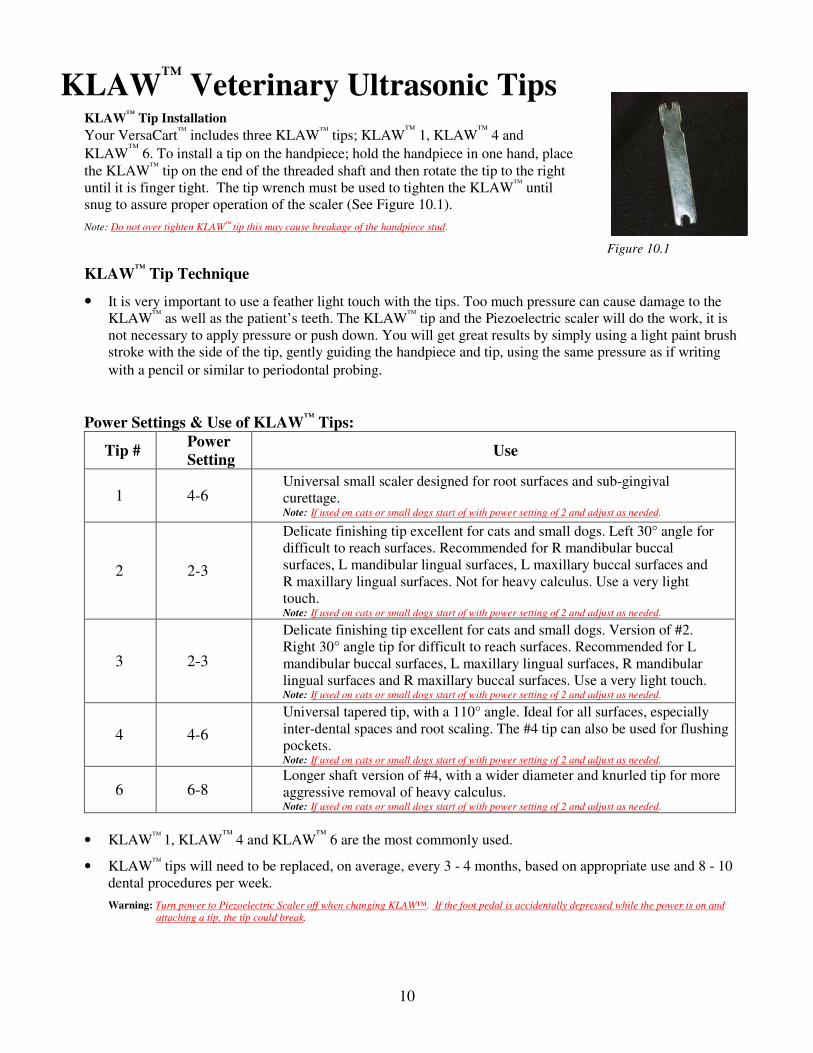
KLAW™
Veterinary Ultrasonic Tips KLAW
™ Tip Installation
Your VersaCart™
includes three KLAW™
tips; KLAW™
1, KLAW™
4 and
KLAW™
6. To install a tip on the handpiece; hold the handpiece in one hand, place
the KLAW™
tip on the end of the threaded shaft and then rotate the tip to the right
until it is finger tight. The tip wrench must be used to tighten the KLAW™
until
snug to assure proper operation of the scaler (See Figure 10.1).
Note: Do not over tighten KLAW™ tip this may cause breakage of the handpiece stud.
Figure 10.1
KLAW™
Tip Technique
• It is very important to use a feather light touch with the tips. Too much pressure can cause damage to the
KLAW™
as well as the patient’s teeth. The KLAW™
tip and the Piezoelectric scaler will do the work, it is
not necessary to apply pressure or push down. You will get great results by simply using a light paint brush
stroke with the side of the tip, gently guiding the handpiece and tip, using the same pressure as if writing
with a pencil or similar to periodontal probing.
Power Settings & Use of KLAW™
Tips:
Tip # Power
Setting Use
1 4-6 Universal small scaler designed for root surfaces and sub-gingival
curettage. Note: If used on cats or small dogs start of with power setting of 2 and adjust as needed.
2 2-3
Delicate finishing tip excellent for cats and small dogs. Left 30° angle for
difficult to reach surfaces. Recommended for R mandibular buccal
surfaces, L mandibular lingual surfaces, L maxillary buccal surfaces and
R maxillary lingual surfaces. Not for heavy calculus. Use a very light
touch. Note: If used on cats or small dogs start of with power setting of 2 and adjust as needed.
3 2-3
Delicate finishing tip excellent for cats and small dogs. Version of #2.
Right 30° angle tip for difficult to reach surfaces. Recommended for L
mandibular buccal surfaces, L maxillary lingual surfaces, R mandibular
lingual surfaces and R maxillary buccal surfaces. Use a very light touch. Note: If used on cats or small dogs start of with power setting of 2 and adjust as needed.
4 4-6
Universal tapered tip, with a 110° angle. Ideal for all surfaces, especially
inter-dental spaces and root scaling. The #4 tip can also be used for flushing
pockets. Note: If used on cats or small dogs start of with power setting of 2 and adjust as needed.
6 6-8 Longer shaft version of #4, with a wider diameter and knurled tip for more
aggressive removal of heavy calculus. Note: If used on cats or small dogs start of with power setting of 2 and adjust as needed.
• KLAW™
1, KLAW™
4 and KLAW™
6 are the most commonly used.
• KLAW™
tips will need to be replaced, on average, every 3 - 4 months, based on appropriate use and 8 - 10
dental procedures per week.
Warning: Turn power to Piezoelectric Scaler off when changing KLAW™. If the foot pedal is accidentally depressed while the power is on and
attaching a tip, the tip could break.
11
KLAW™
Tip Care & Maintenance
KLAW™
tips should be cleaned after each use. If placed in an ultrasonic or cold sterilization solution, tips
should be rinsed and dried prior to sterilization. Care should be taken to prevent the tips from touching one
another while autoclaved. Heat from the autoclave cycle can deform or break tips if they touch one another.
Autoclave the tips at a maximum of 275° F/135° C for 20 minutes in a protective package or 3 minutes
without packaging.
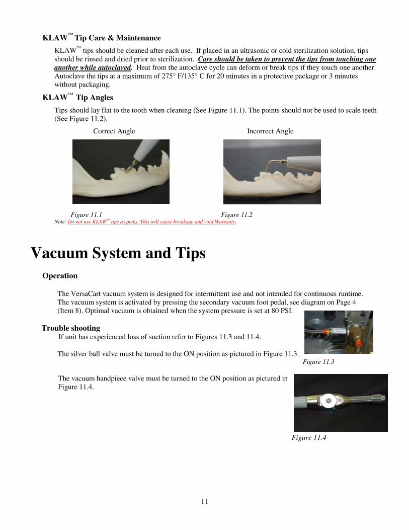
KLAW™
Tip Angles
Tips should lay flat to the tooth when cleaning (See Figure 11.1). The points should not be used to scale teeth
(See Figure 11.2).
Correct Angle Incorrect Angle
Figure 11.1 Figure 11.2
Note: Do not use KLAW™ tips as picks. This will cause breakage and void Warranty.
Vacuum System and Tips
Operation The VersaCart vacuum system is designed for intermittent use and not intended for continuous runtime.
The vacuum system is activated by pressing the secondary vacuum foot pedal, see diagram on Page 4
(Item 8). Optimal vacuum is obtained when the system pressure is set at 80 PSI.
Trouble shooting If unit has experienced loss of suction refer to Figures 11.3 and 11.4.
The silver ball valve must be turned to the ON position as pictured in Figure 11.3. Figure 11.3
The vacuum handpiece valve must be turned to the ON position as pictured in
Figure 11.4.
Figure 11.4

12
End of Day Procedure
The following list of steps will guide you through proper shut down and ensure optimum performance of your
dental unit.
1. Place a paper towel below the base of each air filter cartridge canister and then depress the small button on
the bottom of each cartridge to purge moisture from air system (See Figures 12.1 and 12.2). Inovadent
recommends changing filters annually.
Figure 12.1 Figure 12.2
2. Remove High and Low Speed Handpieces.
3. Holding handpiece in a paper towel flush air line and exhaust line with Bio Lube™
cleaner. Place four drops
of oil into the drive air line (See Figure 12.3). Reattach, then depress the foot pedal blowing air through the
handpiece for 15 to 20 seconds.
Note: High and Low Speed Handpieces should be cleaned weekly.
a. Inovadent recommends using Bio Lube™
for the
cleaning and lubricating process (See Figure 12.4).
Item # 54880
Figure 12.3 Figure 12.4
4. Purge all water from handpiece cords. Water must be purged from the High Speed Handpiece, the Air/Water
Syringe, and Piezo Handpiece daily. Switch the WATER ON to AIR PURGE (See Figure 12.5).
-Remove the High Speed Handpiece from the holder. Hold the handpiece over a sink or a bucket and depress
the foot pedal until wat0er no longer sprays from the handpiece.
-Remove Air/Water Syringe from the holder. Hold the syringe over a sink or a bucket and depress the water
button until water no longer sprays from the tip.
-Remove Piezoelectric Scaler from the holder. Depress foot pedal until water no longer sprays from the
KLAW™ tip.
Figure 12.5

13
5. Switch the water bottles switch to the OFF position (See Figure 13.1).
Figure 13.1
6. If chlorhexidine was used in one bottle, remove that water bottle, rinse and allow to dry.
Note: If using a chlorhexidine solution, the solution must be purged from the system using water.
7. Remove KLAW™
tip from Piezoelectric Handpiece, carefully clean and place in storage box.
8. Remove bur from High Speed Handpiece and replace with blank bur.
9. Store handpieces in original storage containers (High, Low and Piezoelectric).
10. Unplug cart from wall outlet if storing cart in another location or turn off power strip.
11. Wipe down cart, cords and handpieces with water and non-chloride non-iodine disinfectant.
12. Replace all handpiece cords to rack to keep cords clean and from being stepped on (See Figure 13.2).
Figure 13.2
13. Place the tank drainage hose end into small bottle and crack open drain valve slightly to expel
moisture from the tank. Close drain valve after all moisture has been expelled.
JUN-AIR® Compressor
• Review the Operation Manual before use.
• DO NOT operate the compressor if the oil level is below the minimum line on the glass bubble window.
Ideally, keep the oil level close to the maximum oil line (extra oil is included). DO NOT overfill with oil.

14
Technical Support Please contact Inovadent
™ with any questions or concerns.
INOVADENT™
200 Main Street
Elmwood, WI 54740
Toll Free: (800) 523-8185
Phone: (715) 639-2081
Fax: (715) 639-9205
E-mail: [email protected]
PREPARATIONS FOR SHIPPING:
1. Ensure the “End of Day Procedure” (located on Pages 12-13) has been completed.
2. Remove water bottles, drain and dry. Once dry, wrap in bubble wrap and place inside cabinet.
3. Remove air compressor intake filter and install small yellow plastic cap in its place.
4. Coil all handpiece cords, foot pedal cord and electrical power cable; tie together with a suitable “wire tie” and
store under the cart on top of the air storage tank.
5. Lower the cabinet to the lowest position and tighten the hand screw knob.
6. Open the air tank drain valve and drain tank of all air.
7. Ensure all accessories stored in the cabinet are packaged to prevent damage in shipping. Bubble wrap works
well inside cabinet.
15
Warranty Inovadent
TM warranties pneumatic components against defects in materials for a period of 3 years unless specified
differently. Electronic components are subject to a 1 year warranty. Labor is not covered under warranty.
- JUN-AIR® Air Compressor is covered by a manufacturer’s 2 year parts warranty. The air tank is also covered by a
manufacturer’s 5 year warranty.
- High Speed Handpiece is covered by a 1 year warranty.
- High Speed turbine is covered by a 6 month warranty.
- Low Speed Handpiece is covered by a 1 year warranty.
- Piezoelectric Handpiece is covered by a 2 year warranty.
- Warranty does not cover any product that has been subject to improper use, neglect, accident or use that is in
violation of the instructions described in the instruction manual. Merchandise returned as defective will not be
replaced until it has been determined to be defective by Inovadent™
Please allow up to 3 - 4 weeks for this process.
Products that have been repaired by someone other than an Inovadent™
technician or products that have been taken
apart by the customer are no longer covered under this warranty unless so instructed by an Inovadent™
technician.
- The customer is responsible for shipping warranty items back to Inovadent™
for evaluation. Any items found to be
faulty will be replaced by Inovadent™
, including shipping back to the customer.
- Warranty is conditional on proper use and maintenance of the unit.
- Warranty is limited to repair or replacement at manufacturer’s discretion.
- Under no circumstances will the manufacturer be held responsible for incremental or consequential damages.
- Please contact point of purchase authorized distributor for warranty repair.

APPENDIX
Installation
1. CAUTION: The bulb is a halogen-type bulb
and is susceptible to reduced lifespan from oil
(even from your hands). Use gloves if
possible to avoid touching the bulb glass.
Figure 16.1
2. Grasp H/S Fiber-Optic Cable and slide down
the outer collar to expose the adapter. Take
the bulb, noting the position of a small
insertion notch. This notch must be positioned
facing up so you can use a pointed tool to
complete the installation.
Note: This cannot be performed with a handpiece installed.
3. Insert the bulb into the adapter body as shown.
MAKE SURE TO ALIGN THE BULB PINS WITH
THE HOLES IN THE ADAPTER.
Figure 16.2
4. Using a pointed tool, seat the bulb into the
adapter (See Figure 16.3). This may take a bit
of force to start the pins into the body of the
adapter. FAILURE TO ALIGN THE PINS TO THE
HOLES WILL RESULT IN DAMAGE OF THE BULB
PINS.
Figure 16.3
5. A properly seated bulb is pictured in
Figure 16.4.
Figure 16.4
Removal
Using a pointed tool, place the tip of the tool into the
insertion notch of the bulb and push the bulb out.
16
Fiber-Optic Bulb Installation & Removal

Adding Oil to the Compressor Note: Oil level should be checked daily.
1. Remove oil plug, which is located on the top of the compressor head. Using a
22 mm wrench turn the plug counter-clockwise to loosen the plug (See Figure
17.1).
Figure 17.1
2. Add oil to the compressor through the plug opening. To prevent overfilling,
add a small amount of oil at a time (See Figure 17.2).
Figure 17.2
3. CAUTION: DO NOT overfill head with oil. Oil level should be in
between the MIN and MAX line as pictured (See Figure 17.3).
Figure 17.3
17

18
Changing Air Filters Note: Filters should be changed annually and can be ordered from any Inovadent™ distributor.
Micro-Mist Filter Item # 54916
Filter Element Item # 54915
1. Make sure all air has been drained from the dental system. Remove
the grey sediment bowl on the micro-mist filter by turning the
sediment bowl clockwise (See Figure 18.1).
Figure 18.1
2. Remove the filter from the micro-mist separator by turning the filter
clockwise. Replace the old filter by turning the new filter counter-
clockwise. Reattach the separator bowl by turning the bowl clockwise
until snug (See Figure 18.2).
Figure 18.2
3. Remove the black sediment bowl from the air pressure regulator by
turning the bowl clockwise (See Figure 18.3).
Figure 18.3
4. Remove the filter from the regulator by turning the filter clockwise.
Replace the old filter by turning the new filter counterclockwise.
Reattach the separator bowl by turning the bowl clockwise until snug
(See Figure 18.4).
Figure 18.4

19
Checking & Changing Fuses
1. Turn Power to OFF for the entire unit by unplugging the dental unit from
the wall outlet. Ensure all power has been disconnected. Open the top of
the unit and find the yellow fuse receptacle (See Figure 19.1).
Figure 19.1
2. Separate the fuse receptacle by pulling it apart. Do not pull on the yellow
wires (See Figure 19.2).
Figure 19.2
3. Check the fuse for continuity. If the fuse needs to be changed, use the
spare 1 Amp fuse provided with your unit. Fuses can be purchased
from your Inovadent™
distributor or local electronics store (See Figure
19.3).
Figure 19.3
4. Once the fuse has been replaced, push the fuse receptacle back together.
Then plug the power cord into the VersaCart™
and into the wall outlet
before testing (See Figure 19.4).
Figure 19.4

HIGH SPEED HANDPIECE 400,000 RP
WITH AUTO
In order to always provide the handpiece with clean air, water accumulated in the compressor must be drained out
DAY. DAILY LUBRICATION IS ABSOLUTELY ESSENTIAL.
OPERATION AND MAINTENANCE: Operate the handpiece at a pressure of 3
speeds of 400,000 RPM at 35 PSI. Use the brush to remove foreign particles. Particles ca
from the contra-angle head. NOTE: DO NOT attempt
blocked in the water tube.
AUTO-CHUCK (PUSH BUTTON) SYSTEM INSTRUMENT: Grasp handpiece firmly so that your thumb can touch the cap, then push on center of cap. Insert cutting
instrument into chuck until it stops, then release thumb.
button again one time (holding bur) and release. This will effect proper alignment of the jaws. For removing, grasp handpiece
firmly so that your thumb can touch the cap, and push on center of cap. Then, pull bur straight out.
OBSERVE THE FOLLOWING SAFETY RULES:
instrument after chuck is loaded to confirm the cutting instrument is held securely. Before use, verify rotating concentricit
operating the handpiece outside the mouth in a safe place. Do not use instruments which do not run concentric or produce
excessive noise.
CAUTION: Never depress the auto-chuck end cap button or rest the end cap against any part of the oral anatomy during the
handpiece operation. Depressing the end cap while bur is rotating can activate the chuck opening spring mechanism and result in
end cap heat-up and/or loss of bur retention.
REPLACEMENT OF CARTRIDGE: 1. Place bur in cartridge.
2. Unscrew head cap with head button wrench, turning counter
3. Push bur on flat surface until cartridge is removed.
4. Clean inside of handpiece head to remove moisture and foreign particles.
5. Insert new cartridge into handpiece head. When replacing with canister style cartridge, the guide projection on t
must be lined up with concave groove inside handpiece head to insure proper fit.
6. Replace head cap into handpiece by screwing clockwise with cap wrench.
NOTE: WHEN REPLACING HEAD CAP, BE CAREFUL TO ALIGN THREADS CORRECTLY. THESE THREADS
ARE VERY FINE AND CAN BE EASILY STRIPPED.
AUTOCLAVE PROCEDURE FOR HIGH SPEED HANDPIECE:
soap and water by scrubbing with a toothbrush or a 2” x 2” piece of gauze, then towel dry the handpiece. Lubricate t
Insert bur back into the handpiece and connect to unit. Run the handpiece for approximately 15
out of handpiece. Remove bur from handpiece and disconnect handpiece from unit. The handpiece is now ready for s
Follow manufacturer’s instructions for the autoclave
room temperature, then lubricate handpiece again prior to use.
IMPORTANT: LUBRICATE BY PLACING A DROP OF OIL INTO BUR HOLE TO MAINTAIN AUTO
BEST RETENTION. NEVER ALLOW OIL TO DRY OUT
CAN CAUSE MALFUNCTION.
* Never autoclave handpiece with bur in place
* Never operate handpiece without bur inserted
20
“AUTOCLAVABLE” HIGH SPEED HANDPIECE 400,000 RPM
WITH AUTO-CHUCK (PUSH BUTTON) SYSTEM
In order to always provide the handpiece with clean air, water accumulated in the compressor must be drained out
DAY. DAILY LUBRICATION IS ABSOLUTELY ESSENTIAL.
Operate the handpiece at a pressure of 35 PSI. The handpiece is engineered to attain
PSI. Use the brush to remove foreign particles. Particles can be dislodged by blowing air backward
DO NOT attempt to blow particles from the end of the handpiece, as larger particles will be
(PUSH BUTTON) SYSTEM - INSTALLING AND REMOVING ROTARY CUTTING Grasp handpiece firmly so that your thumb can touch the cap, then push on center of cap. Insert cutting
instrument into chuck until it stops, then release thumb. NOTE: After installation, it is recommended as a safety measure to push
button again one time (holding bur) and release. This will effect proper alignment of the jaws. For removing, grasp handpiece
firmly so that your thumb can touch the cap, and push on center of cap. Then, pull bur straight out.
TY RULES: Do not attempt to extend burs from the chuck. Always tug on the cutting
instrument after chuck is loaded to confirm the cutting instrument is held securely. Before use, verify rotating concentricit
a safe place. Do not use instruments which do not run concentric or produce
chuck end cap button or rest the end cap against any part of the oral anatomy during the
cap while bur is rotating can activate the chuck opening spring mechanism and result in
button wrench, turning counterclockwise.
3. Push bur on flat surface until cartridge is removed.
4. Clean inside of handpiece head to remove moisture and foreign particles.
5. Insert new cartridge into handpiece head. When replacing with canister style cartridge, the guide projection on t
must be lined up with concave groove inside handpiece head to insure proper fit.
6. Replace head cap into handpiece by screwing clockwise with cap wrench.
NOTE: WHEN REPLACING HEAD CAP, BE CAREFUL TO ALIGN THREADS CORRECTLY. THESE THREADS
ARE VERY FINE AND CAN BE EASILY STRIPPED.
AUTOCLAVE PROCEDURE FOR HIGH SPEED HANDPIECE: Remove bur from handpiece and clean handpiece with
soap and water by scrubbing with a toothbrush or a 2” x 2” piece of gauze, then towel dry the handpiece. Lubricate t
Insert bur back into the handpiece and connect to unit. Run the handpiece for approximately 15 - 20 seconds or until lubricant is
out of handpiece. Remove bur from handpiece and disconnect handpiece from unit. The handpiece is now ready for s
Follow manufacturer’s instructions for the autoclave unit being used. After autoclaving is complete, allow
piece again prior to use.
IMPORTANT: LUBRICATE BY PLACING A DROP OF OIL INTO BUR HOLE TO MAINTAIN AUTO
BEST RETENTION. NEVER ALLOW OIL TO DRY OUT IN CHUCK SPRING OR AUTO-CHUCK SPRING. THIS
* Never autoclave handpiece with bur in place.
e handpiece without bur inserted.
CHUCK (PUSH BUTTON) SYSTEM
In order to always provide the handpiece with clean air, water accumulated in the compressor must be drained out ONCE A
PSI. The handpiece is engineered to attain
n be dislodged by blowing air backward
end of the handpiece, as larger particles will be
Y CUTTING Grasp handpiece firmly so that your thumb can touch the cap, then push on center of cap. Insert cutting
After installation, it is recommended as a safety measure to push
button again one time (holding bur) and release. This will effect proper alignment of the jaws. For removing, grasp handpiece
Do not attempt to extend burs from the chuck. Always tug on the cutting
instrument after chuck is loaded to confirm the cutting instrument is held securely. Before use, verify rotating concentricity by
a safe place. Do not use instruments which do not run concentric or produce
chuck end cap button or rest the end cap against any part of the oral anatomy during the
cap while bur is rotating can activate the chuck opening spring mechanism and result in
5. Insert new cartridge into handpiece head. When replacing with canister style cartridge, the guide projection on the canister
NOTE: WHEN REPLACING HEAD CAP, BE CAREFUL TO ALIGN THREADS CORRECTLY. THESE THREADS
Remove bur from handpiece and clean handpiece with
soap and water by scrubbing with a toothbrush or a 2” x 2” piece of gauze, then towel dry the handpiece. Lubricate the handpiece.
20 seconds or until lubricant is
out of handpiece. Remove bur from handpiece and disconnect handpiece from unit. The handpiece is now ready for sterilization.
unit being used. After autoclaving is complete, allow handpiece to return to
IMPORTANT: LUBRICATE BY PLACING A DROP OF OIL INTO BUR HOLE TO MAINTAIN AUTO-CHUCK
CHUCK SPRING. THIS

This product is designed for veterinary dental use. O
professional.
1. Bur Change: The bur-locking position occurs when the bla
above the black dot on the position ring. To open the chuck for a bur change
2. Operation: Recommended operating pressure: 25
MAINTENANCE: To keep the Low Speed Handpiece in
Bio Lube™. Lubrication should be performed daily after cleaning the unit.
1. Lubrication Be sure to lubricate after autoclaving or in the event
back of Low Speed Handpiece. Reattach the handpiece to the unit and run the handpiece for 8 to 10 seconds.
* Hold handpiece firmly. Dropping the handpiece
2. Surface Cleaning Clean with brush and wipe off by cloth. Lubricat
cause damage.
3. Inside Cleaning Spray Bio Lube™ cleaner into the drive-air hole
handpiece for 2 to 3 seconds to expel built up debris from handpiece. After handpiece has been cleaned make sure handpi
lubricated by following the lubrication procedure
STERILIZATION: Do not put handpiece through ultrasonic disinfection solution cleaning procedure. Do not use cold sterilization or dry heat
1. Clean with brush and wipe off with cloth.
2. Lubricate.
3. Autoclave at 130 - 135 ْC (2Mpa) for 20 minutes
4. Take the Low Speed Handpiece out of the autoclave and dry at
higher than 135 ْC.
5. After the Low Speed Handpiece is completely dried, lubricate it twice.
6. Open and close chuck. Repeat twice.
WARNING: 1. Do not drop Low Speed Handpiece or apply excessive force or impact on
bur on Low Speed Handpiece from hitting others during
2. When water gets inside the handpiece, lubricate
3. Do not run handpiece without locking the bur.
4. Do not run handpiece with chuck opened.
5. For safety, mount test the bur (the standard accessory) on the Low Speed H
6. In using the bur with its working diameter more than 5 mm
** In high speed use, the bur with large operating diameter could
WARRANTY: Low Speed Handpiece 1 year.
21
Low Speed Handpiece
for veterinary dental use. Operation and maintenance should be performed under the supervision of a veterinary
occurs when the black dot on the locking ring is adjusted to a position in which it is located directly
pen the chuck for a bur change, twist the chuck until the black dot is located above the red dot
commended operating pressure: 25 PSI (Maximum air pressure: 50 PSI).
andpiece in good condition, only use dental handpiece oil. Inovadent
Lubrication should be performed daily after cleaning the unit.
the event that water and/or dust gets inside. Place 4 drops of lubricant
Reattach the handpiece to the unit and run the handpiece for 8 to 10 seconds.
ping the handpiece may cause damage.
Clean with brush and wipe off by cloth. Lubricate after surface cleaning. Do not submerge the handpiece in water to
air hole. Reattach the handpiece to the unit. While holding the handpiece in a paper towel run
handpiece for 2 to 3 seconds to expel built up debris from handpiece. After handpiece has been cleaned make sure handpi
lubricated by following the lubrication procedure.
rough ultrasonic disinfection solution cleaning procedure. Do not use cold sterilization or dry heat
utes.
e autoclave and dry at room temperature. Do not operate autoclave dry cycle at a
andpiece is completely dried, lubricate it twice.
or apply excessive force or impact on to the connected bur. This will void the W
hers during autoclave).
e handpiece, lubricate three times.
not run handpiece without locking the bur.
(the standard accessory) on the Low Speed Handpiece, when it is not in use.
In using the bur with its working diameter more than 5 mm, gradually increase the speed in order to assure positive retention.
** In high speed use, the bur with large operating diameter could disconnect and cause serious damage to the patient or user
n and maintenance should be performed under the supervision of a veterinary dental
tion in which it is located directly
twist the chuck until the black dot is located above the red dot.
good condition, only use dental handpiece oil. Inovadent™ recommends using
Place 4 drops of lubricant oil in the drive-air at the
in water to clean as this will
handpiece in a paper towel run
handpiece for 2 to 3 seconds to expel built up debris from handpiece. After handpiece has been cleaned make sure handpiece is also
rough ultrasonic disinfection solution cleaning procedure. Do not use cold sterilization or dry heat.
m temperature. Do not operate autoclave dry cycle at a temperature
This will void the Warranty. (Prevent the
, gradually increase the speed in order to assure positive retention.
use serious damage to the patient or user.
22
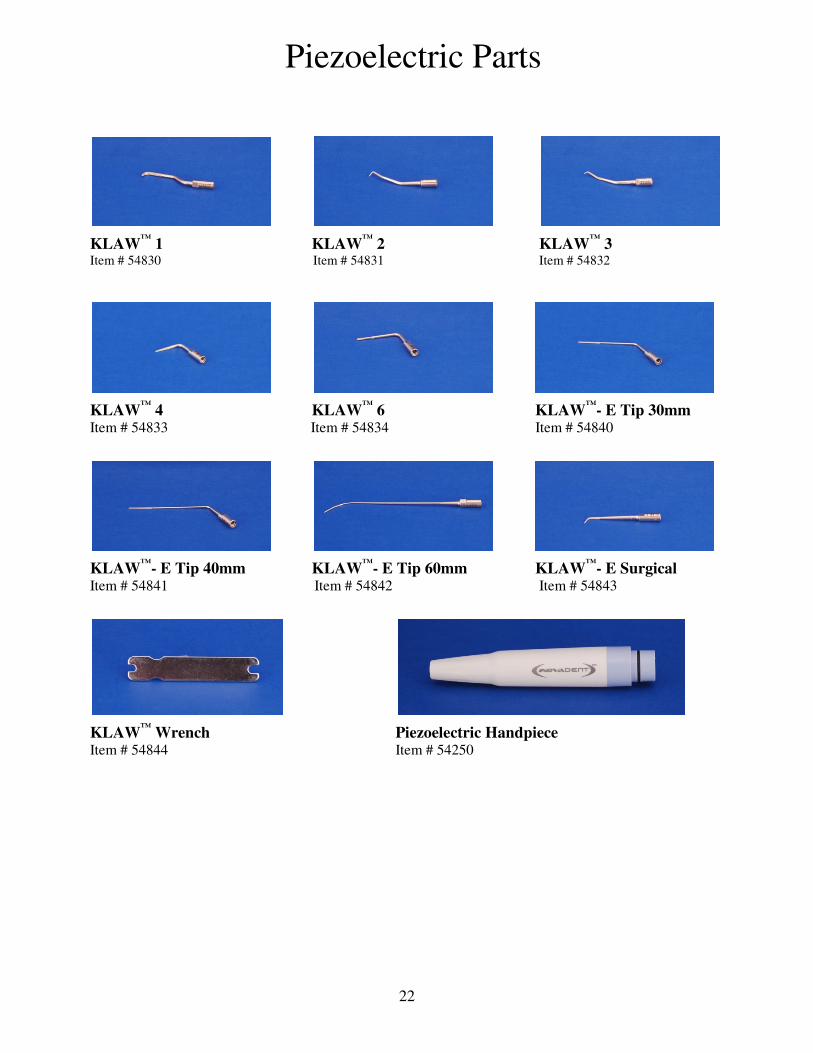
Piezoelectric Parts
KLAW™
1 KLAW™
2 KLAW™
3 Item # 54830 Item # 54831 Item # 54832
KLAW™
4 KLAW™
6 KLAW™
- E Tip 30mm Item # 54833 Item # 54834 Item # 54840
KLAW™
- E Tip 40mm KLAW™
- E Tip 60mm KLAW™
- E Surgical Item # 54841 Item # 54842 Item # 54843
KLAW™
Wrench Piezoelectric Handpiece Item # 54844 Item # 54250

23
Handpiece Parts
High Speed Handpiece with Fiber-Optics High Speed Handpiece Non Fiber-Optic Item # 54900 Item # 54901
Fiber-Optic Light Bulb 4-Hole Gasket 5-Hole Gasket Item # 54905 Item # 54911 Item # 54910
High Speed Turbine End Cap for H/S Handpiece Item # 54903 Item # 54907
Prophy Angle Prophy Paste, Fine Grit Item # 54825 Qty 10 Item # 54828 Qty 25
Low Speed Handpiece
Item # 54902

24
Burs
#2 Round Bur #701L Carbide Bur #330 Pear Shaped Bur Item # 54821 Item # 54803 Item # 54820
Standard Length Standard Length Standard Length
Item # 54822 Item # 54805
Surgical Length Surgical Length
#699 Carbide Bur #700 Carbide Bur #702L Carbide Bur Item # 54810 Item # 54811 Item # 54812
Standard Length Standard Length Surgical Length
#701 Carbide Bur Item # 54802
Standard Length

25
Replacement Parts
Water Bottle Gasket Regulator Filter Micro-mist Filter Item # 54912 Item # 54915 Item # 54916
JUN AIR Compressor Oil Water Bottle, 1 Liter Ultra Scale Item # 54884 Item # 54925 Item # 54270
Manual Number 20-255-0012