version: 1.07.00 copyright © 2012, videoray llc - the...
TRANSCRIPT

Version: 1.07.00
Copyright © 2012, VideoRay LLC - The Global Leader in Micro-ROV Technology
1

Copyright Notice
This material is copyright protected. No material may be reproduced or transmitted in any form or by any meansfor any purpose without expressed written consent of VideoRay LLC.
Copyright © 2012, VideoRay LLC - The Global Leader in Micro-ROV Technology
2

Table of Contents
Introduction About this Documentation . . . . . . . . . 8
Glossary . . . . . . . . . 10
General FAQ . . . . . . . . . 15
Pro 4 Overview . . . . . . . . . 17
Quick Start Instructions . . . . . . . . . 18
Safety First . . . . . . . . . 19
System Components . . . . . . . . . 20
Pre-Dive Preparations . . . . . . . . . 21
Dive Operations . . . . . . . . . 25
Post-Dive Operations . . . . . . . . . 26
Equipment Guide . . . . . . . . . 27 ROV . . . . . . . . . 28
ROV Connections . . . . . . . . . 29
Buoyancy . . . . . . . . . 30
Propulsion . . . . . . . . . 31
Main Camera . . . . . . . . . 32
Main Lights . . . . . . . . . 33
Sensors . . . . . . . . . 34
Control Panel . . . . . . . . . 35
Safety Circuits . . . . . . . . . 36
Switches and Connections . . . . . . . . . 37
Computer . . . . . . . . . 40
Panasonic Toughbook . . . . . . . . . 41
Dell 4500/4600 . . . . . . . . . 42
Monitor . . . . . . . . . 43
Hand Controller . . . . . . . . . 44
Help . . . . . . . . . 46
Joystick . . . . . . . . . 47
Depth Control . . . . . . . . . 48
Camera Switch . . . . . . . . . 49
Camera Tilt . . . . . . . . . 50
Camera Focus . . . . . . . . . 51
Lights . . . . . . . . . 52
Snapshot . . . . . . . . . 53
Record . . . . . . . . . 54
Manipulator/Cutter . . . . . . . . . 55
Lateral Thruster . . . . . . . . . 56
Tether . . . . . . . . . 57
TDS . . . . . . . . . 59
Connections Summary . . . . . . . . . 61
Accessories . . . . . . . . . 62
BlueView Technologies . . . . . . . . . 63
3

Buckley's . . . . . . . . . 65
Cygnus Instruments . . . . . . . . . 66
Desert Star Systems . . . . . . . . . 67
Franatech . . . . . . . . . 68
KCF Technologies . . . . . . . . . 69
Lyyn . . . . . . . . . 70
Tritech International . . . . . . . . . 71
Turner Designs . . . . . . . . . 73
YSI . . . . . . . . . 74
VideoRay . . . . . . . . . 75
Included Accessories . . . . . . . . . 76
Optional Accessories . . . . . . . . . 77
Manipulator . . . . . . . . . 78
Cutter . . . . . . . . . 79
Hull Inspection Stabilizer . . . . . . . . . 80
Lateral Thruster . . . . . . . . . 81
Laser Scaling Device . . . . . . . . . 82
Radiation Sensor . . . . . . . . . 83
External Camera . . . . . . . . . 84
HD Camera . . . . . . . . . 85
PAM . . . . . . . . . 86
TINA . . . . . . . . . 87
Miscellaneous . . . . . . . . . 88
VideoRay Cockpit Guide . . . . . . . . . 89 Video Window . . . . . . . . . 90
Video Text Overlay . . . . . . . . . 92
Instruments . . . . . . . . . 94
ROV Health . . . . . . . . . 96
Control Sensitivity . . . . . . . . . 97
Compass . . . . . . . . . 99
Depth . . . . . . . . . 100
Camera and Lights . . . . . . . . . 101
Camera Menu . . . . . . . . . 102
Default Settings . . . . . . . . . 104
Lens . . . . . . . . . 107
Exposure . . . . . . . . . 108
White Balance . . . . . . . . . 110
Wide Dynamic Range . . . . . . . . . 111
Day & Night . . . . . . . . . 113
Image . . . . . . . . . 114
Special . . . . . . . . . 115
Camera Title . . . . . . . . . 116
Communication Adjust . . . . . . . . . 117
Privacy . . . . . . . . . 118
Position . . . . . . . . . 119
Motion Detection . . . . . . . . . 120
Display . . . . . . . . . 121
Factory Default . . . . . . . . . 122
Exit . . . . . . . . . 123
4

Water Temperature . . . . . . . . . 124
Turns Indicator . . . . . . . . . 125
Accessory Instruments . . . . . . . . . 126
Manipulator/Cutter . . . . . . . . . 127
Lateral Thruster . . . . . . . . . 128
Laser Scaling Device . . . . . . . . . 129
External Camera . . . . . . . . . 130
LYYN Controls . . . . . . . . . 131
PAM . . . . . . . . . 132
Control Bar . . . . . . . . . 133
Close . . . . . . . . . 134
Help . . . . . . . . . 135
Service Bay . . . . . . . . . 136
Pre-Dive Checklist . . . . . . . . . 138
Post-Dive Checklist . . . . . . . . . 139
Scheduled Maintenance . . . . . . . . . 140
Communications Status . . . . . . . . . 141
Engine Room . . . . . . . . . 142
Status Information . . . . . . . . . 143
Systems Tuning . . . . . . . . . 144
Compass Calibration . . . . . . . . . 147
Images and Videos . . . . . . . . . 148
User Settings . . . . . . . . . 149
Instrument Settings . . . . . . . . . 150
System Settings . . . . . . . . . 152
Depth Sensor . . . . . . . . . 153
Advanced Depth Settings . . . . . . . . . 154
Compass . . . . . . . . . 155
System of Measure . . . . . . . . . 157
Video Capture and Display . . . . . . . . . 158
Video Capture Settings . . . . . . . . . 159
Advanced Video Settings . . . . . . . . . 160
Data Import . . . . . . . . . 161
Data Export . . . . . . . . . 163
Companion Applications . . . . . . . . . 166
Instrument Display . . . . . . . . . 167
Software Management . . . . . . . . . 168
Software Installation . . . . . . . . . 169
Software Updates . . . . . . . . . 170
Folder Structure . . . . . . . . . 173
Application Integration . . . . . . . . . 174
Operations Guide . . . . . . . . . 176 Project Management . . . . . . . . . 177
Mission Planning . . . . . . . . . 178
General Logistics . . . . . . . . . 179
On-site Operations . . . . . . . . . 180
Project Completion . . . . . . . . . 181
Tether Management . . . . . . . . . 182
Piloting . . . . . . . . . 183
5

Auto Depth . . . . . . . . . 184
Auto Heading . . . . . . . . . 186
Low Visibility . . . . . . . . . 187
Swift Current . . . . . . . . . 189
Deep Water . . . . . . . . . 190
Images and Videos . . . . . . . . . 191
Still Images . . . . . . . . . 192
Video Recording . . . . . . . . . 193
Video Editing . . . . . . . . . 194
Video Production . . . . . . . . . 195
Maintenance Guide . . . . . . . . . 196 Best Practices . . . . . . . . . 197
Emergency Situations . . . . . . . . . 198
Routine Maintenance . . . . . . . . . 199
Propellers . . . . . . . . . 201
Cartridge Seals . . . . . . . . . 202
Example Cartridge Seals . . . . . . . . . 203
Light Domes or Modules . . . . . . . . . 204
Camera Domes . . . . . . . . . 205
Diagnostics and Repair . . . . . . . . . 206
Power . . . . . . . . . 207
Communications . . . . . . . . . 208
Control . . . . . . . . . 209
Video . . . . . . . . . 210
Accessories Guide . . . . . . . . . 212 Integration Overview . . . . . . . . . 213
Categories . . . . . . . . . 215
Imagery . . . . . . . . . 217
LYYN Hawk . . . . . . . . . 218
External Camera . . . . . . . . . 219
HD Camera . . . . . . . . . 220
Intervention . . . . . . . . . 221
Manipulator . . . . . . . . . 222
Cutter . . . . . . . . . 223
Propulsion . . . . . . . . . 224
Hull Inspection Stabilizer . . . . . . . . . 225
Lateral Thruster . . . . . . . . . 226
Sonar . . . . . . . . . 227
ProViewer . . . . . . . . . 228
Pole Mount . . . . . . . . . 229
Gemini . . . . . . . . . 230
SeaSprite . . . . . . . . . 231
Position Tracking . . . . . . . . . 232
Pilot . . . . . . . . . 233
AquaMap Seafloor . . . . . . . . . 234
AquaMap Shiphull . . . . . . . . . 235
Smart Tether . . . . . . . . . 236
Micron Nav . . . . . . . . . 237
Micron Echosounder . . . . . . . . . 238
6

Sensors . . . . . . . . . 239
Cathodic Protection Probe . . . . . . . . . 240
C3 Fluorometer . . . . . . . . . 241
Laser Scaling Device . . . . . . . . . 242
METS Methane Sensor . . . . . . . . . 243
Radiation Sensor . . . . . . . . . 244
Thickness Gauge . . . . . . . . . 245
600XL Sonde . . . . . . . . . 246
Integration . . . . . . . . . 247
PAM . . . . . . . . . 248
TINA . . . . . . . . . 249
Customization Guide . . . . . . . . . 250 This Documentation . . . . . . . . . 251
Checklists . . . . . . . . . 253
Hand Controller . . . . . . . . . 254
Accessories . . . . . . . . . 255
SDK . . . . . . . . . 256
Override Mode . . . . . . . . . 257
Upgrader's Guide . . . . . . . . . 258 What's New . . . . . . . . . 259
Pro 3 Upgrader's Guide . . . . . . . . . 260
System Architecture . . . . . . . . . 262
Feature Updates . . . . . . . . . 265
Compatibility Issues . . . . . . . . . 268
7

About this Documentation
The VideoRay Pro 4 has sophisticated features, but is easy to use and maintain once you learn its capabilitiesand the proper operating techniques. This documentation will guide you through your first dive and provideadditional details to help you learn all aspects of its operation.
Document Organization
This documentation is organized into several guides.
The Quick Start Instructions in this section provide the basic steps to get you operational as quickly aspossible while keeping you and the equipment safe.
The Equipment Guide provides details about each component and its function.
The VideoRay Cockpit Guide explains the software features and operation in detail.
The Operations Guide provides tips on how to use the system most effectively.
The Maintenance Guide provides procedures for routine maintenance, diagnostics and repair.
The Accessories Guide provides information about using accessories with VideoRay.
The Customization Guide provides information about customizing the system to better meet yourspecific needs.
The Upgrader's Guide provides information about the latest improvements and comparative informationfor people who are familiar with the VideoRay Pro 3.
Document Navigation
You can navigate through the documentation to specific topics using the menu, or step through sequentially usingthe Next, Previous and Up tabs. The Next tab will step you from the current topic to the next topic at the samelevel unless the current topic has a sub-topic. If the current topic has a sub-topic, the Next tab will step you to thefirst sub-topic. The Previous tab works similarly, but in reverse sequence. The Up tab can be used to move froma sub-topic to its parent topic. Additionally, your current location within the document is shown at the top of eachpage under the external links. You can click on any level of the hierarchy to go that location.
Inline links are shown in blue bold font.
A PDF version of this document is available for viewing the entire document as a single file or for printing. Afree PDF Reader is available from Adobe.
Document Conventions
Several symbols are used throughout this documentation to add emphasis and to assist in relocating importantinformation. The following table describes these symbols and their uses.
Symbol Description
The Danger icon is used to indicate there is a potential risk of personal injury or death. Extracare should be taken to understand the risks, and all personnel should exercise caution. It mayalso be appropriate to warn others in the immediate vicinity.
The Caution icon is used to indicate there is a potential risk of damage to the equipment orsurrounding property. Personnel should receive training in the appropriate procedures beforeattempting to operate or maintain the equipment.
The Note icon is used to emphasize a specific detail or point of information.
8

The Tip icon is used to highlight a suggestion.
The Hand icon is used to indicate an interactive element of the page. When you hover yourmouse over the hand icon, an image on the page will change to reflect the information in thetext immediately prior to the hand icon. Try it here - hover your mouse over the following text
and hand icon to turn the hand icon to the left blue: Interactive Text .
Document Customization - My_Notes
This document has been developed to allow local online versions to be customized using the My_Notesfeature. Users can add their own notes to each page. See the Customizing this Documentation page in theCustomization section for more information about how to customize this document.
Quality Commitment
VideoRay strives to design, manufacture and deliver the highest quality products and services, including thisdocumentation. We have made every effort to ensure that this documentation is accurate and provides you withthe most effective means to learn how to use your new Pro 4. However, there is no substitute for experienceand/or training, especially with respect to the real purpose for which you plan to use this equipment. Weencourage you to explore options beyond the scope of these materials to expand your knowledge and skillsnecessary to support your application. In addition to this documentation, VideoRay offers training and technicalsupport and hosts a general user discussion forum and user image gallery.
We also realize that collectively, users of our products spend considerably more time operating our systems thanwe do ourselves. Users also encounter more diverse operating environments across an extremely broad rangeof applications. We highly value this vast experience base, and if you have any questions or suggestions, pleasefeel free to contact us by any of the following methods.
Address
VideoRay LLC580 Wall StreetPhoenixville, PA 19460USA
[email protected] General Information and Sales
Technical Support
Telephone
+1 610-458-3000 Office
+1 610-458-3010 Fax
The information contained herein is deemed accurate at the time of printing and is subject to change withoutnotice.
9

Glossary
Accelerometer - A device used to measure acceleration - used to determine pitch and roll of the ROV
Accessory - An optional device that can be used with the VideoRay system to augment its features andcapabilities
Accessory Port - ROV connection for ROV mounted accessories that provides access to power and datacircuits
Acoustic - Using sound as a method of communicating underwater - often used to measure distance
AGC - See Automatic Gain Control
Altitude - The height of the ROV off of the bottom
Analog Video Out - Video connector on the control panel for interfacing composite analog displays
APIC - (Auxiliary Pair of Independent Conductors) Also called the Spare Pair (See AUX, AUX Port and SparePair)
Artificial Horizon - See Attitude Indicator
Attitude Indicator - Instrument that provides an indication of the pitch and roll of the ROV
ATW - (Automatic White Balance) color corrects an image - See also White Balance
Audio - In VideoRay context, the ability to record verbal annotation along with the video recording
Auto Depth - Control Feature that maintains the depth of the ROV at a constant value
Auto Heading - Control Feature that maintains the heading (compass direction) of the ROV at a constant value
Automatic Gain Control - Used to manage the intensity of the image - can be adjusted for lighter or darkerimages
AUX - Circuit provided for accessories or custom applications (See APIC)
AUX Port - Connector on the control panel that provides access to the AUX circuit (See APIC)
Back Light Compensation - Intentional overexposure to minimize the effects of a bright area in an image
Ballast - Weights used to decrease buoyancy of the ROV to achieve desired buoyancy
Black and White - Image quality using black white or shades of gray only
BLC - See Back Light Compensation
Buoyancy - The tendency to float, sink or remain at a constant depth
Bypass - The Bypass switch allows the system to be used in the event of a Line Insulation Monitor alarm state(See LIM)
Camera - The camera provides a video image from the ROV
Camera Focus - Method to control image focus or the current state of image focus
Camera Menu - Method to control camera functions
Camera Switch - Method to select whether the internal or external camera is active
Camera Tilt - Method to control the vertical angle of the camera or the current state of camera tilt
10

Cartridge Seal - Component used to lubricate the thruster shaft and seal it from water intrusion
Celsius - Unit of measure of temperature
Checklist - Method to ensure all operations are completed as planned or functions perform as expected
Close - The Close button exits VideoRay Cockpit
Color - Image quality that uses all colors
Compass - Instrument that provides an indication of the heading of the ROV
Compatibility - The state or being able to work together
Computer - Primary topside component required to run VideoRay Cockpit
Control Bar - A VideoRay Cockpit feature that provides access to several functional areas of the software
Control Panel - The surface component that provides power and communications with the ROV
Control Sensitivity - The ability to change the responsiveness of the ROV to the amount of joystick input
Current - The flow of water or electricity
Customization - The ability to change the operation or behavior of the system to make it more suitable forspecific applications
Cutter - An optional ROV mounted device for cutting objects
Data Export - Allows data from the ROV to be exported to external applications
Data Import - Allows data from external applications or sensors to be displayed on the video as overlay text
Date - Calendar Date
DB-15 - Connector style with 15 contacts commonly used for VGA connections
DB-9 - Connector style with 9 contacts commonly used for serial data connections
Deinterlace - Display a video image as two successive scans of alternate rows of the image
Depth - Vertical location of the ROV within the water measured from the surface
Depth Control Knob - Method of controlling the depth of the ROV
Depth Gauge - Display that indicates the current depth of the ROV
Depth Rating - Maximum depth for operation of the ROV
Diagnostics - Method for identifying the cause of a problem
Digital Slow Shutter - Camera feature to improve image in low light situations
Edit - The process of modifying data
ELC - Lens type setting required for optimal image from the VideoRay Pro 4 camera
Engine Room - VideoRay Cockpit interface to access advanced status information and settings
Ethernet - Data Protocol and connector style
Exit - Close the camera menu or VideoRay Cockpit
Export - Method to communicate data from the ROV to other systems
Exposure - Method to control the amount of light captured by the camera
Factory Default - Initial state of a variety of parameters
11

Fahrenheit - Unit of measure of temperature
Fault - Indication of a problem
Feet - Unit of measure of length or distance
Fine - Low power control mode
Firmware - Software that resides on the ROV
Float Block - Required ROV component used to increase buoyancy of the ROV - counteracted by ballast toachieve desired buoyancy
Gain - Setting to control the level of some parameter
Generator - AC power source that typically runs on gasoline or diesel fuel
GFCI - (Ground Fault Circuit Interrupter) A safety circuit
GPS - (Geographic Positioning System) Device that provides location
Hand Controller - Input device to control the ROV's operation
Heading - The compass direction the ROV is facing
Help - Information intended to provide assistance
Hull Inspection Stabilizer - External device designed to help stabilize the ROV while inspecting ships' hulls
Humidity - Qualitative measure of the amount of moisture in the air
IEC - (International Electrotechnical Commission) Power cord connector standard
Import - Method to receive and process data from other systems
Instrument - VideoRay Cockpit interface feature to display information or control features
Instrument Display - The ability to set an instrument's opacity or turn it on or off
Inverter - AC power source that runs on battery
Joystick - Input device for controlling the surge and yaw of the ROV
Lens - Camera element used to capture and focus light to create an image
Lights - ROV component that provides lights for scene illumination in dark areas
Light Dome - Protective covering over the lights
LIM - (Line Insulation Monitor) A safety circuit
Main Dome - Protective covering over the camera
Manipulator - An optional ROV mounted device for grabbing objects
Meter - Unit of measure of length or distance
Mission Planning - A method to prepare for a successful ROV operation
Monitor - Device used for the display of the video or computer image
Mute - The ability to silence the audio recording
My_Note - Feature of the documentation that allows users to add personal notes to the online pages
Negative - A state of buoyancy in which the ROV will sink and a type of tether
Neutral - A state of buoyancy in which the ROV will maintain it's vertical location and a type of tether
12

O-Ring - Sealing device
Opaque - Unable to see through
Overlay - Text or logo superimposed on the video
PAM - (Protocol Adapter Multiplexer) A programmable interface device
Pitch - The nose-up or nose-down attitude or motion of the ROV
Positive - A state of buoyancy in which the ROV will float and a type of tether
PPT - (Professional Performance Tether) A type of tether
Pressure Sensor - A device to measure pressure - used to calculate ROV depth
Propeller - ROV component with pitched blades that generate thrust when rotated
RCA - Connector style commonly used for composite analog video
Record - Command to initiate video capture to a storage media
Remotely Operated Vehicle - The underwater vehicle
RJ-45 - A connector Style with 8 contacts commonly used for Ethernet connections
Roll - The left or right leaning attitude or motion of the ROV
ROV - See Remotely Operated Vehicle
ROV Health - An instrument that provides feedback on the status of several critical ROV systems
RS-485 - Data Protocol
Safety - State of, or application of, safe practices
SDK - (Software Developer's Kit) A program and a set of software libraries and utilities to aid custom programdevelopment
Sensitivity - The amount of output based on a specific level of input, particularly for the joystick
Sensor - An instrument for measuring a specific property of an object or the environment
Service Bay - VideoRay Cockpit interface that provides diagnostic information and checklists
Settings - The values of specific controls or parameters, or the ability to manage these
Skid - The base of the ROV and often used to mount accessories
Software Developer's Kit - See SDK
Snapshot - A still image captured from the video image
Spare Pair - Extra pair of conductors in the tether - See also APIC
Strain Relief - An ROV and tether component that reduces the load on tether connections
Sun Shade - Device used to shade the display for better visibility in direct sunlight
Surge - The forward and backward motion of the ROV
TDS - (Tether Deployment System) A reel for storing tether
Temperature - Qualitative measure of hot or cold
Termination Block - ROV component that connects the ROV to the tether
Tether - The cable that connects the ROV to the control panel
13

Tether Deployment System - See TDS
Text Overlay - Ability to superimpose text over a video image
Third Axis - Rotational motion of the joystick - can be used as an alternate control method of the joystick
Thruster - ROV propulsion system including a motor and propeller
Thruster Cartridge Seal - Seals the thruster shaft from water intrusion
Thruster Nozzle - Shroud around the propeller
Tilt Arm - Control panel component to adjust the angle of the optional second monitor
TINA - (Tether Interface Node Adapter) A device that allows accessories to be connected directly to the tetherwithout the ROV
Transparent - Ability to see through
Turbo - High power control mode
Turns Indicator - An instrument that keeps track of the number of rotations of the ROV about its vertical axisand provides information on which direction to turn to unwind the tether
Umbilical - See also Tether
Upgrade - A newer version or the process of installing a newer version
USB - (Universal Serial Bus) Data protocol and connector style
User Settings - VideoRay Cockpit interface to access operating parameters
VGA - Video Graphics Array) Video format and connector style
Video - In VideoRay context, the image from the ROV's camera or the ability to record this image
Video Encoder - Defines a method of storing a video image within a file format
Video Window - Display component that displays the video image from the camera
VideoRay Cockpit - VideoRay ROV control program
VideoRay Data Folder - Destination folder for video recordings and snapshots
VideoRay Update - Software program to upload new firmware to the ROV
Virtual COM Port - A software feature that allows two applications on the same computer to communicatewithout requiring physical ports
Visibility - Measure of the clarity of water
WDR - See Wide Dynamic Range
Whip - A short length of tether attached to the ROV or control panel
White Balance - Camera feature to color correct images from the camera
Wide Dynamic Range - Camera feature to improve image in high contrast lighting situations
Yaw - The left or right turning attitude or motion of the ROV
Zoom - Camera image magnification
14

FAQ (Frequently Asked Questions)
New users typically have some pretty basic questions about the Pro 4. Before getting to the details, this sectionis provided to address the questions asked most frequently, without having to scan through the manual to find theanswers. Additional questions and answers are available online at www.rovfaq.com, which is also linked at thetop of this page.
How hard is it to learn how to operate the Pro 4?
The Pro 4 is easy to learn to operate. In a few hours, user should be able to pilot the ROV confidently inclear, calm water and know enough about it to maintain it in good condition for years. However, masteringall the knowledge and developing the skills to be able to pilot the ROV in much more demandingsituations with near zero visibility and swift current will require more experience. See the Quick StartInstructions for more information.
1.
How deep can the Pro 4 go?
The rated depth of the Pro 4 is 300 meters (1000 feet).
2.
How fast can the Pro 4 go?
The rated speed of the Pro 4 is 4.2 knots.
3.
In how much current can the Pro 4 operate?
While the logical answer seems to be that it can not operate in current faster than the vehicle can go incalm water, operational tactics can be used to operate in current that exceeds the maximum speed of theROV. See the Piloting in Current section of the Operations Guide for more information.
4.
How much can you pick up with the Pro 4?
The Pro 4 manipulator closes with about 4.5 kilograms (10 pounds) of force, and the vehicle has limitedvertical thrust. However, if you can grab a secure hold of an object, you can retrieve it by pulling on thetether. Items weighing up to 20 kilograms (80 pounds) in water have been successfully retrieved. See theTether section in the Equipment Guide for more information.
5.
How much tether can you use with the Pro 4?
The maximum tether length is about 600 meters (2000 feet). Tether is like conventional electric extensioncords and multiple sections can be plugged in together. See the Tether section in the Equipment Guidefor more information.
6.
How do you adjust the buoyancy and trim of the Pro 4?
The buoyancy and trim can be adjusted by opening the skid pod and adding or removing the brass ballastweights. See the Pre-Dive Preparations section of the Quick Start Instructions for more information.
7.
Can you record pictures and video from the Pro 4?
Pictures and videos can be recorded in digital format on the computer. There is also an analog outconnector for recording to standard analog devices that accept a composite video signal. See theImages and Videos section in the Operations Guide for more information.
8.
Can you record topside audio for narration?
Topside audio can be recorded along with the video file. Audio can be muted while recording to eliminate
9.
15

background noise. See the Video Window section in the VideoRay Cockpit Guide for moreinformation.
Can you import data from other systems?
Data from sensors or other systems can be imported into VideoRay Cockpit and displayed on the videoas overlay test. See the Data Import section in the VideoRay Cockpit Guide for more information.
10.
Can you export data from the Pro 4?
Data from the VideoRay Pro 4 sensors can be exported to other systems via a COM port in real time or afile for post processing. See the Data Export section in the VideoRay Cockpit Guide for moreinformation.
11.
How much maintenance is required for the Pro 4?
The Pro 4 is easy to maintain. There are very few consumable parts, and these have been designed to beas easy to replace as possible. Cleaning the vehicle after each use is one of the most importantmaintenance requirements. See the Routine Maintenance section of the Maintenance Guide for moreinformation.
12.
16

VideoRay Pro 4 Overview
VideoRay is pleased to present the latest model in its top-of-the line professional series Micro-ROVs - theVideoRay Pro 4. Like the Pro 3, the Pro 4 was designed for performance and maintainability, but has entirely newinternal electronics, including camera, LED lights, processor, and added sensors. With powerful brushlessmotors, the Pro 4 further extends VideoRay's position as the fastest and most powerful tether pulling vehicle.Additional improvements include deeper depth rating, hydrodynamic streamlining, and optimized ballastadjustment. Topside control is based on industry standard rugged computers, with new software that integratesseveral functions while dynamically reconfiguring for ease of use.
The Pro 4 submersible builds on VideoRay's strengths with more than twice the vertical thrust of the Pro 3, and50% greater horizontal thrust. A depth rating of 300 meters (1000 feet) is standard. Improvements in theelectronics allow for both greater total tether length up to 600 meters (2000 feet) and much better powertransmission over longer tethers. Existing VideoRay tethers can be used with the Pro 4 - and different tethertypes can still be combined to meet different operational requirements. New sensors, including 3 axes compassand accelerometers and MEMS gyro improve navigational capabilities. The primary video camera features ultralow light and Wide Dynamic Range imaging capability, with a wide range of user controllable parameters fordemanding imaging situations. Coupled with the very high intensity LED lighting, the images and video that canbe captured are far clearer, particularly in difficult lighting conditions. A second camera can be rotated 270degrees to provide lateral views as needed.
The topside control configuration replaces inflexible and limited switches and knobs with context-sensitivecontrols that go beyond simply controlling the submersible to controlling navigation, sonar, image and videocapture, and other sensors and accessories in addition to the submersible. This "systems approach" significantlyreduces operator workload and distraction caused by separate systems for sonar, navigation, video capture, andvehicle control.
The Pro 4 is part of an industry-wide initiative led by VideoRay (the largest volume ROV manufacturer in theworld) to go beyond separate "point" technology solutions to a "systems" approach to solving underwater tasks.The Pro 4 series ROVs are packaged in configurations such as the PS (Port Security Configuration) and CD(Commercial Dive Configuration) designed to solve a specific or series of underwater tasks, with VideoRayproviding comprehensive solutions across the many technologies involved. Users will be able to concentrate ontheir underwater missions, not which technology works together and how are the pieces fit together.
Additionally, VideoRay recognizes that technology is only as good as the people who use it. Successfulorganizations focus on training and systematic procedures for operations and maintenance. The VideoRay Pro 4package includes features that help owners and operators develop, implement and execute ROV operations andmaintenance programs more efficiently and effectively. These features include customizable documentation,online interactive operating checklists and knowledge and skill assessment tools. Companies with one system oran entire fleet can leverage these capabilities to ensure that their investment in VideoRay equipment continues toreturn value throughout its life.
17

Quick Start Instructions
These Quick Start Instructions are streamlined to cover just the essentials of operating your Pro 4. They areprovided to get you started as fast as possible, while keeping you and the equipment safe. They cover theequipment set up and basic operation, but are not intended to result in a comprehensive base of knowledge orset of operational and piloting skills. The remaining sections of this documentation should be referenced for acomplete understanding of the features, capabilities, operating procedures and maintenance requirements of thePro 4.
While you will likely find the Pro 4 easy to pilot, we strongly recommend that your first dive be conductedin a controlled environment such as a small tank or pool. As you gain experience with your system andconfidence in using it, you will be able to operate in more challenging conditions that might include low visibility,currents and potential hazards that could snag your tether or trap your ROV.
Topics in this Section
Safety FirstSystem ComponentsPre-Dive PreparationsDive OperationsPost-Dive Operations
18

Safety First
Operating electrical devices in and near the water can be dangerous. There isalways a risk of drowning or electrocution in such an environment. Reduce these risks by using common senseand observing safety regulations and recommended safe practices including the following:
Never handle power cords while in contact with water or allow power cord connectors or the control panelto enter the water. The only components that can safely be placed in water are the submersible, anyonboard accessories and tether, and only after making sure the connections are secure.
Always test the GFCI (Ground Fault Circuit Interrupter), and LIM (Line Insulation Monitor) before beginningoperations. Follow the procedures described later in these Quick Start Instructions.
Have proper safety equipment, such as PFDs (Personal Flotation Devices), on hand and make sure youknow how to use them before you need them.
Keep fingers, hair, loose clothing and other objects away from VideoRay's propellers.
Be aware of and follow any legal ordinances or regulations in your area regarding operation of vesselsand underwater equipment in the water.
Monitor weather and sea conditions and heed any warnings or alerts.
Before setting up for or commencing any dive, it is a good practice to make sure there are no hazards topeople or the equipment on land or in the water. If there are other people in the water nearby, you should advisethem that you are going to be operating the ROV. As the owner/operator, it is your responsibility to ensure thesafety of those around you as well as that of the equipment and nearby property.
19

Introduction to the System Components
Unpack the system and familiarize yourself with the components.
ROV
The ROV, or Remotely Operated Vehicle, carries the cameras, lightsand sensors or accessories to the underwater places you want toobserve. Thrusters provide mobility and these systems are controlledfrom the surface using the control panel and hand controller.
See the ROV section of the Equipment Guide for more information.
Control Panel
The control panel includes the system's power and communicationsmodules, computer and hand controller, and serves as the operator'sconsole and video display. Open the control panel and familiarizeyourself with the components and primary controls on the handcontroller. See the Control Panel and Hand Controller sections ofthe Equipment Guide for a complete description of all of the controlsand connections.
See the Control Panel section of the Equipment Guide for moreinformation.
Hand Controller
The hand controller is used to pilot the VideoRay and operate otherfeatures like the lights, camera controls and manipulator. The handcontroller is pre-programmed, but can be customized to meet specificuser or operational needs.
See the Hand Controller section of the Equipment Guide for moreinformation.
Tether / TDS (Tether Deployment System)
The tether connects the ROV to the control panel. It delivers powerand control signals to the ROV, and returns video and sensor data(optional) from the ROV to the surface. Some systems come with aTDS (Tether Deployment System), that makes the work of managingthe tether easier. The tether is also often referred to as the umbilical.
See the Tether section of the Equipment Guide for more information.
Some items shown are optional and not included with all models.
20

Pre-Dive Preparations
Select a safe and preferably level area to set up the control panel. See the On-site Operations sectionof the Project Management Guide for more information about site selection and set up.
The pre-dive preparations consist of three parts, a visual inspection before setting up the system, setting up thesystem including making connections, and power on tests of the system's safety circuits and primary functions.
VideoRay Cockpit includes an online interactive Pre-Dive checklist. See the Pre-Dive Checklist section of theVideoRay Cockpit Guide
Conduct a Visual Inspection
Assuming this is your first time using the VideoRay, everything should be in proper working order and ready togo, but it is good practice to perform a pre-dive inspection before every dive, even your first. If any problems arenoticed, refer to the Diagnostics and Repair section of the Maintenance Guide and take appropriatecorrective action, or contact VideoRay for assistance before commencing the dive.
Inspect the ROV and other system components to make sure there are no visible signs of damage orloose or warn parts. Also check for water inside the ROV hull by holding it with the front facing downwardand look for signs of water in the main dome or light domes.
1.
Check the horizontal thrusters to make sure that the shafts are not bent and the propellers are free to spinand are not fouled, loose or binding on the thruster guards. Check the thruster cartridge seals - they arefilled with oil and there should be no signs of leaking or contamination. A small air bubble in a thrustercartridge seal is acceptable. See the Maintenance Guide for warnings, replacement criteria,examples and replacement procedures.
2.
Check the vertical thruster to make sure the shaft is not bent and the propeller is not fouled or loose orbinding on the float block. Also, check the thruster cartridge seal following the same guidelines used tocheck the horizontal thruster cartridge seals. Make sure the accessory port at the rear of the ROV issealed with either a connector from an attached accessory or an accessory port terminator plug. Removalof the float block by loosening the retaining screw may facilitate this process.
3.
Make the Connections
Connecting or disconnecting cables while the system is powered on is not recommended.
Most of the cables have been connected at the factory. See the appropriate sections of the Equipment Guidefor detailed information about each of the connections.
You will typically need to connect only the hand controller, tether and power cord.
Connect the hand controller to one of the USB ports on the back of the control panel or directly to one ofthe USB ports on the computer.
1.
Connect the female end of the tether connector to the ROV. The connectors have one pin that is offsettowards the center of the connector. Make sure the connectors are clean, align the pins, and push theconnectors together - do not twist the connectors. Secure the locking collar by screwing the halvestogether, and connect the strain relief cable from the ROV to the braided strap on the tether.
2.
Connect the male end of the tether to the control panel. When not in use, keep the tether connectorsclean and protected for the best performance and reliability.
3.
Plug the control panel power cord into a conventional power source (100-240 Volts AC, 50,60 Hz). Powercan be supplied through a land-based power outlet, generator or battery and inverter. See the Control
4.
21

Panel section of the Equipment Guide for power source requirements.
Power On Tests
If the system does not pass any of the following tests, it should not be used untilthe problem is identified and corrected. See the Diagnostics and Repair section of the Maintenance Guidefor more information.
The VideoRay Pro 4 includes two circuit safety components.
The GFCI (Ground Fault Circuit Interrupter) / Circuit Breaker
LIM (Line Insulation Monitor) Test and Reset buttons can be found on the front right side of the controlpanel.
Testing the Circuit Safety Components
Test the GFCI / Circuit Breaker switch (The system must be connected to a working power source to perform thistest.)
Set the GFCI / Circuit Breaker switch to the On position.1.
Press the test switch labeled with an embossed "T." The GFCI / Circuit Breaker switch should turn off.2.
Set the GFCI / Circuit Breaker switch to the On position.3.
Set the Power switch to the On position. The green Power On indicator light should turn on. If the green PowerOn indicator light is not on, make sure the system is connected to a working power source and the GFCI / CircuitBreaker switch is turned on.
Test the Line Insulation Monitor (GFCI / Circuit Breaker switch and Power switch must both be set to On in orderto perform this test.)
The yellow Alarm light should be off. If the yellow light is on, press and hold the black Reset button untilthe yellow Alarm light turns off.
1.
To test the LIM, press and hold the red Test button until the yellow Alarm light turns on. This may take upto 10 seconds. Release the button when the yellow Alarm light turns on.
2.
Press and hold the black Reset button to reset the LIM. The yellow Alarm light should turn off. Releasethe button when the yellow Alarm light turns off.
3.
Starting VideoRay Cockpit Control Software
Make sure the system is connected to a working power source and the GFCI / Circuit Breaker and Powerswitches are turned on.
Turn on the computer and wait for the system to complete the boot up process.1.
After the computer has started, start VideoRay Cockpit using the desktop icon, or by selecting it from theStart->All Programs->VideoRay menu.
2.
When VideoRay Cockpit starts, you will see the Video Window , the Control Instruments and the
Control Bar . For now, you will only need to focus on the video window. See the VideoRay CockpitGuide for details about using VideoRay Cockpit.
3.
22

VideoRay Cockpit screen with simulated video image - your image will likely be different.
Testing the System's Functions
The next step is to ensure that the essential features of the ROV are functioning properly. Use the hand controllerto perform the following tests. See the Hand Controller section of the Equipment Guide for more informationabout using the hand controller.
Joystick
Depth Control knob
Lights Bright button
Lights Dim button
Camera Tilt Up button
Camera Tilt Down button
Camera Focus In button
Camera Focus Out button
For the next two steps, do not operate horizontal thrusters out of water for more than 30 secondsto avoid overheating or premature wear of the cartridge seals.
Gently move the joystick forward and backward and left and right - the horizontal thruster motors shouldturn the propellers. Release the joystick - it will return to center on its own, and the propellers will stopturning.
1.
Rotate the Depth Control knob - the vertical thruster motor should turn the propeller. Return the DepthControl knob to center to cease the vertical propeller rotation.
2.
For the next two steps, do not leave the lights on bright for more than 30 seconds while the ROVis out of water to avoid overheating.
Press and hold the Lights Bright button to increase the intensity of the lights - the lights should getbrighter.
1.
Press and hold the Lights Dim button to dim the lights - the lights should dim.2.
Test the camera functions.
23

Press and hold the Camera Tilt Up button - the camera should tilt up smoothly through its entire range.1.
Press and hold the Camera Tilt Down button - the camera should tilt down smoothly through its entirerange.
2.
Press and hold the Camera Focus In button - the camera should focus in smoothly through its entirerange.
3.
Press and hold the Camera Focus Out button - the camera should focus out smoothly through its entirerange.
4.
If a manipulator or other accessories are attached, these items should be checked at this time.
24

Dive Operations
After all of the pre-dive checks and tests have been completed successfully, you are almost ready to commencethe dive. But, there is one more issue to address that could affect the performance of the ROV. The ROV isdesigned to be operated in a near neutrally buoyant configuration, so the last step before launching yourVideoRay is to check the buoyancy. For most operations, the buoyancy is optimal when the top of the float blockis even with the water surface and the ROV is level. If the ROV is to buoyant or heavy, the vertical position maybe hard to maintain or control.
Buoyancy Check and Adjustment
To determine if the buoyancy is correct, lower the ROV and at least 3 meters (10 feet) of tether into the water.You can lower the ROV by the tether - it will not hurt the tether because there is Kevlar in it. Observe the ROV inthe water - it should not be floating too high or sink. It should also be floating level and not tipped to one side orpitched up or down. If the ROV floats too high, you will need to add some ballast weights. If the ROV sinks, youwill need to remove some ballast weights. If the ROV is not floating level, you can change the locations of theweights.
The buoyancy can be adjusted by opening the skid pods and adding or removing the supplied ballast weights. Toopen the skid pods, turn the ROV upside down. Unhook the retaining o-ring on the end of the pod, and lift up onthe pod. The weights can be added to or removed from the slots by hand. For most operations, the weightsshould be evenly distributed.
Buoyancy will need to be adjusted for use in fresh water versus salt water and depending upon whetheraccessories are used with the ROV.
Commence the Dive
Once the buoyancy has been adjusted the ROV is ready to launch. Lower it into the water and operate thecontrols to maneuver it.
Start with the ROV on the surface and push the joystick forward slightly to make the ROV move forward.Move the joystick to the left or right to make it turn left or right. Get a feel for how agile the ROV is.
Observe the video display as well as the ROV to become acquainted with the camera's wide angle lensand its affect on depth perception underwater.
Once you feel comfortable with the horizontal maneuverability of the ROV, rotate the depth control knob todive the ROV. Tilt the camera down as you dive so you can see towards the bottom. Rotate the depthcontrol knob to bring the ROV back to the surface. Tilt the camera up as you surface so you can seetowards the surface.
Change the lights settings, and adjust the camera focus. If you have a manipulator, tilt the camera downso you can see it and open and close the jaws.
As you get familiar with maneuvering the ROV, you can start to observe some of the on-screen displaysincluding the depth, heading, camera settings and other data.
For your first dives, practice until you are comfortable operating the controls without looking at them and you areable to control the ROV with some precision.
See the Hand Controller section of the Equipment Guide for complete information about using thehand controller and see the Piloting section of the Operations Guide for more advanced tips on piloting thePro 4.
25

Post-Dive Operations
At the conclusion of your dive, retrieve the VideoRay and power down the system by closing VideoRay Cockpit,shutting down the computer and turning off the Power switch and then the GFCI / Circuit Breaker switch. Makesure the ROV is secure before disconnecting the tether. After disconnecting the tether, keep the tetherconnectors clean and do not let them drag on the ground.
Proper maintenance of your VideoRay system ensures a long service life and that it will be ready to operatewhen you are. After each dive, you should visually inspect the system for damage that might have occurredduring your operation.
VideoRay Cockpit includes an online interactive Post Dive checklist. See the Post Dive Checklist section of theVideoRay Cockpit Guide
Keeping the ROV clean is one of the most important aspects of good preventative maintenance practices,especially after using it in salt water. If you use your ROV in salt water, or water with contaminants, you should firstrinse it, and then soak it in clean fresh water for at least one-half hour. After cleaning the ROV and tether, theyshould be allowed to air dry before being put away for storage.
Failure to properly maintain the ROV by thoroughly cleaning it after use may dramatically reduceits service life.
Debriefing
Congratulations! You are well on your way to becoming an accomplished micro-ROV operator, but there are stillmany things to learn and skills to master. Continue learning about the system by reviewing the additional sectionsof this documentation and, most importantly, practice, practice, practice.
If you encountered any difficulties or have any questions, review these Quick Start Instructions and the otherdocumentation that came with your system, including the Equipment and Maintenance guides. If you still havedifficulty or questions, contact VideoRay. Your success is our success, and we are here to help you get the mostout of your VideoRay.
VideoRay contact information is available in the About this Documentation section of the Introduction.
26

Equipment Guide
Understanding the features and capabilities of the Pro 4 equipment is essential to get the most value out of usingthe system. The sections within this Equipment Guide provide details about each of the components.
Topics in this Section
ROVControl PanelHand ControllerTetherConnection SummaryAccessories
27

ROV
The Pro 4 ROV (Remotely Operated Vehicle) is depth rated to 300 meters (1000 feet).
Thrusters provide mobility and are controlled from the surface using the hand controller. The ROV carriescameras, lights and other sensors to the underwater locations being searched, explored or inspected.
The primary ROV components are illustrated below. Note that the yellow float block and clear vertical thrustsplitter have been removed from the top of the ROV.
28

ROV Connections
The ROV includes the following connections:
Connection Type Function
Tether Whip (ViewSpecifications)
8 pin round male Used to connect the ROV to the tether for power,communications, video and accessory support.
Accessory Port(Specifications listed below)
9 pin rectangularfemale
Provides power, communications and video. Can be used toconnect accessories electrically to the ROV.
Accessory Port
The ROV accessory port provides power, access to the ROV communications bus and the APIC (Auxiliary Pairof Independent Conductors) to the surface. Most accessories, with the exception of the manipulator and cutter,use a stackable pass through connector that allows multiple accessories to be connected to the accessory portin parallel.
The accessory port must be sealed with a terminated accessory connector or the accessory portterminator dummy plug. Failure to seal the accessory port may lead to loss of control of the ROV or damage tothe components.
Accessory Port Specifications
Pin Function
1 Video -
2 Video +
3 24 VDC + (30 Watts*)
4 Aux + (APIC) Connects to tether pin 4 and control panel AUX port pin 7
5 Power Common (Ground)
6 Aux - (APIC) Connects to tether pin 6 and control panel AUX port pin 8
7 RS-485 -/A
8 RS-485 +/B
9 12 VDC + (30 Watts*)
29

Buoyancy and Depth Control
The weight of the vehicle in water is offset by the air inside the hull and the float block on the top of the ROV.Ballast weights can be added or removed to achieve the desired buoyancy. Buoyancy can be affected by freshor salt water and the buoyancy of any accessories that might be mounted on the ROV.
The depth of the Pro 4 is controlled by a vertical thruster. For the thruster to operate efficiently, the buoyancy ofthe ROV should be near neutral. This can be accomplished by adding or removing ballast weights that are storedin the skid pods on the bottom of the ROV. The skid pods are hinged at the rear and can be opened byunhooking the O-ring at the front. Turn the ROV over on its top to add or remove ballast. The ballast weights canbe positioned within the skid pods to trim the ROV level, or pitched slightly up or down.
The procedures to adjust the buoyancy are described in the Dive Operations section of the Quick StartInstructions.
30

Propulsion
ROV Propulsion is provided by two horizontal thrusters and one vertical thruster that are controlled from thesurface using the joystick and depth control knob on the hand controller. Each thruster motor turns a propeller tocreate the desired thrust.
Each thruster shaft is sealed with a cartridge seal to prevent water intrusion. These cartridge seals are filled withoil and will wear out over time. Worn cartridge seals need to be replaced. Inspection consists checking theamount of oil, and for any signs of contamination or other signs of wear. When the oil level is less than half of thevolume of the cartridge seal, the seal should be replaced.
Based on service records at VideoRay, the most frequent cause of ROV failure is the failure ofthe operator to inspect the thruster cartridge seals and replace them as necessary.
In additional to manual piloting, the VideoRay Cockpit control software provides two pilot assist modes, AutoDepth and Auto Heading. Auto Depth and Auto Heading are described in the Operations Guide.
The horizontal thrusters use counter rotating propellers to avoid torque induced roll while thrusting and for betterperformance. Additionally, VideoRay Cockpit includes variable control sensitivity and power management tofurther tune the performance of the thrusters.
Avoid contact with the propellers or getting hair, clothing or other objects in thepropellers.
31

Main Camera
The ROV includes a main camera in the front of the main hull, which can be tilted and focused from the surfaceusing the hand controller. Panning the camera is accomplished by turning the ROV.
The camera has numerous features including the following highlights:
Switchable between Color and Black and White
Automatic White Balance
Wide Dynamic Range
Back Light Compensation
Digital Slow Shutter
1 - 2.5X Zoom
The complete list of camera features and how to control them are described in the Camera Menu section of theVideoRay Cockpit Guide
The video circuit in the ROV is switchable between the main camera and a video conductor pair on the ROVaccessory port. This allows external cameras to be used as well, but only one camera can be viewed at a timewhen using this method.
The ROV, control panel and tether, also support an APIC (Auxiliary Pair of Independent Conductors) thatcan be used to provide a second simultaneous video feed.
The main camera resides behind an acrylic dome. The dome should be cleaned with soap andwater. Do not use products that contain alcohol, because this can create stress cracks in the dome.
The front and rear domes are the same and can be interchanged. If the front dome is scratched, the reardome can be moved to the front.
32

Main Lights
The ROV uses two forward facing variable LED light modules that can be controlled from the surface using thehand controller. The lights produce 3,600 lumens. The beam pattern is optimized to minimize glare in the maincamera dome and provide maximum vertical coverage.
33

Sensors
In addition to the camera, the ROV includes several other sensors that provide feedback to the pilot about theROV and the environment it is in.
ROV sensors include:
Pressure Sensor - Indicates the depth of the ROV.
3 Axes Compass - Indicates the heading of the ROV
3 Axes Accelerometers - Indicates the attitude of the ROV
Water Temperature - Indicates the water temperature of the water surrounding the ROV.
Internal Temperature - Indicates the internal temperature of the ROV.
Internal Humidity - Indicates the relative humidity of the air inside the ROV.
The information provided by these sensors is conveyed to the pilot via instruments in VideoRay Cockpit, andsome items including the depth, compass heading and temperature can be overlaid on the video.
The Depth and Temperature units are user selectable. See the System Settings tab of the User Settingsfor information on how to select the system of units.
Do not put anything in the pressure sensor cavity or spray a strong stream of water into thepressure sensor cavity. Doing so may damage the pressure sensor.
34

Control Panel
The control panel provides power, communications and a video interface between the surface and the ROVthrough the tether. The computer, which runs VideoRay Cockpit software to control the ROV is housed in thecontrol panel along with a second display monitor.
Control Panel Power Specifications
The VideoRay Pro 4 operates on typical residential power in the range of 100-240 Volts AC, 50,60 Hz. This canbe provided from the land-based grid, a generator, or a battery with an inverter. The typical power requirementsfor operating from a generator or inverter are 600 Watts minimum. VideoRay supplies an inverter with the Pro 4.For sales to locations that do not support U.S. style power cords, VideoRay also provides universal IEC adaptercords with the inverter.
The system includes a GFCI (Ground Fault Circuit Interrupter) / Circuit Breaker to protect the operator.
There are two universal IEC power outlets on the back of the control panel. These outlets are protected by theGFCI. The GFCI must be on to use these outlets, but the control panel power switch does not need to be on.
The power in the tether is 74 Volts DC. This circuit is protected by a LIM (Line Insulation Monitor).
The procedures for testing the circuit safety components can be found in the Pre-Dive Preparations section ofthe Quick Start Instructions.
Display Monitor Tilt Arm
The Display Monitor Tilt Arm on the left side of the panel can be used to adjust the angle of the control panel lid,which houses the second monitor. To adjust the angle of the lid, loosen the locking collar, adjust the lid to thedesired angle and tighten the locking collar.
Make sure to loosen the display monitor tilt arm before closing the control panel lid, and be carefulwhen closing the lid to avoid damaging the computer or monitor or pinching any cables.
Do not block the fans. Blocking the fans can lead to overheating and component failure.
35

Safety Circuits
The Control Panel includes two circuit safety components.
GFCI (Ground Fault Circuit Interrupter) / Circuit Breaker
LIM (Line Insulation Monitor)
See the Pre-Dive Preparations section of the Quick Start Instructions for information on testing thesecomponents.
GFCI (Ground Fault Circuit Interrupter) / Circuit Breaker
The GFCI / Circuit Breaker protects the operator from shock from the AC circuit of the power source, andprotects the equipment from a current overload. The GFCI has two operating switches and a test button. Toenergize the control panel, both switches need to be turned on. If the GFCI detects a differential current betweenthe supply and ground poles of the power source, it will trip, or open the circuit. If the circuit breaker detects acurrent greater than it's rating, it will trip. The test button can be used to simulate these conditions and pressingand holding the test button should cause the switches to open, or turn off. If the GFCI continues to trip, thesystem should be inspected for a fault before being used.
LIM (Line Insulation Monitor)
The LIM protects the operator from shock from the DC circuit of the tether. While the GFCI switches are part ofthe GFCI component and must be turned on to operate the control panel, the LIM switches are separatecomponents and the LIM does not need to be turned on. The LIM switches include Reset and Test. When poweris applied to the control panel, the LIM is active. The LIM operates on a principle similar to the GFCI and detectsdifferential current. If the differential current exceeds a threshold, the LIM will trip. When the LIM trips, the yellowLIM Alarm LED will turn on. The LIM can be reset by pressing and holding the Reset button. The LIM may takeseveral seconds to reset. The yellow LIM Alarm light should turn off. To test the LIM, press and hold the Testbutton. It may take several seconds to trip. If the LIM continues to trip, the system should be inspected for a faultbefore being used.
LIM Bypass
In some situations, the LIM may trip, but the system may in fact be safe to use. A common situation that maycause the LIM to trip is using an old tether that has some current leak at its connectors. The LIM is sensitiveenough to detect this leak. If it is determined that the cause of the LIM tripping does not represent a potentialhazard to the operator or people in the surrounding area, the LIM can be bypassed to continue operations. TheLIM can be bypassed by engaging the LIM Bypass switch to the Bypass setting. The LIM Bypass switch is alocking switch and the stem of the switch must be pulled out to switch it. When the LIM is set in Bypass mode,the RED LIM Bypass LED will turn on indicating the system may be unsafe to operate.
Determining if the system is safe to operate in the LIM Bypass mode requires a trained andqualified technician. Do not operate the system in LIM Bypass mode unless you are trained and qualified and100% certain that the situation is safe.
36

Switches and Connections
Control Panel Top
Control Panel Rear
The control panel includes the following switches:
Switch Location Function
GFCI/CircuitBreaker
Controlpanel top
Turns on the power outlets and enables the power switch.
Power Controlpanel top
Turns the control panel on.
LIM Test Controlpanel top
Test the LIM by simulating a fault and triggering the alarm state.
LIM Reset Controlpanel top
Reset the LIM after a test or a fault has been detected and the alarm state hasbeen triggered.
37

LIM Bypass Controlpanel rear
If the LIM alarm state has been triggered, the LIM can be bypassed by enablingthis switch.
If the LIM bypass switch is enabled, LIM protection is disabled.This situation can pose a risk to people handling the tether or in the water withthe ROV. Do not use the LIM bypass switch unless you have examined thesystem to make sure it is safe, or are sure that people are not going to beexposed to a possible voltage leak in the tether or ROV.
AUX PortSelector Switch(Optional)
Controlpanel rear
Switches the APIC circuit between the AUX Port and a dedicated accessoryinterface, such as an Ethernet connector, if one is included.
The control panel includes the following connections:
Connection Type Function
Power (100-240 Volts AC,50, 60 Hz)
IEC male Used to connect the control panel to a power source.
GFCI/Circuit BreakerProtected Power Outlets (2)
IECfemale
Used to connect the computer and another device to the controlpanel to receive power.
Tether Whip(Specifications)
8 pinroundfemale
Used to connect the control panel to the tether for power,communications, video and accessory support.
Monitor Power Provides 12 Volts DC. Used to provide power to the monitor.
Analog Video Out RCAfemale
Provides a composite video signal. Can be used to connect ananalog video recording device.
USB PC Type Bfemale
Used to connect the control panel to the computer.
USB Accessories (3) Type Amale
Can be used to connect USB devices to the computer via the controlpanel.
AUX Port (Specificationslisted below)
DB-9 male Provides access the APIC (Auxiliary Pair of IndependentConductors) in the tether. Can be used with ROV accessories thatneed to rely on the APIC for communications.
Ethernet (Optional) RJ-45female
Can be used to connect the control panel to the computer forEthernet based ROV accessories.
BlueView Pole Mount(Optional)
Used to connect the BlueView Pole Mount system to the controlpanel.
AUX Port Specifications
Connector Type - DB-9 Male.
Pin Function
1 No connection
2 No connection
3 No connection
4 No connection
5 No connection
6 No connection
7 AUX + (Connects to tether pin 4 and ROV accessory port pin 4)
38

8 AUX - (Connects to tether pin 6 and ROV accessory port pin 6)
9 No Connection
The AUX Port provides access to the APIC. Some accessories use the AUX port directly and the topsidedevice requires a female DB-9 connector. Some accessories can be built into the control panel. For controlpanels that have built-in accessories, there is a switch on the back of the control panel that determines whetherthe APIC is connected to the AUX port, or to the accessory components inside the control panel. The switchmust be set to the proper position depending if you want to use an external device or built-in accessory. Set theswitch to AUX if you want to use an external accessory device on the topside. Set the switch to the correctsetting for any built-in accessory device that you want to use. For built-in accessories, there is either anotherdedicated connector (to connect to the laptop), or the accessory might use USB (to connect to the laptop), inwhich case a separate connector is not necessary. See the instructions that come with each accessory for moreinformation.
39

Computer
The computer provides the hardware and operating system platform for VideoRay Cockpit control software andimage and video editing and production.
For information about using the computer in general, see the instructions that came with it.
The computer is mounted to the control panel by a clamp. To remove the computer from the panel, loosen theyellow knob behind the computer until the computer can be pushed back enough to lift the front of the computerfrom the front clamp. Reverse the process to install the computer.
VideoRay does not recommend installing additional hardware or software on the computer unless you arefamiliar with its operation and confident it will not interfere with VideoRay Cockpit or the computer's ports.Software that is packaged with VideoRay accessories has been tested and is approved for use.
The computer includes the following connections:
Connection Type Function
Power ManufacturerStandard
Used to connect the computer to a power source. The control panel includestwo unswitched GFCI protected IEC female power outlets. One of these isavailable for dedicated use for the computer.
Ethernet RJ-45 female Can be used to connect the computer to a network, or the control panel forEthernet based accessories.
USB Type A female Can be used to connect USB devices to the computer.
USB /eSATA
Type A female Can be used to connect USB or eSATA devices to the computer. Not allsupported computers are equipped with this connection.
VGA Out DB-15 female Provides a VGA video signal. Used to connect the computer to the monitor.
Serial Port DB-9 male Can be used to connect the computer to RS-232 serial devices. Not allsupported computers are equipped with this connection.
Computer specifications are subject to change without notice.
40

Panasonic Toughbook
For Windows XP systems, the computer system has been set up to use the "Administrator" account and there isno password assigned.
For Windows 7 systems, the computer system has been set up to use the "VideoRay" account and there is nopassword assigned.
When installing the computer, be sure to close the computer latch. The front clamp should beconnected to the computer frame and should not be connected over the computer latch
41

Dell 4500 / 4600
The Dell 4600 has been set up with a "VideoRay" user account and there is no password assigned.
The mount that holds the computer to the control panel is designed to tilt to provide optimal viewing of thesecond monitor if one is available and to allow easier access to the side ports. To tilt the computer, lift it straightup and then pull it towards the operator. As it comes towards the operator, the back will start to drop. Continuepulling until the back rests on the control panel.
The Dell 4600 includes two USB 3.0 ports on the right hand side of the computer. These ports are notcompatible with the VideoRay Pro 4 control panel and should not be used to connect the computer to the controlpanel.
42

Monitor
The monitor provides a second display screen for the computer. The monitor has its own power switch, but isdesigned to automatically turn on when the control panel is turned on.
The monitor receives its power from the power supply in the control panel. When the control panel is off,the monitor will not turn on. If the computer is set to display on two screens, you will not be able to seeapplications or the mouse on the second screen. you will need to turn on the control panel to see applicationsand the mouse on the monitor.
The monitor supports several input sources, but the only input connections accessible are the VGA In, and onsome systems the Analog Video In. The input source selection is controlled by the monitor menu. The monitormenu also controls the picture quality including brightness and contrast and other picture settings.
For better outdoor viewing in daylight, the Pro 4 includes a sun shade that mounts on the control panel case.
The monitor includes the following switches:
Switch Icon Function
Power Turn the monitor On or Off. The system is designed to automatically turn on themonitor when you turn on the main power switch.
Menu Enter the menu to adjust various settings.
Select Confirm a menu selection. This button can also be used to select the monitor inputsource. Not all monitors support all input connections addressed by this button.
Menu Up(Previous) /Increase Value/IncreaseBrightness
Move to the previous menu selection. This button is also used to increase amenu selection.
1.
If the menu is not active, this button is used to increase the backlightbrightness.
2.
Menu Down(Next) /DecreaseValue /DecreaseBrightness
Move to the next menu selection. This button is also used to decrease a menuselection.
1.
If the menu is not active, this button is used to decrease the backlightbrightness.
2.
The monitor includes the following connections:
Connection Type Function
Power 12 Volt DC Used to connect the monitor to a power source. The control panel providesa matching 12 Volt DC connector.
VGA In DB-15 female Used to connect the monitor to the computer.
Analog VideoIn
RCA compositefemale
Can be used to connect the monitor to the control panel analog video outor other analog video sources.
This connection may not be present on some models, or an RCAcomposite male cable may be permanently attached.
The monitor is optional and may not be included with all models.
43

Hand Controller
The hand controller is used to operate the VideoRay and its features.
The Standard Pro 4 Industrial Hand Controller joystick, button and knob mapping is shown below:
Help
Joystick
Depth Control knob
Lights Bright button
Lights Dim button
Camera Tilt Up button
Camera Tilt Down button
Camera Focus In button
Camera Focus Out button
Camera Switch
Snapshot
Video Record
Manipulator/Cutter Open (Optional)
Manipulator/Cutter Close (Optional)
Lateral Thruster (Optional)
Reserved
The hand controller functions are described in more detail in the next sections of this guide.
Hand Controller Connection
Connection Type Function
USB Type A male Used to connect the hand controller to a USB port on the control panel or the computer.
Hand Controller Support
Any Microsoft® Windows® compatible game controller can be used with the Pro 4, but each controller requires aconfiguration file to map the joystick, buttons and knobs to the ROV functions. VideoRay Cockpit currently includes
two hand controller configuration files, the VideoRay standard industrial hand controller, and the Logitech® Cordless
RumblePadTM 2. These controllers are auto detected on start-up. Other controller configuration files can be createdfor these or other controllers. See the Hand Controller Customization section of the Customization Guide formore information.
Logitech Cordless Rumble Pad 2
44

Microsoft is a registered trademark of Microsoft. Windows is a registered trademark of Microsoft.Logitech is a registered trademark of Logitech. Logitech Cordless RumblePad 2 is a trademark of Logitech.
45

Help
The Help button opens this documentation on the computer.
Button Location and Label
Use
Press the Help button to open this documentation on the computer.
46

Joystick
The joystick is used to control the horizontal motion of the ROV.
Location
The Joystick does not have a label.
Use
Displace the joystick forward (away from you) to move the ROV forward. Displace the joystick rearward (towardyou) to move the ROV backward. Displace the Joystick to the left to turn the ROV to its left. Displace the Joystickto the right to turn the ROV to its right. The greater the displacement from the center position, the faster it willmove or turn in that direction.
The joystick can be moved in any direction to simultaneously turn while moving forward or backward.
Do not run the horizontal thrusters in air for an extended period of time. Doing so may causeoverheating and damage to the components.
Using the Joystick with Auto Heading
When Auto Heading is engaged, the system will try to maintain the heading of the ROV. You can displace thejoystick forward and backward and the ROV will not yaw. If you displace the joystick to the right or the left, theROV will yaw and when you center the joystick, the ROV will maintain the new heading. See the Auto Headingsection of the Operations Guide for more information about using Auto Heading.
Joystick Third Axis
The Joystick also rotates about its central axis. By default, there are no functions assigned to this "thirdaxis," but the controller can be customized to take advantage of this feature. For example, you can map thisrotation so that rotating the joystick left or right causes the ROV to turn left or right. See the Hand Controllersection of the Customization Guide for more information.
47

Depth Control
The Depth Control knob is used to make the ROV dive or surface by controlling the direction and amount ofvertical thrust.
Knob Location and Label
Use
Rotate the Depth Control knob forward (counterclockwise) to dive. The greater the rotation from the centerposition, the faster it will dive. Rotate the Depth Control knob backward (clockwise) to surface. The greater therotation from the center position, the faster it will surface.
Do not run the vertical thruster in air for an extended period of time. Doing so may causeoverheating and damage to the components.
Using the Depth Control Knob with Auto Depth
The label indicates the action of the ROV relative to the surface of the water. When the line on the Depth Controlknob is rotated below the center line, the ROV will dive. When the line on the Depth Control knob is rotatedabove the center line of the label, the ROV will move towards the surface. When the line on the Depth Controlknob is aligned with the center line of the label the action of the ROV will depend upon that status of Auto Depth.
If Auto Depth is Off and the Depth Control Knob is centered, there will be no vertical thrust (the ROV may driftvertically depending up its buoyancy and the presence of vertical currents). If Auto Depth is On and the DepthControl Knob is centered, the system will apply vertical thrust as necessary to maintain the current depth. You canrotate the Depth Control Know while Auto Depth is engaged and the ROV will surface or dive to a new depth.When you recenter the Depth Control Knob, the ROV will maintain the new depth.
See the Auto Depth section of the Operations Guide for more information about using Auto Depth.
The Depth Control knob has a center detent so that, by feel, you can tell when the knob is centered.
48

Camera Switch
The Camera Switch button toggles the video source from the main camera to the external camera and backagain.
Button Location and Label
Use
Press the Camera Switch button to switch from the main camera to the external camera. Press the CameraSwitch button again to switch back from the external camera to the main camera.
Both the main and external cameras use the same video pair in the tether and only one camera can beenabled at a time. To use multiple cameras simultaneously, one camera must be configured to use the APIC(Auxiliary Pair of Independent Conductors) in the tether, and a separate interface must be used on the AUX porton the control panel.
49

Camera Tilt
The Camera Tilt buttons control the vertical angle of the front camera.
Button Locations and Labels
Tilt Up
Tilt Down
Use
Press and hold the Tilt Up button to tilt the front camera up. Release the button when the camera has tilted to thedesired setting or has reached the end of its range.
Press and hold the Tilt Down button to tilt the front camera down. Release the button when the camera has tiltedto the desired setting or has reached the end of its range.
You should not continue to hold either tilt button when the camera has reached the end of its tilt range
The external camera has a fixed tilt. The camera tilt buttons do not affect the external camera even if it is theactive camera.
50

Camera Focus
The Camera Focus buttons adjust the focus of the front camera.
Button Locations and Labels
Focus In
Focus Out
Use
Press and hold the Camera Focus In button to adjust the camera focus for near objects. Release the buttonwhen the camera has focused to the desired setting or has reached the end of its range.
Press and hold the Camera Focus Out button to adjust the camera focus for far objects. Release the buttonwhen the camera has focused to the desired setting or has reached the end of its range.
You should not continue to hold either focus button when the camera has reached the end of its focus range
The external camera has a fixed focus. The camera focus buttons do not affect the external camera even ifit is the active camera.
51

Lights
The Lights buttons control the intensity of the lights.
Button Locations and Labels
Lights Dim
Lights Bright
Use
Press the Lights Dim button to decrease the intensity of the lights. Press the Lights Bright button to increase theintensity of the lights.
You can press and hold the Lights buttons to force the lights to continue to decrease or increase theirintensity until they reach the desired setting or the end of their range.
Do not leave the lights on for an extended period of time. Doing so may cause overheating anddamage to the components.
The external camera has a fixed lights. The Lights buttons do not affect the external camera lights even if itis the active camera.
52

Snapshot
The Snapshot button saves a still image from the active camera.
Button Location and Label
Use
Press the Snapshot button to capture a still image from the active camera.
The number of snapshots captured during a session is displayed in the Video Window title bar. For moreinformation, see the Video Window section of the VideoRay Cockpit Guide.
Snapshots are saved as .JPG formatted files in the "My Documents\VideoRay\Imagery\" folder. They areautomatically named by date and time. For more information, see the Snapshots section of the OperationsGuide.
You can capture a snapshot while recording video.
53

Video Record
The Video Record button toggles the video record feature for the active camera.
Button Location and Label
Use
Press the Video Record button to start recording a video from the active camera. Press the Video Record buttonagain to stop recording a video from the active camera.
When the recording is active, the word "Active" is displayed in the video window title bar and a red circle flashesin the upper left corner of the video window. This circle is not recorded. The number of video recordingscaptured during a session is also displayed in the Video Window title bar. For more information, see the VideoWindow section of the VideoRay Cockpit Guide.
Video Recordings are saved as Windows® .WMV (Windows Media Video) formatted files in the "MyDocuments\VideoRay\Imagery\" folder. They are automatically named by date and time. For more information,see the Video Recording section of the Operations Guide
You can capture a snapshot will recording video.
54

Manipulator / Cutter (Optional)
The Manipulator buttons open or close the manipulator (or the cutter).
Button Locations and Labels
Manipulator Open
Manipulator Close
Use
Press and hold the Manipulator Open button to open the manipulator jaws. Release the button when the jawshave opened to the desired setting or have reached the end of their range.
Press and hold the Manipulator Close button to close the manipulator jaws. Release the button when the jawshave closed to the desired setting or have reached the end of their range.
You should not continue to hold either manipulator button when the jaws have reached the end of theirrange, but you can momentarily press the close button a few times to tighten the grip after the jaws have securedan object.
The manipulator and Cutter are optional and may not be included in all configurations.
55

Lateral Thruster (Optional)
The Lateral Thruster knob controls the direction and amount of lateral thrust applied.
Knob Location and Label
Use
Rotate the knob to the left (counterclockwise) to slide the vehicle to the left.
Rotate the knob to the right (clockwise) to slide the vehicle to the right.
The lateral thruster is optional and may not be included in all configurations.
56

Tether
Tether connects the ROV to the surface and provides power, communications, video and an APIC (Auxiliary Pair
of Independent Conductors) for accessory use. The tether consists of conductors, a Kevlar® strength member,flotation (for Neutral and Performance tethers) and an outer jacket. It is available in three types: Negative, Neutraland Performance (often called PPT). Neutral and Performance are neutrally buoyant in fresh water because theyhave a specially designed foam jacket.
While larger conductors provide the best power transmission capacity, they lead to thicker tethers, which resultsin higher drag. Negative tether has the largest conductors (best power transmission capacity), followed byNeutral, and then Performance. Negative and Performance tether have the smallest diameter (least drag), whileNeutral tether has the largest diameter.
The tether connectors are wet mateable and can be connected while they are wet. One of the pins in theconnector is offset. To connect the tether to the ROV, control panel or another tether, align the offset pin of theconnectors and press the two connectors together until the base surface of each connector are touching eachother. Then, connect the tether locking sleeves by screwing them together to secure the connection.
Multiple tethers can be connected in series like conventional power extension cords. See the TetherManagement section of the Operations Guide for recommended tether configurations.
For the ROV and tether to tether connections, there is a strain relief system that consists of acable and carabineer. The strain relief system should be used to avoid separation and loss of the ROV.
The strain relief carabineer can get hooked on something underwater and cause the ROV to becometrapped. To avoid this possibility, tape over the carabineer with electrical or duct tape.
Tether Specifications
Strength - while the Kevlar is rated at 450 kilograms (1000 pounds), the connectors are rated 80 kilograms (175pounds).
These values are breaking strength. The tether should not be subjected to a working strengthgreater than one half of the breaking strength. The ROV and tether are equipped with a strain relief cable andconnectors, which are rated at 136 kilograms (300 pounds). The strain relief cable should be used to avoidseparation of the tether connectors and loss of the ROV.
The maximum tether length is limited by the ability of the tether to transmit power and data signals. The maximumtether length of the Pro 4 is about 600 meters (2,000 feet).
Tether Diameter
Type Diameter
Negative 7.925 mm (0.312 inches)
Neutral 11.17 mm (0.44 inches)
Performance 8.18 mm (0.322 inches)
Tether Conductor Pin Configuration
Pin Function
1 Video -
57

2 Video +
3 74 VDC +
4 Aux + (APIC)
5 Ground
6 Aux - (APIC)
7 RS-485 +/B
8 RS-485 -/A
Always secure the tether connectors using the locking sleeves and strain relief system to avoidseparation and loss of the ROV.
The tether connectors should be kept clean to avoid abrasion and corrosion on the electricalcontacts and damage to the rubber insulation. Tether connectors should not be lubricated with petroleumproducts or grease. Petroleum will degrade the rubber and grease will attract dirt and lead to abrasion andcorrosion. VideoRay recommends lubricating the tether connectors with pure silicone spray.
Kevlar is a registered trademark of E. I. du Pont de Nemours and Company
58

TDS (Tether Deployment System)
The TDS (Tether Deployment System) consists of a tether reel within a case. This system allows the tether to bemanaged neatly, and helps avoid tether tangles.
The TDS comes in two sizes: standard and extended capacity. Both have the same exterior physical dimensions,but the extra capacity TDS can store more tether.
The handle is removable and can be stored in the case.
The TDS is not water proof. Keep the TDS clean, but do not spray the slip ring at the end of thespool opposite from the handle. Doing so may force dirt into the slip ring and damage its components or lead tocorrosion.
Wind the tether on the TDS neatly to store the maximum amount of tether. The standard TDS can hold one76 meter (250 feet) negative tether, one 76 meter (250 feet) neutral tether and one 40 meter (130 feet) PPT. Theextended capacity TDS can store up to 300 meter (1000 feet) of negative tether.
59

Connections Summary
Connections Summary - see the descriptions below the figure for each numbered connection.
The male tether connector on the ROV is connected to the female connector on the tether.1.
The ROV strain relief cable is connected to the strain relief webbing on the tether.2.
The male tether connector is connected to the female tether connector on the control panel.3.
The USB connection on the computer is connected to the USB PC connection on the control panel usingthe supplied USB cable.
4.
The hand controller is connected to one of the three USB ports on the control panel.5.
The male monitor power connector on the monitor is connected to the female monitor power connectoron the control panel.
6.
60

The female VGA Out connector on the computer is connected to the female VGA In connector on themonitor using the supplied VGA cable.
7.
The computer power cord is connected from the computer power cord receptacle to one of the GFCIprotected IEC outlets on the control panel using the supplied country specific adapter cable.
8.
The control panel power cord is connected from the control panel IEC power cord receptacle to asuitable power source (100-240 Volts DC, 50, 60 Hz) using the supplied country specific power cord.
9.
Optional -VGA use is preferred. The RCA composite female Analog Video In connection on the monitorcan be connected to the RCA composite female Analog Video Out connector on the control panel oranother video source using the supplied cable. Some models may have a permanently attached RCAcomposite male cable, or may not have this connection at all. If this cable is not used, do not leave itconnected to only one side. This could result in poor video quality.
10.
The control panel Analog Video Out can be connected to an external composite analog videodisplay or recording device.
a.
The monitor Analog Video In cable can be connected to a composite analog video source.b.
61

Accessories
Numerous accessories can be used with the Pro 4 to extend its capabilities and range of performance. Theseaccessories allow the Pro 4 to support a wider variety of mission profiles.
This section provides an overview of what accessory equipment is available. For up-to-date information, includingnew accessories and updates, visit http://www.videoray.com. For information about installing and usingaccessories, including operational recommendations, please see the Accessories Guide.
Accessory Equipment Types
Accessory equipment types include:
Submerged - devices mounted on the ROV or tether. The level of integration varies from none to tightlycoupled use of power, data and control.
Topside - topside components of ROV mounted accessories (such as a computer, software and interfaceelectronics), or for logistics support of general operations.
Accessory Equipment Support
Most submerged accessories are mounted to the ROV on the existing VideoRay Pro 4 skid, or they may havetheir own skid designed to replace the standard skid.
The electrical and data requirements of submerged accessories are supported via an accessory port on ROVthat includes power and an interface to the APIC (Auxiliary Pair of Independent Conductors). The tether includesan APIC for dedicated communications to the topside, where the conductors can be accessed at the AUXconnector on the control panel. The ROV communications bus is also exposed on the accessory port of theROV allowing a direct interface between VideoRay Cockpit software and the accessory.
The specifications for the ROV accessory port can be found in the Accessory Port section of the EquipmentGuide
The specifications for the control panel AUX port can be found in the AUX Port section of the EquipmentGuide
Most accessories, with the exception of the manipulator and cutter, use a stackable pass through connector thatallows multiple accessories to be connected in parallel.
The accessory port must be sealed with a terminated accessory connector or the accessory portterminator dummy plug. Failure to seal the accessory port may lead to loss of control of the ROV or damage tothe components.
For additional information about supporting custom accessories, see the Accessories section of theCustomization Guide.
62

BlueView Technologies
"BlueView delivers state of the art, compact acoustic imaging and measurement solutions for defense,energy, civil engineering, transportation, and port security applications worldwide."
For VideoRay users, BlueView provides multibeam imaging sonars and a pole mount device with remote panand tilt capabilities.
The sonar's fast image update allows the ROV pilot to navigate using the sonar image.
BlueView ProViewer Systems
BlueView multibeam imaging sonars mount under the ROV using a custom designed integration skid. Thetopside interface can be built into the control panel, eliminating the need to carry additional components orconnect cables.
BlueView's ProViewer software can be launched from within VideoRay Cockpit.
P450 Series Multibeam Imaging Sonar
P900 Series Multibeam Imaging Sonars
63

DF900-2250 Multibeam Imaging Sonar
BlueView Pole Mount System
The BlueView Pole Mount includes a remote control pan and tilt mount for the sonar. The topside interface canbe built into the control panel, eliminating the need to carry additional components or connect cables.
BV-3100 Pole Mount
This equipment is optional and may not be included in all VideoRay Pro 4 configurations.
64

Buckley's
"Buckley's manufactures a range of products for monitoring corrosion levels in underwater structures."
For VideoRay users, Buckley's provides Cathodic Protection (CP) probes in both contact and proximity versions.
Buckley's Cathodic Protection Probe
The Buckley's Cathodic Protection (CP) probe can be used to assess and monitor corrosion inhibiting systems.The probe mounts on the ROV. The probe is available in both contact and proximity versions. A calibration cell isalso available.
This equipment is optional and may not be included in all VideoRay Pro 4 configurations.
65

Cygnus Instruments
"Cygnus manufactures digital multiple echo technology for material thickness measurement throughcoatings."
For VideoRay users, Cygnus provides an ultrasonic thickness gauge with several probe attachment options.
Cygnus Ultrasonic Thickness Gauge
The Cygnus Instruments ultrasonic thickness gauge can be used to measure metal thickness even throughcoatings. The probe does not need to touch the surface under test, as measurements can be taken through 5mm (0.2 inch) of water. Readings are not influenced by the probe's orientation.
This equipment is optional and may not be included in all VideoRay Pro 4 configurations.
66

Desert Star Systems
"Desert Star offers survey-grade accuracy, application optimized, modular and affordable underwateracoustic positioning systems."
For VideoRay users, Desert Star provides several versions of acoustic position tracking systems. Thesesystems include baseline stations that are deployed from a dock or a vessel and an ROV mobile station that isattached to the ROV.
The Desert Star Pilot system offers the tracking capability of a USBL system and the survey-grade accuracy of along baseline system in one compact package.
AquaMap Seafloor offers robust performance in harbors, on shallow reefs and in the deep oceans alike. ROVpilots can pinpoint their location and fix objects within tens of centimeters. Seafloor includes GPS integration,image annotation, chart overlay and real-time export to mapping applications.
Deployed in minutes on any vessel, AquaMap ShipHull "paints" a trace of the ROV's path on a computer imageof the hull. When the hull is painted, the job is done.
This equipment is optional and may not be included in all VideoRay Pro 4 configurations.
67

Franatech
"Franatech is a company specialized in development, production and supply of underwater sensors fordissolved gases."
For VideoRay users, Franatech provides the METS methane sensor.
Franatech METS Methane Sensor
The Franatech METS methane sensor offers a comprehensive range of versions and calibration settings to meetdifferent requirements for dissolved gas detection and measurement of concentrations.
This equipment is optional and may not be included in all VideoRay Pro 4 configurations.
68

KCF Technologies
"KCF is a technology development company with the capability to solve challenging problems in our five coretechnical focus areas, including Underwater Navigation and Devices"
For VideoRay users, KCF provides the Smart Tether, a non-acoustic ROV and tether position tracking system. Itdoes not require additional transponders and can be deployed almost instantly.
KCF Technologies Smart Tether
The KCF Smart Tether is a complete position tracking and navigation system that requires zero additionaldeployment time because it is part of the tether. Using nodes spaced along the tether, the system can calculate thelocation of the ROV to within several feet. In addition to tracking the ROV, the Smart Tether can also provide thelocation of the tether. Both visual and sonar coverage can be charted in real-time and exported to mappingapplications.
This equipment is optional and may not be included in all VideoRay Pro 4 configurations.
69

Lyyn
"LYYN technology enhances underwater visibility in real-time."
For VideoRay users, provides the Lyyn Hawk, which is integrated into the Pro 4 control panel.
The LYYN visibility enhancement systems provide real time image clarification allowing you to see more detailsand further in water with limited visibility. They can be used to process the video directly from the Pro 4, or withany external composite video source.
LYYN HawkTM
The LYYN Hawk board can be built into the control panel to eliminate the need to carry additional components orconnect cables.
LYYN T38TM
The LYYN T38 is a self contained version of the LYYN Hawk system.
This equipment is optional and may not be included in all VideoRay Pro 4 configurations.
70

Tritech International
"Tritech specialises in high performance acoustic sensors, sonars and applications for professionalunderwater markets, remaining an industry leader in sensors and tools for Remotely Operated Vehicles."
For VideoRay users, Tritech provides two different types of sonars. Both systems' topside components can bebuilt into the control panel to eliminate the need to carry additional components or connect cables.
Additionally, Tritech offers the Micron Nav acoustic position tracking system and the Micron Echosounder fordepth or altimeter measurements to the sea floor.
Tritech Gemini Multibeam Imaging Sonar
The Gemini imaging sonar creates an image similar to a medical ultrasound. The fast image update allows theROV pilot to navigate using the sonar image.
Tritech SeaSprite Scanning Sonar
The SeaSprite scanning sonar creates images using the traditional circular sweep arm that repaints the scenewith each revolution.
Tritech Micron Nav
71

This equipment is optional and may not be included in all VideoRay Pro 4 configurations.
The Tritech Micron Nav position tracking system is a USBL (Ultra Short Baseline) acoustic tracking systems thatoffers quick deployment of one USBL station and a mobile station mounted on the ROV. The system offers avariety of tracking modes and support GPS integration.
Tritech Micron Echosounder
The Tritech Micron Echosounder can be used as an altimeter to measure the height or altitude of the ROV off ofthe seafloor, or for distance measurements to other remote subsea objects
This equipment is optional and may not be included in all VideoRay Pro 4 configurations.
72

Turner Designs
"Turner Designs manufactures optical instruments to measure the properties of water for environmental andindustrial applications."
For VideoRay users, provides the C3 submersible fluorometer that can incorporate up to three optical sensors.
Turner Designs C3 Fluorometer
The C3 Submersible Fluorometer is designed to incorporate up to three optical sensors ranging from the deepultraviolet to the infrared spectrum.
This equipment is optional and may not be included in all VideoRay Pro 4 configurations.
73

YSI
"YSI developers and manufacturers sensors, instruments, software, and data collection platforms forenvironmental water quality monitoring and testing."
For VideoRay users,YSI provides the YSI 600XL Sonde.
YSI 600XL
The YSI 600XL compact sonde can measure up to eleven parameters simultaneously:
Dissolved Oxygen
Temperature
Conductivity
Salinity
Specific Conductance
Resistivity
Depth or Shallow Vented Level
pH
ORP
Total Dissolved Solids
This equipment is optional and may not be included in all VideoRay Pro 4 configurations.
74

VideoRay
"VideoRay manufactures a variety of add-on accessories for its Pro 4 ROV systems that enhance thecapabilities and range of applications."
VideoRay accessories are classified as those that are included with all Pro 4 system configurations, and thosethat are optional or packaged only within specific Pro 4 configurations.
75

VideoRay Included Accessories
Several topside accessories are included with all Pro 4 system configurations.
Sun Shade
The sun shade can be attached directly to the control panel lid and provides shade for the computer and monitorto make it easier to see the displays when working in bright light. See the label on the sun shade for installationinstructions.
Tool Kit
A basic tool kit is provided in order to perform routine maintenance and field repairs. The tool kit also containssome spare parts including ballast weights, propellers, O-rings and other items.
76

VideoRay Optional Accessories
VideoRay provides the following optional accessories:
ManipulatorCutterShip Hull Inspection StabilizerLateral ThrusterLaser Scaling DeviceRadiation SensorExternal CameraHigh Definition Camera
This equipment is optional and may not be included in all VideoRay Pro 4 configurations.
77

VideoRay Manipulator
VideoRay Manipulator
The VideoRay Manipulator allows the Pro 4 to retrieve items. The manipulator will support up to 34 kilograms (75pounds). The jaws open as wide as 50 mm (2 inches) and can be used with a smooth face or pointed screws fora better grip. The manipulator jaws can be rotated while the ROV is on the surface to open and close horizontally,vertically or at any angle in between.
This equipment is optional and may not be included in all VideoRay Pro 4 configurations.
78

VideoRay Cutter
VideoRay Cutter
The VideoRay Cutter can be used to cut rope, soft metal cables and other items up to 12 mm (0.5 inch) thick.The cutter blade can be rotated while the ROV is on the surface to cut horizontally, vertically or any angle inbetween.
This equipment is optional and may not be included in all VideoRay Pro 4 configurations.
79

VideoRay Hull Inspection Stabilizer
VideoRay Hull Inspection Stabilizer
The VideoRay Hull Inspection Stabilizer mounts above the float block and can be used to stabilize the ROVagainst a ship's hull or other smooth surface. Through suction induced by the vertical thruster (thrust up), theROV can be held securely against the surface or track along the surface even in surge or current. This devicegreatly enhances the ROV pilot's ability to maintain position on a hull and greatly improves the ease with which avisual inspection of a hull can be conducted and the quality of the results.
This equipment is optional and may not be included in all VideoRay Pro 4 configurations.
80

VideoRay Lateral Thruster
VideoRay Lateral Thruster
The VideoRay Lateral Thruster is an easy to mount attachment that provides thrust perpendicular to the directionof view of the main camera. The lateral motion may be valuable in certain piloting situations, such as rotatingaround a piling while keeping it in view.
This equipment is optional and may not be included in all VideoRay Pro 4 configurations.
81

VideoRay Laser Scaling Device
VideoRay Laser Scaling Device
The VideoRay Laser Scaling Device can be used to estimate the size of objects in the field of view of thecamera. Two laser point beams (or optionally parallel lines) spaced a fixed distance apart project forward toprovide a fixed reference within the camera's video image for estimating the size of objects illuminated by thebeams.
This equipment is optional and may not be included in all VideoRay Pro 4 configurations.
82

VideoRay Radiation Sensor
VideoRay Radiation Sensor
The VideoRay Radiation Sensor mounts to the bottom of the Pro 4 and can detect radiation levels and displaytext values, a plot or trigger an alarm based upon reading that exceed a user set threshold. The system is verysensitive to Gamma radiation and high energy X-Rays. The sensor is not designed to detect Alpha or Betaparticles because these particles will not penetrate the pressure housing. Gamma sensitivity is 10 Kev. Cesiumcalibration tube calibrated to Cesium 137 +/- 5% (MIL-STD-45662).
This equipment is optional and may not be included in all VideoRay Pro 4 configurations.
83

VideoRay External Camera
VideoRay External Camera
A second external camera can be mounted on the Pro 4 and directed laterally, toward the rear or vertically up ordown.
The VideoRay Pro 4 supports to video circuits that can be switched between the main camera and the secondexternal camera. When one camera is active, the other camera cannot be viewed.
Two simultaneous video signals can be supported if the APIC (Auxiliary Pair of Independent Conductors) in thetether is used for the second video signal.
This equipment is optional and may not be included in all VideoRay Pro 4 configurations.
84

VideoRay High Definition Camera
VideoRay High Definition Camera
VideoRay has developed a High Definition camera capability that houses the camera in a second hull that can bemounted below the main hull. This system has been used on several projects, but is currently in the prototypestage. Contact VideoRay if you are interested in High Definition underwater imagery.
Available for hire only at this time. Contact VideoRay for more information.
85

PAM (Protocol Adapter / Multiplexer)
PAM modules provide several features to extend the capabilities of VideoRay systems and accessories.
PAM modules can adapt communications protocols to make devices that would not normally be able tocommunicate over the tether work by converting the protocol to a compatible format.
1.
PAM modules can multiplex data onto the ROV communications data bus so that accessories do notneed to use the spare pair. This allows more than one accessory that requires a data path to the surfaceto be used concurrently. Devices must have low bandwidth requirements to be able to use the ROVcommunications bus.
2.
PAM modules include A/D converters to read data from analog devices and make it available as digitalinput to VideoRay Cockpit.
3.
PAM modules can be used with motor controllers to drive servo motors or thrusters.4.PAM modules can be used to turn accessories on or off.5.
See the sections about the PAM Instrument and PAM Operating Tips for more information.
86

TINA (Tether Interface Node Adapter)
TINA modules allow accessories to be connected directly to the tether without the ROV. This creates thefollowing possibilities.
Use an external camera as a drop camera1.Add an external camera and manipulator to make a drop camera with retrieval capabilities2.Use a radiation sensor or thickness gauge on land without having the weight or size of the ROV.3.Use a sonar as a pole mounted device.4.
In each of the above cases, the control panel is used as the operator station, so the operator will typically becompletely familiar with the equipment and operating procedures.
See the section about TINA Operating Tips for more information.
87

Miscellaneous Accessories
In addition to the equipment that is included with each Pro 4 configuration and the optional accessories,VideoRay recommends users procure a variety of mission support items. The list of recommended items willvary depending on the typical mission requirements, although it will be obvious that some of these items havegeneral applicability to all mission profiles.
These brief lists are intended to provide a sample and stimulate thinking about what you might want to add toyour "operations kit:"
General Logistical SupportBasic operations support items including tables and chairs, foul weather gear, food, water, etc.Power sources including generators and batteries/invertersVideo display and recording devicesTools and spare partsSoftware and media
Tactical Operations SupportTether weights and davitRetrieval devices or baskets
In general, VideoRay does not supply these items, and users must procure them on their own.
88

VideoRay Cockpit Guide
VideoRay Cockpit is the Pro 4's control software. It communicates your control inputs to the ROV, and provides
feedback from the ROV's video and sensor systems. VideoRay Cockpit consists of a Video Window , the
Control Instruments and the Control Bar . Each of these items will be described in more detail in thefollowing sections.
VideoRay Cockpit screen with simulated video image - your image will likely be different.
VideoRay Cockpit can be started using the desktop icon, or by selecting it from the Start->AllPrograms->VideoRay menu.
Topics in this Section
Video WindowInstrumentsControl BarSoftware Updates
89

Video Window
The video window consists of four parts: The Title Bar , the Video Display Area , the Text Overlay Controls
and the Audio Mute Button .
The video window can be a set to maintain a fixed size or be resizable. If the window is set to fixed size, thevideo window is set to 640(H) X 480(V) pixels and only the standard Close button is available. The windowlocation can be moved, but the size and aspect ratio cannot be changed. If the window is set to allow resizing,the standard window controls for resizing by dragging the sides or corners are available, and the Minimize,Maximize (full screen) and Close buttons are available. See Video Capture and Display Advanced Settingssection for information on how to change the video window from a fixed size to resizable.
Video Window Title Bar
The video window title bar displays the number of snapshots and video recordings captured during the currentsession. When video is being recording the word "Active" and the current video file size is also displayed. Thesenumbers are not retained when you close VideoRay Cockpit. If there are no snapshots or recordings, noinformation is displayed.
Video Display Area
The video display area displays the video from the active camera, which can also include the text overlay. Whenvideo is being recorded, a flashing red dot is displayed in the upper right. When audio is being recorded (notmuted), the word "Audio" appears under the flashing red dot. The flashing red dot and the word "Audio" are forinformation only and are not recorded.
Video Text Overlay
The video text overlay controls enable the display of the date, time, ROV sensor data and user defined text to beoverlaid on the video image. Data from attached accessories or other sensors can also be imported anddisplayed on the video as overlay text. See the Data Import section for more information about data import.
Audio Recording and Muting
Recorded audio can be used to add narration to the video in real time. Whenever video is being recorded, audiois also being recorded to the same file. The audio can be muted to eliminate background noise or unwantedconversations. The Audio Mute button can be found in the lower right corner of the video window. Microphoneselection can be made using the Video Settings section of the System Settings tab of the User Settings.
90

Microphone volume adjustments can be made using the standard Microsoft Windows audio settings andproperties.
91

Video Text Overlay
VideoRay Cockpit allows text to be overlaid over the video image. This text will be recorded along with the videoin snapshots and video recordings. The text overlay information includes:
Date 1
Time 1
User Defined Text (up to 8 lines)ROV HeadingROV DepthWater TemperatureData Import Text
The Windows® date/time settings are used to format the display of the Date and Time.1.
Text Overlay Locations
The positions of these text overlay items are as indicated in the image below. User defined text is optional andonly the first line of user defined text is shown - additional lines will display below this line. The Heading ispreceded by the letter "H," and the Depth is preceded by the letter "D." The depth and temperature units arebased on the System of Measure selection in the System Settings tab of the User Settings window. DataImport text is also optional. See the Data Import tab of the User Settings for information on how to configureData Import.
Controlling the Text Overlay
Each line of user defined text can be entered in the text key-in area at the bottom of the video window. Thenumber at the left of the key-in area indicates which line of text is currently available for editing. Use the Up andDown arrow keys on the keyboard to scroll through the lines.
To enter user defined text, enter the desired text and press the enter key. To delete user defined text characterby character, use the Delete key or Backspace key. To delete all of the user defined text for the active line, pressthe Escape key. To delete the all of the user defined text for all lines, press the Shift + Escape keys.
Lines can be entered in any order or lines can be skipped.
92

The text overlay can be toggled on of off by pressing the Text Overlay toggle button in the lower right of thevideo window. Currently, all items are toggled on or off together.
For indexing and cataloging purposes, you may want to have the text overlay displayed when you startrecording a video, but then turn it off after a few seconds so it does not detract from the video image.
Windows is a registered trademark of Microsoft.
93

Instruments
In addition to controlling the Pro 4 and displaying video, VideoRay Cockpit provides numerous feedback andcontrol instruments. These instruments float on the desktop and can be moved, resized, turned on or off or madetransparent. You can also restore their sizes and positions to their default locations.
VideoRay Cockpit Instruments Highlighted in Yellow
Moving Instruments
To move an instrument, click on a background area of the instrument with the left mouse button and drag it to thedesired location. Some instruments have indicators, buttons or key-in fields. Do not click on these items whentrying to move an instrument.
Resizing Instruments
To resize an instrument, hover the mouse over the instrument, and then move the cursor toward a border. Whenthe cursor reaches the border, the border will highlight. Click on the highlighted boarder with the left mouse buttonand drag it to the desired size. You can resize the instrument by clicking anywhere on the highlighted border. Youdo not need to drag the border from a corner.
Toggling Instruments between Opaque and Transparent Individually
To make an instrument transparent, double click on it with the right mouse button. To restore an instrument toopaque, double click on it again with the right mouse button.
Closing Instruments
To close an instrument, hover the mouse over the instrument, and then move the cursor toward a border. Whenthe cursor reaches the border, the border will highlight and an "X" will appear in the upper right. Click on the "X" toclose the instrument. See the section below and the User Settings and Instrument Display sections for moreinformation about how to close and reopen instruments.
94
Additional Control Methods
In addition to the operations above that work directly on individual elements, there are other methods to controlinstruments individually or as a group.
User Settings
The Instruments tab within User Settings allows you to turn instruments on or off individually. The Instruments tabalso has a button to restore all of the instruments to their default sizes and locations. See the User SettingsSection of the VideoRay Cockpit Guide.
Control Bar Tools
The Control Bar has three tools that allow you to close all instruments, make them all transparent, or make themall opaque. See the Instrument Display Control Section of the VideoRay Cockpit Guide.
Instruments Display Control Hierarchy
Some settings methods take precedence over other settings methods.
The User Settings Off setting for an individual instrument overrides the Control Bar Opaque andTransparent settings for all instruments.
The Control Bar Off setting for all instruments overrides the User Settings On setting for an individualinstrument.
Whether applied through the Control Bar or individually, the Transparent and Opaque settings will overridethe current state of the instrument.
95

ROV Health Indicator
The ROV Health Indicator provides status information for several key operational parameters, including thepower management system, power, communications, internal humidity and internal temperature.
Display
Power Management Status Indicator
Power Status Indicator
Communications Status Indicator
Humidity Status Indicator
Temperature Status Indicator
Use
The status indicators are green if the status is okay, but change to red if a problem is detected.
Sample ROV Health Instrument indicating a communications fault.
If a problem is detected, corrective action should be taken. See the Diagnostics and Repair section of theMaintenance Guide for more information.
The size and display of the ROV Health Indicator can be adjusted. See the Instruments section of this guide formore information.
96

Control Sensitivity
The Control Sensitivity Instrument allows you to adjust how responsive the ROV is to joystick and depth controlinputs.
The control sensitivity is determined by the values of control gains, which range from 0 to 100. The control inputapplied by the operator is multiplied by the gain before being sent to the ROV as a command to drive thethrusters. A gain setting of 100 and maximum control input will result in the thrusters operating at full availablepower. If the gain is reduced, the same maximum control input will result in correspondingly less thruster power.Lower gain settings allow the operator to have more precise control over the vehicle at the expense not havingthe maximum power available. For example, new users may find it easier to pilot the ROV using lower gainsettings until they get used to the handling characteristics of the vehicle. A gain setting of 0 will result in no thrustfor any level of control input, and a boost mode allowing numbers of up to 110 is available - see the boost modebelow.
The Pro 4 is a very responsive vehicle. The gain settings can be adjusted at any time according to thepiloting requirements. New users may find it easier to learn how to pilot the ROV by decreasing the Yaw gain.
Display
Text Input Mode
Visual Input Mode
Use
You can independently control the sensitivity of the following control parameters:
Surge (forward and backward motion, usually mapped to the joystick forward and back motion)Yaw (turning motion usually mapped to the joystick left and right motion)Vertical Up (usually mapped to the depth control knob)Vertical Down (usually mapped to the depth control knob)
The forward gain cannot be set independently of the reverse gain, and the left gain cannot be setindependently of the right gain.
There are two ways to set the sensitivity, numerically or visually. In addition you can save three favorite settingsfor recall.
Adjusting the Sensitivity Numerically
To adjust the control sensitivity numerically, click on the number (#) button in the lower right hand corner of thecontrol sensitivity instrument. The left hand side of the instrument will list the control parameters and display inputfields for the gains. You can enter a number from 1 to 100 in each of the input fields.
Adjusting the Sensitivity Visually
97

To adjust the control sensitivity visually, click on the graph button in the lower right hand corner of the controlsensitivity instrument. The left hand side of the instrument will display a vertical bar on the left for Vertical Up andDown gains, and a polar grid area on the right for the Surge and Yaw gains. The green shaded region in bothareas gives a visual indication of the gain settings. Left click and drag the vertical bar to set the Vertical gainsymmetrically for up and down. Right click and drag to set the up and down gain independently. The top of thebar is for Vertical Up thrust and the bottom for Vertical Down thrust. Likewise, left click and drag in the polarregion to set the Surge gain (indicated by the top and bottom values) and Yaw gain (indicated by the left and rightvalues). When you left click and drag, the gains are adjusted symmetrically as indicated by the circular greenshaded area. Right click and drag in the polar region to adjust the Surge independent of the Yaw. The top andbottom of the polar area are for Surge and the left and right are for Yaw. You can also move the slider above thegraph area to decrease or increase all of the gain settings uniformly. Moving the slider to the left decreases thegains and moving it to the right increases the gains.
For the surge and Yaw, when clicking and dragging with the left button, the gains are set to the radius of the circleat the point of release. When clicking and dragging with the right button, the gains are set to the major and minoraxes radii of an ellipse. The point of release defines a bounding rectangle of the ellipse.
Adjusting the Sensitivity Using the Slider
You can also move the slider at the top to decrease or increase all of the numbers uniformly. Moving the slider tothe left decreases the gains and moving it to the right increases gains.
Saving Favorite Settings for Recall
The Control Sensitivity Instrument also has three buttons for quickly setting the gains to preset or saved values.By default, "Start-Up" is set to 90 for forward and back, 60 for left and right and 100 for up and down. "Fine" setsthe all of the gains to 50, and "Turbo" sets all of the gains to 100. Click on a button to activate the gain settingsassociated with it. The border of the button will turn blue to indicate its settings are active. If you make manualchanges to the gains, the border will turn yellow to indicate the active gains no longer match its stored settings.You can change the saved values for any of the buttons. To save new values for a button, manually adjust thegain settings to the desired values. Click and hold on the desired button until the border around the button turnsblue. The current settings will be associated with that button and can be recalled at any time by clicking on thebutton. Repeat this process to associate new gain settings with any button at any time.
Start-up Sensitivity
When VideoRay Cockpit starts, it uses the "Start-Up" settings. If you want the control sensitivity to have specificsettings on start-up, save the values to the "Start-Up" button.
Boost Mode
At the right end of the slider is a blue zone, representing boost mode. Boost mode can be used to get morestraight line power, but is not recommended where precision handling is required. Boost mode allows you to setthe gain numbers as high as 110. The boost mode was developed primarily to account for joystick calibrationissues where full displacement of the joystick does not result in full output being recognized by VideoRayCockpit.
The control sensitivity works in conjunction with the Engine Room thruster settings to limit the total amountof thrust available. If the thruster settings in Engine Room are low, you may not be able to achieve full powereven if the control sensitivity is set to 100 or in boost mode. See the Engine Room section of this guide formore information.
Sizing the Control Sensitivity Instrument
The size and display of the Control Sensitivity can be adjusted. See the Instruments section of this guide formore information.
98

Compass and Attitude Indicator
The Compass Instrument displays a variety of information, including the heading of the ROV, the Auto Headingstatus, an artificial horizon to indicate the attitude of the ROV, and the horizontal thruster settings. The CompassInstrument is also used to engage and set Auto Heading.
Display
Compass Rose
Auto Heading Control/Indicator
Artificial Horizon
Thruster Settings Indicators
Use
The central portion of the Compass displays the heading of the ROV. It uses a "heading up" display so that theheading of the ROV is always displayed under the reference indicator at the top center of the compass dial. Forexample, if the ROV is heading NW, the North arrow will be rotated to the right. The heading in degreesclockwise from North is also listed at the center of the dial.
The Auto Heading control/indicator is around the perimeter of the Compass. Auto Heading can be used to makethe ROV maintain its current heading, or turn to a user specified heading. See the Auto Heading section of theOperations Guide for details on using Auto Heading.
The blue and green ring around the Compass/Auto Heading is the Attitude Indicator, which acts like an artificialhorizon. It indicates the pitch and roll of the ROV. The horizon is represented by the horizontal interface linebetween the top blue section (sky) and the bottom green section (earth). When the ROV pitches down to a noselow attitude, the amount of green increases and the interface line moves up within the circle. The reverse is truewhen the ROV pitches up. When the ROV rolls to the starboard (right), the interface line rotates to the leftindicating that the starboard side is closer to the sea floor. The reverse is true when the ROV rolls to the port(left).
The outer bands on the left and right of the Compass are the horizontal thrusters settings indicators. The left sidedisplays the port thruster setting, and the right side displays the starboard thruster setting. When there is no thrustapplied, these indicators become transparent. When thrust is applied a green shaded section appears within thebands. The length of the green shading from the horizontal centerline indicates the amount of user input appliedfor that thruster. Forward thrust is indicated by a green shading above the horizontal centerline. Reverse thrust isindicated by a green shading below the horizontal centerline.
The size and display of the Compass can be adjusted for more information. See the Instruments section of thisguide for more information.
The feedback of the thrusters settings is based upon the status of the hand controller input, not the thrusteraction.
99

Depth Gauge
The Depth Gauge displays the depth of the ROV and the Auto Depth status. The Depth Gauge is also used toengage and set Auto Depth.
Display
Depth Indicator Flag
Thruster Setting Indicator
Auto Depth Control/Indicator
Use
The depth of the ROV is indicated as a number in the flag, which moves along the scale proportionally to thedepth. As the ROV moves deeper, the flag moves down the scale. As the ROV moves towards the surface, theflag moves up the scale.
The vertical thruster setting indicator is on the right side of the Depth Gauge. When there is no thrust applied, thisindicator becomes transparent. When thrust is applied, a green shaded section appears within the indicator. Thelength of the green shading from the horizontal centerline indicates the amount of user input applied for thevertical thruster. Vertical up thrust (to move the vehicle towards the surface) is indicated by a green shadingabove the horizontal centerline. Vertical down thrust is indicated by a green shading below the horizontalcenterline.
The Auto Depth control/indicator is to the left of the Depth flag. Auto Depth can be used to make the ROV hoverat the current depth or surface or dive to a user specified depth. See the Auto Depth section of the OperationsGuide for details on using Auto Depth.
The size and display of the Depth Gauge can be adjusted. See the Instruments section of this guide for moreinformation.
The feedback of the thruster setting is based upon the status of the hand controller input, not the thrusteraction.
100

Camera and Lights Indicator
The Camera and Lights Indicator displays information about the ROV's camera and the lights. The Camera andLights Indicator Instrument is also used to select the active camera when an external camera is in use, andactivate the camera menu system for the front camera.
Display
Tilt Indicator Mode
Camera Menu Mode
Use
The Camera and Lights Indicator provides feedback on the camera tilt position, camera focus and intensity of thelights.
The Camera Tilt angle relative to the horizontal centerline of the ROV is indicated by the light blue pointer andcurved scale, and the tilt angle is also displayed as a number. The tilt indicator pointer rotates about the centralcircle to represent the tilt position of the camera. The tilt angle is displayed as positive number when the cameratilted about the horizontal, and negative when the camera is tilted below the horizontal.
The Camera Focus position is indicated by the white line, and the focus position is also displayed as a number.When the focus changes from near to far, the focus line moves from the center of the tilt indicator to the outsideend of the tilt indicator. The focus position number ranges from 0 for full near focus to 100 for full far focus. Thescale is not a linear indication of the focus distance. It is a measure of the focus motor position.
The Camera Switch button can be used to select whether the front or external camera is active. Click the CameraSwitch button to switch from the front camera to the external camera. Click the Camera Select button again toswitch back from the external camera to the front camera. The title of the Camera Indicator changes to reflectwhich camera is active
The Camera Menu button can be used to activate the camera menu to make adjustments to the camera settings.See the Camera Menu section of this guide for more information.
The Camera Tilt Indicator button can be used to activate the camera tilt and focus indicator after using thecamera menu.
The Lights Indicator provides feedback on the intensity of the lights as a bar scale and a number. As the lightsintensity increases more bars light up. The range of the lights indicator number is from 0% for Off to 100% for fullOn.
The size and display of the Camera and Lights Indicator can be adjusted. See the Instruments section of thisguide for more information.
The feedback is based upon the status of the hand controller input, not the camera action or light intensity.
101

Camera Menu Operation and Default Settings
The VideoRay Pro 4 camera includes sophisticated features that can be used to enhance the image quality invarious lighting conditions. These features are controlled through the camera menu system.
The camera menu can be accessed by clicking on the Menu button on the VideoRay Cockpit camera instrument.This will display the menu as text overlaid on the video window. Each menu item represents a sub-menu wheresettings can be adjusted.
Tilt Indicator Mode
Camera Menu Navigation
After clicking on the Menu button, the camera menu displays in the video window and the camera instrumentdisplays menu navigation buttons. Click on the up and down arrow buttons to navigate from one sub-menu to thenext. Once the desired sub-menu is highlighted, activate the sub-menu by clicking on the left or right arrowbuttons. You can also use the keyboard arrow keys to navigate the menu.
Camera Menu Navigation Mode
Keyboard Arrow Keys
Within a sub-menu, use the up and down buttons or keys to navigate from one feature to the next. Features canbe changed by using the left or right buttons or keys. To exit a sub-menu, navigate to the Return sub-menu itemand activate it using the left or right buttons or keys. To exit the main menu, navigate to the Exit menu item andactivate it using the left or right buttons or keys.
Be aware that VideoRay Pro 4 does not use the same defaults as the camera manufacturer's FactoryDefault settings. For VideoRay Pro 4 the Lens Type must be set to "ELC," the ELC Level to "6" and the DSSmust be set to "1X" and WB Mode set to "PUSH." To quickly restore the camera to the recommended VideoRay
102

Pro 4 camera menu default settings, first restore the factory default settings, and then change the Lens Typeto "ELC" and the Level to "6" in the Lens sub-menu, and change the DSS setting to "1X" in the Exposuresub-menu and change the WB Mode to "PUSH" in the White Balance sub-menu.
103

Default Settings
The default settings for the VideoRay Pro 4 are listed below. In the Setting column, an underlined value meansthe setting must be used, "N/A" means the setting is not available for use with the Pro 4, and "User" means theuser can select their preference for this setting. In some cases, user settings are only available in certain modes.For example, in the White Balance sub-menu, RED CONT is not available unless the White Balance Mode is setto USER.
SUB-MENU SUB-MENUITEM
SETTING DESCRIPTION
LENS LENS TYPE ELC This is the correct Lens Type setting for the VideoRay Pro 4.The other settings do not apply to VideoRay.
LEVEL 6 Set the brightness of the image. Lower numbers result in adarker image. Higher numbers result in a brighter image.
EXPOSURE SHUTTER N/A This setting does not apply to the ELC Lens Typerecommended for VideoRay.
FLICKERLESS OFF Some lighting situations may cause the camera image to flickeror pulse. If this situation happens, setting the Flickerless modeto On should resolve the problem.
AGCAutomatic GainControl
MID Lower gain results in a more detailed image, but may notperform well in low light. Higher gain results in brighter image butmay introduce video noise.
DSSDigital SlowShutter
1X Digital Slow Shutter allows the camera to collect light overseveral frames. The number indicates how many frames areused to create an image. Higher numbers can provide betterimages in low light, but introduce a delay in the video imageupdate rate and may not be practical for piloting. Highernumbers can work well when the VideoRay is stable, and in lowlight situations this feature may provide better visual penetrationthan increasing the brightness of the lights.
If the light level is sufficient, the Digital Slow Shutter will not beemployed.
If the Digital Slow Shutter is active and the scene beingobserved changes from dark to light, the video image will turnwhite while the camera adjusts. The higher the Digital SlowShutter setting, the longer it will take for the image to return tonormal.
WHITEBALANCE
WB MODEWhite BalanceMode
PUSH White Balance ensures that white areas of an image are nottinted and provides natural color images.
RED CONT User Set the amount of red gain. Range = 0 to 255. Available onlywhen White Balance Mode is set to USER.
BLUE CONT User Set the amount of blue gain. Range = 0 to 255. Available onlywhen White Balance Mode is set to USER.
PUSH AUTO User Set the White Balance based on the current scene and lighting.For best results, the scene should be white or contain as muchwhite as possible. Available only when White Balance Mode isset to Push Lock.
104

WDRWideDynamicRange
WDR MODEWide DynamicRange Mode
OFF Wide Dynamic Range can be used to improve the image qualityof a scene that includes light and dark areas. In images withoutWide Dynamic Range, either the light areas are too light whenthe exposure is set for the dark areas, or the dark areas are toodark when the exposure is set for the light areas. Wide DynamicRange creates underexposed and overexposed frames of eachimage and combines them to provide good contrast and detail inboth the light and dark areas.
In some lighting conditions, Wide Dynamic Range may makethe image looked washed out or pale. In these situations, turningWide Dynamic Range off may provide a better image.
WDR LEVELWide DynamicRange Level
8 Lower numbers result in the underexposed image beingfavored, which provides more detail in the light areas, but lessdetail in the dark areas. Higher numbers result in theoverexposed image being favored, which provides more detailin the dark areas, but less detail in the dark areas.
BLCBack LightCompensation
OFF Back Light Compensation overexposes the image to providemore detail in the dark areas when the scene includes a brightarea. Back Light Compensation is not available if the WideDynamic Range is set to On or Auto.
BLC ZONEBack LightCompensationZone
CENTER Set the Back Light Compensation Zone of the image. The BackLight Compensation Zone is the dark area of the image wheremore detail is desired.
BLC LEVELBack LightCompensationLevel
4 The Back Light Compensation Level is the amount ofoverexposure applied. Higher numbers will show more detail indark areas.
DAY &NIGHT
D&N MODEDay and NightMode
COLOR The Day & Night Mode sets whether the camera image is color,black and white, or the camera automatically switches betweenthese two modes depending upon the lighting situation. Whenthe Day & Night Mode is set to Auto, the image will be colorunless the light decreases below a threshold. The camera willswitch to black and white when the light decreases below thethreshold. The camera will switch to color when the lightincreases above the threshold.
LEVEL N/A This setting is not used for the VideoRay Pro 4
DWELL TIME N/A This setting is not used for the VideoRay Pro 4
IMAGE REVERSE NORMAL Reverse the image horizontally, vertically or both.
SHARPNESS 10 Lower numbers may produce images that look blurry. Highernumbers may produce images that look grainy.
FREEZE OFF Freeze the image. Freeze is not recommended for use with theVideoRay Pro 4.
D-ZOOM 1.0X Set the zoom magnification. Zoom is not supported when theWide Dynamic Range Mode is set to On or Auto.
SPECIAL CAM TITLECamera Title
User Set the camera title, which can be displayed on-screen.
LANGUAGE ENGLISH Select the camera menu language.
SYNC INT Set the Sync mode. The VideoRay Pro 4 does not support anexternal Sync.
105

COMM ADJCommunicationsAdjust
User Set the Camera ID, which can be displayed on-screen andcommunications baud rate.
PRIVACY User Privacy Zones allows portions of the image to be blacked out.
MOTION DETMotion Detect
User Motion Detection allows the camera to react to motion in thescene.
DISPLAY User Display provides controls to make the Camera ID, Camera Titleand Motion Detection indicators visible on the image or not.
106

Camera Sub-menu: LENS
MENUITEM
DESCRIPTION
LENSTYPE
Set the Lens Type. The Lens Type defines the type of iris.
ELC - This is the correct Lens Type setting for the VideoRay Pro 4.DC - This Lens Type is not recommended for the VideoRay Pro 4.VIDEO - This Lens Type is not recommended for the VideoRay Pro 4.
LEVEL Set the brightness of the image. Lower numbers result in a darker image. Higher numbers result ina brighter image.
0123456789101112131415
INITIAL Reset this sub-menu to the factory default state. VideoRay uses optimized camera menu settingsand the factory default settings should not be used. If you want to reset this sub-menu to theVideoRay optimized settings, use the recommended settings described for this sub-menu.
RETURN Return to the main menu.
Settings in bold are available for use with the VideoRay Pro 4. VideoRay defaults are underlined.
107

Camera Sub-menu: EXPOSURE
MENU ITEM DESCRIPTION
SHUTTER Set the Shutter speed. This setting is not used when the Lens Type is set to ELC, andtherefore does not apply to the VideoRay Pro 4.
1/60 (1/50 for PAL format cameras)1/100 (1/120 for PAL format cameras)1/2501/5001/10001/20001/40001/100001/100000
FLICKERLESS Set the Flickerless mode On or Off. Some lighting situations may cause the camera imageto flicker or pulse. If this situation happens, setting the Flickerless mode to On shouldresolve the problem.
ON - Set the Flickerless Mode OnOFF - Set the Flickerless Mode Off
AGCAutomatic GainControl
Set the Automatic Gain Control. Lower gain results in a more detailed image, but may notperform will in low light. Higher gain results in brighter image but may introduce video noise.
LOW - Set the AGC to Low.MID - Set the AGC to Medium.HIGH - Set the AGC to High.
DSSDigital SlowShutter
Digital Slow Shutter allows the camera to collect light over several frames. The numberindicates how many frames are used to create an image. Higher numbers can provide betterimages in low light, but introduce a delay in the video image update rate and may not bepractical for piloting. Higher numbers can work well when the VideoRay is stable, and in lowlight situations this feature may provide better visual penetration than increasing thebrightness of the lights.
1X5X10X20X40X80X160X320X500X
If the light level is sufficient, the Digital Slow Shutter will not be employed.
If the Digital Slow Shutter is active and the scene being observed changes from dark to light,the video image will turn white while the camera adjusts. The higher the Digital Slow Shuttersetting, the longer it will take for the image to return to normal.
108

INITIAL Reset this sub-menu to the factory default state. VideoRay uses optimized camera menusettings and the factory default settings should not be used. If you want to reset thissub-menu to the VideoRay optimized settings, use the recommended settings described forthis sub-menu.
RETURN Return to the main menu.
Settings in bold are available for use with the VideoRay Pro 4. VideoRay defaults are underlined.
109

Camera Sub-menu: WHITE BALANCE
MENUITEM
DESCRIPTION
WB MODEWhiteBalanceMode
Set the camera White Balance Mode. White Balance ensures that white areas of an image arenot tinted and provides natural color images.
ATW - Auto White Balance in the range of 2,500K to 11,000K.PUSH - Auto White Balance with a broader range than the ATW mode.PUSH LOCK - Allow the user to set the White Balance (see Push Auto below)USER - Set Red and Blue levels manually
RED CONT Set the amount of red gain. Range = 0 to 255. Available only when White Balance Mode is set toUSER.
BLUECONT
Set the amount of blue gain. Range = 0 to 255. Available only when White Balance Mode is setto USER.
PUSHAUTO
Set the White Balance based on the current scene and lighting. For best results, the sceneshould be white or contain as much white as possible. Available only when White Balance Modeis set to Push Lock.
INITIAL Reset this sub-menu to the factory default state. VideoRay uses optimized camera menusettings and the factory default settings should not be used. If you want to reset this sub-menu tothe VideoRay optimized settings, use the recommended settings described for this sub-menu.
RETURN Return to the main menu.
Settings in bold are available for use with the VideoRay Pro 4. VideoRay defaults are underlined.
110

Camera Sub-menu: WDR (Wide Dynamic Range)
MENU ITEM DESCRIPTION
WDR MODEWide DynamicRange Mode
Wide Dynamic Range - Set the Wide Dynamic Range mode. Wide Dynamic Range can beused to improve the image quality of a scene that includes light and dark areas. In imageswithout Wide Dynamic Range, either the light areas are too light when the exposure is set forthe dark areas, or the dark areas are too dark when the exposure is set for the light areas.Wide Dynamic Range creates underexposed and overexposed frames of each image andcombines them to provide good contrast and detail in both the light and dark areas.
AUTO - The camera will turn Wide Dynamic Range On or Off based on the lightingconditions of the scene.ON - Turn Wide Dynamic Range On.OFF - Turn on Wide Dynamic Range Off.
When the Wide Dynamic Range is On, the Back Light Compensation and Zoom aredisabled.
WDR LEVELWide DynamicRange Level
Set the Wide Dynamic Range to favor the underexposed or overexposed image. Lowernumbers result in the underexposed image being favored, which provides more detail in thelight areas, but less detail in the dark areas. Higher numbers result in the overexposed imagebeing favored, which provides more detail in the dark areas, but less detail in the dark areas.
12345678910111213141516
BLCBack LightCompensation
Set Back Light Compensation mode On or Off. Back Light Compensation overexposes theimage to provide more detail in the dark areas when the scene includes a bright area.
ON - Turn Back Light Compensation OnOFF - Turn Back Light Compensation Off.
Back Light Compensation is not available if the Wide Dynamic Range is set to On or Auto.
BLC ZONEBack LightCompensationZone
Set the Back Light Compensation Zone of the image. The Back Light Compensation Zone isthe dark area of the image where more detail is desired.
TOP - Set the Back Light Compensation Zone to the top 1/3 area of the image.LEFT - Set the Back Light Compensation Zone to the mid-left area of the image.CENTER - Set the Back Light Compensation Zone to the central area of the image.RIGHT - Set the Back Light Compensation Zone to the mid-right area of the image.
111

BOTTOM - Set the Back Light Compensation Zone to the bottom 1/3 area of theimage.
BLC LEVELBack LightCompensationLevel
Set the Back Light Compensation Level. The Back Light Compensation Level is theamount of overexposure applied. Higher numbers will show more detail in dark areas.
123456789101112131415
INITIAL Reset this sub-menu to the factory default state. VideoRay uses optimized camera menusettings and the factory default settings should not be used. If you want to reset thissub-menu to the VideoRay optimized settings, use the recommended settings described forthis sub-menu.
RETURN Return to the main menu.
VideoRay defaults are underlined.
112

Camera Sub-menu: DAY & NIGHT
MENUITEM
DESCRIPTION
D&NModeDay &NightMode
The Day & Night Mode sets whether the camera image is color, black and white, or the cameraautomatically switches between these two modes depending upon the lighting situation. When theDay & Night Mode is set to Auto, the image will be color unless the light decreases below athreshold. The camera will switch to black and white when the light decreases below the threshold.The camera will switch to color when the light increases above the threshold.
COLOR - Set the image to color.B/W - Set the image to black and white.AUTO - Allow the camera to select color or black and white depending upon the lightingsituation.EXT - Use an external input for Day & Night Mode control. This mode is not recommendedfor the Pro 4.
LEVEL For use with an external photocell. This mode is not available for the Pro 4.
DWELLTIME
For use with an external photocell. This mode is not available for the Pro 4.
INITIAL Reset this sub-menu to the factory default state. VideoRay uses optimized camera menu settingsand the factory default settings should not be used. If you want to reset this sub-menu to theVideoRay optimized settings, use the recommended settings described for this sub-menu.
RETURN Return to the main menu.
Settings in bold are available for use with the VideoRay Pro 4. VideoRay defaults are underlined.
113

Camera Sub-menu: IMAGE
MENU ITEM DESCRIPTION
REVERSE Reverse the image horizontally, vertically or both. Reverse is not recommended for use with theVideoRay Pro 4.
Normal - Use the normal image.H - Reverse the image horizontally.V - Reverse the image vertically.H/V - Reverse the image horizontally and vertically.
SHARPNESS Set the sharpness of the image. Lower numbers may produce images that look blurry. Highernumbers may produce images that look grainy.
0123456789101112131415
FREEZE Freeze the image. Freeze is not recommended for use with the VideoRay Pro 4.
ON - Freeze the image.OFF - Show normal video motion.
D-ZOOMDigital Zoom
Set the zoom magnification.
1.0X1.5X2X2.5X
Zoom is not supported when the Wide Dynamic Range Mode is set to On or Auto.
INITIAL Reset this sub-menu to the factory default state. VideoRay uses optimized camera menusettings and the factory default settings should not be used. If you want to reset this sub-menuto the VideoRay optimized settings, use the recommended settings described for thissub-menu.
RETURN Return to the main menu.
Settings in bold are available for use with the VideoRay Pro 4. VideoRay defaults are underlined.
114

Camera Sub-menu: SPECIAL
MENU ITEM DESCRIPTION
CAM TitleCamera Title
Set the camera title, which can be displayed on-screen. Click on the menu item for moreinformation.
LANGUAGE Select the camera menu language.
ENGLISHCHINESERUSSIANSPANISHGERMAN
SYNC Set the Sync mode.
INT - Use the internal sync.AUTO - Use an External sync if available, otherwise use the internal sync.
The VideoRay Pro 4 does not support an external sync.
COMM ADJCommunicationsAdjust
Set the Camera ID, which can be displayed on-screen and communications baud rate.Click on the menu item for more information.
PRIVACY Set the Privacy Zones. Privacy Zones allows portions of the image to be blacked out. Clickon the menu item for more information.
MOTION DETMotion Detection
Enable Motion Detection. Motion Detection allows the camera to react to motion in thescene. Click on the menu item for more information.
DISPLAY Display provides controls to make the Camera ID, Camera Title and Motion Detectionindicators visible on the image or not. Click on the menu item for more information.
INITIAL Reset this sub-menu to the factory default state. VideoRay uses optimized camera menusettings and the factory default settings should not be used. If you want to reset thissub-menu to the VideoRay optimized settings, use the recommended settings describedfor this sub-menu.
RETURN Return to the main menu.
Settings in bold are available for use with the VideoRay Pro 4. VideoRay defaults are underlined.
115

Camera->SPECIAL Sub-menu: CAM TITLE
MENUITEM
DESCRIPTION
CAMTITLECameraTitle
Set the Camera Title. The Camera Title can contain up to 10 characters, which can be displayedover the image. Use the arrow buttons or keys to highlight the desired character, and then click onthe menu button two times to select that character. See the DISPLAY sub-menu for informationon how to display the Camera Title once it has been set. The VideoRay Cockpit softwareprovides advanced video overlay text features. The Camera Title function is therefore notrecommended for use with the VideoRay Pro 4.
LOCATION Set the location of the Camera Title on the image. Use the arrow buttons or keys to adjust thelocation of the title. Click on the menu button two times to set the location.
RETURN Return to the Special sub-menu.
Settings in bold are available for use with the VideoRay Pro 4. VideoRay defaults are underlined.
116

Camera->SPECIAL Sub-menu: COMM ADJ
MENUITEM
DESCRIPTION
CAM ID Set the Camera ID. The Camera ID can be set to a number from 0 to 255. The Camera ID canbe displayed over the image. See the DISPLAY sub-menu for information on how to display theCamera ID once it has been set.
BAUDRATE Set the baud rate for serial communications to the camera. This feature is not supported by theVideoRay Pro 4.
2,4004,8009,60019,200
INITIAL Reset this sub-menu to the factory default state. VideoRay uses optimized camera menusettings and the factory default settings should not be used. If you want to reset this sub-menu tothe VideoRay optimized settings, use the recommended settings described for this sub-menu.
RETURN Return to the Special sub-menu.
Settings in bold are available for use with the VideoRay Pro 4. VideoRay defaults are underlined.
117

Camera->SPECIAL Sub-menu: PRIVACY
MENUITEM
DESCRIPTION
ZONE Select the Privacy Zone. The Privacy Zone is a blacked out region of the screen. The camerasupports up to 8 zones, and each zone's size and location can be controlled separately.
01234567
MASK Set each Privacy Zone to be On or Off. For each zone selected above, the display of that areacan be blacked out or not.
ON - Set the selected Privacy Zone display On.OFF - Set the selected Privacy Zone display Off.
POSITION Set the location and size of each Privacy Zone. Click on the menu item for more information.
INITIAL Reset this sub-menu to the factory default state. VideoRay uses optimized camera menu settingsand the factory default settings should not be used. If you want to reset this sub-menu to theVideoRay optimized settings, use the recommended settings described for this sub-menu.
RETURN Return to the Special sub-menu.
Settings in bold are available for use with the VideoRay Pro 4. VideoRay defaults are underlined.
118

Camera->SPECIAL->PRIVACY Sub-menu: POSITION
MENU ITEM DESCRIPTION
LOCATION Set the location of the selected Privacy Zone on the image. Click on the menu button twotimes and then use the arrow buttons or keys to adjust the location. Click on the menu buttontwo times to set the location.
WIDTH/HEIGHT Set the width and height of the selected Privacy Zone on the image. Click on the menu buttontwo times and then use the arrow buttons or keys to adjust the width and height. Click on themenu button two times to set the width and height.
RETURN Return to the Privacy sub-menu.
Settings in bold are available for use with the VideoRay Pro 4. VideoRay defaults are underlined.
119

Camera->SPECIAL Sub-menu: MOTION DET
MENUITEM
DESCRIPTION
MOTIONMODE
Set the Motion Detection feature On or Off. When motion is detected, the camera will flash a whitesquare in the area where the motion is detected. See the DISPLAY sub-menu for information onhow to display the motion indicator once it has been set to On.
ON - Set the Motion Detection feature On.OFF - Set the Motion Detection feature Off.
ZONE Set the Motion Detection Zone. The Motion Detection Zone is an area of the image where motionis to be detected.
TOP - Set the Motion Detection Zone to the top 1/3 of the image.BOTTOM - Set the Motion Detection Zone to the bottom 1/3 of the image.CENTER - Set the Motion Detection Zone to the central area of the image.LEFT - Set the Motion Detection Zone to the mid-left area of the image.RIGHT - Set the Motion Detection Zone to the mid-right area of the image.WHOLE - Set the Motion Detection Zone to the whole image.
LEVEL Set the sensitivity of the Motion Detection. Lower numbers will be less sensitive to motion and itwill take more motion to trigger the detection.
012345
INITIAL Reset this sub-menu to the factory default state. VideoRay uses optimized camera menu settingsand the factory default settings should not be used. If you want to reset this sub-menu to theVideoRay optimized settings, use the recommended settings described for this sub-menu.
RETURN Return to the Special sub-menu.
Settings in bold are available for use with the VideoRay Pro 4. VideoRay defaults are underlined.
120

Camera->SPECIAL Sub-menu: DISPLAY
MENUITEM
DESCRIPTION
CAM ID Set the Camera ID to display on the screen or not. See the COMM ADJ sub-menu for moreinformation on how to set the Camera ID.
ON - Set the Camera ID display On.OFF - Set the Camera ID display Off.
CAMTITLE
Set the Camera Title to display on the screen or not. See the CAM TITLE sub-menu for moreinformation on how to set the Camera Title.
ON - Set the Camera Title display On.OFF - Set the Camera Title display Off.
MOTION Set the Motion Detection feature to indicate motion on the screen or not. See the MOTIONsub-menu for more information on how to set the Motion Detection mode to On.
ON - Set the Motion Detection display feature On.OFF - Set the Motion Detection display feature Off.
INITIAL Reset this sub-menu only to the factory default state. VideoRay uses optimized camera menusettings and the factory default settings should not be used. If you want to reset this sub-menu tothe VideoRay optimized settings, use the recommended settings described for this sub-menu.
RETURN Return to the Special sub-menu.
Settings in bold are available for use with the VideoRay Pro 4. VideoRay defaults are underlined.
121

Camera Sub-menu: FACTORY DEFAULT
The Factory Default menu item restores the camera settings to the initial values as configured at the factory. Thismenu item does not have any settings and does not open a sub-menu.
Be aware that VideoRay Pro 4 does not use the same defaults as the camera manufacturer's FactoryDefault settings. For VideoRay Pro 4 the Lens Type must be set to "ELC," the ELC Level to "6" and the DSSmust be set to "1X" and the WB Mode to "PUSH." To quickly restore the camera to the recommended VideoRayPro 4 camera menu default settings, first restore the factory default settings, and then change the Lens Typeto "ELC" and the Level to "6" in the Lens sub-menu, and change the DSS setting to "1X" in the Exposuresub-menu and the WB Mode to "PUSH" in the White Balance sub-menu.
122

Camera Sub-menu: EXIT
The Exit menu item closes the camera menu. This menu item does not have any settings and does not open asub-menu.
123

Water Temperature Indicator
The Temperature Indicator displays the water temperature.
Display
Use
The Temperature indicator displays the current water temperature, as well as the minimum, average andmaximum temperatures encountered during the current session. If you stop VideoRay Cockpit, the minimum,average and maximum values are reset.
The size and display of the Temperature Indicator can be adjusted. See the Instruments section of this guidefor more information.
The Pro 4 has several temperature sensors including internal temperature sensors to monitor the health ofthe ROV. These other temperature sensors can be monitored in the Engine Room. See the Engine Roomsection of the VideoRay Cockpit Guide.
124

Turns Indicator
The Turns Indicator displays the direction and number of times the ROV has consecutively turned through 360degrees. It also indicates which direction the pilot should turn in order to "unwind" the tether.
Display
Use
The Turns Indicator can help the ROV pilot manage the ROV and tether by indicating the number and direction ofhorizontal turns. This information can help prevent tether tangles and provide a quick reference for the directionthe ROV is facing without having to interpret the compass heading. The Turns Indicator has three displayelements and a Reset button. The display elements are: the Turns Display, Left and Right "Unwind" DirectionalIndicators, and Turns Count.
Turns Display
The Turns Display arrow shows the direction the ROV is heading relative to the ROV heading and a userselected starting reference direction (see the Reset button below for information about setting the referencedirection). The Turns Display also provides an indication of the tether status by showing how many coils havebeen created by the turns. The number below the display shows the degrees through which the ROV has turnedconsecutively from the reference direction. The background of the Turns Display will turn from green to red ifmore than three complete consecutive turns in one direction have been executed.
Unwind Directional Indicators
If the ROV has turned from the user selected reference, the Left or Right Unwind Directional Indicator willhighlight showing which way the ROV needs to be turned in order to return to the reference direction.
Turns Count
The Turns Count displays the number of complete consecutive turns.
Reset Button
When the system powers up, the heading of the ROV is used as the reference direction of the turns arrow. TheReset button allows the user to set the starting reference direction to any other direction. To set the referencedirection, point the ROV to the desired heading, and click on the Reset button. This will align the turns arrow withthe current heading of the ROV and set the turns to zero.
The reset button should not be clicked when the Turns Count is equal to or greater than one.
The size and display of the Turns Indicator can be adjusted. See the Instruments section of this guide for moreinformation.
125

Accessory Instruments
Accessory Instruments provide seamless integration of accessories with VideoRay Cockpit. Accessoryinstruments include:
VideoRay Manipulator / CutterVideoRay Lateral ThrusterVideoRay Laser Scaling DeviceVideoRay External CameraLYYN Hawk Visibility Enhancement
For information on using these accessories, see the corresponding sections for each accessory in theEquipment Guide and the Accessories Guide.
126

Manipulator / Cutter Status Indicator
The Manipulator / Cutter Status Indicator provides feedback on whether the manipulator (or the cutter) is opening,closing or stationary.
The instrument title will display as Manipulator whether the manipulator or cutter is in use.
Display
Use
When the manipulator or cutter is opening or closing, the display is animated to indicate the action.
The size and display of the Manipulator / Cutter Status Indicator can be adjusted. See the Instruments sectionof this guide for more information.
The feedback is based upon the status of the hand controller input, not the manipulator or cutter action.
The VideoRay Manipulator and Cutter are optional and may not be included in all VideoRay Pro 4configurations.
127

VideoRay Lateral Thruster
The Lateral Thruster Instrument provides feedback on the direction and amount of thrust.
Display
Lateral Thruster
Use
The lateral thruster is controlled using the lateral thruster knob on the hand controller.
To reset the lateral thruster, click on the Device Reset button.
Communications Reset
The size and display of the Lateral Thruster instrument can be adjusted. See the Instruments section of thisguide for more information.
The VideoRay Lateral Thruster is optional and may not be included in all VideoRay Pro 4 configurations.
128

VideoRay Laser Scaling Device
The Laser Scaling Device Instrument allows you to turn the laser On or Off and provides feedback on the laserstate.
Display
Laser Off
Laser On
Use
Click on the laser indicator to turn the laser on or off. When the laser is turned on, the indicator glows red.
To reset the laser scaling device, click on the Device Reset button.
Communications Reset
The size and display of the Laser Scaling Device instrument can be adjusted. See the Instruments section ofthis guide for more information.
The VideoRay Laser Scaling Device is optional and may not be included in all VideoRay Pro 4configurations.
129

VideoRay External Camera
Main Camera Active
External Camera Active
The VideoRay External Camera is activated by the Switch button in the upper right hand corner of the Camerainstrument. When the external camera is active, the tilt and focus indictors and menu button are disabled.
The VideoRay External Camera is optional and may not be included in all VideoRay Pro 4 configurations.
130

LYYN Visibility Enhancement Controls
The LYYN Visibility Enhancement Controls provide a convenient method to adjust the LYYN settings directly fromVideoRay Cockpit.
The LYYN Visibility Enhancement accessory is an optional accessory and may not be included.
Software control of the LYYN requires specific hardware interface components within the control panel.Control panels that include a LYYN keypad are typically not configured with these components and the LYYNinstrument will not be presented. If the LYYN keypad is present, the keypad can be used to control the LYYNfeatures.
Display
Use
The LYYN Visibility Enhancement includes functions to turn on or off, change the amount, change the areacovered.
To turn the LYYN On or Off, click on the power button in the upper right hand corner.
To increase or decrease the intensity of the enhancement (also called "Lyynification"), click on the + or - buttonsrespectively, or click on the indicator bar to set the Lyynification value directly.
To change the Lyynification window area size, click on the Lyynification size button (the concentric boxes in thelower right hand corner).
To invert the Lyynification from inside to outside the window area, click on the Lyynification invert button. (the filledand open boxes in the lower right hand corner).
The size and display of the LYYN Instrument can be adjusted. See the Instruments section of this guide formore information.
The LYYN Visibility Enhancement system is optional and may not be included in all VideoRay Pro 4configurations.
131

PAM (Protocol Adapter / Multiplexer)
Several PAM instruments are provided with each providing different functionality.
Generic PAM
The Generic PAM instrument provides full control of the PAM. In this use, custom integration with a variety ofdevices can be created.
Power Control PAM
The Power Control PAM instrument is a switching instrument that allows the operator to turn accessories on oroff.
The VideoRay PAM Device is optional and may not be included in all VideoRay Pro 4 configurations.
132

Control Bar
The Control Bar can be used to launch help and integrated applications, control various settings and closeVideoRay Cockpit.
Display
Use
The control bar is displayed at the bottom of the primary monitor. It contains a series of buttons. Moving fromright to left, the buttons are as follows:
Close VideoRay CockpitOpen HelpOpen the Service BayOpen the VideoRay Data FolderOpen the Engine RoomOpen the User SettingsLaunch KCF Smart Tether SoftwareLaunch BlueView ProViewer SoftwareLaunch Tritech Micron SoftwareSet Instruments OpaqueSet Instruments TransparentSet Instruments Off
Each of these controls will be described in the following sections.
The version number of the software is displayed in the lower left of the control bar. Only the primary versionnumber is displayed. Hover your mouse over the version number for the full version and build number.
133

Close
Close
The Close button can be used to close, or stop, VideoRay Cockpit.
You can also click on the traditional Windows® Close button in the upper right hand corner of the video window tostop VideoRay Cockpit.
The Close button does not turn off power to the ROV or control panel.
Windows is a registered trademark of Microsoft.
134

Help
Help
The Help button opens this documentation in a browser window.
135

Service Bay
Service Bay
The Service Bay provides access to diagnostic and routine maintenance information. It also includes interactivePre-Dive and Post Dive checklists that can be logged to a file.
On the left hand side of the Service Bay window are buttons to activate the interactive Pre-Dive and Post Divechecklists and the scheduled maintenance utility. See the next sections for more information.
The main section of the Service Bay window provide system status of the computer and software. Below thiswindow are buttons to save and print this information. A third button displays the log file from the last timeVideoRay Cockpit was run. The information in the report and log can help diagnose VideoRay Cockpit problemsor computer problems that might affect the ability to run VideoRay Cockpit. A fourth button opens the VideoRayCockpit configuration folder. The button on the far left opens the Communications Status window.
Open the VideoRay Cockpit Configuration Folder
VideoRay Cockpit Configuration Folder
VideoRay Cockpit stores operating information in various configuration files. These files can be accessed byclicking on the Open the VideoRay Cockpit Configuration Folder button.
136

Show the Error Log
Error Log
Each time VideoRay Cockpit is run, it writes a log file. The information in this file can be used for diagnosticspurposes if the program execution is interrupted for any reason.
Print the Diagnostics Report
Print Diagnostics
The diagnostics report can be printed for review by other parties.
Save the Diagnostics Report
Save Diagnostics
The diagnostics report can be saved for logging or transmission via email for technical support purposes.
View the Communications Status
Communications Status
The communications status of the ROV and other devices can be displayed in real time.
137

Pre-Dive Checklist
The Pre-Dive checklist provides a consistent structure to follow and conduct the pre-dive operations. The resultscan be logged and can include the name of the person conducting the pre-dive procedures. Each item of thechecklist can be marked as pass, fail or N/A, which could mean the step does not apply or was not conducted.Notes can be added to each step.
Completed Pre-Dive checklists are stored in the VideoRay\Checklists\ folder, which can be found in thecomputer account user's documents folder (Documents\ for Windows 7, or My Documents\ for Windows XP).
The Pre-Dive checklist can be customized. See the Checklist Customization section of the CustomizationGuide for more information about customizing the Pre-Dive checklist.
138

Post Dive Checklist
The Post Dive checklist provides a consistent structure to follow and conduct the post dive operations. Theresults can be logged and can include the name of the person conducting the post dive procedures. Each itemof the checklist can be marked as pass, fail or N/A, which could mean the step does not apply or was notconducted. Notes can be added to each step.
Completed Post Dive checklists are stored in the VideoRay\Checklists\ folder, which can be found in thecomputer account user's documents folder (Documents\ for Windows 7, or My Documents\ for Windows XP).
The Post Dive checklist can be customized. See the Checklist Customization section of the CustomizationGuide for more information about customizing the Post Dive Checklist.
139

Scheduled Maintenance
The Scheduled Maintenance Checklist provides a consistent structure to follow when performing scheduledmaintenance. The maintenance performed can be logged and can include the name of the person conductingthe maintenance procedures. Each item of the checklist can be marked as pass, fail or N/A, which could meanthe step does not apply or was not conducted. Notes can be added to each step.
Completed Scheduled Maintenance checklists are stored in the VideoRay\Checklists\ folder, which can befound in the computer account user's documents folder (Documents\ for Windows 7, or My Documents\ forWindows XP).
The Scheduled Maintenance checklist can be customized. See the Checklist Customization section of theCustomization Guide for more information about customizing the Scheduled Maintenance checklist.
140

Communications Status
The Communications Status button opens the Communications Status window.
Communications Status Button
Communications Status Window
Some accessory devices use communications protocols that allow VideoRay Cockpit to assess their status aswell. If any of these devices are attached, the Communications Status window will display a pane for eachattached device.
141

Engine Room
Engine Room
The Engine Room button opens the engine room window. The engine room provides diagnostics information,firmware management and advanced systems tuning.
Status Information
Power Management
142

Status Information
The left hand side of the Engine Room window provides status information including thruster status, rawcompass and pressure readings and power supply status. There is also a display of the firmware version, internalhumidity, system run time and communications timing.
The ROV must be warmed up and the electronics stabilized in order to obtain accurate status readings inthe Engine room. If the ROV is cold, the readings may not be reliable. ROV warm up time will depend uponambient conditions, but should not take any more than a few minutes, except in extremely cold conditions.
143

Systems Tuning
The Systems Tuning section of the Engine Room allows you to fine tune the performance of the ROV.
The systems tuning section of the engine room contains settings for advanced users. Untrainedoperators should not modify the systems tuning parameters without guidance from a trainedindividual. Modifying the systems tuning parameters without training can result in an erratic ornon-functioning ROV.
The systems tuning parameters are stored on the ROV. When you start VideoRay Cockpit, these settings areread from the ROV and the fields in the systems tuning windows are updated with these values. If no ROV isattached, the factory default settings are used.
The systems tuning parameters can be changed. When you change a value, it becomes active, but it does notoverwrite the values stored on the ROV. If you turn off the ROV without storing the new values on it, the oldvalues will remain on the ROV and will be reloaded the next time you start VideoRay Cockpit with that ROVattached. In order for your changes to the systems tuning parameters be saved for future sessions, you need tostore the settings on the ROV.
Different ROVs may have different systems tuning parameters stored on them. If you move an ROV toanother control panel, the systems tuning parameters will follow the ROV. If you use a different ROV, and itssystems tuning parameters have been modified, the ROV's performance may be different from what you expect.You can always restore the factory default systems tuning parameters, but there is no way to restore customizedsettings once they have been overwritten. It is therefore recommended that if you have custom settings, you maywant to write them down so they can be restored in the event restoring the factory defaults or other changes.
Modifying the Systems Tuning Parameters
To modify the systems tuning parameters, you must first unlock the systems tuning panel. Unlock the systemstuning panel by clicking on the Lock toggle. This will turn the locked icon into the unlocked icon and activate thesystems tuning panel. You can then modify the settings.
144

Lock toggle showing the locked and unlocked states
To confirm the input you have entered in the current field, you must press either the tab or enter key, or clickon another field. If you do not confirm the entry, it will not be accepted when you click on the Store Settings onthe ROV button or Lock toggle.
The settings will become active when they are confirmed, but only for the current session.
Restoring the Factory Default Systems Tuning Parameters
To restore the factory default values for the systems tuning parameters, click on the Restore to Factory Defaultsbutton.
Restore to Factory Defaults
You must click on the Store Settings button if you want the factory defaults to be stored on the ROV forfuture sessions.
Store the Settings for Future Sessions
Store Settings on the ROV (or simply: Store Settings)
To store the systems tuning parameters on the ROV for future sessions, click on the Store Settings on the ROVbutton.
When you are finished modifying the systems tuning parameters, click on the Lock toggle to lock the powermanagement panel and avoid inadvertently changing a setting.
Calibrate the Compass
Calibrate Compass
To calibrate the compass, click on the Calibrate Compass button.
The compass is calibrated at the factory and should not need to be recalibrated.
Reset the ROV
Reset ROV
To reset the ROV, click on the Reset ROV button.
Resetting the ROV is like rebooting a computer. This button allows the ROV be reset without having to powerdown the system or unplug and replug the tether. In general, the ROV should not need to be reset, but thisfeature may help with some diagnostics procedures.
Launch VideoRay Update
The remaining button in this section is used to update the firmware in the ROV.
145

VideoRay Update
See the Software Updates section of this guide for more information about VideoRay Update.
146

Compass Calibration
This process does not normally need to be repeated in the field. If you think there is a problem with thecompass calibration, you should contact VideoRay Technical Support for advice before attempting to executethis procedure.
The ROV firmware must be version 2.3.3 or higher.
Make sure the sub is complete (all motors and shields in place) and the board set is not moving inside thehull. The sub should have the rear port ring in place but does not need the rods or rear dome installed.
1.
Launch the calibration instrument from engine room by clicking on the magnet icon.2.Slowly rotate the sub in each axis one full rotation so that the sub ends up going upside down and all theway back to right side up in each of the 3 axes. The order doesn't matter and it doesn't matter if youaccidentally do a rotation more than once. Roll = left over right, Pitch = end over end, and Yaw = rotatinghorizontally left or right.
3.
Press the "Ok Mag Cal" button. The ROV will now use a new calibration based on the collected data.4.At this point you can check the displayed magnetic heading against a magnetic compass.5.If the calibration does not match the magnetic compass, click "Clear" to clear all data and start the rotationsequence again.
6.
Press the "SAVE" button to store the data on the ROV and in the node.7.
147

Open the VideoRay Data Folder
Open the VideoRay Data Folder
The Open VideoRay Data Folder button opens the folder that contains VideoRay data including digitally recordedimages and videos.
Recorded images and videos are stored in the VideoRay\Imagery\ folder, which can be found in the computeraccount user's documents folder (Documents\ for Windows 7, or My Documents\ for Windows XP).
Images and videos recorded via the analog Video Out connection will not be stored on the computer. Whenusing an analog recording device, check the manufacturer's instructions for details.
Sensor accessories may store their data in other locations. Check the manufacturer's instructions fordetails.
148
User Settings
User Settings
The User Settings button opens the User Settings window. Within the User Settings, users can control theinstruments display, systems settings, data import and data export.
Topics in this Section
Instrument SettingsSystem SettingsData ImportData Export
149

Instruments Settings
The Instruments Settings tab allows you to control the display properties of the instruments.
Instrument Display
The top portion of the Instruments Settings allows you to turn On or Off the display of instruments individually.Check the box next to the instrument to turn On its display. Uncheck the box next to the instrument to turn Off itsdisplay.
Instruments that are turned On individually will turn Off when using the Control Bar Off setting.
Instruments that are turned Off individually will not turn On when using the Control Bar Transparent orOpaques settings.
Depth Gauge Scale
150

There is also a button in the top portion of the Instruments Settings that restores all instruments to their defaultsize and location.
The lower portion of the Instrument Settings allows you to adjust the depth gauge scale. You can set theminimum depth, the maximum depth and the grid spacing displayed on the depth gauge. These properties canbe set by entering values or by clicking with the left mouse button and dragging the sliders. You can drag the gridslider to adjust the grid spacing. You can drag the top green bar to set the minimum depth, you can drag thebottom green bar to set the maximum depth, or you can drag the blue bar to change both ends of the rangesimultaneously
The Depth scale values can not be set to less than 0, or greater than 1000, and the grid spacing cannot beset to less than 1 or greater than 100.
If the ROV surfaces or dives outside of the range defined for the depth gauge, the depth flag will stop atthe end of the gauge, but the depth number will continue to update to provide an accurate indication of the depthof the ROV.
Restoring Factory Defaults
The factory default settings for instruments can be restored by clicking on the Restore Factory Defaults button inthe upper right hand corner of the Instruments Settings window.
151

System Settings
The System Settings tab allows you to adjust various system parameters including the depth calibration,compass variation, units of measure and video capture and display settings.
The Systems Settings tab allows you to adjust system parameters in the following four areas.
Topics in this Section
Depth SensorCompassSystem of Measure (Units)Video Capture and Display
152

Depth Sensor
The Pro 4 depth gauge is calibrated at the factory and in general does not need calibration. The Pro 4 willautomatically zero the depth on start up as long as the pressure is below an internally defined threshold. This willallow the system to take into account differences in barometric pressures from one project to the next. Thesystem will not zero the depth on start up if the pressure is above the threshold. This will allow you to turn thesystem off and then back on while the ROV is submerged without affecting the depth reading.
Depth Calibration
If you want to manually zero the depth, you can do so by clicking on the "Use current pressure" button.
On the right hand side, you can adjust the calibration to account for the density of the fluid in which you areoperating the ROV. There are quick preset buttons for Fresh or Salt Water, and there is a pull down list with morequick preset fluid types. You can also enter the density directly if it is known.
In the upper right hand corner of the Depth Sensor section, there is a button to access the Depth SensorAdvanced Settings.
153

Advanced Depth Settings
The Advanced Depth Settings allows users to create custom pressure to depth conversion properties.
154

Compass
The ROV compass system is designed to display headings relative to Magnetic North. You can enter a localcompass variation to account for magnetic declination. The declination is considered positive when the MagneticNorth is East of True North.
The value you enter is numerically added to the heading from the ROV. For example, if you are in an areawith a declination of 15 degrees West, the ROV heading will read +15 degrees when the ROV is facing TrueNorth (assuming no variation has been entered). You should therefore enter -15 for the variation, which wouldresult in a correct True North reading of 0 when the ROV is pointed True North.
The declination is saved from session to session. Be sure to clear it or change it at the start of eachsession if necessary.
You can enter a compass variation to facilitate easier navigation with respect to a fixed reference such as
155

a dock. If you know the heading of the dock, you can enter the negative of that heading as a variation and thecompass will indicate North when you are aligned with the dock. East would indicate a course that is toward theright, either perpendicularly towards or away from the dock depending if you were on the left or right respectively.
156

System of Measure
You can select the units used for display, choosing between either Metric or American. Click on the radio buttonpreceding the desired system of units.
157

Video Capture and Display
The Video Capture and Display settings allow you to select the video format and adjust advanced video settings.
Video File Format for Recording
The video file format can be one of the following:
AVIWMV
MP4*
* - MP4 recording requires a separate video codec that can be purchased separately.
This section also includes audio microphone selection and microphone input level meter.
158

Video Capture Settings
The camera has a sophisticated menu system to adjust various settings to achieve the optimal quality imageunder a variety of conditions. Likewise, the video capture system has similar settings to adjust how the image isconverted from analog to digital. You can adjust the brightness, contrast and sharpness of the image.
The camera menu will affect the image display on both the analog Video Out and computer. The VideoCapture and Display settings only affect the digital image displayed and recorded on the computer.
159

Advanced Video Settings
The advanced video settings allow additional control of the video window, display and file encoding.
Allow Resize - If unchecked, the video window is set to 640 (H) X 480 (V) pixels. If checked, the video windowsize can be adjusted by dragging a side or corner of the window.
Depending upon the computer performance, enlarging the video window size beyond 640 X 480 may resultin video that appears stuttered or delayed. Disabling Allow Resize may help.
Maintain Aspect Ratio - If unchecked, the video display's aspect ratio can be stretched. If checked, the videodisplay aspect ratio will be 4 (H) X 3 (V). Depending on the video window's aspect ratio, the sides or top andbottom may be filled with a background color to preserve the aspect ratio of the video display.
The size and aspect ratio of the display does not affect the video recording resolution or aspect ratio.
Deinterlace - if unchecked, the video will not be Deinterlaced. If checked, the video will be Deinterlaced.Deinterlacing softens edges of the video, but requires additional processing.
Depending upon the computer performance, selecting deinterlace may result in video that appearsstuttered or delayed. Disabling the Deinterlacing may help.
Video Encoder - When the video file format is set to AVI, optional video codecs can be selected for videoprocessing. When an optional video codec is selected, the Gears button allows codec settings to be adjusted.
The selection of video codecs available may vary from system to system depending upon what softwarehas been installed. Some video codecs may not produce usable results. Please experiment with the choicesbefore attempting to complete an important project.
160

Data Import
Data Import can be used to read data from sensors or other applications and display the information on the
VideoRay Cockpit video as overlay text. Support is provided for NMEA* formatted text data. NMEA data isautomatically parsed to find Position (typically from GPS) or Distance (typically from a tether payout sheave).
Data Import reads data from a COM port. Either a physical COM port or virtual COM port can be used. VirtualCOM ports can be used to allow two programs on the same machine to talk to each other. An example might beto have the KCF Smart Tether send the ROV position data to VideoRay Cockpit, so that the position of the ROVcan be recorded as overlay text on the video image. See the Application Integration section for moreinformation about virtual COM ports.
To use Data Import, you must select the port from which you want to import data and then configure the data typeand baud rate.
Examples
161

Direct from a GPS Antenna to indicate the position of the operating station (this would be for the topsidelocation, not the ROV position, and can be used from a boat when only an approximate position of theROV is required).
1.
To read and display position data from a GPS antenna, connect the antenna to the computer anddetermine the port on which it is recognized. Then, in the Data Import window, click on the expandarrow on the right hand side for that port number. Select the data type from the pull down selection(Other Platform Position), and then set the baud rate to match the device (typically 4800). The datastream should start to display in the area on the right and the position should be displayed on thevideo as overlay text.
From a positioning system that supports COM port output of the ROV location. For this example, we willuse the KCF Smart Tether and the virtual COM port pair 31 and 32.
2.
To read and display position data from the Smart Tether, connect the Smart Tether and beginoperation as normal. From the Smart Tether software menu, select "Tools->CommunicationSettings". Select the desired COM port for output. Typically, this will be a virtual COM port. SelectPort 31, and set the Baud rate to 4800. Check the Enable Real Time Output and click the OKbutton to close the Settings window. Next, in VideoRay Cockpit, click on the User Settings icon inthe Control Bar, and then click on the Data Import tab. Click on the expand arrow on the right handside for COM port 32. Select the data type from the pull down selection (ROV Position), and thenset the baud rate to match the Smart Tether setting (4800). The data stream should start to displayin the area on the right and the position should be displayed on the video as overlay text.
When a port is set up, the setup background will turn green when communications have been established anddata is being received. If communications have been established with the selected COM port, but no data isbeing received, then background will turn light brown. If no communications have been established with theselected COM port, the background will turn red.
* - For more information about NMEA and NMEA data standards, see http://www.nmea.org.
162

Data Export
Data Export can be used to send VideoRay Cockpit and ROV data to other applications.
Data Export sends data as NMEA* formatted text strings and supports four different types of output strings:
Depth ($DPT)1.Heading ($HDG)2.Water Temperature ($MTW)3.Time, Depth, Heading, Pitch, Roll ($PVRND)4.
Data Export sends data to a COM port. Either a physical COM port or virtual COM port can be used. Virtual COMports can be used to allow two programs on the same machine to talk to each other. An example might be tohave VideoRay Cockpit send the ROV Depth to a program that could log and/or graph the depth profile of themission. See the Application Integration section for more information about virtual COM ports.
To use Data Export, you must configure the data type, Baud rate and frequency of output (Maximum Rate) andthen select the port to which you want to export data.
163

To save data to a file, you can use a terminal emulation program, such as or Tera Term or PuTTY, asthe receiving application and save the session data to a log file.
Data Export Format
The prototypical format conforms to NMEA standards and can be expressed in general terms as:
$IDSEN,DD,DD,...*CS<CR><LF>
Segment Information Represented
$ Start
ID Talker Identifier, which is "VR"
SEN Sentence Type, which defines the type of data in the string
DD,DD,... Data field(s), fields are separated by commas
* Separator
CS Checksum
<CR> Carriage Return
<LF> Line Feed
Example Output
Depth - $VRDPT,d.d,o.o*cs
Segment Information Represented
d.d Depth in meters
o.o Transducer offset (set to zero)Positive means distance from transducer to water lineNegative means distance from transducer to keel
cs Checksum
Heading - $VRHDG,h.h,d.d,a,v.v,b*cs
Segment Information Represented
h.h Magnetic sensor heading in degrees
d.d Magnetic deviation in degrees
a Magnetic deviation direction, E = Easterly, W = Westerly
v.v Magnetic variation in degrees
b Magnetic variation direction, E = Easterly, W = Westerly
cs Checksum
Water Temperature - $VRMTW,x.x,u*cs
Segment Information Represented
x.x Degrees
u Unit of measurement
cs Checksum
ROV Attitude - $PVRND,mm/dd/yyyy,hh:mm:ss.s,d.d,h.h,p.p.r.r*cs
164

Segment Information Represented
mm/dd/yyyy Month/Day/Year
hh:mm:ss.s Hours:Minutes:Seconds (UTC)
d.d Depth in meters
h.h Magnetic sensor heading in degrees
p.p Pitch in degrees
r.r Roll in degrees
cs Checksum
You can select more than one output string. Each string will be written in sequence.
You can select more than one COM port and export to several applications simultaneously.
* - For more information about NMEA and NMEA data standards, see http://www.nmea.org orhttp://www.tronico.fi/OH6NT/docs/NMEA0183.pdf.
165

Companion Applications
BlueView Technologies ProViewer
KCF Technologies Smart Tether
Tritech Micron Software for the SeaSprite Sonar
Several companion applications can be launched from the control bar. Currently, the applications that aresupported include the BlueView ProViewer, KCF Smart Tether and Tritech Micron software.
Companion application launch buttons will display if the associated software is installed on the computer inthe standard location. If the application is not installed, or not in the standard location, the application launchbutton for that application will not display.
166

Instrument Display
All Instruments Off
All Instruments Transparent
All Instruments Opaque
There are three buttons on the control bar to manage the display properties of instruments. You can turn off allinstruments, make them all transparent, or make them all opaque. These buttons work on all instruments as agroup.
All Instruments Off - Turns off the display of all instruments.
All Instruments Transparent - Turns the display of all instruments transparent. Instruments that are turned off inthe User Settings will not be turned on.
All Instruments Opaque - Turns the display of all instruments opaque. Instruments that are turned off in theUser Settings will not be turned on.
167

VideoRay Cockpit Software Management
Managing VideoRay Cockpit software is not as complex as it sounds. Management topics include:
Software InstallationSoftware UpdatesApplication Integration
168

VideoRay Cockpit Software Installation
VideoRay Cockpit is installed at the factory on new Pro 4 systems. VideoRay Cockpit does not need to beinstalled unless the software has been deleted, or the software is being installed on a new computer.
VideoRay installation software components are stored on the computer in the C:\VideoRay\Installs\ folder,and the latest versions are available online at: http://download.videoray.com/ or through their respectivevendors' websites.
The VideoRay Pro 4 control panel requires the installation of a serial communications hardware driver and avideo capture hardware driver on the computer. These hardware drivers can be found on the local machine oronline in the above referenced areas.
In addition, the VideoRay Cockpit application requires the following prerequisite software: .Net Framework 4,DirectX and SlimDX. There are two versions of the installation package. One package includes the full installationhas the prerequisites included, and one does not. If the software is being installed on a computer for the firsttime, the package with the prerequisites must be used. If VideoRay Cockpit has been installed previously, thepackage without the prerequisites can usually be used. In some cases there may be updates to the prerequisiterequirements, and they will need to be updated.
The installation package with the prerequisites is typically much larger and takes much more time todownload than the version without the prerequisites. If you are downloading software and do not need theprerequisites, use the installation package that does not include the prerequisites.
First Time Installation
If the computer has never had VideoRay Cockpit installed, the hardware drivers and the full installation packageare required.
The drivers and application installation packages should be copied to the computer on which VideoRay Cockpitis to be installed. Once copied, unzip each package and run the setup program. Follow the prompts to completethe installation of the topside software.
Once the topside software is installed, the firmware and systems tuning parameters on the ROV will need to beupdated. Continue the installation process by following steps 5 - 7 in the Software Updates section of thisguide.
169

VideoRay Cockpit Software Updates
Software updates provide new features and capabilities. Updates are available using the Downloads link at thetop of any page of this documentation.
The VideoRay Cockpit software consists of two parts, a topside control program that includes the user interface,and ROV firmware that communicates with the topside and manages the ROV systems and sensors. Thetopside software update process is similar to most other conventional software applications. There are specialprocedures to update the ROV firmware. The ROV firmware update process is described below. In addition,systems tuning parameters are stored on the ROV. When updating VideoRay Cockpit, the ROV should beupdated with any new default systems tuning parameters that might be included with the update. If there are newsystems tuning parameters included with the update, and you do not store these on the ROV, then ROV willcontinue to use the old settings and its performance may not be optimal. The systems tuning parameters aredifferent from the firmware and the procedures to store them on the ROV are also describe below.
Software Update Process
The basic steps for the update process are as follows:
Check for updates1.
Download the update2.
Unzip the update3.
Install the topside software4.
Update the firmware5.
Load the factory default systems tuning parameters6.
Store the systems tuning parameters on the ROV7.
1. Check for Updates
To check for updates, verify the current version number. The version number can be found in the left hand cornerof the VideoRay Cockpit Control Bar below the VideoRay logo. Use the Download link at the top of the page toaccess VideoRay's download center and ascertain if newer software is available. Update packages will benamed Setup_vrCockpit_ryyyymmdd.zip or FULL_Setup_vrCockpit_ryyyymmdd.zip (if prerequisitesare required), where the yyyymmdd is the release date.
2. Download the Update
If newer software is available, download the update package and save it in C:\VideoRay\Installs\videoray\. C:\VideoRay\Installs\ has been set up to store all installation packages on the local machinein case a product needs to be reinstalled.
3. Unzip the Update
Unzip the update package. Windows includes an unzip facility, or you can use one of the many zip/unzip utilitiesavailable.
4. Install the Topside Software
The installation program will be named setup.exe. Run the installation program. This will update the software onthe topside computer. Follow the steps below to update the ROV firmware and systems tuning parameters.
5. Update the Firmware
170

To update the firmware, connect the ROV directly to the control panel, and make sure that no accessories areconnected to the ROV's accessory port. Turn on the power and run VideoRay Cockpit. When VideoRay Cockpitis running and connected to the ROV, click on the Engine Room button on the Control Bar to open the EngineRoom. From within the Engine Room, click on the VideoRay Update button.
VideoRay Update button
This will start the VideoRay Update software. The software should automatically locate the most up-to-dateversion of the firmware, and its version number will be displayed in the VideoRay Update Window.
* The version may be different from the one shown here.
Open
Reset
Hot Plug
Click on the Reset button to install the firmware, or if you wish to install another version of the firmware, click onthe Open button and navigate to find the desired version. Once the desired version is selected, click on theReset button to install the firmware.
In some situations, such as when PC Pilot firmware is installed on the ROV, the firmware will not updateunless the ROV power is cycled. To install the firmware in this case, first remove any accessories attached to theROV accessory port. Follow the steps above up to the point of clicking on the Reset button, but do not click onthe Reset button. Click on the Hot Plug button to enable the ROV power to be cycled, and then disconnect theROV from the tether and reconnect it. The firmware installation process should begin automatically once thetether is reconnected.
6. Load the Factory Default Systems Tuning Parameters
With VideoRay Cockpit running, click on the Engine Room button. Unlock the systems tuning parameters byclicking on the lock toggle. Click on the Restore Factory Defaults button.
Restore to Factory Defaults button
7. Store the Systems Tuning Parameters on the ROV
171

Click on the Store Settings on the ROV button. See the Systems Tuning section of the Engine Room for moreinformation about systems tuning parameters.
Store Settings button
172

Folder Structure
Folder Contents
C:\Program Files (x86)\VideoRay\ Program Files *Documentation *
C:\Users\VideoRay\My Documents\VideoRay\ Root of user data
C:\Users\VideoRay\My Documents\VideoRay\Imagery\ Still images and videos
C:\Users\VideoRay\My Documents\VideoRay\CheckLists\ Completed checklists
C:\Users\VideoRay\My Documents\VideoRay\My_Notes\ Documentation notes created by users
C:\Users\VideoRay\AppData\Local\VideoRay\ Configuration data files *
C:\VideoRay\ Root of system build sets
C:\VideoRay\Installs\ Software installation sets
The default username is VideoRay.
* Modification of files in these folders without proper training is not recommended and may resultin system instability.
173

VideoRay Cockpit Application Integration
VideoRay Cockpit supports unprecedented application integration through new software and hardware interfaces.
Virtual COM Ports
For data communications with other applications, VideoRay Cockpit software includes a virtual COM port driver.As an example of how this technology works, VideoRay Cockpit is integrated with the KCF Smart Tether. Bothprograms need to access their respective hardware, but the KCF Smart Tether nodes and the ROV share acommon communications bus. This presents a problem because only one software application at a time canaccess the physical port to which the bus is attached. In order to solve this problem, VideoRay Cockpit handlesthe communications with both hardware systems and passes information it receives from the tether nodes to avirtual COM port. The KCF Smart Tether opens a companion virtual COM Port where it receives this data. As youmay have noticed, virtual COM ports are defined in pairs. Typically one application writes to a port, and the otherapplication reads from the companion port. The virtual COM port driver supports multiple port pairs.
A second example is the Desert Star ShipHull system. Traditionally, this system used the APIC (Auxiliary Pair ofIndependent Conductors) in the tether, and the software "talked" directly to the mobile station. This meant thatother devices that require the APIC could not be used simultaneously with ShipHull. In the Pro 4, the mobilestation can be connected to the ROV communications bus rather than the APIC (see below for hardwareconfiguration details), and VideoRay cockpit can pass the data from the mobile station to the Shiphull softwareusing a pair of virtual COM ports. Using this arrangement, ShipHull can now be used simultaneously withaccessories such as sonar or a radiation sensor.
Other possible uses of virtual COM ports include having VideoRay Cockpit make the heading, depth,temperature and/or other parameters available for another software application to read in real time.
Default Virtual COM Port Assignments
COM Port Pair Purpose
15 - 16 Ports assigned for VideoRay Cockpit to communicate with KCF Smart Tether
17 - 18 Unassigned
19 - 20 Unassigned
31 - 32 Reserved for VideoRay Cockpit to communicate with a generic external application forreal-time serial data transfer
Additional port pairs or assignments may be defined in the future.
In each case in the table above, VideoRay Cockpit is configured to communicate with the lower numbered portand the other software application configured to communicate with the higher numbered port.
PAM - a New Hardware Interface
Up until now, the only accessory that could be controlled by VideoRay was the manipulator. Other accessoriesneeded to use the APIC and have a topside software application to control the accessory or read data from it. Inorder to expand the possibilities, VideoRay created a PAM (Protocol Adapter and Multiplexer) module. The PAMmodule is a hardware interface that supports power, servo motor controllers and serial communications. ThePAM will allow devices like the radiation sensor, which required the APIC and its own software application, to beconnected to a PAM, and communicate directly with VideoRay Cockpit. Besides freeing up the APIC for anotherdevice, this arrangement allows VideoRay Cockpit to offer a radiation sensor instrument. The instrument can beconfigurable with control over and the display and alarms, and even turning the sensor on or off. In addition, andperhaps more importantly, with VideoRay Cockpit managing the data from the radiation sensor, it can bedisplayed in the video text overlay and/or recorded as part of a comprehensive collection of synchronized videoand sensor data.
174

SDK (Software Developer's Kit)
Accessory developers, programmers and "Do-it-your-selfers" will be able to exploit the capabilities of the virtualCOM ports and PAM easily through the VideoRay Cockpit SDK. See the SDK section of the CustomizationGuide for more information. Additional information about the SDK can also be found online at:http://download.videoray.com/developer/
175

Operations Guide
This Operations Guide is provided to go beyond the Equipment and VideoRay Cockpit Guides to describe notjust how the Pro 4 works, but how to work with the Pro 4. There are numerous topics and tips that are outside ofthe scope of conventional system documentation that focuses on the hardware and software. You will findrecommendations and best practices, but you are also encouraged to use your best judgment and apply all ofthe information in this documentation and your experiences to your specific applications.
In addition to this guide, there are other sources of information about ROV operations that you might consider.These include training, support and user forums. There are links to these resources at the top of each page. TheCommunity Link at the top of the page provides access to http://www.rovinfo.com, which is a great resource tomeet other VideoRay and ROV operators and exchange information and tips with them.
Topics in this Section
Project ManagementPilotingTether ManagementImages and VideosAccessory Overview
176

Project Management
While the differences between conducting a recreational dive, an inspection of an offshore well riser, and adrowning victim recovery are quite dramatic, each of these dive missions usually consist of the following phases:
Establish the need, objectives and acceptable outcomes of the mission1.Plan the mission2.Prepare for the mission3.Execute the mission4.Conclude the mission5.
Of course, how critical a successful outcome is deemed and how much lead time and how many resources areavailable will dictate how much effort can or will be afforded to each phase.
The essential knowledge and skills required for a consistent ability to "get the job done" go well beyond justbeing able to set up and pilot an ROV. In this section, the following topics will be discussed to help broaden yourunderstanding of the scope of practical ROV applications.
Mission PlanningGeneral LogisticsOn-site OperationsProject Completion
177

Mission Planning
Once the basic objectives for an ROV mission have been established, there are several additional, and critical,requirements that need to be identified before rushing off to the dive site. Each of these additional requirementscan be defined by developing a list of questions and thinking through the answers. Some of the answers maylead to more questions. With the information gathered by answering the questions, appropriate decisions can bemade and your plan developed.
Below is a representative list of requirements and corresponding questions. This list is not comprehensive, andis only intended to serve as a guide for you to develop your own list of appropriate requirements and questions.
Define the safety requirementsHow many PFDs are needed?
Are there any known hazards in the operating area?Is the water contaminated or potentially contaminated?
Define the ROV equipment requirementsHow much tether will you need?
How deep do you plan to dive?How far is the dive target from the set up location?
Are accessories needed?What is the water visibility?Will you need to retrieve anything?
Define the additional equipment requirementsWhat are the site conditions?
Will you have power available or need to supply your own?Will you need insect repellent?
What will the weather be?Will you need to bring extra clothes or rain gear?Will you need to bring sun screen?
How long do you expect the mission to last?Will you need to bring food?Will you need extra staff for multiple shifts?
Define the time-frame requirementsHow long do you think it will take to accomplish your goals?
How long do you have to accomplish your goals?
Are there any schedule constraints?
Define the staff skill requirementsWill you need extra staff to transport the equipment?
Will you need someone to liaise with the public on-site?
Define the transportation requirementsWill you be operating from the shore or a vessel?
How much equipment and how many people will you bring?
Define any unique requirementsIs the area of operation under any jurisdiction that requires you to get a permit for access or ROVoperations?
178

General Logistics
In addition to the ROV system and its accessories, you will typically need to provide other equipment to supportyour mission. The first items on your list should be those required for safety of the crew, such as personalflotation devices and a first aid kit. Depending upon your specific requirements that should have been identifiedin the planning phase, recommended equipment might also include:
Items for personal comfort including appropriate clothing, chairs, tables, pop-up tents for shadeTools and spare parts to make field repairsItems to document the mission including topside camerasShort and long range communications equipment including cell phones and/or two-way radiosLights for night time operationsCode "A" flag (similar to the "Diver Below" flag) to indicate to those around you that the ROV is deployedand they should exercise caution when entering your area
VideoRay Power Requirements
The VideoRay Pro 4 operates on 100-240 Volts AC, 50,60 Hz. This can be provided from the land-based grid, agenerator, or a battery with an inverter. See the Control Panel Power Requirements section of the EquipmentGuide for more information about the power requirements and suitable power sources.
Transportation
Land or water transportation will likely be required and you will need to ensure that you have enough space foryour crew and equipment. You may also want to bring maps or charts of the operating area, and you should try toascertain access points and plan your route accordingly. Carts to transport equipment while at the site may behelpful if the terrain is accommodating.
Site-specific Requirements
Often, river or shoreline sites have steep banks. For these locations, you might want to bring rappellingequipment or at a minimum some ropes to assist in climbing or transporting equipment up and down.
Sea sickness remedies for vessel operations can make the difference between a successful mission and anaborted attempt.
179

On-site Operations
On-site operations can be hectic and demanding. The following information can help maintain order andproductivity.
Site Selection and System Set Up
The following recommendations should be considered when selecting a site and setting up the equipment:
Select a level site if possibleOrient the panel for best visibility (avoid glare), and piloting reference (directions on the screen match realworld directions)Watch for tripping hazards from the tether or power cordWhen operating from a vessel, make sure the system is physically secure in case of rough seasWatch for tether pinch points hazards around docks or chaffing hazards around rocks or coral
The ROV Team, Their Roles and Responsibilities
While one person can operate a VideoRay, having multiple people participate can be valuable or may even berequired in some situations. The following roles and responsibilities are suggested to assist in developing anefficient and effective ROV team.
Role Responsibility and Tips
PilotPilots are responsible for operating the ROV in a safe manner while navigating the ROV toachieve the mission objectives. Pilots should wear dark colored shirts to avoid brightly coloredglare in the monitor.
TetherHandler
The tether handler, also affectionately called the "Tether Monkey," supports the pilot by managingthe tether, including: making sure the right amount is deployed, keeping it away from surfacehazards like a propeller, keeping loose tether on the surface neat and communicating with thepilot. The Tether handler should wear gloves to assist in gripping the tether, to keep their handswarm and dry, or for protection when operating in contaminated water.
AccessoryOperator
On some missions the pilot must focus intently on navigating the ROV. Trying to have the pilotoperate an accessory at the same time may be counter productive. Having an accessoryoperator will reduce the burden on the pilot and allow the accessory operation to be conductedwith more attention to its requirements.
Supervisor
The supervisor should manage the team, and make sure the objectives of the project are beingmet. On long duration missions, supervisors should consider rotating shifts or rotating roles tokeep the crew at peak performance levels. Supervisors are often called upon to log theoperations to maintain a record of the dive.
TechnicianTechnicians maintain the equipment and repair it as necessary. They should also maintainmaintenance and repair logs. Technicians can also serve as equipment and logistics managers.
180

Project Completion
On-site, the system should be cleaned as best as possible and stowed for transport. Be careful when closinglids to avoid pinching any cables or damaging the video display components of the computer or the controlpanel.
Upon return to the home base, other tasks that should be considered before stowing the equipment include:
Clean and inspect the equipment.Make any necessary repairs so system is ready to go next time.Complete any operations and maintenance logs.Produce and deliver the project reports.
Project Deliverables
Often, the completion of a project means delivering a product, such as images or videos of an inspection, orretrieval of an item. These can be delivered as isolated products or as part of a formal report. See the Imagesand Videos section of the Operations Guide for more information about still image and video post-processingand production.
181

Tether Management
Tether management can have a significant affect on the ability to pilot the ROV and achieve the objectives of themission.
Tether Management includes selecting the appropriate type of tether and managing the deployment and retrievalof it during operations.
Choosing the right tether and managing it can have a very significant impact on the outcome of an ROV dive.
Tether is available in neutral or negative buoyancy. Negative tether sinks but has larger conductors, which meanslonger lengths can be used without affecting the power available at the ROV. Neutral tether is neutral in freshwater (slightly buoyant in salt water), but has thinner conductors. Neutral tether is available in standard diameterand performance diameter (also called PPT), which is thinner. Thinner tether has less drag, but also has smallerconductors and less power transmission capacity. Selecting the right tether is a balancing act betweenperformance and handling characteristics.
General Tether Use Recommendations
Make sure tether connections are secure.
Use the shortest amount of tether required to operate in the target area.
Use Performance or Neutral tether at the ROV and if more tether is needed use Negative at the controlpanel.
If possible, select a deployment site that aids in ROV piloting and tether management. Usually, this meansup-current from the zone of operations and with a direct line of sight to avoid snags.
Only deploy what is needed - too little will affect piloting - too much may result in snags, tangles orpropeller cuts.
Tether Storage
Tether should be stored on a TDS or coiled using an over/under or figure eight technique. Coiling the tether inone direction will result in twists that are hard to remove.
182

Piloting
Piloting a VideoRay is generally easy in clear, calm water and can be learned quickly. Real world operations aregenerally more challenging and demanding. Pilots should be comfortable in clear calm water before attemptingmore challenging conditions. Unless you work in a controlled environment, such as tanks, you are likely toencounter low visibility, current, deep conditions, or even all three. Each of these takes special techniques oraccessories.
The following suggestions will help you advance your piloting skills.
Use a light touch on the controls. The VideoRay is very agile and if you apply too much control input, youwill tend to over steer or over shoot your objectives. This will often require reverse control input tocompensate, which is inefficient.
You should learn to operate the ROV by watching it on the surface and by watching only the video display.Expert pilots will often navigate on the surface to the desired area of operations before descending, butonce the ROV is underwater, they may not be able to see it from the surface and must rely on the videofrom the ROV.
Start out by practicing simple maneuvers like going in a straight line and making 90 degree turns.
Also work on simple vertical maneuvers by following a line or piling. Tilt your camera down when divingand tilt it up when surfacing to see where you are going.
Notice that when the ROV is on the surface and the camera is tilted up, you should be able to see abovethe waterline. This capability can be used to reference navigate using surface landmarks, like the sun,buildings, trees or vessels.
While you can operate the VideoRay by yourself, it is a good idea to have another person help managethe tether - if you have too little tether in the water, you will have a hard time piloting the ROV, and toomuch tether can lead to tangles.
183

Auto Depth
Auto Depth can be used to maintain an existing depth, or surface or dive to a specified depth. Auto Depth isdesigned to be as seamless as possible so that you can pilot without having to constantly engage and disengageit when alternating between hovering and changing depths.
How Auto Depth Works
When Auto Depth is engaged, the ROV will automatically respond to changes in depth (measured by thepressure sensor) by applying vertical thrust to maintain the current depth (pressure). If the Auto Depth Indicator ismoved to a new depth, the ROV will automatically respond by applying vertical thrust until the depth of the ROVmatches the depth indicated by the Auto Depth Indicator.
See the Depth Gauge section in the VideoRay Cockpit Guide for information about the Depth Gauge.
Using Auto Depth to Hover
To hover at the current depth, center the depth control knob and click and drag the Auto Depth Indicator on thedepth gauge to the current depth. The Auto Depth Indicator should change from black to green and the textfrom "Auto Off" to "Auto On." The ROV will hover at the current depth. To move to a new depth while Auto Depthis engaged, rotate the Depth control knob to apply thrust in the desired direction. You do not need to disengageAuto Depth, and when you center the Depth control knob, Auto Depth will take over and maintain the new depth.
Auto Depth Indicator Display
Auto Depth Off Auto Depth Engaged
Using Auto Depth to Automatically Surface or Dive to a Specified Depth
To surface or dive the ROV to a specified depth, center the depth control knob and click and drag the AutoDepth Indicator to the desired depth. The Auto Depth Indicator should change from black to green and the textfrom "Auto Off" to "Auto On." The ROV will surface or dive to the depth. You can override the Auto Depthmanually by using the Depth control knob to pilot the ROV. When you recenter the knob, Auto Depth will takeover and surface or dive to the specified depth.
Using Auto Depth to Dive to a Specified Depth
184

Disengaging Auto Depth
While the depth control knob is rotated from its centered position, Auto Depth will temporarily suspend itself untilthe depth control knob is centered again. The Auto Depth indicator will change from green to black and displaythe word "Manual" to indicate that the depth is being controlled manually.
To disengage Auto Depth completely, click on the Auto Depth Indicator. It will turn from green to black when theAuto Depth is disengaged.
For most operations, you can engage Auto Depth and leave it engaged, because it will hold the ROV atthe depth you want, but you can manually override Auto Depth to move to a new depth without having todisengage it.
185

Auto Heading
Auto Heading can be used to maintain an existing Heading, or turn the ROV to a specified Heading. AutoHeading is designed to be as seamless as possible so that you can pilot without having to constantly engage anddisengage it when alternating between holding a course and changing directions.
How Auto Heading Works
When Auto Heading is engaged, the ROV will automatically respond to changes in heading (measured by thecompass) by applying horizontal thrust to maintain the current heading. If the Auto Heading Indicator is moved toa new heading, the ROV will automatically respond by applying horizontal thrust until the heading of the ROVmatches the heading indicated by the Auto Heading Indicator.
See the Compass section in the VideoRay Cockpit Guide for information about the Compass.
Using Auto Heading to Hold a Heading
To hold the current Heading, center the joystick and click and drag the Auto Heading Indicator on the Compassto the current heading. The Auto Heading Indicator should change from gray to green and the text from "AutoOff" to "Auto On." The ROV will hold the current heading. You can apply forward or backward thrust to move inthe direction of the heading. To turn to a new heading while Auto Heading is engaged, displace the joysticklaterally to apply thrust in the desired direction. You do not need to disengage Auto Heading, and when youcenter the joystick, Auto Heading will take over and maintain the new heading.
Auto Heading Indicator Display
Auto Heading Off Auto Heading Engaged
Using Auto Heading to Automatically Turn to a Heading
To rotate the ROV to a specified heading, center the joystick and click and drag the Auto Heading Indicator to thedesired heading. The Auto Heading Indicator should change from black to green and the text from "Auto Off" to"Auto On." The ROV will turn to the heading. Note that the heading to which you want to turn is displayed in theAuto Heading Indicator at the top of the compass. You can override the Auto Heading to pilot the ROV manuallyby used the joystick. When you center the joystick, Auto Heading will take over and turn the ROV to the specifiedheading.
Using Auto Heading to Turn to a Specified Heading
186

Disengaging Auto Heading
While the joystick is displaced laterally from its center position, Auto Heading will temporarily suspend itself untilthe joystick is centered again. The Auto Heading indicator will change from green to gray and display the word"Manual" to indicate that the heading is being controlled manually.
To disengage Auto Heading completely, click on the Auto Heading Indicator. The Auto Heading Indicator turnsfrom green to gray when Auto Heading is disengaged.
For most operations, you can engage Auto Heading and leave it engaged, because it will hold the ROV atthe heading you want, but you can manually override Auto Heading to turn to a new heading without having todisengage it.
187

Piloting in Low Visibility
When piloting in low visibility, there are several techniques that can be used to help you navigate to your objectiveor find and observe your target.
Rather than navigate underwater to the target, navigate on the surface to a point above the target and try todrop down on the target. If you can operate above the target in a vessel, you can drop a weighted line andfollow the line to the bottom.
Do not always assume more light will help - you may find that you can pick up shadows of objects fromambient light alone.
Switch the main camera to Black and White mode. The Black and White mode has a lower lux rating.
Use the DSS mode of the main camera to enhance the video image in low light situations. This methodwill reduce the frame rate, so it may not work while moving, but if you can set the ROV on the bottom oragainst a hull, you will be able to see in near darkness.
Depending on the objectives, depth and distance, low visibility may require an accessory like the LYYN visibilityenhancement system, sonar and/or a position tracking system.
188

Piloting in Current
Working in current presents challenges that you may not be able to overcome if the current is too strong, butthere are several strategies that you can apply depending upon the situation. Current can be consistentthroughout depth, or there may be wind driven current on the surface, and tidal or other currents below. This willof course complicate the situation, but there are techniques to try before giving up.
Use the minimum amount of tether possible and use performance or negative tether to minimize theeffects of drag.
If you are working deep or along the bottom, add a weight to the tether several meters behind the ROV.Make sure to distribute the stress of the weight connection along a section of tether rather than tying theweight to one point.
To turn around while facing downstream, you must get the tension off of the tether. If you do not, thenattempts to turn around to go upstream will probably result in overturning and facing back downstreamagain. To turn around, first apply reverse thrust to relieve the tension, and then turn.
If you can position yourself upstream, you can try to weather vane the ROV and let it float downstreamwhile you move side to side if necessary. By moving your tether deployment location, you may be able tocover the areas needed.
189

Piloting in Deep Water
Working in deep water presents its own set of challenges.
For long tether runs, use negative tether because it can transmit more power and has minimal drag. Ashort section of performance or neutral tether should still be used at the ROV unless the tether can alwaysbe held above the ROV.
Add a weight to the tether several meters behind the ROV. Make sure to distribute the stress of the weightconnection along a section of tether rather than tying the weight to one point. Remember, you will need toretrieve the weight, and this can be difficult if the tether is long.
To speed descent, grasp a weight in the manipulator. When you reach your operating depth release theweight in order to be able to pilot the ROV better.
Use the vertical thruster to pitch the nose downward, and then use the horizontal thrusters to add morepower to your dive or surfacing.
190

Image and Video Editing and Production
You can record snapshots and video. The count of snapshots and videos is displayed in the video window's titlebar at the top. These numbers are for the current session and reset each time you start VideoRay Cockpit.
You can edit and produce video files or DVDs. The following sections provide more information on each of thesesteps.
The best quality output requires good input. Adjust the lights and focus to give the best starting image quality.More light does not always provide a better picture - back scatter from particles can obscure your intendedobjective. Light position can also make a big difference. Auxiliary lighting from the side can produce an imagethat looks like it was taken in air.
The camera supports several special lighting modes like Wide Dynamic Range, Back Light Compensation andDigital Slow Shutter. See the Camera Menu in the VideoRay Cockpit Guide for more information.
191

Video Snapshots
Video snapshots can be captured using the snapshot button on the hand controller.
The video window title bar will display the number of snapshots captured during the current session.
Snapshots will include any text overlay that is active at the time the snapshot is recorded. The camera menuwill also be recorded if it is active while the video is being recorded.
Snapshots can be captured while video recording is active.
Video snapshots are saved in .JPG format and stored in the VideoRay\Imagery\ folder, which can be found inthe computer account user's documents folder (Documents\ for Windows 7, or My Documents\ for WindowsXP).
192

Video Recording
Video recordings can be captured using the record button on the hand controller. Pressing the button starts therecording. Pressing the button a second time stops the recording.
When recording is active, the video window title bar will display the word "Active" and a red circle will flash in theupper left hand corner of the video. If the microphone is not muted the word "AUDIO" will flash as well. The redcircle and word "AUDIO" will not be recorded. The video window title bar will also display the size of therecording and number of recordings captured during the current session.
Video recordings will include any text overlay that is active while the video is being recorded. The cameramenu will also be recorded if it is active while the video is being recorded.
Snapshots can also be captured while video recording is active.
Video recordings are saved in Windows .WMV (Windows Media Video) format and stored in theVideoRay\Imagery\ folder, which can be found in the computer account user's documents folder(Documents\ for Windows 7, or My Documents\ for Windows XP).
193

Video Editing
The Pro 4 includes a limited edition version of CyberLink's Power Director. This program provides a full suite ofvideo production tools including capture, edit, produce and create deliverables (CDs or DVDs). Some of theadvanced features are disabled, because it is a limited edition, but the software can be upgraded online toenable all of its features in including picture-in-picture and other advanced capabilities.
Power Director's editing tools allow you to clip sections of video, add titles, transitions and other effects, and addbackground music and audio tracks. See the Power Director help file for information on how to use PowerDirector.
194

Video Production
The Pro 4 includes a limited edition version of CyberLink's Power Director. This program provides a full suite ofvideo production tools including capture, edit, produce and create deliverables (CDs or DVDs). Some of theadvanced features are disabled, because it is a limited edition, but the software can be upgraded online toenable all of its features in including picture-in-picture and other advanced capabilities.
A limited edition version of Power Producer is also included. This software is used to create deliverables andprovides similar features to Power Director, but in a streamlined product designed to be easier to use if you justwant to create deliverables (CDs or DVDs).
Deliverables can be created as DVDs that play in a conventional DVD player.
See the Power Director and Power Producer help files for more information on how to use these products.
195

Maintenance Guide
Users are encouraged to become familiar with the basic routine maintenance procedures and this documentationwill provide the necessary information. For advanced diagnostics and repairs, VideoRay recommends userscontact a VideoRay Factory Authorized Service Center for assistance or training.
VideoRay offers the VideoRay Comprehensive Support and Maintenance Program. This optional programincludes free checkups, repairs for operational losses, upgrades and other advantages. For more informationabout this program contact VideoRay.
Topics in this Section
Best PracticesRoutine MaintenanceDiagnostics and Repair
196

Best Practices
The best maintenance programs begin before trouble occurs, and preventative maintenance should be your firststep on the road to reliable system performance.
Inspections
Be observant for signs of loose parts, wear or impending failure - catch small problems before they become bigproblems. Always conduct the pre-dive and post-dive inspections.
Failure to inspect and replace thruster cartridge seals as necessary is the most common reasonfor systems to be returned to VideoRay for repair. Water ingress through the thruster cartridge seals typicallyleads to major internal component damage, which is expensive to repair. See additional warnings and viewexample cartridge seals.
Care and Handling
Do not abuse the VideoRay and be careful not to damage the system's components through normal use. Forexample, avoid letting the tether connectors come in contact with the ground where dirt damage the contacts.
Cleaning
VideoRay systems should always be cleaned after use. When used in salt water or contaminated environments,make sure to thoroughly rinse and then soak all wet components. It is especially important that you rinse thepressure sensor and allow it to drain. You must remove the float block to do this.
Use care when cleaning the pressure sensor to avoid damaging the sensor. Do not insert anythinginto the pressure sensor cavity, and do not apply high pressure spray to the sensor.
Storage and Transport
Always pack the system securely to make sure it is not damaged in transport.
Service
Follow procedures and use the proper tools. Work in a clean environment.
Trained Operators
Do not subject equipment to accidental or inadvertent abuse by someone who is not trained in its proper use.
Trained Technicians
Maintenance should be completed by trained technicians, and using factory authorized parts. VideoRayrecommends that you create and maintain a system logbook. The logbook entries can include details of missions(date, location, conditions, dive time, etc.) and maintenance performed (date, procedure, parts replaced, etc.).The logbook may help identify possible causes of problems and systemic issues that should be reported toVideoRay for further investigation.
197

Emergency Situations
Flooded ROV
In the event of a flooded ROV, follow these steps to provide the best chance of salvaging the internalcomponents.
Turn the power Off.1.Recover the ROV from the water.2.
Remove the main domes, light domes and thruster cones (remove the propellers and thruster nozzles toremove the thruster cones).
3.
Drain any water.4.If the ROV was in salt water, soak or rinse each component in distilled water.5.Rinse the components using isopropyl alcohol.6.Place the components in a bag with rice and let dry overnight.7.Reassembly the ROV and test.8.
198

Routine Maintenance
To avoid injury or damage to the videoray, disconnect the system power and tetherbefore commencing any maintenance and/or repairs.
VideoRay's sealed components are designed to be tight fitting. Forcing a component open or closed maydamage it permanently. If components do not come apart with bare hands or "soft" tools, check to ensure that allfasteners have been removed. Many VideoRay components are anodized aluminum and will be damaged bycontact with steel.
Cartridge Seals
View example cartridge seals.
Cartridge seals must be checked before every dive and must be replaced with new ones beforethe air bubble reaches 1/2 of the volume of the seal. Cartridge seals must also be replaced with new ones if theycontain contamination or look milky instead of clear. On long duration dives, the cartridge seals should bechecked at hourly intervals during the dive unless this is impossible (for example, continuous extended video isrequired). Any cartridge seal that shows a high rate of air bubble growth or increasing contamination should bereplaced (if unable to be replaced on-site, it must be checked more frequently until it is replaced). Whenreplacing seals that are worn, the shaft must be checked for scoring or other signs of wear that could lead topremature seal failure. The shaft must also be checked for wobble (bent), which could also lead to prematureseal failure. Thrusters should not be run for more than a minute in air, which could also result in premature sealfailure. Cartridge seals must be replaced in a clean environment to ensure a good water tight fit of the O-ring andseals.
If these recommendations are followed, the ROV should NEVER experience a flood through the cartridge sealunless the seal itself suffers a catastrophic failure. VideoRay's warranty does not cover damage due to floodingof the ROV through a cartridge seal unless the customer can demonstrate that they have followed the aboverecommendations and there is reasonable evidence that the seal failed catastrophically due to a manufacturingdefect.
Cartridge Seal Storage Recommendations:
Cartridge seals should be stored in a sealed plastic bag so they do not attract dirt.
Recommended storage temperature is between 2 to 15 degrees C (35 to 60 degrees F) to keep thestorage gel from softening and allowing the oil to drain.
Storage or transport at low air pressure (checked baggage in an unpressurized cabin) is notrecommended.
O-Ring Care and Handling
O-Ring Rule of Thumb - If in doubt, throw it out! Generally, when compared to the equipment they are protecting,O-rings are very inexpensive. Should an incorrectly sized or damaged O-ring be installed, the result can becatastrophic. If there is any doubt as to the suitability or condition of an O-ring it should be replaced. O-rings andother components with sealing surfaces should never be handled with dirty or gritty hands. A small amount of dirttrapped next to an O-ring will cause leakage, which could result in serious damage to the ROV's internalcomponents. The most common situation is a single strand of hair or lint, so care should be taken to ensure aclean work area. Should an O-ring or sealing surface become dirty, wash it with mild soap and water, and thenrinse it with clean water. Avoid scratching the surfaces of the O-ring grooves and landings. Do not use sharpobjects such as a knife or screwdriver to pry apart sealed assemblies or remove O-rings. Serious damage to theO-ring or the seat may result.
O-ring Lubrication - VideoRay recommends the use of pure silicone spray or the O-ring lube kit that comes in thestandard tool kit. Other lubricants can lead to deterioration and failure of the O-rings and components. Do not use
199

other lubricants! Other lubricants may cause deterioration or attract dirt and lead to leaks or premature failure.
O-ring Inspection - O-rings wear out over time. Inspect all O-rings whenever a sealed assembly is apart."Healthy" O-rings are soft, flexible and have not been pinched or nicked. Should an O-ring appear brittle, or haveapparent cracks, nicks, or evidence of being pinched or permanently compressed, it should be replaced. Sealingsurfaces should also be inspected while an assembly is apart. The surfaces should be examined to determinethat they are free of dirt, nicks, scratches, or damage, which may result in seal failure once reassembled.
O-ring Storage - O-rings should be stored in clean plastic bags to protect them from dust when not in use. Avoidprolonged storage in direct sunlight as this may result in deterioration of the O-ring material. Stored O-ringsshould be sorted with regard to type and size with that information noted on the storage bag. Use of an incorrectO-ring can result in an ineffective seal.
Main and Light Dome Care and Handling
The domes should be cleaned with mild soap and water. They are acrylic and small scratches can be buffed out.
Do not use cleaners that contain alcohol or other solvents. Solvents can make the dome brittle.
Maintenance Tools Required
VideoRay is designed with ease of maintenance in mind, and only a few tools are required to service the system.In fact, many maintenance procedures, such as changing light modules can be done without tools. VideoRayalso includes a small tool and spares kit with each system delivered that contains most of the required tools. Thefollowing list of tools is recommended:
Tool Typical Use
O-ring lubricator Lubricating O-rings and O-ring grooves and landings.
Multi-tip screwdriver with1/4" and 5/16" nut drivers
Miscellaneous screws and main hull rods
5/16" Open end wrench Main hull rods
7/16" Open end wrench Propeller locking nuts
Rubber tipped pipe pliers* Thruster cones
11/16" Open end wrench* Termination block (tether connection)
13/16" Open end wrench* Termination block (tether connection)
3/4" Open end wrench* Pressure sensor
7/8" Open end wrench* Pressure sensor
1-1/4" Open end wrench* Vertical thruster
Multi-meter* Electrical circuit testing
Soldering iron* Electrical circuit repair
Flashlight* Internal inspections
* - These items are not included in the standard tool kit that comes with the Pro 4.
200

Changing a Propeller and Horizontal Thruster Nozzle
The Pro 4 propellers are held on smooth shafts using a collet similar to the ones used to hold drill bits. Also notethat the Pro 4 uses counter rotating propellers and a smaller diameter propeller for the vertical thruster. VideoRayrecommends that you only remove one propeller at a time to avoid using the wrong propeller for that location.
If the propellers do get mixed up, the following will help determine the correct locations.
The vertical propeller is smaller - 60 mm (2.4 inches) versus 100 mm (4 inches) for the horizontalpropellers.
When viewing the horizontal propellers from the rear, with one blade pointing up, the blade pointing upshould curve toward the center. The two blades pointing up should form the shape of an "O."
To remove a propeller, loosen the nut a few turns (do not remove it), and pull the propeller from the shaft.
When pulling on the propeller, pull close to the hub. Do not pull on the blades. Doing socan break a blade.
If the propeller does not come off easily, tap the dome of the nut a few times while pulling on thepropeller. This should loosen the collet and allow the propeller to be removed easily.
To install a propeller, slide it over the shaft until it stops. The propellers are designed to fit just right. If thepropeller is tight against the cartridge seal, or there is a significant gap, make sure the cartridge seal isseated or that the propeller does not have something in it.
Once the propeller is installed all the way onto the shaft, tighten the nut. It should be tight enough so thatwhile holding the propeller, the edge of the blades will start to hurt a little while turning the nut.
Horizontal Thruster Nozzle
To remove a horizontal thruster guard, first remove the propeller. Grasp the thruster nozzle and rotate itcounter clockwise (when viewed from the rear). This should loosen the thruster cone nut. Unscrew thethruster cone nut and slide the thruster nozzle off the thruster tube.
To install a horizontal thruster, slide it over the thruster tube. Install the thruster cone nut and screw it onuntil it is snug. Grasp the thruster nozzle and turn it clockwise while turning the thruster cone nut until theassembly is tight.
201

Changing a Thruster Cartridge Seal
View example cartridge seals.
Cartridge seals are universal and fit on any shaft.
Replacing a cartridge seal requires removing the propeller.
To remove a cartridge seal, first remove the propeller following the instructions.
Next, grasp the cartridge seal and slide it off of the shaft. You may need to twist it a little to remove it.
To install a cartridge seal, make sure the O-ring and thruster tube are clean. Slide the cartridge seal over the shaftand make sure it seats. You will note a small amount of grease will be pushed out of the cartridge seal by theshaft. This is normal and the grease can be wiped away with a paper towel or rag.
Each cartridge seal has an index line that is aligned with a small hole that allows the oil to reach the shaft andlubricate the seals on each end of the cartridge. For maximum life, horizontal cartridge seals should be alignedso that the index line is pointing downward. The alignment of the vertical cartridge seal does not matter.
Note that the cartridge seals have a small white washer inside the end closest to the propeller. New cartridgeseals include the washer, but you should check to make sure it is there when installing a new cartridge seal.
202

Cartridge Seals
Example Cartridge Seals
New cartridge seal.
Cartridge seal with an acceptable bubble - this seal is okay to use.
Nearly empty cartridge seal - this seal should have been replaced when the oillevel reached 1/2 of the original volume.
Cartridge seals like this should not be used.
Cartridge seal with contamination - this seal should be replaced.
Cartridge seals like this should not be used.
203

Changing a Light Dome or Light Module
To remove a light dome, unscrew the light dome from the thruster.
To install a light dome, make sure the O-ring is clean and not damaged. Lubricate the O-ring. The thread pitch issmall compared to the diameter of the light dome and it is easy to cross thread the light dome. Carefully alignlight dome and threads and screw the light dome onto the thruster.
To remove a light module, remove the light dome according to the procedures above, and then lift out the lightmodule. Separate the wire connector by pressing on the release clip.
To install a light module, connect the wire connector making sure to align the release clips and when connected,the clips are secure. Align the notch at the rear of the light module with the screw that holds the thruster tube tothe main hull and insert the light module into the thruster tube. Install the light dome according to the proceduresabove.
Light domes and light modules are interchangeable from port to starboard.
204

Changing a Main Dome
The main domes are interchangeable from front to rear.
When working on the main domes, the ROV skid needs to be removed. It also helps to remove the float blockand horizontal thruster nozzles.
To remove a main dome, first float block and horizontal thruster nozzles. Next, remove the ROV skid by removingthe four screws at the bottom of the main dome retaining ring at the front (2 screws) and the back (2 screws).
Next, remove the acorn nuts from the rear of the main hull rods, and then remove the locking nuts from the rear ofthe main hull rods. At this point, the dome retaining rods can be removed.
Remove the dome by pulling on the tabs.
To install a main dome, make sure O-ring is clean and lubricated. Align the tabs so that they will not interfere withthe main hull rods, and press the dome over the hull ring until it seats.
Install the main dome retaining ring with the tab aligned downward. Place the ROV on a flat surface and makesure both retaining rings are even and the ROV is setting level.
Install the main hull rods and secure them with the locking nuts.
Do not over tighten the main hull rods. Doing so will bend the main dome retaining rings. Thelocking nuts should be tightened so there is just enough room to install the acorn nuts.
Screw on the acorn nuts.
Replace the skid, nozzles and float block.
205

Diagnostics and Repair
Are you having a bad day with your Pro 4? You've come to the right place.
Solving problems requires either a methodical diagnostics approach, or lots of luck. If you don't like to gamble,the following may help you overcome challenges that inevitably present themselves from time to time.
Before providing the specific details of diagnosing and repairing the Pro 4, some basic troubleshootingguidelines are in order. Following these practices should make your efforts much more efficient and successful.
Suspect and check the obvious first - It's easy to get distracted and overlook something obvious.
Recheck the obvious - Have someone verify your work. If you're helping someone, verify what you'vebeen told. Sometimes just talking through the details can help you realized you missed a step or fact.
Understand correct operation and expected results - How should it work and what should happen? Doesit?
Learn and recognize symptoms - What are the results telling you? What are the most likely suspects andwhat can be ruled out?
Isolate, Divide and Conquer - Classify the problem to sub-systems, remove what you can and substituteknown working parts if possible. Or, try suspect parts with a known working system.
One step at a time - Be logical and make each test provide results you can use to narrow down theproblem.
The Pro 4 is a collection of relatively simple components, but when something goes wrong, it's easy to getoverwhelmed. The following steps should be your first response to a general system malfunction, especially ifthe power and communications warning indicators in the ROV Health instrument are lit.
Power down the system, check the connections and restart using the recommended procedures.1.
USB problems can be the root of several basic system malfunctions. Disconnect the USB cable from theback of the computer, wait a few seconds and then reconnect it. Sometimes the USB controller can belocked up. Try connecting the USB cable to a different port on the computer or rebooting the computer.
2.
If the problem is more isolated to a specific function, or these steps fail to resolve a general problem, it's time fora closer look at the symptoms and subsystems.
206

Diagnostics and Repair - Power
When the ROV powers up, you will hear a series of tones, the lights will flash, and you should be able to seesome internal LEDs light up. If none of these occur a power problem is possible. Power problems can occur onthe AC side or DC side. If some, but not all of the start-up indicators work, a power problem is less likely, and acommunications or other ROV internal problem is possible.
AC Power Problems
If the control panel will not turn on, the first place to check is the power cord and power source. Press the GFCItest button. The GFCI will not trip without power being applied to it. If the system does not trip, either there is nopower (more likely) or the GFCI has malfunctioned (less likely). If you confirm there is power and the power cordis plugged in, but the GFCI will not trip, a faulty GFCI is possible.
If the system passes the GFCI test, then the 2 IEC outlets on the rear of the panel should have power when theGFCI is turned on - the computer should show it is operating on AC power and not its battery. If the GFCI is on,and there is no power at the IEC outlets, a faulty GFCI switch or wire fault in the panel is possible.
AC Power Problems
When you turn on the power switch, you should hear the fans turn on, and the green power LED should light. Youshould also be able to measure 75 Volts DC in the tether connector between pins 3 and 5. If any of these do notwork, it could be a faulty power switch, power supply failure or wiring problem (loose or disconnected connector).
If you measure 75 Volts DC in the tether connector, but the ROV still does not have power, it could be a fault inthe tether or ROV. Connect the ROV directly to the panel without the tether. If the ROV works, it could be aproblem in the tether or its connectors. If the ROV does not work, it could be a problem in its tether connector, orit could be a board failure in the ROV.
207
Diagnostics and Repair - Communications
Communications problems can result in loss of control of the ROV. Communications in the Pro 4 occurs atseveral levels.
The computer has to communicate with the control panel via the USB cable. First verify that the cable isconnected. The computer must also recognize the control panel devices, specifically the RS-485 interface. TheRS-485 device will only be recognized while the control panel is turned on. To check the status of thecommunications with the RS-485 device, the control panel must be turned on. The RS-485 interface can beconfirmed by checking the Ports in Device Manager. To access device manager, open the Windows ControlPanel, and in the Classic View, click on System. Next, click on the Hardware tab, and then the Device Managerbutton. Click on the plus sign (+) next to Ports and confirm that the SeaLevel RS-485 port is listed as one of theports. If the RS-485 device is not listed, unplug the USB cable, wait a few seconds and plug it back in. If theRS-485 device is still not listed, power down the control panel and reboot the computer. If the RS-485 device isnot listed after a shut down, restart and reboot, a problem with the USB cable, RS-485 device, or internal USBhub or controller is possible.
The control panel must communicate with the ROV through the tether. Communications occur via pins 7 and 8.verify the continuity of the tether to ensure all conductors are intact. The tether conductors are straight through -pin 1 to pin 1, pin 2 to pin 2, etc. You can also connect the ROV directly to the control panel without the tether toeither rule out or confirm whether the tether is the problem.
208

Diagnostics and Repair - Control
Control problems can occur due to a communications problem, a hand controller problem, a problem with anROV subsystem, poorly adjusted buoyancy, or a physical problem like a stuck tether or fouled propeller.
VideoRay Cockpit instruments can confirm that a hand controller input is being received. If the instrument doesnot indicate a controller input, such as the camera indicator does not move when you press the camera tilt button,then check to make sure the hand controller is plugged in. You can also check whether the hand controller isrecognized by Windows. You can check if the hand controller is recognized by Windows using the GameController application in the Windows Control Panel.
If the hand controller is working, but you cannot pilot the ROV, check for a loose or fouled propeller. If thepropellers are clear, the problem could be a thruster motor or motor controller. If the problem is vertical control,then you might need to adjust the ballast.
If the ROV can be piloted, but another subsystem, like camera tilt, is not functioning, verify the hand controllerfunction as listed above, and then suspect the subsystem.
See the Control Sensitivity and Systems Tuning section of the VideoRay Cockpit Guide for moreinformation about adjusting the responsiveness and power settings of the thrusters.
209

Diagnostics and Repair - Video
Understanding the video circuit can help in diagnosing and solving video problems. Typical video problemsinclude complete loss of video, video noise, image quality (focus, color, inverted image) and video frame rate(stutter).
Overview
Composite video (in NTSC or PAL format depending upon country standards) originates in the primary, orexternal, camera and passes through a switching circuit in the ROV. The switching circuit determines whichcamera source signal is displayed, and is controlled by VideoRay Cockpit software on the topside. From theROV, the video is passed via the tether to the control panel. Within the control panel the video is either passedthrough a Lyyn visual enhancement system, if one is installed, or directly to a video splitter. The video splitterprovides video feeds to both a digital and analog display circuits.
Digital Circuit
The digital circuit includes a USB video capture device, which is connected to a USB hub within the control paneland then to a computer via a USB cable. Within the computer, VideoRay Cockpit software can display the video,in real time with or without video overlay text or graphics. If a second monitor is attached to the computer, thevideo window can be displayed on either or both display devices. VideoRay Cockpit software can also record thevideo to disk. Other software can also use the digital video source, and this can be helpful for diagnosticpurposes.
Analog Circuit
The analog circuit passes from the splitter directly to a Video Out RCA style connector on the rear of the controlpanel. From this connection, a cable can be connected to a monitor or video recording device. If the video issplit at this point to two or more devices, a video amplifier/splitter is recommended. Splitting the video without anactive amplifier is likely to result in poor video quality.
Note: Video overlay text and graphics are supported on the digital circuit, but not the analog circuit.
Summary of Video Circuit Components
CameraSwitching circuit within the ROVWiring within the ROV, tether or control panelVideo capture deviceUSB systemSoftwareDisplay componentPower
When diagnosing video problems, the divide and conquer method is recommended. See the other FAQs aboutvideo problems for more specific instructions.
Video problems are widely variable. It could be a faulty cable, signal problem, video noise, improper camerasetting for the conditions, or even lighting.
If there is no video signal, first verify that rest of the system is functional. If the rest of the system is functional,verify that the video circuit in the control panel is recognized by the computer. The video circuit can be verified bychecking the Sound, video and game controllers section in Device Manager. To access device manager, openthe Windows Control Panel, and in the Classic View, click on System. Next, click on the Hardware tab, and thenthe Device Manager button. Click on the plus sign (+) next to Sound, video and game controllers and confirm thatthe DVD Maker 2 device is listed. If the DVD Maker 2 device is not listed, unplug the USB cable, wait a fewseconds and plug it back in. If the DVD Maker 2 is still not listed, power down the control panel and reboot thecomputer. If the DVD Maker 2 is not listed after a shut down, restart and reboot, a problem with the USB cable,DVD Maker 2 device, or internal USB hub or controller is possible.
210

If video noise seems to be a problem, it could be local interference, a mismatched ground, or a poor connectionsomewhere in the system. If you are operating off a local power source such as a generator, make sure theground is the same as the water in which the ROV is being used. Also, check that each connection in the tether isclean and well seated.
If you do not have video on the second monitor, make sure the monitor is powered on, the cable connected andcomputer configured to display on two screens.
If the video image is poor, check the camera focus and the camera settings. You may also need to adjust thelights.
211

Accessories Guide
The Accessories Guide provides information about using accessories with the VideoRay Pro 4 and includes anoverview section about how accessories are integrated with VideoRay hardware and VideoRay Cockpit software,and basic operating instructions for each accessory. The operating instructions in the following sections are briefand users should consult the user manual that comes with each accessory for more information.
212

Accessory Integration Overview
The Pro 4 architecture supports several methods for mounting and using accessories, and the accessories canbe divided into categories based on whether they are used on the topside or the ROV and their requirements forpower and/or communications.
VideoRay tether includes an APIC (Auxiliary Pair of Independent Conductors) that can be used to communicatewith accessories. The Pro 4 ROV has a 9 pin accessory port that includes access to the APIC as well as topower, and the ROV communications and video buses. The Control panel likewise has an AUX port for topsideaccess to the APIC.
See the ROV, Tether and Control Panel sections of the Equipment Guide for more information about theAPIC and connections.
Most accessories that require communications with the topside, rely on the APIC. The signal travels from theaccessory, through the ROV's accessory port to the tether and then to the AUX port on the control panel. Thereis usually a topside interface that connects to the AUX port and converts the raw signal from the APIC (typicallyRS-485 or Ethernet over twisted pair using DSL modems) to RS-232 or USB so that it can be interfaced to thetopside computer for processing. In the Pro 4, several popular accessories can have their interface built into thecontrol panel. These include BlueView and Tritech as well as any device that uses RS-485. In these cases, thereis an additional switch on the control panel that can direct the APIC directly to the AUX port (for raw output), orthrough the built-in interface. The built-in interface is connected to the computer through either an Ethernet orUSB connection (depending upon the type of interface). If the device uses USB, the standard USB connectionbetween the control panel and the computer can be used so another USB connection or cable is not required.Even with systems that contain built-in interfaces, the AUX port allows any device to be connected, including Pro3 versions of accessories. This maintains forward compatibility of existing accessories and backwardscompatibility of the Pro 4.
In addition to using the APIC for accessories, the Pro 4 can communicate with low bandwidth devices over theROV's RS-485 communications bus. This allows multiple accessories that require communications with thetopside to be used simultaneously, and tighter integration of the software. For example, the Videoray radiationsensor used to require the APIC and a separate software program. With the Pro 4, the radiation sensor can usethe ROV's communications bus and a VideoRay Cockpit instrument to display the data. This means that the Pro4 can carry the radiation sensor and another accessory, such as sonar, simultaneously, and the radiation sensorsdata can be overlaid on the video or trigger events, such as alarms, in VideoRay Cockpit.
Topside Accessories
Topside accessories include those that support operations and logistics and those that integrate with the controlpanel
Topside Logistics
Awning, tables, chairs, etc. - for operator comfort
Gloves - for handling the tether
Topside Integration
Generator - to provide power to work in remote locations
Extra display monitor - to provide live video for observers
LYYN visibility enhancement system - to improve video quality
ROV Mounted Accessories
ROV mounted accessories include intervention tools like the manipulator and cutter and additional sensors like
213

sonar and water quality sensors. Examples of the types of integration and a few sample devices are listed below:
Power Only
Transponders for Desert Star Pilot and Seafloor and Tritech Micron Nav
Power and ROV Communications Bus
Manipulator and Cutter
Power and the APIC
Sonar
The Smart Tether is a unique example of integration. It is currently the only device that uses power directly fromthe Tether. It also uses the ROV communications bus for transmitting data.
Using Accessories
For specific instructions on mounting and operating accessories, see the following sections and the user manualthat comes with the accessory.
214

Accessory Categories
Numerous accessories can be used with the Pro 4 to extend its capabilities and range of performance. Theseaccessories allow the Pro 4 to support a wider variety of applications.
This section provides an overview of what accessory equipment is available. For current information, includingthe latest additions, visit www.VideoRay.com. For information about installing and using accessories, includingoperational recommendations, please see the Accessories Guide.
Accessories generally fall into one of the following categories:
Imagery Support and Enhancement
LYYN® Hawk Visibility Enhancement SystemVideoRay Auxiliary CameraVideoRay High Definition Camera
InterventionVideoRay ManipulatorVideoRay Cutter
PropulsionVideoRay Ship Hull Inspection StabilizerVideoRay Lateral Thruster
Sonar Systems
BlueView® Technologies ProViewer Imaging Sonars
BlueView® Pole MountTritech International Gemini Imaging SonarTritech International SeaSprite Scanning Sonar
Position Tracking Systems
Desert Star Systems PilotTM<
Desert Star Systems AquaMapTM Seafloor
Desert Star Systems AquaMapTM ShiphullKCF Technologies Smart TetherTritech International Micron NavTritech International Micron Echosounder
Other SensorsBuckley's Cathodic Protection ProbesCygnus Ultrasonic Thickness GaugeFranatech METS Methane SensorTurner Designs C3 FluorometerVideoRay Radiation SensorYSI 600XL Sonde Water Sampling Equipment
Additional TetherPerformance TetherNeutral TetherNegative TetherTDS (Tether Deployment System)Extended Capacity TDS (Tether Deployment System)
General Topside SupportBasic operations support items including tables and chairs, foul weather gear, etc.Power sources including generators and batteries/invertersVideo display and recording devices
215

Tools and spare partsSoftware and media
Tactical Operations SupportTether weights and davitRetrieval devices or baskets
Accessories are supported via an accessory port on ROV that includes power and an interface to the APIC(Auxiliary Pair of Independent Conductors). The tether includes an APIC for dedicated communications to thetopside, where the conductors can be accessed at the AUX connector on the control panel. The ROVcommunications bus is also exposed on the accessory port of the ROV allowing a direct interface betweenVideoRay Cockpit software and the accessory.
Most accessories, with the exception of the manipulator and cutter, use a stackable pass through connector thatallows multiple accessories to be connected in parallel.
The accessory port must be sealed with a terminated accessory connector or the accessory portterminator dummy plug. Failure to seal the accessory port may lead to loss of control of the ROV or damage tothe components.
The specifications for the ROV accessory port can be found in the Accessory Port section of the EquipmentGuide
The specifications for the control panel AUX port can be found in the AUX Port section of the EquipmentGuide
For additional information about supporting custom accessories, see the Accessories section of theCustomization Guide.
LYYN is a registered trademark of LYYN AB.
BlueView is a registered trademark of BlueView Technologies, Inc.
Pilot and AquaMap are trademarks of Desert Star Systems.
216

Accessories - Imagery
A second external camera can be mounted on the VideoRay to provide images in angles that otherwise wouldbe difficult using just the main camera. The external camera can be mounted so the image direction is lateral, tothe rear or vertically up or down.
When the highest quality underwater imagery is desired, a high definition camera can be mounted on theVideoRay. Obviously, the water visibility has to be quite good to be able to use the high definition cameraeffectively.
ROVs are often operated in water conditions with limited visibility. Several accessories have been designed andengineered to support this need.
The LYYN Visibility Enhancement Systems provide real time video image clarification in cloudy or turbidwater.
When the water conditions are too poor to support the required range of visibility, sonar can be used to "See"beyond the visible range. See the section on sonar accessories for more information.
217

LYYN Hawk Operating Tips
Early models of the Pro 4 control panel included a membrane keypad to control the LYYN functions. VideoRayCockpit software can now be used to control the LYYN functions. See the LYYN documentation for informationabout using the keypad and the section in the VideoRay Cockpit Guide for more information about the softwarecontrols.
Hardware Set Up
The LYYN is factory installed in the control panel and does not require any hardware set up.
Operation
The LYYN keypad (physical or onscreen) includes an On/Off button to turn the LYYN on or off. The amount ofLYYNification can be controlled by pressing the increase or decrease buttons. The size and location of theLYYNified area can be controlled by pressing the size button.
This equipment is optional and may not be included in all VideoRay Pro 4 configurations.
218

VideoRay External Camera Operating Tips
Hardware Set Up
The external camera can be mounted in the sockets in the top of the float block. The cable should be connectedto the ROV accessory port.
The ROV accessory port should be sealed with either a dummy plug or the manipulator or cutter.
Operation
The selection of which camera is active (main or external) is accomplished by pressing the camera select buttonon the hand controller or the camera select button on the camera instrument.
This equipment is optional and may not be included in all VideoRay Pro 4 configurations.
219

VideoRay High Definition Camera Operating Tips
Hardware Set Up
The HD camera is mounted to the bottom of the ROV. The cable should be connected to the ROV accessoryport.
The ROV accessory port should be sealed with either a dummy plug or the manipulator or cutter.
Operation
The HD camera has a separate document describing it's use.
Available for hire only at this time. Contact VideoRay for more information.
220

Accessories - Intervention
While Micro-ROVs like the Pro 4 do not have the intervention capabilities of work class ROVs, the Pro 4 doessupport several mechanical devices including a manipulator, cutter and a ship hull inspection stabilizer thatextend the range of capabilities of the system beyond the realm of video only inspection class vehicles.
221

VideoRay Manipulator Operating Tips
The Manipulator is easy to mount and use.
Hardware Set Up
Mount the inner clamp on the skid using the supplied screws.1.
Place the manipulator in the clamp and install the outer clamp using the supplied screws.2.
Remove the 9 Pin Accessory Port Dummy Plug from the Accessory Port.3.
Install the 9 Pin connector from the Manipulator into the Accessory Port.4.
Operation
Use the buttons on the hand controller to open or close the manipulator.
The manipulator instrument will indicate the status of the manipulator activity.
This equipment is optional and may not be included in all VideoRay Pro 4 configurations.
222

VideoRay Cutter Operating Tips
The Cutter is easy to mount and use.
Hardware Set Up
Mount the inner clamp on the skid using the supplied screws.1.
Place the cutter in the clamp and install the outer clamp using the supplied screws.2.
Remove the 9 Pin Accessory Port Dummy Plug from the Accessory Port.3.
Install the 9 Pin connector from the Cutter into the Accessory Port.4.
Operation
Use the buttons on the hand controller to open or close the cutter.
The manipulator instrument will indicate the status of the cutter activity.
This equipment is optional and may not be included in all VideoRay Pro 4 configurations.
223

Propulsion
Propulsion accessories are used to assist with piloting movement of the ROV, and include the VideoRay LateralThruster and the VideoRay Ship Hull Inspection Stabilizer.
224

VideoRay Ship Hull Inspection Stabilizer Operating Tips
The Hull Inspection Stabilizer is easy to mount and use.
Hardware Set Up
Remove the float block retaining screw and washer. Save the screw and washer for reuse without the HullInspection Stabilizer
1.
Install the Hull Inspection Stabilizer on top of the float block with the vertical thruster hole aligned. Thebottom of the stabilizer has a contoured cut out that matches the top of the float block shape.
2.
Install the longer float block retaining screw that came with the stabilizer.3.
Operation
When using the Hull Inspection Stabilizer, the Controller Sensitivity can be set to custom values to improve theeffectiveness and ease of use. The following settings are recommended for starting.
Surge (Forward and Reverse) 100
Yaw (Left and Right) 100
Up 100
Down 70
These settings can be saved using the Custom button on the Controller Sensitivity instrument. See theController Sensitivity section for more information about setting and saving custom controller settings.
This equipment is optional and may not be included in all VideoRay Pro 4 configurations.
225

VideoRay Lateral Thruster Operating Tips
The VideoRay Lateral Thruster allows the vehicle to move in a sideways direction.
Hardware Set Up
The lateral thruster is mounted to the ROV and the cable must be plugged into the ROV's accessory port.
Operation
The joystick control is used to apply lateral thrust in direction desired and proportional to the input. When joystickinput is applied, the thrust indicator bar will reflect the amount of control input.
To reset the lateral thruster, click on the Device Communications Reset button.
This equipment is optional and may not be included in all VideoRay Pro 4 configurations.
226

Accessories - Sonar
When long range vision is needed in water with low visibility, sonar can be used to "see" beyond the range ofvisibility. Sonar stands for SOund NAvigation and Ranging and uses sound echos to create an image of thesurrounding environment. VideoRay supports the Tritech SeaSprite, a scanning sonar that operates similar to atraditional radar screen, and multibeam sonars from BlueView and Tritech that create images similar to amedical ultrasound.
227

BlueView Technologies ProViewer Operating Tips
This section describes the basic set up procedures for using the BlueView ProViewer with a VideoRay Pro 4.See the BlueView ProViewer User Manual for additional information.
Hardware Set Up
Hardware setup for the BlueView ProViewer requires the installation of the sonar on the ROV, and configuring thecontrol panel.
ROV Connections
Remove the screw that holds the lower cable of the strain relief to the skid.1.
Remove the skid from the ROV by removing the screws at the bottom of the front and back main domerings.
2.
Using the skid screws removed in the last step, mount the BlueView on the bottom of the ROV.3.
Remove the 9 Pin Accessory Port Dummy Plug from the Accessory Port.4.
Install the 9 Pin connector from the BlueView ProViewer into the Accessory Port.5.
Install the 9 Pin Accessory Port Dummy Plug in the back of the BlueView ProViewer connector (if notalready installed).
6.
Control Panel Configuration
Make sure the Ethernet cable is attached from the Ethernet connector on the panel to the Ethernetconnector on the computer.
1.
Make sure the AUX Port Selector Switch is set to the Ethernet (down) position.2.
Operation
Ballast the ROV following the normal buoyancy adjustment procedures.
Depending whether you are doing a bottom search or a hull search, you may want to adjust the tilt screws (slottedholes) on the BlueView mount.
To start the BlueView ProViewer software, click on the BlueView ProViewer button on the VideoRay Cockpitcontrol bar. Follow the instructions in the BlueView ProViewer User Manual.
This equipment is optional and may not be included in all VideoRay Pro 4 configurations.
228

BlueView Technologies Pole Mount Operating Tips
Hardware Set Up
The BlueView Pole Mount cable should be connected to the connector at the rear of the control panel.
Operation
To start the BlueView ProViewer software, click on the BlueView ProViewer button on the VideoRay Cockpitcontrol bar. Follow the instructions in the BlueView ProViewer User Manual for operating instructions about thesonar and pole mount features.
This equipment is optional and may not be included in all VideoRay Pro 4 configurations.
229

Tritech International Gemini Operating Tips
This section describes the basic set up procedures for using the Tritech Gemini sonar with a VideoRay Pro 4.See the Tritech Gemini User Manual for additional information.
Hardware Set Up
Hardware setup for the Tritech Gemini requires the installation of the sonar on the ROV, and configuring thecontrol panel.
ROV Connections
Remove the screw that holds the lower cable of the strain relief to the skid.1.
Remove the skid from the ROV by removing the screws at the bottom of the front and back main domerings.
2.
Using the skid screws removed in the last step, mount the Gemini on the bottom of the ROV.3.
Remove the 9 Pin Accessory Port Dummy Plug from the Accessory Port.4.
Install the 9 Pin connector from the Gemini into the Accessory Port.5.
Install the 9 Pin Accessory Port Dummy Plug in the back of the Gemini connector (if not already installed).6.
Control Panel Configuration
Make sure the Ethernet cable is attached from the Ethernet connector on the panel to the Ethernetconnector on the computer.
1.
Make sure the AUX Port Selector Switch is set to the Ethernet (down) position.2.
Operation
Ballast the ROV following the normal buoyancy adjustment procedures.
Depending whether you are doing a bottom search or a hull search, you may want to adjust the tilt screws (slottedholes) on the Gemini mount.
To start the Tritech Gemini software, click on the Tritech Gemini button on the VideoRay Cockpit control bar.Follow the instructions in the Tritech Gemini User Manual.
This equipment is optional and may not be included in all VideoRay Pro 4 configurations.
230

Tritech International SeaSprite Operating Tips
This section describes the basic set up procedures for using the Tritech SeaSprite sonar with a VideoRay Pro4. See the Tritech SeaSprite User Manual for additional information.
Hardware Set Up
Hardware setup for the Tritech SeaSprite requires the installation of the sonar on the ROV, and configuring thecontrol panel.
ROV Connections
Mount the SeaSprite in either of the holes on the top of the float block.1.
The cable should be connected to the MAIN port on the SeaSprite.2.
Remove the 9 Pin Accessory Port Dummy Plug from the Accessory Port.3.
Install the 9 Pin connector from the SeaSprite into the Accessory Port.4.
Install the 9 Pin Accessory Port Dummy Plug in the back of the SeaSprite connector (if not alreadyinstalled).
5.
Control Panel Configuration
Make sure the AUX Port Selector Switch is set to the RS-485 (down) position.1.
Operation
Ballast the ROV following the normal buoyancy adjustment procedures.
To start the Tritech SeaSprite software, click on the Tritech Micron for SeaSprite button on the VideoRay Cockpitcontrol bar. Follow the instructions in the Tritech SeaSprite User Manual.
This equipment is optional and may not be included in all VideoRay Pro 4 configurations.
231

Accessories - Position Tracking and Navigation
Underwater searches and surveys often require that the precise position of the ROV be known so thatobservations can be geo-referenced or the position can be relocated on a future. VideoRay supports severalacoustic and tether based position tracking systems from Desert Star, KCF Technologies and Tritech.
232

Desert Star Systems Pilot Operating Tips
Hardware Set Up
Install the transponder in the float block. Connect the cable to the ROV accessory port.
Deploy the baseline transponder stations in the water and record the location of each station.
Operation
Run the software and enter the configuration, including the location of the transponders. Select "Start Tracking"from the menu.
.
This equipment is optional and may not be included in all VideoRay Pro 4 configurations.
233

Desert Star Systems AquaMap Seafloor Operating Tips
Hardware Set Up
Install the transponder in the place of the skid on the bottom of the ROV. Connect the cable to the ROVaccessory port.
Deploy the baseline transponder stations in the water and record the location of each station.
Operation
Run the software and enter the configuration, including the location of the transponders. Select "Start Tracking"from the menu.
.
This equipment is optional and may not be included in all VideoRay Pro 4 configurations.
234

Desert Star Systems AquaMap Shiphull Operating Tips
Hardware Set Up
Install the transponder in the place of the skid on the bottom of the ROV. Connect the cable to the ROVaccessory port.
Deploy the baseline transponder stations in the water and record the location of each station.
Operation
Run the software and enter the configuration, including the location of the transponders. Select "Start Tracking"from the menu.
.
This equipment is optional and may not be included in all VideoRay Pro 4 configurations.
235

KCF Technologies Smart Tether Operating Tips
This section describes the basic set up procedures for using the KCF Smart Tether with a VideoRay Pro 4.See the KCF Smart Tether User Manual for additional information.
Hardware Set Up
Connect the Smart Tether the same way you would connect a standard tether. If you are using more than onetether, connect the Smart Tether closest to the ROV.
If you are using a GPS antenna, connect the antenna to the computer and make sure the antenna has anunobstructed view of the sky (satellites).
Operation
To start the Smart Tether software, click on the KCF Smart Tether button on the VideoRay Cockpit control bar.Follow the instructions in the KCF Smart Tether User Manual.
Available for hire only at this time. Contact VideoRay for more information.
236

Tritech International Micron Nav Operating Tips
Hardware Set Up
Install the transponder in the float block. Connect the cable to the ROV accessory port.
Deploy the baseline transponder station in the water making sure to align the orientation of the reference markwith North.
Operation
Run the software and select "Start Tracking" from the menu.
.
This equipment is optional and may not be included in all VideoRay Pro 4 configurations.
237

Tritech International Micron Echosounder Operating Tips
The Tritech Micron Echo Sounder can be used as an altimeter to measure the height off of the seafloor, or fordistance measurements to other distant subsea objects
See the Tritech website or the instructions that came with the system for more information.
Hardware Set Up
Operation
Available for hire only at this time. Contact VideoRay for more information.
238

Accessories - Sensors
VideoRay supports a variety of sensors and measurement devices. These systems extend the range ofcapabilities of the Pro 4 to broaden its scope of applicability to a wide variety of applications in numerousindustries.
239

Buckley's CP Probe Operating Tips
Hardware Set Up
Mount the Buckley's CP Probe on the ROV and connect the cable to the ROV accessory port.
The ROV accessory port should be sealed with either a dummy plug or the manipulator or cutter.
Operation
Follow the instructions that came with the Buckley's CP probe for obtaining readings
This equipment is optional and may not be included in all VideoRay Pro 4 configurations.
240

Turner Designs C3 Fluorometer Operating Tips
Hardware Set Up
Mount the Turner Designs C3 Fluorometer on the ROV and connect the cable to the ROV accessory port.
The ROV accessory port should be sealed with either a dummy plug or the manipulator or cutter.
Operation
Follow the instructions that came with the Turner Designs C3 Fluorometer for obtaining readings
This equipment is optional and may not be included in all VideoRay Pro 4 configurations.
241

VideoRay Laser Scaling Device Operating Tips
The VideoRay Laser Scaling Device provides a pair of parallel beams that are set a fixed distance apart.Knowing the distance between the beams can be used to determine the size of objects that are illuminated bythem.
Hardware Set Up
The laser scaling device is mounted to the ROV and the cable must be plugged into the ROV's accessory port.
Operation
If the laser is configured with On/Off control, the Laser Instrument will be displayed.
To turn the laser On, click on the laser indicator in the instrument. This will turn on the laser and illuminate the laserindicator. For audible indication while turning the laser on, use the middle mouse button to click on the laserindicator.
To turn the laser Off, click on the laser indicator in the instrument.
To reset the laser scaling device, click on the Device Communications Reset button.
This equipment is optional and may not be included in all VideoRay Pro 4 configurations.
242

Franatech METS Methane Sensor Operating Tips
Hardware Set Up
Mount the Franatech METS Methane Sensor on the ROV and connect the cable to the ROV accessory port.
The ROV accessory port should be sealed with either a dummy plug or the manipulator or cutter.
Operation
Follow the instructions that came with the Franatech METS Methane Sensor for obtaining readings
This equipment is optional and may not be included in all VideoRay Pro 4 configurations.
243

VideoRay Radiation Sensor Operating Tips
Hardware Set Up
Remove entire skid from the VideoRay ROV by removing the 4 Phillips head screws that go through thedome retainers and into the skid from the front and back.Fit the Radiation Detector to the dome retainers with the long probe end protruding to the front, andreplace the 4 retaining screws removed in step 1.Plug the cable from the Radiation Detector into the accessory port.You may have to add or subtract weights to suit your particular setup and water conditions.
The ROV accessory port should be sealed with either a dummy plug or the manipulator or cutter.
Operation
Run AW-RADW.exe by double clicking on it.It should start up and report "COM x Present" where x is the COM port to which the serial cable from theVideoRay control box is connected.Click on "Rad Collection" then "Express Start Collection of Rad Data."Follow the command prompts for file name, etc.After setting up the file names and logging options a graph window should open in addition the loggingwindow labeled Aw-Radw.Both windows should now be displaying a new data point every 10 seconds. To adjust the frequency ofdisplay, stop the collection (Rad Collection>Stop the Rad Collection). Change the Time Base Unit (TBU)(Rad Options>Time Base Unit>Time Base Unit). Set the time base unit to a low value to increase thefrequency of the graph points, or a high value to decrease the frequency of the graph points. Note: TheTime Base Unit does not affect the click sound frequency.
This equipment is optional and may not be included in all VideoRay Pro 4 configurations.
244

Cygnus Instruments Ultrasonic Thickness Gauge Operating Tips
Hardware Set Up
Mount the Cygnus Instruments Ultrasonic Thickness Gauge on the ROV and connect the cable to the ROVaccessory port.
The ROV accessory port should be sealed with either a dummy plug or the manipulator or cutter.
Operation
Follow the instructions that came with the Cygnus Instruments Ultrasonic Thickness Gauge for obtaining readings
This equipment is optional and may not be included in all VideoRay Pro 4 configurations.
245

YSI 600 XL Sonde Operating Tips
Hardware Set Up
Mount the YSI 600 XL Sonde on the ROV and connect the cable to the ROV accessory port.
The ROV accessory port should be sealed with either a dummy plug or the manipulator or cutter.
Operation
Follow the instructions that came with the YSI 600 XL Sonde for obtaining readings
This equipment is optional and may not be included in all VideoRay Pro 4 configurations.
246

Accessories - Integration
VideoRay's PAM and TINA devices are not accessories by themselves, but they allow accessory devices thatwould not otherwise be compatible with the Pro 4 to be integrated and allow tighter integration of several existingaccessories.
247

PAM (Protocol Adapter / Multiplexer) Operating Tips
The PAM device can be used to control accessories or adapt incompatible protocols to match a compatibleprotocol. PAMs can built into the accessory, or used as a intermediate connecting device between the accessoryand the ROV.
248

TINA (Tether Interface Node Adapter) Operating Tips
The TINA device can be used to connect an accessory directly to the tether for use without the ROV. The TINAis connected directly to the tether using the standard round 8 pin tether connector and the accessory isconnected to the TINA using the standard rectangular 9 pin connector.
249

Customization Guide
The Pro 4 has unprecedented customization capabilities based on using a conventional laptop computer as thecore of the system's topside architecture. Many new features will be available through software updates. Futuresoftware versions are already on the drawing board to include user customizations to the interface andfunctionality. Examples include variations on the cockpit instruments and piloting modes that will automate pilotingmaneuvers like dive and surface modes that pitch the ROV to take advantage of the powerful horizontal thrustersfor vertical movement.
Software Updates
Software updates can be reviewed and downloaded using the Downloads button at the top of every page(Internet connection required). See the Software Updates section of the VideoRay Cockpit Guide for moreinformation.
Topics in the Section
This Document - MyNotesChecklistsHand Controller Button AssignmentsAccessoriesSDK (Software Developers Kit)
250

Customizing this Documentation - My_Notes
My_Notes are easy to incorporate directly into the pages of this user manual. They can be used to clarify content,add additional information, or document your custom settings, operational tactics or procedures. My_Notes arepage specific and display at the bottom of the desired page under the "My_Notes" heading. No programming isrequired - it is as simple as saving a file with your notes.
Creating My_Notes
My_Notes can be written in HTML or plain text. HTML allows for more flexible formatting and inclusion of imagesor links to other web pages.
To add a My_Note, create an HTML or text file containing the note and save it in the VideoRay\My_Notes\folder, which can be found in the computer account user's documents folder (Documents\ for Windows 7, or MyDocuments\ for Windows XP).
The file should be named the same as the page in which you want the note to appear, with a "my_" prefix (withoutthe quotes). For example, if you want a My_Note to appear at the bottom of this page, the name of the file tocreate is: my_custom_my_notes.html. The name of the page being viewed can be found in the address bar ofthe browser being used to display this documentation.
Even if you are using a text file, the file name must end with the ".html" extension.
All My_Notes files are processed as HTML, so if you are using a plain text file, you will need to add "<pre>"(without the quotes) at the beginning of the file and "</pre>" (without the quotes) at the end of the file if you wantto preserve the layout. The "<pre>" and "</pre>" will not show up in the display.
When using HTML, the My_Notes folder serves as the root for relative links. An images folder is includedfor you to store images. You may add other folders or files as desired.
Viewing My_Notes
When you reload the page, your My_Note will appear - there is nothing else to install or configure. A sampleMy_Note file has been included to display the My_Note below. You can use this file as a model for creating yourown My_Notes.
Updating My_Notes
To update a My_Note, simply edit and re-save the My_Note file.
Removing My_Notes
My_Notes can be removed by deleting or renaming the My_Note file.
Sizing My_Notes Display (Optional)
The default vertical size for My_Notes is set to 200 pixels, which is used for the sample My_Note below. Due tobrowser limitations, My-Notes do not size dynamically. This means that a long My_Note may display a scroll bar inorder to view the whole My-Note. You can adjust the size to eliminate the need for the scroll bar. To set the sizeof a My_Note, you need to edit the file named "my_notes_size_table.js" in the My_Notes\ folder (locationdefined above). The file contains one line for each page of this document using the following format:
window.page_name = size_in_pixels;
Find the line for the page that includes the My_Note you want to resize and replace the value ofsize_in_pixels with the desired size in pixels. The page names are listed alphabetically. Example line from
251

the "my_notes_size_table.js" file for this page:
window.custom_my_notes = 200;
Note that ".html" in not included in the page name, and the line must end with a ";" Also, the optimum sizerequired is dependent upon the size and aspect ratio of the browser window.
252

Checklist Customization
The predefined checklists can be customized by editing the definition files. The definition files are stored in theVideoRay\CheckLists\ folder, which can be found in the computer account user's application data folder(Users\username\AppData\Local\ for Windows 7, or Documents and Settings\username\LocalSettings\Application Data\ for Windows XP). Checklist definitions are store as simple text files. The fileformat is one checklist item per line.
The computer account user's application data folder may be hidden, which will require that you enable"Show hidden files and folders."
The file names of the predefined checklist are:
Pre-Dive Pre-dive.txt
Post Dive Post-dive.txt
Scheduled Maintenance Scheduled Maintenance.txt
You might want to preserve the original checklist by copying it to a file with the .bak extension beforeediting it.
Creating New Checklists
New checklists can also be created and all checklists can be processed using the included stand-alone checklistapplication without having to run VideoRay Cockpit. This allows you to create your own operational or equipmentchecklists.
To create a new checklist, create a text file with the desired checklist items. For example, a sample remoteoperations equipment checklist file might have the following contents:
GeneratorGasPop-up TentFolding TableFolding Chairs
The above lines should be stored as a text file with the .clf extension, such as remote_equip.clf. The filecan be stored in any location.
To activate the checklist, double click on it. The results will be stored in the same location as the standardchecklists VideoRay\Checklists\, which can be found in the computer account user's documents folder(Documents\ for Windows 7, or My Documents\ for Windows XP).
253

Hand Controller Customization
Any Microsoft® Windows® compatible game controller can be used with the VideoRay Pro 4. The hand controllerbutton assignments can be modified to accommodate different controllers and personal preferences.
VideoRay Cockpit currently supports two hand controllers, the VideoRay standard industrial hand controller, and
the Logitech® Cordless RumblePadTM 2. VideoRay Cockpit will recognize either of these controllers and use thedefault button mapping.
The button assignment to function mapping is handled through XML configuration files. Currently there is nographical interface to modify these files, but the near term software development plan does include adding thiscapability. If you want to change the button assignments, the XML configuration files need to be edited by hand.This is not something VideoRay encourages users to do until the graphical interface is complete, but if you havea need to modify the hand controller button mapping in the meantime, please contact VideoRay for assistance.
Microsoft is a registered trademark of Microsoft. Windows is a registered trademark of Microsoft.Logitech is a registered trademark of Logitech. Logitech Cordless RumblePad 2 is a trademark of Logitech.
254

Custom Accessories
Custom accessories can be added to VideoRay Pro 4 ROV. Accessories can take advantage of the followingcapabilities:
PowerData Communications
IndependentMultiplexed
Video Circuit
For more information, see the Equipment Guide.
When adding custom accessories, the following issues should be considered:
Physical MountingDepth RatingBuoyancyHydrodynamic PerformancePower RequirementsData Communications Requirements
ProtocolBandwidth
255

SDK (Software Developer's Kit)
The VideoRay SDK (Software Development Kit) allows for the modification and enhancement of the VideoRayPro 4. The SDK is divided into two major categories: the Host SDK and the Embedded SDK.
The Host SDK, written in C# and consisting of several .DLL's allows for the creation of applications running on ahost computer to control the ROV. The Host SDK also provides facilities for enhancing and extending VideoRayCockpit, the standard control software, through the use of a plug-in architecture. The recommended developmentenvironment is Microsoft Visual Studio/C#, however the SDK can be used from any .NET language.
The Embedded SDK, written in GNU C, can be used to develop firmware to run on directly VideoRay hardware.Currently two hardware platforms are supported, the Pro 4 and the PAM (Protocol Adapter and Multiplexer)module.
All higher level protocols (communications, memory maps, bootloader, etc.) are fully and openly documented.
Auto-generated documentation is provided for both the Host SDK and the Embedded SDK.
Additional information about the SDK is available from VideoRay online at: http://download.videoray.com/developer/.
256

Override Mode
Override mode provides a software interface for applications to send control commands to the ROV throughVideoRay Cockpit instead of having to write low level code.
257

Upgrader's Guide to the VideoRay Pro 4
This section contains information about the latest version of the Pro 4 and VideoRay Cockpit software. It isdivided into a section about the latest hardware and software changes in this release, and information for users ofVideoRay Pro 3 who are upgrading to the VideoRay Pro 4 for the first time.
Topics in this Section
What's New in this ReleasePro 4 System ArchitecturePro 4 Feature UpdatesCompatibility Issues between the Pro 3 and Pro 4
258

What's New
Version 1.7.x.x
Video and Audio EnhancementsResizeable video windowSelectable video file format for recordingSelectable video encoderAudio recording with muting
New and Changed InstrumentsNew Turns Indicator instrumentChanges to Control Sensitivity instrument
Accessory IntegrationLYYN Visibility EnhancementLaser Scaling DeviceLateral ThrusterPAM Support (Protocol Adapter / Multiplexer)TINA Support (Tether Interface Node Adapter)
Application IntegrationSupport for additional external applicationsData ImportData ExportOverride Mode
Hand ControllerPop-up help mapped to hand controller buttonAuto Depth and Auto Heading engagement can be mapped to a hand controller buttonAdded support for Saitek Cyborg X joystickCamera tilt speed reduced
User / Operations SupportDiagnostics reports and checklists
Depth Conversion AlgorithmAbility to select fluid type or set densityUser calibrated depth conversion
Compass CalibrationAbility to calibrate the compass
Documentation UpdatesAdditional language support (must be connected to the Internet)Glossary / Index added to the documentationDocumentation can be customized using My-Notes
259

Pro 3 Upgrader's Guide to the Pro 4
The VideoRay Pro 4 is a comprehensive technological overhaul of the Pro 3 system. While the basic form factorand size of the ROV's hull have remain unchanged, practically all of the other components have been updated.These updates provide advanced features and capabilities over the Pro 3 and are described in more detail in thenext sections of this guide.
260

Topics in this Section
Pro 4 System ArchitecturePro 4 Feature UpdatesCompatibility Issues between the Pro 3 and Pro 4
261

Pro 4 Architecture
The VideoRay Pro 4 represents a significant evolutionary, if not revolutionary, step in the development andcapabilities of submersible Remotely Operated Vehicles (ROVs). Built upon a solid platform that was developedin the mid-1980s and which can now be found in service in more ROVs around the world more than any othersystem, the Pro 4 capitalizes on the features that have withstood the tests of time and adds the latesttechnological breakthroughs.
Pro 3 Background
The system architecture of the VideoRay Pro 3 consists of a proprietary controller (with hand controls, CPUboard and power supply) on the top-side, the ROV (which also incorporates an onboard CPU) and an umbilicalthat connects the two. The CPUs are dated and the communications protocol between the topside and ROVrelies upon CAN bus technology that became popular in the automotive industry in the early 1980s. While thesesystems continue to provide reliable operation, further extensibility and integration with new systems are limited.
An RS-232 interface in the Pro 3's top-side CPU board allows an external computer to communicate controlinputs, which in turn are relayed from the topside CPU to the ROV. This enables the ability to use COTS handcontrollers, and add a few graphic features to the interface, but provides little more in terms of added featuresand functionality, and certainly doesn't exploit any of the true potential of today's modern CPU performance.
Pro 3 Functional Schematic
Pro 4 Control and Communications
In the Pro 4, this architecture has been overhauled and optimized. The new architecture is built around a newstate-of-the-art high performance ROV CPU board and a more robust and extensible communications bus. Thetopside proprietary CPU board and dedicated user interface is eliminated, being replaced by a traditional highperformance commercially available rugged computer and COTS or custom controllers.
262

Pro 4 Functional Schematic
This new arrangement affords direct communications from the topside computer to the ROV CPU. In practicalterms, this means that the intensive processing requirements for sophisticated features like auto depth and divecontrol modes can be managed locally within the ROV instead of having to communicate with the topside.Additionally, by having the topside PC communicate directly with the ROV instead of just simulating operatorinputs as it does in the Pro 3, the full power of today's most advanced dual and quad core processors can beexploited. High-level programming applications will augment or completely replace the current PC Pilot softwareand enable the creation of unprecedented control and integration opportunities. Examples include autonomousand semi-autonomous behaviors and integration with accessory devices. One specific example might be the useof a sonar application to take over piloting the ROV to guide it directly to the location of a target signatureselected by the operator (or even selected automatically through image processing and recognition analysis).Without getting too far off track, other applications might include having the ROV automatically deploy packagesor take samples when it crosses programmed depth thresholds, or follow search patterns automatically.
Within the Pro 3, both the topside and ROV CPUs rely on EEPROM chips to store their control software. Thereis no easy way to update these in the field. For the Pro 4, VideoRay will develop and deliver a SoftwareDevelopers Kit (SDK). The SDK will include high-level routines that can be used as building blocks for rapidprototyping and development of new applications. The SDK will also include a module to upgrade the embeddedcode in the ROV. Users will be able to keep their Pro 4 up-to-date with the latest versions of control code andadd new features as they become available. The VideoRay Pro 4 will not only be the best ROV platform today,but well into the future.
Pro 4 Communications and Accessory Support
In the Pro 3, a single accessory that requires a data path to the surface will monopolize the APIC (Auxiliary Pairof Independent Conductors) in the tether. This limits the number of devices that can be operated simultaneouslyand there is typically no coordination of the accessory data with the ROV operating parameters.
While the APIC remains available in the Pro 4, additional capabilities are created by using a more universal androbust RS-485 communications protocol. This RS-485 subsystem replaces the CAN Bus used in the Pro 3. It isalso made available externally on the ROV accessory port, which enables addressable multiplexing of the ROVand accessory devices.
Comparison of VideoRay Pro 3 versus VideoRay Pro 4 Accessory Port
Pin Function (Pro 3 / Deep Blue) Function (Pro 4)
1 Video - Video -
2 Video + Video +
3 48 VDC +, 30 Watts 24 VDC +, 30 Watts
263
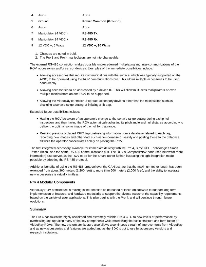
4 Aux + Aux +
5 Ground Power Common (Ground)
6 Aux - Aux -
7 Manipulator 24 VDC - RS-485 Tx
8 Manipulator 24 VDC + RS-485 Rx
9 12 VDC +, 6 Watts 12 VDC +, 30 Watts
Changes are noted in bold.1.The Pro 3 and Pro 4 manipulators are not interchangeable.2.
The external RS-485 connection makes possible unprecedented multiplexing and inter-communications of theROV, accessories and/or sensor devices. Examples of the immediate possibilities include:
Allowing accessories that require communications with the surface, which was typically supported on theAPIC, to be operated using the ROV communications bus. This allows multiple accessories to be usedconcurrently.
Allowing accessories to be addressed by a device ID. This will allow multi-axes manipulators or evenmultiple manipulators on one ROV to be supported.
Allowing the VideoRay controller to operate accessory devices other than the manipulator, such aschanging a sonar's range setting or inflating a lift bag.
Extended future possibilities include:
Having the ROV be aware of an operator's change to the sonar's range setting during a ship hullinspection, and then having the ROV automatically adjusting its pitch angle and hull distance accordingly todeliver the optimal sonar image of the hull for that range.
Reading previously placed RFID tags, retrieving information from a database related to each tag,recording new images and other data such as temperature or salinity and posting these to the database,all while the operator concentrates solely on piloting the ROV.
The first integrated accessory, available for immediate delivery with the Pro 4, is the KCF Technologies SmartTether, which uses the same RS-485 communications bus. The ROV's Compass/NAV node (see below for moreinformation) also serves as the ROV node for the Smart Tether further illustrating the tight integration madepossible by adopting the RS-485 protocol.
Additional benefits of using the RS-485 protocol over the CAN bus are that the maximum tether length has beenextended from about 360 meters (1,200 feet) to more than 600 meters (2,000 feet), and the ability to integratenew accessories is virtually limitless.
Pro 4 Modular Components
VideoRay ROV architecture is moving in the direction of increased reliance on software to support long termimplementation of features, and hardware modularity to support the diverse nature of the capability requirementsbased on the variety of user applications. This plan begins with the Pro 4, and will continue through futureevolutions.
Summary
The Pro 4 has taken the highly acclaimed and extremely reliable Pro 3 GTO to new levels of performance byoverhauling and updating many of the key components while maintaining the basic structure and form factor ofVideoRay ROVs. The new system architecture also allows a continuous stream of improvements from VideoRayand as new accessories and features are added and as the SDK is put to use by accessory vendors andresearch institutions.
264

Pro 4 Features and Capabilities Updates
The Pro 4 has been extensively updated to include many enhanced features and extended capabilities.
Pro 4 User Interface
The Pro 4 includes a custom hand controller that is built using the same industrial controls found in the Pro 3controller. This controller is delivered with a default configuration, but can be customized to accommodate anyuser's preferences. Additionally, any COTS or custom controller that works with a PC can be used with the Pro 4,including wearable and immersive devices such as gloves and head mounted display/controllers.
Video can be displayed on two monitors, the built-in monitor and the PC display. Alternately, the video can bedisplayed on one screen while the other displays an accessory output such as a sonar or position tracking chart.
The Pro 4 video can be recorded digitally (on the included PC), or using standard analog devices (usersupplied), or both. Digital recording of still images and/or video is built into the control panel and can be executedwith the push of a button on the controller. Digital recording is in industry standard formats and ready fornon-linear editing, on-line sharing, or DVD authoring.
The included PC can be configured to run accessory applications such as sonars, position tracking systems,VideoRay's radiation detector and other sensors.
Sensor feedback is provided onscreen and includes the camera tilt and focus positions, lights setting, andinformation from other onboard sensors, including temperature, humidity, power and communications status.
Pro 4 Power and Thruster Technology
The Pro 4 power supply has been upgraded from 48 Volts DC to 75 V DC, but still maintains the same lowpower consumption of the Pro 3 due to more efficient power circuitry. To support this increase safely, the Pro 4incorporates a Line Insulation Monitor (LIM) protection circuit. Like a GFCI, the LIM detects minor changes thatindicate a fault and safely powers down the system if a fault is detected.
The voltage specifications at the accessory port have changed. The main bus is now 24 Volts DC, but it isisolated from the tether ROV power circuit and better regulated so that it is less susceptible to voltage variationsunder thruster load. The 12 Volt DC available on the accessory port is now capable of supporting loads up to 30Watts instead of the 6 Watts available in the Pro 3.
The VideoRay Pro 4's now includes custom designed and highly efficient brushless thrusters that deliverunparalleled performance and reliability. In order to provide the optimal blend of power and control, the VideoRayPro 4's thrusters incorporate the following features:
The horizontal thrusters, coupled with hydrodynamically optimized propellers and nozzles, produce thehighest thrust-to-vehicle weight and thrust-to-drag ratios in the industry. This combination ensures userswill have the power when they need it, along with the ability to pull long umbilicals and work in currents thatdivers wouldn't dare attempt.
Direct drive horizontal thrusters improve efficiency and reliability over the Pro 3 GTO.
The thruster placement and counter rotation provide a zero turning radius and extremely agilemaneuverability as well as a stable platform for the camera and sensors.
Vertical thrust now incorporates a 65 mm three bladed propeller, and ducted channels under the floatblock. The enhanced vertical thrust and pitch-controlled dive and surface modes expand on the raw powerof the new thruster motor and propeller to deliver significantly higher performance than the Pro 3.
Motor controllers are tuned for lightning-fast responsiveness. In conjunction with joystick sensitivity andindependently adjustable gain these features ensure precision handling and the dexterity to maneuver ormaintain position as needed.
265

Pro 4 Camera
The VideoRay Pro 4 is equipped with 2 high resolution color cameras.
The main camera is located in the forward pressure hull and the second camera can be positioned on top of orunderneath the ROV. The forward camera tilts 180 degrees while the second camera tilts 180 degrees and pans360 degrees providing full hemispherical coverage.
Both cameras are equipped with wide dynamic range and backlight compensation to deliver the highest qualityimages even in difficult lighting situations. The cameras are optimized for underwater use and offer ultra low-lightsensitivity (0.0001 lux).
There are more than 20 user controllable settings that can be managed from the surface including automatic ormanual switching between color and black and white modes, an automatic shutter and digital zoom capabilities.
Camera tilt and focus are now controlled using servo motors, which allow faster operation, precise positioningand feedback as to their current position. Position information for tilt and focus is displayed in the user interface.
Pro 4 Lights
The new highly efficient and high intensity LED lighting provides 3,600 lumens at a color temperature of 6500K.This intensity and color temperature provides significantly improved penetration at depth. The intensity can beboosted to 5,700 lumens and LEDs with different color temperatures will be available in the future.
The forward light reflectors have been engineered to distribute the light evenly throughout the camera tilt range,such that at 45 degrees vertically, the Pro 4 projects more light than other ROVs do straight ahead at the samedistance.
Like the Pro 3, the lights are positioned outside the main hull to provide the greatest separation from the cameraand to make servicing easier (although the service rating of the LED lights makes servicing virtually unnecessary).This separation is extremely important in minimizing backscatter due to suspended particles in the path from thelights to the camera target, and results in higher quality images.
The setting of the intensity of the lights is displayed in the user interface.
Pro 4 Compass and Navigation
The Pro 4's navigation system includes a 3 axis compass, accelerometer, and MEMS Rate GYRO. Thesedevices are mounted on a single board and are the same as one of the nodes in the KCF Technologies SmartTether.
You do not need to calibrate the compass.
The heading of the ROV is displayed in the compass and its attitude (pitch and roll) in the attitude indicator.
Pro 4 Depth Gauge
The Pro 4's depth gauge is much more sensitive and has about 10 times the resolution of the Pro 3's depthgauge. You do not need to calibrate the depth gauge.
Auto-Pilot Modes
Auto heading is now included in addition to auto depth, and both features now support the traditional "set andforget" mode and a new "go to" mode.
Pro 4 Additional Sensors
Temperature and humidity sensors have been added to the internal components of the Pro 4 ROV.
Pro 4 Float Block
The Pro 4 float block has been redesigned to be more hydrodynamic, more durable and provide variablefloatation to match the accessory payload.
266

Pro 4 Skid and Ballast System
The Pro 4 skid and ballast system have been redesigned to be stronger, more hydrodynamic and allow theballast to be adjusted without requiring any tools. The system consists of a central accessory mounting adapterplate and two ballast weight pods. The weight pods are hinged and hold the ballast weights in slots that allow thepitch trim to be fine tuned.
Pro 4 Depth Rating
The Pro 4 depth rating has been increased to 305 meters (1000 feet) by using a stiffer hull, but the overall weightof the Pro 4 has been reduced when compared to the Pro 3 GTO.
267

Compatibility Issues between the Pro 3 and Pro 4
There are several compatibility issues between the Pro 4 and prior versions.
Control Panel
The control panel has been changed significantly from the Pro 3 to the Pro 4. The Pro 4 uses 74 Volts DC in thetether, while the Pro 3 uses 48 Volts DC.
Do not attempt to plug a Pro 3 ROV into a Pro 4 control panel, or a Pro 4 ROV into a Pro 3 controlpanel. Doing so may cause damage to the components.
Accessory Port
The accessory port has been changed from the Pro 3 to the Pro 4. The table below lists the changes.
Pin Function (Pro 3 / Deep Blue) Function (Pro 4)
1 Video - Video -
2 Video + Video +
3 48 VDC + (30 Watts) 24 VDC + (30 Watts*)
4 Aux + Aux +
5 Ground Power Common (Ground)
6 Aux - Aux -
7 Manipulator 24 VDC - RS-485 -/A
8 Manipulator 24 VDC + RS-485 +/B
9 12 VDC + (6 Watts) 12 VDC + (30 Watts*)
Lights
The Pro 3 and Pro 4 lights are not interchangeable between these two systems even though theconnectors are the same. Using a Pro 3 light bulb on a Pro 4 ROV, or a Pro 4 LED on a Pro 3 ROV may causedamage to the lights or the ROV.
Manipulator
The Pro 3 and Pro 4 manipulators are not interchangeable between these two systems eventhough the connectors are the same. Using a Pro 3 manipulator on a Pro 4 ROV, or a Pro 4 manipulator on a Pro3 ROV may cause damage to the manipulator or the ROV. You can tell the difference between Pro 3 and Pro 4manipulators by the length of the main body. The Pro 3 body is about 75 mm (3 inches), while the Pro 4 body isabout two times as long at 150 mm (6 inches). The Pro 3 manipulator uses pins 7 and 8 for + or - 24 Volts DC todrive the motor. The Pro 4 manipulator includes a processor board to allow multiple manipulators to be used onone ROV. On the Pro 4 manipulator, pins 7 and 8 are used for communications, pins 3 and 5 are used for power(24 Volts DC) and pin 12 is used to power the processor board (12 Volts DC, converted to 5 Volts DC on theboard).
Calibration
The Pro 4's depth gauge and compass do not need to be calibrated.
268

Run Time
The run time of the Pro 3 is stored in the control panel. The run time of the Pro 4 is stored in the ROV. Thisprovides a more accurate representation of the amount of hours of use of the ROV.
Tether
VideoRay tether can be used with any model. The maximum tether length of the Pro 4 has been increased fromabout 365 meters (1,200 feet) for the Pro 3 to about 600 meters (2,000 feet).
269